WO2011129017A1 - 靴のアッパーの前足部の構造 - Google Patents
靴のアッパーの前足部の構造 Download PDFInfo
- Publication number
- WO2011129017A1 WO2011129017A1 PCT/JP2010/056875 JP2010056875W WO2011129017A1 WO 2011129017 A1 WO2011129017 A1 WO 2011129017A1 JP 2010056875 W JP2010056875 W JP 2010056875W WO 2011129017 A1 WO2011129017 A1 WO 2011129017A1
- Authority
- WO
- WIPO (PCT)
- Prior art keywords
- flexible
- main
- foot
- oblique
- edge
- Prior art date
Links
Images


Classifications
-
- A—HUMAN NECESSITIES
- A43—FOOTWEAR
- A43B—CHARACTERISTIC FEATURES OF FOOTWEAR; PARTS OF FOOTWEAR
- A43B23/00—Uppers; Boot legs; Stiffeners; Other single parts of footwear
- A43B23/02—Uppers; Boot legs
- A43B23/0245—Uppers; Boot legs characterised by the constructive form
- A43B23/0265—Uppers; Boot legs characterised by the constructive form having different properties in different directions
- A43B23/027—Uppers; Boot legs characterised by the constructive form having different properties in different directions with a part of the upper particularly flexible, e.g. permitting articulation or torsion
-
- A—HUMAN NECESSITIES
- A43—FOOTWEAR
- A43B—CHARACTERISTIC FEATURES OF FOOTWEAR; PARTS OF FOOTWEAR
- A43B23/00—Uppers; Boot legs; Stiffeners; Other single parts of footwear
- A43B23/02—Uppers; Boot legs
- A43B23/0205—Uppers; Boot legs characterised by the material
- A43B23/0235—Different layers of different material
-
- A—HUMAN NECESSITIES
- A43—FOOTWEAR
- A43B—CHARACTERISTIC FEATURES OF FOOTWEAR; PARTS OF FOOTWEAR
- A43B23/00—Uppers; Boot legs; Stiffeners; Other single parts of footwear
- A43B23/02—Uppers; Boot legs
- A43B23/0245—Uppers; Boot legs characterised by the constructive form
-
- A—HUMAN NECESSITIES
- A43—FOOTWEAR
- A43B—CHARACTERISTIC FEATURES OF FOOTWEAR; PARTS OF FOOTWEAR
- A43B23/00—Uppers; Boot legs; Stiffeners; Other single parts of footwear
- A43B23/02—Uppers; Boot legs
- A43B23/0245—Uppers; Boot legs characterised by the constructive form
- A43B23/0255—Uppers; Boot legs characterised by the constructive form assembled by gluing or thermo bonding
-
- A—HUMAN NECESSITIES
- A43—FOOTWEAR
- A43B—CHARACTERISTIC FEATURES OF FOOTWEAR; PARTS OF FOOTWEAR
- A43B23/00—Uppers; Boot legs; Stiffeners; Other single parts of footwear
- A43B23/02—Uppers; Boot legs
- A43B23/0245—Uppers; Boot legs characterised by the constructive form
- A43B23/0265—Uppers; Boot legs characterised by the constructive form having different properties in different directions
- A43B23/0275—Uppers; Boot legs characterised by the constructive form having different properties in different directions with a part of the upper particularly rigid, e.g. resisting articulation or torsion
-
- A—HUMAN NECESSITIES
- A43—FOOTWEAR
- A43B—CHARACTERISTIC FEATURES OF FOOTWEAR; PARTS OF FOOTWEAR
- A43B23/00—Uppers; Boot legs; Stiffeners; Other single parts of footwear
- A43B23/08—Heel stiffeners; Toe stiffeners
- A43B23/081—Toe stiffeners
Definitions
- the present invention relates to an improved structure of a forefoot portion of a shoe upper.
- the material of the upper shell is required to be non-stretchable and high in strength.
- the upper is often reinforced with artificial leather, synthetic leather or a belt.
- Such a crust is highly rigid. Therefore, it becomes difficult for the upper shell to fit on the foot. For example, when raising the buttocks that frequently appear in the above-mentioned court competitions, when raising the heels and twisting them inside, or when raising the heels and twisting them outside, large heels are formed on the upper forefoot, Is easily pressed locally.
- Patent Document 1 discloses a toe reinforcing member in which a notch portion is formed at a portion corresponding to a bent portion of a front stepping portion of a shoe.
- Patent Document 2 discloses an upper that is easy to bend and is not easily deformed even when a force is applied in the lateral direction by means of comb-like reinforcing sheets facing each other inside and outside.
- Patent Document 3 discloses an upper in which a substantially cross-shaped notch is formed in the upper toe and an elastic member is sewn in the notch.
- an object of the present invention is to provide an improved structure of the front foot portion of the upper that can obtain both the holding state of the front foot and along the foot (followability) with less feeling of pressure when flexing.
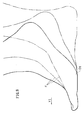
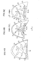
- FIG. 7 shows an example of the upper.
- the present invention is a structure of a forefoot portion of an upper U of a shoe having soles 51, 52 for supporting a sole and an upper U covering an instep, wherein the forefoot portion of the upper U has a low rigidity region AL and a high Includes a rigid region AH, and the low-rigid region AL covers a part of the toe of the foot and is easier to extend and bend than the high-rigid region AH.
- main portion comprising a portion of the site to the longitudinal direction Y and the longitudinal first base section spread in the transverse direction X perpendicular to the direction the bone B3 clause 1 of the bone bodies second group bone B3 2 of the bone of the foot in the middle 10, toward the inside of the foot from the main portion 10 in the transverse direction X or obliquely rearward covers part of the site from the first base phalanx B3 1 of the bone body to the first in the bone head metatarsal B4 1 a first flexible part 11 among continuing to the main portion 10 extending Te, section 3 group bone B3 3 or the
- the outer first flexible portion 21 that covers a part from the bone body to the bone bottom of the four proximal phalanges B3 4 extends in the transverse direction X or obliquely rearward from the main portion 10 toward the outside of the foot and continues to the main portion 10.
- the inner first flexible portion 11 and the outer first flexible portion 21 are formed on a straight line that crosses the main portion 10 in the transverse direction X, or protrudes forward across the main portion 10 and forward.
- the high-rigidity area AH covers the other part of the toe around the main portion 10, is less likely to extend than the low-rigidity area AL, and is not easily bent.
- the high-rigidity area AH is The peripheral edge 30 that covers the periphery of the toe at each of the inner side, the outer side, and the distal end of the foot, and the rear edge of the inner first flexible part 11 that is connected to the peripheral edge 30 and the first middle an inner rear reinforced portion 31 covering a part of the metatarsal B4 1 condyle, extending from the peripheral portion 30 continuous with the peripheral edge 30 in contact the leading edge of said first flexible part 11 toward the main portion 10 the a front reinforcing portion 32 inner cover part of the first base phalanx B3 1 of bone bodies, the outer rear reinforced portion 41 continuous to the peripheral edge 30 in contact with the trailing edge of said outer first flexible portion 21, the outer second An outer front reinforcing portion 42 that is in contact with the front edge of the flexible portion 21 and continues to the peripheral portion 30 and extends from the peripheral portion 30 toward the main portion 10; and the oblique portion provided at the front and rear edges of the oblique portion And a portion in contact with the front edge and
- FIG. 8 is a side view showing a change in the shape of the foot F stepping forward Y1.
- the sole when stepping forward, the sole is greatly bent at a middle foot-to-phalangeal joint (hereinafter referred to as an MP joint).
- the soles of the first to third metatarsals including the base ball O1 behind the MP joint and the front toes are grounded on the sole.
- the upper surface of the toe of the foot is bent in the vicinity of the MP joint in the front Y1 with respect to the main ball O1.
- the bending position of the upper surface of the front foot of the foot is different from the bending position of the sole.
- it is inevitable that a deviation occurs between the bent state of the upper surface of the foot and the bent state of the upper Therefore, the relationship between the upper during foot flexion and the upper surface of the forefoot of the foot was examined by the following method.
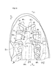
- FIG. 9A is a plan view showing measurement points S1 to S9 at which the contact pressure generated between the foot and the upper is measured
- FIG. 9B is a graph showing pressures measured at the measurement points S1 to S9. The pressure was measured in a state where a commercially available tennis shoe was worn and the heel was raised 130 mm.
- the first group phalange of bone B3 1 wherein the pressure is greater at the site of the third base phalanx B3 3 of the bone bodies and second metatarsal B4 2 condyle. Therefore, if the pressure at these parts is reduced, it is presumed that along the foot (followability) with less feeling of pressure during bending can be obtained.
- the low-rigidity area AL that is easier to extend and bend than the high-rigidity area AH includes the main portion 10, the inner first flexible portion 11 and the outer first flexible portion that extend inward and outward from the main portion 10. 21.
- the main portion 10 covers a portion of the first base phalanx B3 1 of the bone body to second base phalange of bone B3 2, wherein the first flexible portion 11 bones of the first base phalanx B3 1 It covers part of the site from the body to the first in the bone head metatarsal B4 1, wherein the outer first flexible portion 21 extends outwardly of the foot from the main portion 10. Therefore, the inner first flexible portion 11 and the inner second flexible portion 12 are provided on the first bending line L1 where the upper surface of the toe bends or just before the line L1.
- the upper part of the upper tightened with shoelaces fits the instep, and the tip of the toe is fixed to the sole stepped on with the toes. Therefore, it is desirable that the upper bends between the tip of the toe and the upper part.
- the flexible belt-like region extending in the lateral direction from the inner first flexible portion 11 to the outer first flexible portion is disposed in front of the main ball O1 of FIG. Therefore, as the foot is bent, the upper is bent in the flexible band-like region, and the pressure from the upper to the foot is small.
- the inner first flexible portion 11 and the outer first flexible portion 21 of FIG. 7 are arranged along a straight line that crosses the main portion 10 in the transverse direction X or a curve that curves convexly forward. Therefore, the 1st flexible part 11 or the 1st flexible part 21 is arrange
- the periphery of the toe is covered with a highly rigid peripheral portion 30, and the front and rear portions of the flexible portions are covered with the reinforcing portions. Therefore, the function of holding the toes with the upper during violent movements in front, back, left, and right in court-based competitions is unlikely to be impaired.
- the high rigidity region is more difficult to stretch than the low rigidity region, and the Young's modulus of the member forming the high rigidity region is larger than that of the low rigidity region, so that the high rigidity region is higher than the low rigidity region.
- the Young's modulus of the member forming the high rigidity region is larger than that of the low rigidity region, so that the high rigidity region is higher than the low rigidity region.
- the sheet-like member is difficult to stretch. Due to the high rigidity of the member in the high rigidity region, the foot is supported by the upper inside and outside, and the holding of the foot is stabilized.
- the low rigidity region is more easily bent than the high rigidity region.
- the Young's modulus of the sheet-like member forming the low rigidity region is smaller than that of the high-rigidity region, and thus occurs in the sheet-like member.
- the bone bottom refers to a portion that is slightly thicker and bulges near the rear joint in each bone, and is also called the proximal head.
- the bone head is slightly thicker near the front joint in each bone. This refers to the swollen area, also called the distal bone head.
- the bone body means a portion between the bone bottom and the bone head, and the thickness generally changes smoothly.
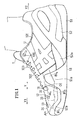
- FIG. 1 is an inner side view of a shoe according to a first embodiment of the present invention as viewed from the inside.
- FIG. 2 is an outer side view of the shoe viewed from the outside.
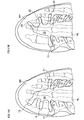
- 3A is a plan view of the front foot portion of the shoe as seen from above, and
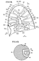
- FIG. 3B is a partially enlarged view of the upper of the shoe.
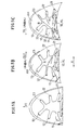
- FIG. 4A, FIG. 4B, and FIG. 4C are plan views showing the deformation of the upper forefoot portion before and after the bending of the foot, respectively.
- 5A, 5B and 5C are plan views showing deformation of the forefoot part before bending, external torsion and internal torsion of the foot, respectively.
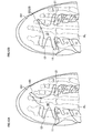
- FIG. 6A is a plan view of the forefoot part for showing the material of the sole and the upper
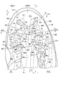
- FIG. 7 is a plan view of the forefoot portion showing the relationship between the low-rigidity region, the high-rigidity region, and the foot skeleton.
- FIG. 8 is an inner side view of the foot showing the state of bending of the foot as viewed from the inside.
- FIG. 9A is a plan view of a foot skeleton showing measurement points
- FIG. 9B is a graph showing contact pressure at each measurement point.
- FIG. 10A is a plan view showing a flexible portion and an oblique portion according to a shoe of Example 2 of the present invention
- FIG. 10B is a plan view of the shoe according to Example 3 of the present invention.
- FIG. 10A is a plan view showing a flexible portion and an oblique portion according to a shoe of Example 2 of the present invention
- FIG. 10B is a plan view of the shoe according to Example 3 of the present invention.
- FIG. 11A is a plan view showing a flexible portion and an oblique portion according to a shoe of Example 4 of the present invention
- FIG. 11B is a plan view of the shoe according to Example 5 of the present invention
- 12A is a plan view showing a flexible portion and an oblique portion according to a shoe of Example 6 of the present invention
- FIG. 12B is a plan view of the shoe according to Example 7 of the present invention
- FIG. 13A is a plan view showing a flexible portion and an oblique portion according to a shoe of Example 8 of the present invention
- FIG. 13B is a plan view of the shoe according to Example 9 of the present invention.
- FIG. 14A is a plan view showing a forefoot portion of a shoe of Example 10 of the present invention
- FIG. 14B is a cross-sectional view of the shoe along the XIVB-XIVB ridge line.
- FIG. 15 is a plan view of the forefoot portion showing the relationship between the low rigidity region, the high rigidity region, and the foot skeleton of Example 10.
- FIG. 16A, FIG. 16B, and FIG. 16C are plan views showing deformation of the forefoot part before bending, external twisting, and internal twisting of the foot, respectively.
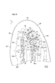
- FIG. 17 is a plan view of the forefoot portion showing the upper of Example 11 and showing the relationship between the low rigidity region, the high rigidity region and the foot skeleton.
- FIG. 18 is a plan view of the forefoot part showing the upper of Example 12 and showing the relationship between the low rigidity region, the high rigidity region and the foot skeleton.
- the inner first flexible portion 11 extends to the inner side of the ridge line L10 of the main collar, the oblique portion is in contact with the front edge of the inner front reinforcing portion 32, and the first collar extending from the main portion 10 in the rear section joints J 1 to the inside than the edge line L10 of the hallux obliquely forward of the inside of the leg.
- the bending on the side of the main heel is larger than the bending on the side of the small heel, so that the bending on the side of the upper heel is also large.
- the legs tend to bend along the third and fourth MP joints MP 3 and MP 4 .
- the flexible oblique portion 12 is provided behind the first intercostal joint J 1 and on the front edge of the inner second reinforcing portion (inner front reinforcing portion) 32.
- the upper is easily bent in the vicinity of the second bending line L2. Therefore, it is easy for the upper to follow the foot during the “external twist”.
- second reinforcing portion inner (inner front reinforcing portion) 32 covers the third base section outer surface of the bone B3 1, stability for holding the hallux is hardly impaired.
- the inner first flexible portion 11 extends to the inner side of the ridge line L10 of the main shaft, and the oblique portion is forward of the outer first flexible portion 21 and the main portion. 10 toward the outer front of the foot diagonally forward of the second heel bone B1 2 or the third heel end phalanx B1 3 , or the second heel and third heel unphalange B1 2 , B1 3 It extends to the part between.
- the foot bends at the third bend line L3 in addition to the first bend line L1 of FIG. 9A.
- the inclined portion 23 extends to the distal phalanges B1 2 and B1 3 of the second heel or the third heel, so that the third bending line having a large inclination is provided.
- the upper is easy to bend in the vicinity of L3. Therefore, it is easy for the upper to follow the foot during the “inner twist”.
- the oblique portions are respectively provided on the inner and outer sides, the inner oblique portions are in contact with the front edge of the inner front reinforcing portion 32, and the first intercostal joint J 1 extends from the main portion 10 toward the diagonally forward side of the foot toward the inner side of the ridge line L10 of the main shaft, and the outer diagonal portion is positioned forward of the outer first flexible portion 21 in the forward direction.
- the second phalanx B1 2 or the third phalanx phalange B1 3 , or the second and third heel unphalanges B1 2 , B1 from the main part 10 diagonally forward of the outside of the foot.
- an angle ⁇ 23 formed by a virtual line along the extending direction of the outer diagonal portion and a virtual horizontal line along the transverse direction X is an angle of the inner diagonal portion. It is larger than an angle ⁇ 12 formed by a virtual line along the extending direction and the horizontal line. .
- a plurality of the at least one oblique portion are provided on the outside, and one of the oblique portions is in contact with a front edge of the outer front reinforcing portion 42, and An outer second flexible portion 22 extending from the main portion 10 toward the diagonally forward side of the outer side of the foot is configured, and another one of the plurality of diagonal portions is located in front of the outer second flexible portion 22 in the forward direction.
- the second phalanx B1 2 or the third phalanx phalange B1 3 or the second and third heel unphalanges B1 2 , B1 from the main part 10 diagonally forward of the outside of the foot.
- outer third flexible portion 23 constitutes an outer third flexible portion 23 extending to a portion between 3 , and the outer second flexible portion 22 and the outer third flexible portion 23 are spaced apart from each other across a portion of the high-rigidity region AH.
- a virtual line along the extending direction of the outer third flexible portion 23 and a virtual line along the transverse direction X The angle ⁇ 23 formed by the horizontal line is larger than the angle ⁇ 22 formed by the virtual line along the extending direction of the outer second flexible portion 22 and the horizontal line.
- the upper When the foot is largely bent in the “inner twist” phase, the upper is largely bent at the bending line L3 in FIG. 9A. At this time, if there is only one oblique portion on the outer side, the large bending of the upper may be insufficiently absorbed only by the inner first flexible portion 11 and one oblique portion 23. On the other hand, since the two flexible portions 22 and 23 that are the oblique portions are bent on the outside, the upper can easily follow the foot even in a situation where the “inner twist” is large.
- the at least one oblique part includes an oblique part provided on the inner side, the inner oblique part is in contact with the front edge of the inner front reinforcing part 32, and toward from the main portion 10 behind the joint J 1 between 1 metatarsophalangeal obliquely forward of the inside of the leg constitutes a second flexible part 12 among which extends to the inside than the edge line L10 in the hallux, the outer third flexible part
- the angle ⁇ 23 formed by an imaginary line along the extending direction of 23 and an imaginary horizontal line along the transverse direction X is equal to the imaginary line along the extending direction of the inner second flexible portion 12 and the lateral line. It is larger than the angle ⁇ 12 formed by the line.
- the inside of the foot is also bent greatly. Therefore, as in this embodiment, the upper two flexible portions bend in addition to the three outer flexible portions, so that the upper can easily follow the foot even in the large “inner twist” phase.
- the provision of the three flexible parts on the outside and the two flexible parts on the inside not only improves the upper leg along the large “inner twist” and “external twist”, but also increases the leg toward the front. The upper leg along when it is bent greatly improves.
- a plurality of the at least one oblique portions are provided on the inner side, and one of the oblique portions is in contact with a front edge of the inner front reinforcing portion 32.
- an inner second flexible portion 12 that extends from the main portion 10 to the inside of the foot toward the inside of the ridge line L10 of the main heel behind the first intercostal joint J 1 .
- Another one of the oblique portions constitutes an inner third flexible portion 13 that extends forward from the main portion 10 toward an oblique front inside the foot in front of the inner second flexible portion 12.
- the upper When the foot is greatly bent in the “external twist” phase, the upper is greatly bent along the bending line L2 (FIG. 9A), and a large load is applied to the third and fourth heels. The upper also tends to bend at the tip of the arm. On the other hand, since the two flexible portions 12 and 13 that are the oblique portions are bent, the upper can easily follow the legs even in a situation where the “external twist” is large.
- the main portion 10 extends toward the front or obliquely forward from the second metatarsal B4 2 condyle to said second base phalanx B3 2 of the bone bodies.
- the upper includes a tongue covering the instep, the main portion 10 is connected to the tongue, and the main portion 10 moves forward as the transverse direction X is reached.
- the width of is small.
- the head of the second metatarsal bone is easily covered with the low rigidity region AL. Further, when the width of the main portion 10 decreases as it approaches the tip of the upper, it is easy to ensure a foot holding function by the peripheral edge portion 30 of the upper.
- the peripheral edge portion 30 of the high-rigidity region AH covers the inner side surface of the main body further on the inner side of the inner first flexible portion 11, and further on the outer first flexible portion 21. Cover the outside surface of the gavel on the outside.
- the outer first flexible portion 21 extends to the outside than the outer edge of the third base phalanx B3 3 from the main portion 10. In this case, the upper is easily bent in the bending line L1.
- the length of the inner and outer first flexible portions 11 and 21 in the transverse direction X is greater than the width of the inner and outer first flexible portions 11 and 21 in the front-rear direction Y. Is big.
- each flexible part has a long length along the first bending line L1 (FIG. 9A).
- the low-rigidity area AL is formed by a sheet-like first member that forms the upper, and the high-rigidity area AH is the first member and the first member.
- a second member which is laminated on the surface of the first member and is less likely to extend than the first member.
- the first member for example, mesh fabric, knitted fabric, woven fabric, non-woven fabric, synthetic leather, natural leather, or the like can be used as appropriate.
- the second member for example, resin, rubber, fiber material, or the like can be appropriately used by bonding, bonding, sewing, or applying to the first member.
- first member and the second member may be laminated by being bonded or glued to each other, but may be joined by partially overlapping, bonding, sewing, or the like without being laminated.
- material of each part of the upper can be appropriately used as long as it does not substantially hinder the action and effect of the present invention.
- the second member includes an inner edge portion 301 that covers the inner surface of the main cage, an outer edge portion 302 that covers the outer surface of the gavel, and the inner edge portion 301 or the outer edge portion.
- a plurality of convex portions protruding from 302 toward the main portion 10 and spaced apart from each other in the front-rear direction Y are defined, and a concave portion forming the oblique portion is defined between the plurality of convex portions.
- the second member has a bank-shaped ridge extending from the inner and outer side edge portions 301 and 302 to the convex portion, and the ridge portion 65 is formed on the edge of the convex portion. More preferably, it extends along.
- the protrusions have high tensile rigidity and bending rigidity when the upper is bent due to the protrusions.
- the first member is formed of a net-like member having air permeability
- the second member is formed of a synthetic resin having a plurality of through holes that allow air to pass. Air permeability is ensured also in the high-rigidity area AH, and the upper is likely to bend appropriately in the high-rigidity area AH.
- each of the flexible portions 11 and 21 and the oblique portion has a width in a width direction orthogonal to a direction in which the flexible portion and the oblique portion extend, and each of the widths is the main portion. It gets bigger as it gets closer to 10.
- the width of the reinforced portion can be secured wide in the vicinity of the peripheral edge portion 30, and a long flexible portion and a slant portion are easily formed along the bending line.
- each of the convex portions has a width in the width direction orthogonal to the direction in which the convex portions extend, and the width of the convex portions decreases as the main portion 10 is approached.
- the concave portion has a width in the width direction perpendicular to the direction in which the concave portion extends, and the width of the concave portion increases as the main portion 10 is approached.
- the inner and outer concave portions and the concave portions are easily connected smoothly by virtual lines via the main portion 10, and therefore, the upper is easily bent along the respective bending lines.
- the rear edges of the inner and outer first flexible portions 11 and 21 extend obliquely rearward.
- the inner and outer first flexible portions 11, 12 extending obliquely rearward will be smoothly connected to the oblique portion extending obliquely forward via the main portion 10.
- the inner first flexible portion 11 extends to the inner side of the ridge line L10 of the main shaft. In this case, in the inner first flexible portion 11, the upper is easily bent.
- Example 1 1 to 7 show a shoe (for right foot) of Example 1.
- the shoe of this embodiment includes soles 51 and 52 that absorb the impact of landing, and an upper U that wraps the instep.
- the sole supports the sole and includes an outsole 51 and a midsole 52.
- the upper U is provided with a plurality of insertion holes 100 such as eyelet holes. By tightening the shoe race 103 (an example of a tightening member) inserted through these insertion holes 100, the upper U fits the instep.
- the upper U has a first opening 101 from which a leg rises when worn, and a second opening 102 located in front Y1 of the first opening 101 and closed by a tongue piece T. ing.
- the first and second openings 101 and 102 are connected to each other in the front-rear direction Y.
- the tongue T covers the instep.
- FIG. 6A shows the material of the upper and the sole.
- a winding upper portion 51a shown by hatching is formed by largely winding a rubber outsole 51 (FIG. 1), and supports the inside of the foot.
- a winding upper part 52a shown by hatching different from the hatching is formed by winding up a midsole 52 (FIG. 1) made of foamed resin and supports the periphery of the foot.
- the forefoot portion of the upper includes a low-rigidity area AL and first and second high-rigidity areas AH 1 and AH 2 .
- the low rigidity area AL is not subjected to halftone dots or hatching.
- the high rigidity region AHi H i are subjected to dot or hatch, Among the high rigidity region AH i, dot density is high and more the second high-rigidity region AH 2 high rigidity facilities Has been.
- the low rigidity region AL is easily extended than the high rigidity region AH i covers a portion of the toe of the foot, and is easy to bend.
- the high-rigidity region AH i covers the other part of the toe around the low-rigidity region AL, the less likely elongation than low rigidity region AL, and less likely to be bent. Therefore, when the foot is bent and the upper is bent, wrinkles are generated in the upper in the low rigidity region AL, and the material of the upper is loosened. Incidentally, small wrinkles curvature than wrinkles in the high rigidity region AH 1 occurs in the low rigidity region AL.
- the low-rigidity area AL is formed by a flexible sheet-like first member 61 that forms the upper U.
- the first high-rigidity region AH 1 in FIG. 6A is formed by the first member 61 and a second member 62 that is stacked on the surface of the first member 61 in FIG. 6B and is less likely to extend than the first member 61. Yes.
- the second high rigidity region AH 2 is formed by welding or sewing a non-stretchable third member 63 on the first and second members 61 and 62 forming the first high rigidity region AH 1. Is formed.
- FIG. 6B and FIG. 14B which will be described later, the first to third members 61 to 63 are shown as diagrams for easy understanding of the drawing.
- the first member 61 is formed of a net-like member having air permeability
- the second member 62 is formed of a synthetic resin having a plurality of through holes 64 that allow air to pass.
- the synthetic resin second member 62 may be formed integrally with the first member 61.
- the third member 63 synthetic leather, resin, tape material, or the like that generally forms eyelets (constructs eyelet decoration) can be used.
- rubber the wrapping section 51a covers a part of the surface of the third member 63, constitutes a part of the high rigidity region AH 2, most high rigidity.
- the low rigidity region AL includes a main portion 10, a plurality of inner first flexible portions 11 to third flexible portions 13, and outer first flexible portions 21 to third flexible portions 23.
- the main portion 10 is the forefoot of the inside and outside of the foot in the middle longitudinal direction Y and the longitudinal first base section spread in the transverse direction X perpendicular to direction Y of the bone B3 1 from the bone material of the second base phalanx B3 2 Includes part of the area up to the bone.
- the main portion 10 preferably includes a nucleus region 10c described below. It is desirable that the upper be flexible at the three bending lines L1 to L3 and the measurement point S2 where the contact pressure is high in FIG. 9A. Therefore, with the core region 10c is a straight line connecting the joint J 1 between the first metatarsophalangeal and the 2MP joint MP 2 (not shown), between the second metatarsophalangeal joint J 2 and a second 1MP joint MP 1 It is preferable to include the intersection P 10 with a straight line (not shown) and the head of the second metatarsal B 4 2 .
- the nuclear region 10c is first base phalanx B3 1 of bone bodies and the second base phalanx B3 2 and the center point P 10 (FIG. 9A) between the bone bodies, the second in the metatarsal B4 2 It preferably includes a bone head.
- the main portion 10 will contribute to the ease of bending of the upper in all aspects of forward bending, “external twist”, and “internal twist”.
- the outer first flexible portion 21 extends from the main portion 10 toward the outer side OUT of the foot along the transverse direction X and continues to the main portion 10.
- the eyelet decoration formed by the third member 63 of FIG. 6A has cutout portions 111 and 121 extending obliquely rearward. These notches 111 and 121 are connected to the second opening 102 to make the third member 63 easily bent.
- the inner first flexible portion 11 and the outer first flexible portion 21 are arranged on an imaginary straight line indicated by a cross-sectional line VIB-VIB in FIG. 6A that crosses the core region 10c of the main portion 10 in the transverse direction X.
- the core region 10c of the main part 10 of 14A is arranged along an imaginary curve indicated by a cross-sectional line XIVB-XIVB that curves in the transverse direction X and curves convexly toward the front Y1. That is, the inner and outer first flexible portions 11 and 12 are arranged at substantially the same position in the front-rear direction Y, and are opposed to each other in the transverse direction X with the core region 10c interposed therebetween.
- the virtual curve may be a curve and a straight line that are smoothly connected.
- the inner second flexible portion 12 and the inner third flexible portion 13 are disposed on the front Y1 with respect to the first flexible portions 11 and 21, and extend from the main portion 10 toward the inner side IN obliquely forward. 10 is formed as an oblique portion.
- the outer second flexible portion 22 and the outer third flexible portion 23 are disposed on the front Y1 with respect to the first flexible portions 11 and 21, and extend from the main portion 10 toward the outer front OUT obliquely forward. 10 is formed as an oblique portion.
- each of the flexible portions 11 to 13 and 21 to 23 is disposed on the front Y1 with respect to the front end of the eyelet member 63 that is the third member. Further, the eyelet member 63 is separated from the inside and outside at the front end and is not connected.
- the first high rigidity area AH 1 AH 2 is in contact with the low rigidity area AL.
- the first high-rigidity region AH 1 includes a peripheral portion 30, a first inner reinforcing portion 31 to a third inner reinforcing portion 33, a tip reinforcing portion 34, and a first outer reinforcing portion 41 to a third outer reinforcing portion that are connected to the peripheral portion 30. 43.
- the peripheral edge portion 30 is connected to the soles 51 and 52, and includes an inner edge portion 301, an outer edge portion 302, and a tip edge portion 303 that cover the periphery of the toe at the inner side, the outer side, and the front end of the forefoot.
- the leading edge 303 is continuous with the inner edge 301 and the outer edge 302.
- the inner first reinforcing portion (inner rear reinforcing portion) 31 contacts the rear edge 11 b of the inner first flexible portion 11 and continues to the inner edge portion 301.
- the inner first reinforcing part 31 covers a part of the bone head of the first metatarsal bone B41.
- the inner second reinforcing portion (inner front reinforcing portion) 32 is in contact with the front edge 11 f of the inner first flexible portion 11 and the rear edge 11 b of the inner second flexible portion 12, is connected to the peripheral edge portion 30, and the inner edge portion 301.
- Said second reinforcing portion 32 covers a portion of the first base phalanx B3 1 of bone bodies.
- the inner third reinforcing portion (an example of a portion in contact with the oblique portion) 33 is in contact with the front edge 12f of the inner second flexible portion 12 and the rear edge 13b of the inner third flexible portion 13, and is continuous with the inner edge portion 301.
- the inner edge portion 301 extends obliquely rearward toward the main portion 10. It said third reinforcing portion 33 covers the upper surface of the joint J 1 between the first metatarsophalangeal.
- the tip reinforcing portion 34 is in contact with the front edge 13 f of the inner third flexible portion 13 and the front edge 23 f of the outer third flexible portion 23, and continues to the tip edge portion 303 of the peripheral edge portion 30.
- the tip reinforcing portion 34 extends rearwardly Y2 toward the main portion 10 from the leading edge 303, first toe of the distal phalanx B1 1 or the second toe of a portion of the non-phalanx B1 2, or those not yet It is preferable to cover a part of the region between the phalanges B1 1 and B1 2 from the upper surface.
- the outer first reinforcing portion (outer rear reinforcing portion) 41 is in contact with the rear edge 21 b of the outer first flexible portion 21 and continues to the outer edge portion 302.
- the outer first reinforcing part 41 covers part or all of the upper surfaces of the bone bottoms of the third and fourth proximal phalanges B3 3 and B3 4 .
- the outer second reinforcing portion (outer front reinforcing portion) 42 is in contact with the front edge 21 f of the outer first flexible portion 21 and the rear edge 22 b of the outer second flexible portion 22 and continues to the outer edge 302.
- the outer second reinforcing portion 42 extends from the outer edge 302 toward the main portion 10 and covers a part or all of the upper surface of the head of the third or fourth proximal phalanx B3 3 , B3 4. preferable.
- the outer third reinforcing portion (an example of a portion in contact with the oblique portion) 43 is in contact with the front edge 22f of the outer second flexible portion 22 and the rear edge 23b of the outer third flexible portion 23 and continues to the outer edge 302. It said third reinforcing portion 43 outside cover a part or the whole of the upper surface of the third Mifushikotsu B1 3 extends obliquely rearward toward the outer edge 302 to the main portion 10.
- the second member 62 in FIG. 6B includes the inner edge portion 301 that covers the inner surface of the main rod in FIG. 7, the outer edge portion 302 that covers the outer surface of the small rod, and the tips of the main rod and the small rod.
- the tip edge portion 303 covering the front surface and a plurality of convex portions are integrally connected.
- the convex portions form the reinforcing portions 31 to 34 and 41 to 43, and project from the inner edge portion 301, the tip edge portion 303, or the outer edge portion 302 toward the main portion 10.
- the second member 62 defines a recess that forms the flexible portions 11 to 13 and 21 to 23 between the plurality of protrusions.
- the second member 62 has a bank-shaped ridge 65 extending from the inner and outer edges 301 and 302 to the convex portion.
- the protruding portion 65 extends along the edge of the convex portion.
- the inner second flexible portion 12 is in contact with the front edge of the inner second reinforcing portion 32, and obliquely forward from the main portion 10 to the inside of the foot at the rear Y2 of the first intercostal joint J 1.
- the inner ridge line L10 extends to the inner side IN.
- the direction in which the outer third flexible portion 23 extends is more greatly inclined with respect to the transverse direction X than the direction in which the inner second flexible portion 12 extends.
- the outer second flexible portion 22 is in contact with the front edge of the outer second reinforcing portion 42 and the rear edge of the outer third reinforcing portion 43, and from the main portion 10 to the outside of the foot behind the tip of the third heel. Extending diagonally forward. Said third flexible portion 23 the outer second flexible part 22 second toe of the distal phalanx B1 2 or third toe of the non-phalanx toward from the main portion 10 at the front obliquely forward of the lateral side of the foot than the outside B1 Extends to 3 or between them.
- the outer second flexible portion 22 and the outer third flexible portion 23 are spaced apart from each other with the outer third reinforcing portion 43 interposed therebetween.
- the direction in which the outer third flexible portion 23 extends is more greatly inclined with respect to the transverse direction X than the direction in which the outer second flexible portion 22 extends.
- FIG. 4A shows the state of the upper U in the standing position.
- wrinkles ruck
- the second flexible portions 11 and 12 contracted back and forth, while the outer first and second flexible portions 21 and 22 similarly contracted back and forth outside the foot.
- the flexible parts 11 to 13 and 21 to 23 are contracted means that wrinkles are generated in the extending direction of the flexible parts, and therefore the rear edge approaches the front edge of each flexible part (for example, the inner This means that the distance from the front edge to the rear edge of one flexible part is reduced by the rear edge 11b of the first flexible part 11 approaching the front edge 11f.
- wrinkles R along the transverse direction X occurred in the main portion 10 between the inner and outer flexible portions. Further, the shrinkage of the inner third flexible portion 13 and the outer third flexible portion 23 at the tip was extremely small.
- FIG. 5A shows a state of the upper U in a standing position similar to FIG. 4A.
- the part 11 contracted slightly forward and backward, and the inner second flexible part 12 and the outer first flexible part 21 contracted greatly forward and backward.
- a wrinkle R connected to the inner second flexible portion 12 and the outer first flexible portion 21 occurred in the main portion 10 between the inner second flexible portion 12 and the outer first flexible portion 21.
- the shrinkage of the inner third flexible portion 13, the outer second flexible portion 22, and the outer third flexible portion 23 was small.
- the bending line L2 of the foot is convexly curved toward the rear Y2, whereas the upper wrinkle R in FIG. 5B is curved linearly or slightly convex toward the front Y1.
- the reason why the bending line is slightly different between the foot and the upper is that the sheet-like upper is unlikely to bend, unlike the foot, and the upper is constrained at the periphery, and the upper deformation is upward from the foot. It seems to be caused by deformation to move away.
- the “inner twist” can be increased as compared with the “outer twist”.
- the “inner twist” may increase during an exercise such as a court game.
- the width in the transverse direction X of the main part 10 in FIG. 7 is 40 mm or less and 10 mm in the region including the second proximal phalanx B3 2.
- the above is preferable, 13 mm or more is further preferable, and 15 mm or more is most preferable.
- the length of the longitudinal axis Y from the second base phalanx B3 2 of the bone base of the main portion 10 is preferably not more than 15mm or more 60 mm, more preferably not less than 20 mm, most preferably at least 25 mm.
- the main portion 10 preferably extends from the head of the second metatarsal B4 2 to the head of the first or second proximal phalanx B3 1 , B3 2 .
- the outer second flexible portion 22 was deformed while the rise of the heel was small or when the “inner twist” was small. Therefore, when the “inner twist” is small and the wrinkle rise is small, as shown in FIG. 12B, in addition to the inner first flexible portion 11 and the outer first flexible portion 21, the inner second flexible portion is used as an oblique portion. It may be preferred to provide both 12 and the outer second flexible portion 22.
- the inner first flexible portion 11 and the outer first flexible portion 21 in FIG. 13A are arranged on the convex bending line L1 forward, and many portions of the bending line L1 are the inner first flexible portion. 11. It is preferable that the main part 10 and the outer first flexible part 21 are included. Similarly, it is preferable that many portions of the bending line L2 are included in the inner second flexible portion 12, the main portion 10, and the outer first flexible portion 21, and many portions of the bending line L3 are included in the inner first flexible portion 11, It would be preferable to be included in the main part 10 and the outer third flexible part 23.
- the recesses forming the inner flexible parts 11 and 12 and the outer flexible parts 21 to 23 are formed such that the width W1 of the recesses increases as the main part 10 is approached, as shown in FIG. 13A. preferable.
- each concave portion tends to include a smooth curve. Therefore, the inner first flexible portion 11 and the outer first flexible portion 21 are easily disposed on the bending line L1, and the inner second flexible portion 12 and the outer first flexible portion 21 are easily disposed on the bending line L2.
- the first flexible part 11 and the outer third flexible part 23 are easily arranged on the bending line L3.
- the width W1 of the recesses is the length in the direction perpendicular to the direction in which the recesses extend from the main portion 10 (the distance between the front edge and the rear edge). ).
- the convex portions (reinforcement portions 32 to 34, 42, 43 in FIG. 6A) sandwiched between the concave portions are formed to have a tapered shape as they approach the main portion 10. That is, the convex portion is formed so that the width W2 of the convex portion becomes smaller as the main portion 10 is approached.
- width W2 of the convex portions means a length orthogonal to the direction in which the convex portions extend from the main portion 10.
- the inner first flexible portion 11 and the outer first flexible portion 21 in FIG. 13A are slightly displaced forward along the line connecting the first heel MP joint MP 1 to the fourth heel MP joint MP 4. It would be preferable. Further, it may be preferable that a part or all of the inner first flexible portion 11 is smoothly connected to the outer oblique portions 22 and 23 via the main portion 10. On the other hand, it may be preferable that a part or all of the outer first flexible portion 21 is smoothly connected to the inner oblique portions 12 and 13 via the main portion 10.
- the inner first flexible portion 11 extends toward the inner side IN obliquely rearward as the distance from the main portion 10 increases.
- the outer first flexible portion 21 extends toward the outer side OUT obliquely rearward as it moves away from the main portion 10.
- the extending directions of the flexible parts 11 to 13 and 21 to 23 in FIG. 7 are the virtual center lines 11c to 11b that divide the flexible parts 11 to 13, 21 to 23 in FIG. It means the extending direction of 13c, 21c to 23c.
- the rear edges 11b and 21b of the inner and outer first flexible parts 11 and 21 may extend right sideward, and the front edges 11f and 21f may extend obliquely rearward from the main part 10.
- the front edges 12f and 22f of the inner and outer second flexible parts 12 and 22 may extend right sideward, and the rear edges 12b and 22b may extend obliquely forward from the main part 10.
- the main portion 10 of FIG. 7 covers the second in the bone head of metatarsal B4 2 as part of the region 10c. Measuring point S2 (Fig. 9A) that is in order to prevent the said contact pressure is increased in the second metatarsal B4 2 condyle.
- the trailing edge 21b of the outer first flexible portion 21 is preferably located forward of the MP joint MP 3.
- the measurement point S5 Such an arrangement (Fig. 9A) that is, will prevent the said contact pressure is increased in the proximal phalanx B3 3.
- the outer first flexible portion 21 extends to the outside OUT than the ridge line L30 of the third group phalanx B3 3, the fourth base phalanx B3 4 More preferably, it extends to OUT rather than the outer edge.
- the outer third flexible portion 23 extends to the outside OUT from the outer edge of the second phalange B12, and the third heel unphalange B1. It is preferable to extend to Y1 ahead rather than 3 front-end
- FIG. 14A to 16C show Example 10.
- the inner and outer first flexible portions 11 and 21 extend slightly diagonally rearward, while the inner and outer second flexible portions 12 and 22 extend diagonally forward near the side. This is different from the first embodiment of FIG.
- FIG. 16A shows the state of the upper U in the standing position similar to FIG. From this state, when the heel was raised so as to be the above-mentioned “external twist”, the upper U exhibited deformation as shown in FIG. 16B. As shown in FIG. 16B, the inner second flexible portion 12 is deformed until the inner second reinforced portion 32 overlaps with the inner third reinforced portion 33, and the upper deformation is smoother than in the case of FIG. 5B. It was not.
- first toe of Figure 15 is the mother ⁇ O1 is Hanarechi and grounded Mifushikotsu B1 1 is metatarsal of the fourth toe from the second toe B4 2 ⁇ B4 4 's head is grounded.
- the inner second flexible portion 12 is located along a bending line L2 that is anterior to and substantially parallel to the line connecting the joints between the midfoot-foot joints MP 2 to MP 4 (not shown). Preferably it extends.
- the entire second flexible part 12 inner further covers a portion of the first half of the proximal phalanx B3 1 in the rear than the interphalangeal joint J 1 obliquely, and, along the bending line L2
- the inner second flexible portion 12 is preferably extended.
- Said angle alpha 12 with a virtual line along the center line 12c and the transverse direction X of the second flexible part 12 of FIG. 7 this reason is preferably at less than 5 °, 10 ° or more More preferably, it is more preferably 15 ° or more.
- the angle ⁇ 12 is preferably 40 ° or less, more preferably 35 ° or less, and most preferably 30 ° or less.
- the angle ⁇ 12 formed by the line of the rear edge 12b of the second flexible portion 12 in FIG. 6A and the virtual line in the transverse direction X is preferably 5 ° or more, and preferably 10 ° or more. More preferably, it is most preferably 15 ° or more.
- the angle ⁇ 12 is preferably 40 ° or less, more preferably 35 ° or less, and most preferably 30 ° or less.
- angle ⁇ formed between the trailing edge line and the virtual line along the transverse direction X is a tangent line (or envelope) at the intermediate portion between the proximal end and the distal end of each flexible portion and the virtual line. Should be defined by the angle ⁇ .
- the reason why the bending is not smooth in this way is that the inclination of the outer third flexible portion 23 is small in this example, so that the outer third flexible portion 23 and the inner first flexible portion 11 are interposed via the main portion 10. This is presumably because the continuous band-like regions are not smoothly connected along the bending line L3.
- the main portion 10 or the outer third flexible portion 23 covers a part or all of the head of the proximal phalange B3 2 along the bending line L3. or the outer third flexible portion 23 extends to the second toe or third toe of the non-phalanx B1 2, B1 3 of some (Fig. 13B), the two non-phalanx B1 2 as shown in FIG. 7, preferably extends to between B1 3.
- the angle ⁇ 23 formed with the line is preferably 25 ° or more, more preferably 35 ° or more, and most preferably 40 ° or more.
- the angle ⁇ 23 in FIG. 6A and the angle ⁇ 23 in FIG. 7 are preferably 70 ° or less, more preferably 65 ° or less, and most preferably 60 ° or less.
- the material of the upper is three-dimensionally formed by deforming a planar sheet-like member at the time of manufacture.
- Such deformation causes an error in the shape, size, inclination, and arrangement of each of the flexible portions 11-13 and 21-23. Therefore, it is necessary to take this manufacturing error into consideration when designing the upper.
- the second opening 102 is inclined inward along the ridgeline of the instep. It has been filed with the US Patent Office as PCT / JP2007 / 69809 (WO2008 / 047659A1) having such a second opening structure, and the entire description thereof is incorporated herein.
- the second opening 102 is provided so that its center line is along the ridgeline of the instep from the first heel to the second heel. That is, the center line of the second opening 102 is inclined toward the inner side IN of the foot as it goes forward of the foot, and is therefore inclined with respect to the front-rear direction Y of the foot.
- the inner third flexible portion 13 is smoothly connected to the main portion 10.
- a fourth flexible portion 24 that forms one of the oblique portions is provided in front of the outer third flexible portion 23.
- another flexible part different from the second flexible part may be provided between the first flexible part and the third flexible part.
- auxiliary flexible portion 14 that is smoothly connected to the outer third flexible portion 23 via the main portion 10 is provided.
- the auxiliary flexible portion 14 extends obliquely rearward from the main portion 10 inside the instep. This upper would be suitable for “internal twist”.
- the inner first flexible portion 11 and the outer first flexible portion 21 cover parts of the bones of the first and third proximal phalanges B3 1 and B3 3 , respectively.
- 11 and the outer first flexible portion 21 are provided with notches 111 and 121 substantially in parallel. These notches 111 and 121 are formed in the head portions of the first and third metatarsals B4 1 and B4 3 , respectively.
- the outer first to third outer flexible parts 21 to 23 may be reinforced by stacking the second member 62 on the first member 61 in a part of the first to third outer flexible parts 21 to 23.
- the connecting portions 29 reinforced by the second members 62 in the flexible portions 21 to 23 connect the reinforcing portions 41, 42, 43, and 34 before and after the flexible portions 21 to 23 to each other. . Therefore, the manufacturing error of the distance between the adjacent reinforcement parts (for example, 43 and 34), that is, the width of each flexible part 21 to 23 is unlikely to occur.
- the locally strengthened connecting portion 29 will bend with each flexible portion 21-23 when the foot is bent. That is, even if each of the flexible portions 21 to 23 has the portion 29 locally strengthened by the second member 62, if the strengthened portion 29 is more easily bent than the high-rigidity region AH, The portion 29 should also be recognized as part of the flexible portion 21-23. In other words, in the present invention, each of the flexible portions 21 to 23 needs to be easier to extend and bend than the high-rigidity region AH, and may be essentially connected to the main portion 10. 10 may be connected via a connecting portion 29. It should be noted that the position where the connecting portion 29 is provided is preferably a position slightly away from the main portion 10 in the extending direction of each flexible portion.
- the present invention can be used not only for the court-based competition but also for the structure of the forefoot of the upper of a normal athletic shoe.
Landscapes
- Chemical & Material Sciences (AREA)
- Engineering & Computer Science (AREA)
- Materials Engineering (AREA)
- Footwear And Its Accessory, Manufacturing Method And Apparatuses (AREA)
- Orthopedics, Nursing, And Contraception (AREA)
Abstract
高剛性領域AHよりも伸び易く、かつ、屈曲し易い低剛性領域ALは、主部10と前記主部10から内外に延びる内第1柔軟部11および外第1柔軟部を有する。主部10は第1基節骨B31 の骨体から第2基節骨B32 の骨体までの一部を覆い、前記内第1柔軟部11は前記第1基節骨B31 の骨体から第1中足骨B1 の骨頭までの部位の一部を覆い、前記外第1柔軟部21は前記主部10から足の外側に延びる。足を斜め前方の内外に向かって踏み出す際には、前記斜めの屈曲ラインに沿ってアッパーが屈曲する。そのため、前記主部10から斜め前方の外側または内側に向かって延びる斜め部12,13と前記主部10とが前記屈曲ラインとして役立つ。
Description
本発明は靴のアッパーの前足部の改良された構造に関する。
前後左右の激しい動作の多いテニス、バレーボール、バスケットボールなどのコート系競技において、スポーツシューズは、足部の障害等を防止する為に、前足部を甲皮で保持する必要がある。そのため、甲皮の材料は、非伸縮性かつ高い強度が求められる。甲皮は人工皮革、合成皮革やベルトにより補強される場合が多い。
このような甲皮は剛性が高い。そのため、甲皮が足にフィットしにくくなる。例えば、上記のコート系競技で頻出する踵部を上昇させる場合や、踵を上昇させ内側に捻る場合や、踵を上昇させ外側に捻る場合では、アッパーの前足部に大きな皺が生じ、足先が局所的に圧迫され易い。
前記特許文献1には、靴の前方踏み付け部の屈曲部相当箇所に切欠部が形成されたつま先補強部材が開示されている。
前記特許文献2には、内外に互いに対向する櫛歯状の補強シートにより、屈曲し易く、かつ、横方向に力が加わっても変形しにくいアッパーが開示されている。
前記特許文献3には、アッパーの爪先部に略十字状の切欠部を形成し、前記切欠部に伸縮部材が縫着されたアッパーが開示されている。
しかし、前記各特許文献の技術では、アッパーによる前足の保持と屈曲時の圧迫感の少ない足沿い(追従性)の双方を実現することは難しいだろう。
したがって、本発明の目的は前足の保持状態と屈曲時の圧迫感の少ない足沿い(追従性)の双方が得られるアッパーの前足部の改良された構造を提供することである。
図7はアッパーの一例を示す。
本発明は、足裏を支えるソール51,52と足の甲を覆うアッパーUとを備えた靴のアッパーUの前足部の構造であって、前記アッパーUの前足部は低剛性領域ALおよび高剛性領域AHを包含し、前記低剛性領域ALは足の爪先の一部を覆い前記高剛性領域AHよりも伸び易く、かつ、屈曲し易く、前記低剛性領域ALは、前記前足部の内外の中間において足の前後方向Yおよび前記前後方向に直交する横断方向Xに拡がり第1基節骨B31 の骨体から第2基節骨B32 の骨体までの部位の一部を含む主部10と、前記第1基節骨B31 の骨体から第1中足骨B41 の骨頭までの部位の一部を覆い前記横断方向Xまたは斜め後方に前記主部10から足の内側に向かって延び前記主部10に連なる内第1柔軟部11と、第3基節骨B33 または第4基節骨B34 の骨体から骨底までの一部を覆い前記横断方向Xまたは斜め後方に前記主部10から足の外側に向かって延び前記主部10に連なる外第1柔軟部21と、前記各第1柔軟部11,21よりも前方に配置され、前記主部10から斜め前方の外側または斜め前方の内側に向かって延び前記主部10に連なる少なくとも1つの斜め部とを備え、ここにおいて、前記内第1柔軟部11と前記外第1柔軟部21とは、前記主部10を前記横断方向Xに横切る直線上、あるいは、前記主部10を横切り前方に向かって凸に湾曲した曲線上に沿って配置されており、前記高剛性領域AHは前記主部10の周囲において前記爪先の他の一部を覆い、前記低剛性領域ALよりも伸びにくく、かつ、屈曲されにくく、前記高剛性領域AHは、前記ソール51,52に連なり、足の内側、外側および先端のそれぞれにおいて前記爪先の周縁を覆う周縁部30と、前記内第1柔軟部11の後縁に接し前記周縁部30に連なり前記第1中足骨B41 の骨頭の一部を覆う内後強化部31と、前記内第1柔軟部11の前縁に接し前記周縁部30に連なり前記周縁部30から前記主部10に向かって延び前記第1基節骨B31 の骨体の一部を覆う内前強化部32と、前記外第1柔軟部21の後縁に接し前記周縁部30に連なる外後強化部41と、前記外第1柔軟部21の前縁に接し前記周縁部30に連なり前記周縁部30から前記主部10に向かって延びる外前強化部42と、前記斜め部の前縁および後縁に設けられ前記斜め部の前記前縁および後縁に接する部位とを備える。
本発明は、足裏を支えるソール51,52と足の甲を覆うアッパーUとを備えた靴のアッパーUの前足部の構造であって、前記アッパーUの前足部は低剛性領域ALおよび高剛性領域AHを包含し、前記低剛性領域ALは足の爪先の一部を覆い前記高剛性領域AHよりも伸び易く、かつ、屈曲し易く、前記低剛性領域ALは、前記前足部の内外の中間において足の前後方向Yおよび前記前後方向に直交する横断方向Xに拡がり第1基節骨B31 の骨体から第2基節骨B32 の骨体までの部位の一部を含む主部10と、前記第1基節骨B31 の骨体から第1中足骨B41 の骨頭までの部位の一部を覆い前記横断方向Xまたは斜め後方に前記主部10から足の内側に向かって延び前記主部10に連なる内第1柔軟部11と、第3基節骨B33 または第4基節骨B34 の骨体から骨底までの一部を覆い前記横断方向Xまたは斜め後方に前記主部10から足の外側に向かって延び前記主部10に連なる外第1柔軟部21と、前記各第1柔軟部11,21よりも前方に配置され、前記主部10から斜め前方の外側または斜め前方の内側に向かって延び前記主部10に連なる少なくとも1つの斜め部とを備え、ここにおいて、前記内第1柔軟部11と前記外第1柔軟部21とは、前記主部10を前記横断方向Xに横切る直線上、あるいは、前記主部10を横切り前方に向かって凸に湾曲した曲線上に沿って配置されており、前記高剛性領域AHは前記主部10の周囲において前記爪先の他の一部を覆い、前記低剛性領域ALよりも伸びにくく、かつ、屈曲されにくく、前記高剛性領域AHは、前記ソール51,52に連なり、足の内側、外側および先端のそれぞれにおいて前記爪先の周縁を覆う周縁部30と、前記内第1柔軟部11の後縁に接し前記周縁部30に連なり前記第1中足骨B41 の骨頭の一部を覆う内後強化部31と、前記内第1柔軟部11の前縁に接し前記周縁部30に連なり前記周縁部30から前記主部10に向かって延び前記第1基節骨B31 の骨体の一部を覆う内前強化部32と、前記外第1柔軟部21の後縁に接し前記周縁部30に連なる外後強化部41と、前記外第1柔軟部21の前縁に接し前記周縁部30に連なり前記周縁部30から前記主部10に向かって延びる外前強化部42と、前記斜め部の前縁および後縁に設けられ前記斜め部の前記前縁および後縁に接する部位とを備える。
本発明の効果の説明に先立って、本発明の原理について説明する。
図8は足Fが前方Y1に向かって踏み出す形状の変化を示す側面図である。
図8は足Fが前方Y1に向かって踏み出す形状の変化を示す側面図である。
図8に示すように、前方に向かって踏み出す場合、足裏は中足趾節間関節(以下、MP関節という)において大きく屈曲する。
この際、足裏は前記MP関節よりも後方の母趾球O1を含む第1~第3中足骨の骨頭の部位およびその前方の爪先が接地する。一方、足の爪先の上面は前記母趾球O1よりも前方Y1のMP関節の近傍において屈曲する。
このように、足の前足の上面の屈曲位置は足裏の屈曲位置とは異なる。一方、足の上面の屈曲状態とアッパーの屈曲状態にズレが生じるのは避けられない。そこで、以下の手法で足の屈曲時のアッパーと足の前足の上面との関係を調べた。
この際、足裏は前記MP関節よりも後方の母趾球O1を含む第1~第3中足骨の骨頭の部位およびその前方の爪先が接地する。一方、足の爪先の上面は前記母趾球O1よりも前方Y1のMP関節の近傍において屈曲する。
このように、足の前足の上面の屈曲位置は足裏の屈曲位置とは異なる。一方、足の上面の屈曲状態とアッパーの屈曲状態にズレが生じるのは避けられない。そこで、以下の手法で足の屈曲時のアッパーと足の前足の上面との関係を調べた。
図9Aおよび図9Bを用いて屈曲時のアッパーによる足への圧迫感を調べた結果を説明する。
図9Aは足とアッパーとの間に生じる接触圧を測定した測定点S1~S9を示す平面図であり、図9Bは前記各測定点S1~S9において測定された圧力を示すグラフである。市販のテニスシューズを着用し踵を130mm上昇させた状態で前記圧力が測定された。
図9Aは足とアッパーとの間に生じる接触圧を測定した測定点S1~S9を示す平面図であり、図9Bは前記各測定点S1~S9において測定された圧力を示すグラフである。市販のテニスシューズを着用し踵を130mm上昇させた状態で前記圧力が測定された。
図9Aおよび図9Bから分かるように、第1基節骨B31 の骨体、第3基節骨B33 の骨体および第2中足骨B42 の骨頭の部位において前記圧力が大きい。したがって、これらの部位の圧力が小さくなれば、屈曲時の圧迫感の少ない足沿い(追従性)が得られると推測される。
本発明によれば、高剛性領域AHよりも伸び易く、かつ、屈曲し易い低剛性領域ALは、主部10と前記主部10から内外に延びる内第1柔軟部11および外第1柔軟部21を有する。主部10は第1基節骨B31 の骨体から第2基節骨B32 の骨体までの一部を覆い、前記内第1柔軟部11は前記第1基節骨B31 の骨体から第1中足骨B41 の骨頭までの部位の一部を覆い、前記外第1柔軟部21は前記主部10から足の外側に延びる。
したがって、前記内第1柔軟部11および前記内第2柔軟部12は前記爪先の上面が屈曲する第1屈曲ラインL1または当該ラインL1の直前方に設けられている。
したがって、前記内第1柔軟部11および前記内第2柔軟部12は前記爪先の上面が屈曲する第1屈曲ラインL1または当該ラインL1の直前方に設けられている。
一方、シューレースで締め付けられたアッパーの甲部は足の甲にフィットしており、爪先の先端は足趾で踏みつけられたソールに固着されている。そのため、アッパーは爪先の先端と甲部との間で屈曲するのが望ましい。ここで、前記内第1柔軟部11から前記外第1柔軟部にわたって横方向に延びる柔軟な帯状の領域は前記図8の母趾球O1よりも前方に配置されている。したがって、足の屈曲に伴い、前記柔軟な帯状の領域においてアッパーが屈曲し、アッパーから足への圧迫が小さい。
足を斜め前方の外側に向かって踏み出す際には踵を上昇させ外側に捻る“外捻れ”となる。(踵の内側が内側に向こうとする。)この“外捻れ”の場合、図9Aの第2趾から第5趾の外側の足趾のMP関節MP2 ~MP5 に沿って足が屈曲する。
そのため、アッパーは前記MP3 およびMP4 よりも前方の斜めの第2屈曲ラインL2または当該ラインL2の近傍に沿って屈曲し易い。
そのため、アッパーは前記MP3 およびMP4 よりも前方の斜めの第2屈曲ラインL2または当該ラインL2の近傍に沿って屈曲し易い。
一方、足を斜め前方の内側に向かって踏み出す際には、踵を上昇させ内側に捻る“内捻れ”となる。(踵の外側が外側に向こうとする。)この“内捻れ”の場合、図9Aの母趾球O1および第1趾の末節骨B11 に大きな荷重がかかり、第2趾および第3趾末節骨B12 、B13 が接地してバランスを保つ。そのため、アッパーは斜めに大きく傾いた第3屈曲ラインL3または当該ラインL3の近傍に沿って屈曲し易い。
このように、足を斜め前方の内外に向かって踏み出す際には、前記斜めの屈曲ラインL2、L3ないしその近傍においてアッパーが屈曲する。そのため、前記主部10から斜め前方の外側または内側に向かって延びる斜め部と前記主部10とが前記屈曲ラインL2、L3として役立つ。
したがって、アッパーから足に伝わる圧迫感が小さい。
したがって、アッパーから足に伝わる圧迫感が小さい。
ここで、図7の前記内第1柔軟部11と外第1柔軟部21とは主部10を横断方向Xに横切る直線ないし前方に向かって凸に湾曲した曲線に沿って配置されている。そのため、第1柔軟部11または第1柔軟部21は、前記斜め部に連なった曲線上に配置され、前記斜めの屈曲ラインに沿い易い。
一方、爪先の周縁は剛性の高い周縁部30で覆われており、かつ、前記各強化部によって前記各柔軟部の前方および後方の部位が覆われている。したがって、コート系競技の前後左右への激しい動作時に爪先をアッパーで保持する機能は損なわれにくい。
本発明において、高剛性領域が低剛性領域よりも“伸びにくい”とは、高剛性領域を形成する部材のヤング率が低剛性領域のそれよりも大きく、そのため、低剛性領域に比べ高剛性領域においてシート状の部材が伸びにくいことを意味する。
かかる高剛性領域の前記部材の高い剛性により、足が内外においてアッパーに支持され、足の保持が安定する。
また、低剛性領域が高剛性領域よりも" 屈曲し易い" とは、低剛性領域を形成するシート状の部材のヤング率が高剛性領域のそれよりも小さく、そのため、シート状の部材に生じる皺の曲率半径が高剛性領域の場合よりも低剛性領域の場合の方が小さいことを意味する。
なお、骨底とは各骨における後方の関節に近い部位で若干太く膨らんだ部位をいい、近位骨頭とも呼ばれており、一方、骨頭とは各骨における前方の関節に近い部位で若干太く膨らんだ部位をいい、遠位骨頭とも呼ばれている。また、骨体とは前記骨底と骨頭との間の部位をいい、一般に滑らかに太さが変化している。
本発明は、添付の図面を参考にした以下の好適な実施例の説明からより明瞭に理解されるであろう。しかしながら、実施例および図面は単なる図示および説明のためのものである。本発明の範囲は請求の範囲のみに基づいて定められる。添付図面において、複数の図面における同一の部品番号は、同一または相当部分を示す。
本発明の好適な実施例において、前記内第1柔軟部11は母趾の稜線L10よりも内側まで延び、前記斜め部は、前記内前強化部32の前縁に接し、かつ、第1趾節間関節J1 の後方において前記主部10から足の内側の斜め前方に向かって前記母趾の稜線L10よりも内側まで延びている。
前記“外捻れ”の局面において、母趾側の屈曲は小趾側の屈曲に比べて大きく、そのため、アッパーの母趾側の屈曲も大きくなる。一方、前記“外捩れ”の局面において、第3および第4MP関節MP3 ,MP4 に沿って足が屈曲しようとする。
これに対し、前記外第1柔軟部21に加え、第1趾節間関節J1 の後方かつ前記内第2強化部(内前強化部)32の前縁に柔軟な前記斜め部12が設けられていることで、前記第2屈曲ラインL2の近傍においてアッパーが屈曲し易い。したがって、前記“外捻れ”においてアッパーが足に沿い易い。
なお、内第2強化部(内前強化部)32が第3基節骨B31 の外側面を覆っていることで、母趾を保持する安定性は損なわれにくい。
これに対し、前記外第1柔軟部21に加え、第1趾節間関節J1 の後方かつ前記内第2強化部(内前強化部)32の前縁に柔軟な前記斜め部12が設けられていることで、前記第2屈曲ラインL2の近傍においてアッパーが屈曲し易い。したがって、前記“外捻れ”においてアッパーが足に沿い易い。
なお、内第2強化部(内前強化部)32が第3基節骨B31 の外側面を覆っていることで、母趾を保持する安定性は損なわれにくい。
本発明の別の好適な実施例において、前記内第1柔軟部11は前記母趾の稜線L10よりも内側まで延び、前記斜め部は、前記外第1柔軟部21よりも前方において前記主部10から足の外側の斜め前方に向かって第2趾の未節骨B12 または第3趾の末節骨B13 、あるいは、前記第2趾と第3趾の未節骨B12 ,B13 の間の部位まで延びている。
前記“内捻れ”の局面において、足は図9Aの第1屈曲ラインL1に加え前記第3屈曲ラインL3において屈曲する。
これに対し、前記内第1柔軟部11に加え、前記斜め部23が前記第2趾または第3趾の末節骨B12 、B13 まで延びていることで、傾斜の大きい前記第3屈曲ラインL3の近傍においてアッパーが屈曲し易い。したがって、前記“内捻れ”においてアッパーが足に沿い易い。
これに対し、前記内第1柔軟部11に加え、前記斜め部23が前記第2趾または第3趾の末節骨B12 、B13 まで延びていることで、傾斜の大きい前記第3屈曲ラインL3の近傍においてアッパーが屈曲し易い。したがって、前記“内捻れ”においてアッパーが足に沿い易い。
本発明の更に好適な実施例において、前記斜め部は内側および外側に各々設けられ、前記内側の斜め部は、前記内前強化部32の前縁に接し、かつ、第1趾節間関節J1 の後方において前記主部10から足の内側の斜め前方に向かって母趾の稜線L10よりも内側まで延びており、前記外側の斜め部は、前記外第1柔軟部21よりも前方において前記主部10から足の外側の斜め前方に向かって第2趾の未節骨B12 または第3趾の末節骨B13 、あるいは、前記第2趾と第3趾の未節骨B12 ,B13 の間の部位まで延びており、前記外側の斜め部の延びる方向に沿った仮想のラインと前記横断方向Xに沿った仮想の横ラインとがなす角α23は、前記内側の斜め部の延びる方向に沿った仮想のラインと前記横ラインとがなす角α12よりも大きい。
この場合、“外捻れ”および“内捻れ”の双方において、アッパーが足に沿い易い。
本発明の好適な実施例において、前記少なくとも1つの斜め部は前記外側に複数設けられ、前記複数の斜め部のうちの1つは、前記外前強化部42の前縁に接し、かつ、前記主部10から足の外側の斜め前方に向かって延びる外第2柔軟部22を構成し、前記複数の斜め部のうちの別の1つは、前記外第2柔軟部22よりも前方において前記主部10から足の外側の斜め前方に向かって第2趾の未節骨B12 または第3趾の末節骨B13 、あるいは、前記第2趾および第3趾の未節骨B12 ,B13 の間の部位まで延びる外第3柔軟部23を構成し、前記外第2柔軟部22と外第3柔軟部23とは前記高剛性領域AHの一部を挟んで前後に離間しており、前記外第3柔軟部23の延びる方向に沿った仮想のラインと前記横断方向Xに沿った仮想の横ラインとがなす角α23は、前記外第2柔軟部22の延びる方向に沿った仮想のラインと前記横ラインとがなす角α22よりも大きい。
前記“内捻れ”の局面において足が大きく屈曲した場合、図9Aの前記屈曲ラインL3においてアッパーが大きく屈曲する。この際、前記斜め部が外側に1つのみであると、前記アッパーの大きな屈曲を前記内第1柔軟部11と1本の斜め部23のみでは吸収が不十分となることがある。
これに対し、前記斜め部である2つの柔軟部22、23が外側において屈曲することで、前記“内捻れ”が大きい局面にも、アッパーが足に沿い易い。
これに対し、前記斜め部である2つの柔軟部22、23が外側において屈曲することで、前記“内捻れ”が大きい局面にも、アッパーが足に沿い易い。
この場合、更に好適な実施例において、前記少なくとも1つの斜め部は内側に設けられた斜め部を包含し、前記内側の斜め部は、前記内前強化部32の前縁に接し、かつ、第1趾節間関節J1 の後方において前記主部10から足の内側の斜め前方に向かって母趾の稜線L10よりも内側まで延びる内第2柔軟部12を構成し、前記外第3柔軟部23の延びる方向に沿った仮想のラインと前記横断方向Xに沿った仮想の横ラインとがなす前記角α23は、前記内第2柔軟部12の延びる方向に沿った仮想のラインと前記横ラインとがなす前記角α12よりも大きい。
前記“内捻れ”が大きい局面においては、足の内側も大きく屈曲する。したがって、この実施例のように、前記外側の3つの柔軟部に加え、内側の2つの柔軟部が屈曲することで、前記大きな“内捻れ”の局面においてもアッパーが足に沿い易い。
また、外側に3つの柔軟部および内側に2つの柔軟部が設けられていることで、大きな“内捻れ”および“外捻れ”においてアッパーの足沿いが向上するだけでなく、前方に向かって足が大きく屈曲した場合のアッパーの足沿いが向上する。
本発明の更に別の好適な実施例において、前記少なくとも1つの斜め部は前記内側に複数本設けられ、前記複数の斜め部のうちの1つは、前記内前強化部32の前縁に接し、かつ、第1趾節間関節J1 の後方において前記主部10から足の内側の斜め前方に向かって母趾の稜線L10よりも内側まで延びる内第2柔軟部12を構成し、前記複数の斜め部のうちの別の1つは、前記内第2柔軟部12よりも前方において前記主部10から足の内側の斜め前方に向かって延びる内第3柔軟部13を構成する。
前記“外捻れ”の局面において足が大きく屈曲した場合、前記屈曲ラインL2(図9A)においてアッパーが大きく屈曲すると共に、第3趾および第4趾の趾球に大きな荷重が負荷され、母趾の先端においてもアッパーが屈曲しようとする。
これに対し、前記斜め部である2つの柔軟部12、13が屈曲することで、前記“外捻れ”が大きい局面においても、アッパーが足に沿い易い。
これに対し、前記斜め部である2つの柔軟部12、13が屈曲することで、前記“外捻れ”が大きい局面においても、アッパーが足に沿い易い。
本発明の別の好適な実施例において、前記主部10は第2中足骨B42 の骨頭から前記第2基節骨B32 の骨体まで前方または斜め前方に向かって延びている。
前記第2中足骨の骨頭において、足とアッパーとの接触圧が小さくなり、アッパーが足を圧迫しにくい。
本発明の別の好適な実施例において、前記アッパーは足の甲を覆う舌片を備え、前記主部10は前記舌片に連なり、かつ、前記主部10は前方に行くに従い前記横断方向Xの幅が小さい。
舌片に主部10が連なっている場合、前記第2中足骨の骨頭を低剛性領域ALで覆い易い。また、前記主部10がアッパーの先端に近づくに従い幅が小さい場合、アッパーの前記周縁部30による足の保持機能を確保し易い。
本発明の好適な実施例において、前記高剛性領域AHの周縁部30は、前記内第1柔軟部11の更に内側において母趾の内側面を覆い、かつ、前記外第1柔軟部21の更に外側において小趾の外側面を覆う。
この場合、母趾および小趾をアッパーの側面で保持する機能を確保し易い。
本発明の好適な実施例において、前記外第1柔軟部21は前記主部10から第3基節骨B33 の外側の縁よりも外側まで延びている。
この場合、前記屈曲ラインL1において、アッパーが屈曲し易い。
この場合、前記屈曲ラインL1において、アッパーが屈曲し易い。
本発明の別の好適な実施例において、前記内外の第1柔軟部11,21の前記前後方向Yの幅よりも前記内外の第1柔軟部11,21の前記横断方向Xの長さの方が大きい。
この場合、各柔軟部は第1屈曲ラインL1(図9A)に沿った長さが長い。
この場合、各柔軟部は第1屈曲ラインL1(図9A)に沿った長さが長い。
本発明の別の好適な実施例において、一般に、前記低剛性領域ALは前記アッパーを形成するシート状の第1部材で形成され、前記高剛性領域AHは前記第1部材と、当該第1部材の表面に積層され前記第1部材よりも伸びにくい第2部材とで形成されている。
第1部材としては、例えば、メッシュ地、編布、織布、不織布、合成皮革、天然皮革等を適宜使用できる。また、第2部材としては、例えば、樹脂、ゴムや繊維材等を第1部材に接着、接合、縫着や塗布するなどして適宜使用できる。また、第1部材と第2部材は互いに接着ないし逢着して積層してもよいが積層せずとも、部分的に重ね合わせ接着、接合、縫着するなどして継いでもよい。
なお、アッパーの各パーツの材料は、本発明の作用・効果を本質的に阻害しない範囲であれば、適宜使用できる。
第1部材としては、例えば、メッシュ地、編布、織布、不織布、合成皮革、天然皮革等を適宜使用できる。また、第2部材としては、例えば、樹脂、ゴムや繊維材等を第1部材に接着、接合、縫着や塗布するなどして適宜使用できる。また、第1部材と第2部材は互いに接着ないし逢着して積層してもよいが積層せずとも、部分的に重ね合わせ接着、接合、縫着するなどして継いでもよい。
なお、アッパーの各パーツの材料は、本発明の作用・効果を本質的に阻害しない範囲であれば、適宜使用できる。
この場合、好適な実施例において、前記第2部材は、母趾の内側面を覆う内側縁部301と、小趾の外側面を覆う外側縁部302と、前記内側縁部301または外側縁部302から前記主部10に向かって突出し、前記前後方向Yに互いに離間した複数の凸部とを備え、前記複数の凸部の間において前記斜め部を形成する凹部を定義する。
この実施例の場合において、前記第2部材は、前記内外の側縁部301,302から前記凸部にわたって延びる堤状の突条部を有し、前記突条部65は前記凸部の縁に沿って延びているのが更に好ましい。
この場合、凸部はその引張剛性やアッパーの屈曲時の曲げ剛性が突条部によって高くなる。
この場合、凸部はその引張剛性やアッパーの屈曲時の曲げ剛性が突条部によって高くなる。
本発明の好適な実施例において、前記第1部材は通気性を有する網状の部材で形成され、前記第2部材は通気を許容する複数の貫通孔を有する合成樹脂で形成されている。
高剛性領域AHの部分においても通気性が確保されると共に高剛性領域AHにおいてもアッパーが適度に屈曲し易いだろう。
高剛性領域AHの部分においても通気性が確保されると共に高剛性領域AHにおいてもアッパーが適度に屈曲し易いだろう。
本発明の好適な実施例において、前記各柔軟部11,21および斜め部は、それぞれ、前記柔軟部および斜め部が延びる方向に直交する幅方向の幅を有し、前記各幅は前記主部10に近づくに従い大きくなる。
この場合、周縁部30の近傍において強化部の幅を広く確保することができると共に、屈曲ラインに沿って長い柔軟部および斜め部が形成され易い。
この場合、周縁部30の近傍において強化部の幅を広く確保することができると共に、屈曲ラインに沿って長い柔軟部および斜め部が形成され易い。
本発明の好適な実施例において、前記各凸部は、それぞれ、前記各凸部が延びる方向に直交する幅方向の幅を有し、前記各凸部の幅は前記主部10に近づくに従い小さくなり、前記凹部は前記凹部が延びる方向に直交する幅方向の幅を有し、前記凹部の幅は前記主部10に近づくに従い大きくなる。
この場合、内外の凹部と凹部とが主部10を介して仮想のラインによって滑らかに連なり易くなり、したがって、前記各屈曲ラインに沿ってアッパーが屈曲し易い。
本発明の好適な実施例において、前記内外の第1柔軟部11,21の後縁は斜め後方に向かって延びている。
斜め後方に向かって延びる内外の第1柔軟部11、12は斜め前方に向かって延びる斜め部に主部10を介して滑らかに連なり易いだろう。
斜め後方に向かって延びる内外の第1柔軟部11、12は斜め前方に向かって延びる斜め部に主部10を介して滑らかに連なり易いだろう。
本発明の好適な実施例において、前記内第1柔軟部11は前記母趾の稜線L10よりも内側まで延びている。
この場合、内第1柔軟部11において、アッパーが屈曲し易い。
この場合、内第1柔軟部11において、アッパーが屈曲し易い。
以下、本発明の実施例を図面にしたがって説明する。
実施例1:
図1~図7は実施例1の靴(右足用)を示す。
以下の実施例において、INは足の内側を示し、OUTは足の外側を示す。
実施例1:
図1~図7は実施例1の靴(右足用)を示す。
以下の実施例において、INは足の内側を示し、OUTは足の外側を示す。
図1に示すように、本実施例の靴は、着地の衝撃を吸収するソール51,52と、足の甲を包むアッパーUとを有する。前記ソールは足裏を支えるものでアウトソール51とミッドソール52とを備える。図1に示すように、このアッパーUには、ハトメ孔などの複数の挿通孔100が設けられている。
これらの挿通孔100に挿通されたシューレース103(締付部材の一例)を締め上げることで、アッパーUが足の甲にフィットする。
これらの挿通孔100に挿通されたシューレース103(締付部材の一例)を締め上げることで、アッパーUが足の甲にフィットする。
図1に示すように、前記アッパーUは、着用時に脚が上方に出る第1開口101と、第1開口101の前方Y1に位置し舌片Tで閉じられた第2開口102とを有している。前記第1および第2開口101,102は、前後方向Yにおいて前後に互いに連なっている。舌片Tは足の甲を覆う。
図6Aはアッパーおよびソールの材質を示す。
図6Aにおいて、ハッチングを施して示す巻上部51aはゴム製のアウトソール51(図1)が大きく巻き上げられて形成されており、足の内側を支える。前記ハッチングとは異なるハッチングを施して示す巻上部52aは発泡樹脂製のミッドソール52(図1)が巻き上げられて形成されており足の周縁を支える。
図6Aにおいて、ハッチングを施して示す巻上部51aはゴム製のアウトソール51(図1)が大きく巻き上げられて形成されており、足の内側を支える。前記ハッチングとは異なるハッチングを施して示す巻上部52aは発泡樹脂製のミッドソール52(図1)が巻き上げられて形成されており足の周縁を支える。
前記アッパーの前足部は、低剛性領域ALと第1および第2高剛性領域AH1 ,AH2 を備える。低剛性領域ALには網点およびハッチングが施されていない。一方、高剛性領域AHi Hi には網点またはハッチングが施されており、また、高剛性領域AHi の中でも、より剛性の高い第2高剛性領域AH2 には密度が大きい網点が施されている。
前記低剛性領域ALは足の爪先の一部を覆い前記高剛性領域AHi よりも伸び易く、かつ、屈曲し易い。前記高剛性領域AHi は低剛性領域ALの周囲において前記爪先の他の一部を覆い、前記低剛性領域ALよりも伸びにくく、かつ、屈曲されにくい。そのため、足が屈曲してアッパーが屈曲する際には、前記低剛性領域ALにおいてアッパーにシワが生じてアッパーの材料が緩む。
なお、高剛性領域AH1 にも低剛性領域ALに生じるシワよりも曲率の小さいシワが生じる。
なお、高剛性領域AH1 にも低剛性領域ALに生じるシワよりも曲率の小さいシワが生じる。
図6Bに示すように、前記低剛性領域ALはアッパーUを形成する柔軟なシート状の第1部材61で形成されている。
図6Aの前記第1高剛性領域AH1 は前記第1部材61と、図6Bの当該第1部材61の表面に積層され前記第1部材61よりも伸びにくい第2部材62とで形成されている。前記第2高剛性領域AH2 は前記第1高剛性領域AH1 を形成する第1および第2部材61,62の上に、更に、非伸縮性の第3部材63が溶着ないし縫着されて形成されている。
図6Aの前記第1高剛性領域AH1 は前記第1部材61と、図6Bの当該第1部材61の表面に積層され前記第1部材61よりも伸びにくい第2部材62とで形成されている。前記第2高剛性領域AH2 は前記第1高剛性領域AH1 を形成する第1および第2部材61,62の上に、更に、非伸縮性の第3部材63が溶着ないし縫着されて形成されている。
なお、図6Bおよび後述の図14Bにおいて、図を見易くするために、第1~第3部材61~63は線図で示されている。
図3Bに示すように、前記第1部材61は通気性を有する網状の部材で形成され、前記第2部材62は通気を許容する複数の貫通孔64を有する合成樹脂で形成されている。前記合成樹脂の第2部材62は第1部材61と一体に成形されていてもよい。
前記第3部材63としては、一般的にハトメを形成(ハトメ飾りを構成)する合成皮革、樹脂やテープ材等を用いることができる。
なお、ゴム製の前記巻上部51aは前記第3部材63の表面の一部を覆い、前記高剛性領域AH2 の一部を構成し、最も剛性が高い。
なお、ゴム製の前記巻上部51aは前記第3部材63の表面の一部を覆い、前記高剛性領域AH2 の一部を構成し、最も剛性が高い。
図7において、前記低剛性領域ALは主部10と、複数の内第1柔軟部11~第3柔軟部13、外第1柔軟部21~第3柔軟部23とを備える。前記主部10は前記前足部の内外の中間において足の前後方向Yおよび前記前後方向Yに直交する横断方向Xに拡がり第1基節骨B31 の骨体から第2基節骨B32 の骨体までの領域の一部を含む。
前記主部10は以下に説明する核領域10cを含むのが好ましい。
図9Aの3本の屈曲ラインL1~L3および接触圧の高い測定点S2において、アッパーは柔軟であることが望ましい。それ故、前記核領域10cは第1趾節間関節J1 と第2MP関節MP2 とを結んだ直線(図示せず)と、第2趾節間関節J2 と第1MP関節MP1 とを結んだ直線(図示せず)との交点P10および第2中足骨B42 の骨頭を含むのが好ましい。
図9Aの3本の屈曲ラインL1~L3および接触圧の高い測定点S2において、アッパーは柔軟であることが望ましい。それ故、前記核領域10cは第1趾節間関節J1 と第2MP関節MP2 とを結んだ直線(図示せず)と、第2趾節間関節J2 と第1MP関節MP1 とを結んだ直線(図示せず)との交点P10および第2中足骨B42 の骨頭を含むのが好ましい。
つまり、核領域10cは第1基節骨B31 の骨体と第2基節骨B32 の骨体との間の中心点P10(図9A)と、前記第2中足骨B42 の骨頭を含むのが好ましい。かかる核領域10cを主部10が含むことで、主部10が前方への屈曲、“外捩れ”および“内捩れ”の全ての局面においてアッパーの屈曲し易さに寄与するだろう。
図7の前記内第1柔軟部11は、前記第1基節骨B31 の骨体から第1中足骨B41 の骨頭までの部位の一部を覆い概ね前記横断方向Xに沿って前記主部10から前記第1基節骨B31 の真上よりも足の内側INに向かって延び前記主部10に連なる。一方、前記外第1柔軟部21は概ね前記横断方向Xに沿って前記主部10から足の外側OUTに向かって延び前記主部10に連なる。
なお、図6Aの第3部材63で形成されたハトメ飾りには斜め後方に向かって延びる切欠部111および121が形成されている。これらの切欠部111,121は第2開口102に連なっており、第3部材63を屈曲し易くしている。
前記内第1柔軟部11と前記外第1柔軟部21は、主部10の核領域10cを前記横断方向Xに横切る図6Aの断面線VIB-VIB で示される仮想の直線上、あるいは、図14Aの前記主部10の核領域10cを前記横断方向Xに横切り前方Y1に向かって凸に湾曲した断面線XIVB-XIVB で示される仮想の曲線上に沿って配置される。つまり、前記内外の第1柔軟部11,12は互いに前後方向Yの概ね同じ位置に配置され、核領域10cを間に挟んで互いに横断方向Xに対向している。
なお、前記仮想の曲線は、曲線と直線とが滑らかに連なるものであってもよい。
なお、前記仮想の曲線は、曲線と直線とが滑らかに連なるものであってもよい。
前記内第2柔軟部12および内第3柔軟部13は、前記各第1柔軟部11,21よりも前方Y1に配置され、前記主部10から斜め前方の内側INに向かって延び前記主部10に連なる斜め部を構成する。
前記外第2柔軟部22および外第3柔軟部23は、前記各第1柔軟部11,21よりも前方Y1に配置され、前記主部10から斜め前方の外側OUTに向かって延び前記主部10に連なる斜め部を構成する。
前記外第2柔軟部22および外第3柔軟部23は、前記各第1柔軟部11,21よりも前方Y1に配置され、前記主部10から斜め前方の外側OUTに向かって延び前記主部10に連なる斜め部を構成する。
図6Aの本実施例において各柔軟部11~13,21~23は、第3部材であるハトメ部材63の前端よりも前方Y1に配置されている。
また、ハトメ部材63は前端において内外に互いに分離されており連なっていない。
また、ハトメ部材63は前端において内外に互いに分離されており連なっていない。
前記低剛性領域ALには前記第1高剛性領域AH1 AH2 が接している。
前記第1高剛性領域AH1 は周縁部30および前記周縁部30に連なる第1内強化部31~第3内強化部33,先端強化部34,第1外強化部41~第3外強化部43を備える。
前記第1高剛性領域AH1 は周縁部30および前記周縁部30に連なる第1内強化部31~第3内強化部33,先端強化部34,第1外強化部41~第3外強化部43を備える。
前記周縁部30は前記ソール51,52に連なり、前足の内側、外側および先端のそれぞれにおいて前記爪先の周縁を覆う内側縁部301,外側縁部302および先端縁部303を包含する。
本実施例の場合、前記先端縁部303は内側縁部301および外側縁部302に連なっている。
本実施例の場合、前記先端縁部303は内側縁部301および外側縁部302に連なっている。
図7において、内第1強化部(内後強化部)31は前記内第1柔軟部11の後縁11bに接し前記内側縁部301に連なる。前記内第1強化部31は第1中足骨B41 の骨頭の一部を覆う。
前記内第2強化部(内前強化部)32は前記内第1柔軟部11の前縁11fおよび内第2柔軟部12の後縁11bに接し、前記周縁部30に連なり前記内側縁部301から前記主部10に向かって延びる。前記内第2強化部32は第1基節骨B31 の骨体の一部を覆う。
前記内第3強化部(斜め部に接する部位の一例)33は、内第2柔軟部12の前縁12fおよび内第3柔軟部13の後縁13bに接し、前記内側縁部301に連なり、前記内側縁部301から前記主部10に向かって斜め後方に延びる。前記内第3強化部33は前記第1趾節間関節J1 の上面を覆う。
前記先端強化部34は前記内第3柔軟部13の前縁13fおよび外第3柔軟部23の前縁23fに接し、前記周縁部30の先端縁部303に連なる。前記先端強化部34は先端縁部303から前記主部10に向かって後方Y2に延び、第1趾の末節骨B11 または第2趾の未節骨B12 の一部、または、これらの未節骨B11 ,B12 の間の部位の一部を上面から覆うのが好ましい。
図7において、前記外第1強化部(外後強化部)41は、前記外第1柔軟部21の後縁21bに接し前記外側縁部302に連なる。前記外第1強化部41は第3および第4基節骨B33 ,B34 の骨底の上面の一部または全部を覆う。
前記外第2強化部(外前強化部)42は、前記外第1柔軟部21の前縁21fおよび外第2柔軟部22の後縁22bに接し前記外側縁部302に連なる。前記外第2強化部42は、前記外側縁部302から前記主部10に向かって延び、第3または第4基節骨B33 ,B34 の骨頭の上面の一部または全部を覆うのが好ましい。
前記外第3強化部(斜め部に接する部位の一例)43は、外第2柔軟部22の前縁22fおよび外第3柔軟部23の後縁23bに接し、前記外側縁部302に連なる。前記外第3強化部43は外側縁部302から前記主部10に向かって斜め後方に延び第3未節骨B13 の上面の一部または全部を覆う。
図6Bの前記第2部材62は、図7の母趾の内側面を覆う前記内側縁部301と、小趾の外側面を覆う前記外側縁部302と、前記母趾および小趾の先端の前面を覆う前記先端縁部303と複数の凸部とが一体に連なっている。前記凸部は前記各強化部31~34、41~43を形成しており、前記内側縁部301,先端縁部303または外側縁部302から前記主部10に向かって突出する。
前記第2部材62は前記複数の凸部の間において前記各柔軟部11~13,21~23を形成する凹部を定義する。
前記第2部材62は前記複数の凸部の間において前記各柔軟部11~13,21~23を形成する凹部を定義する。
図3Aにおいて、前記第2部材62は、前記内外の縁部301,302から前記凸部にわたって延びる堤状の突条部65を有する。前記突条部65は前記凸部の縁に沿って延びている。
図7において前記内第2柔軟部12は前記内第2強化部32の前縁に接し、かつ、第1趾節間関節J1 の後方Y2において前記主部10から足の内側の斜め前方に向かって母趾の稜線L10よりも内側INに延びる。
前記外第3柔軟部23の延びる方向は前記内第2柔軟部12の延びる方向よりも前記横断方向Xに対して大きく傾いている。
前記外第3柔軟部23の延びる方向は前記内第2柔軟部12の延びる方向よりも前記横断方向Xに対して大きく傾いている。
前記外第2柔軟部22は前記外第2強化部42の前縁および外第3強化部43の後縁に接し、かつ、第3趾の先端よりも後方において前記主部10から足の外側の斜め前方に向かって延びる。
前記外第3柔軟部23は前記外第2柔軟部22よりも前方において前記主部10から足の外側の斜め前方に向かって第2趾の末節骨B12 または第3趾の未節骨B13 またはこれらの間の部位まで延びる。
前記外第3柔軟部23は前記外第2柔軟部22よりも前方において前記主部10から足の外側の斜め前方に向かって第2趾の末節骨B12 または第3趾の未節骨B13 またはこれらの間の部位まで延びる。
前記外第2柔軟部22と外第3柔軟部23とは前記外第3強化部43を挟んで前後に離間している。前記外第3柔軟部23の延びる方向は前記外第2柔軟部22の延びる方向よりも前記横断方向Xに対して大きく傾いている。
つぎに、本実施例1の靴を足に装着し、足を背屈させた場合に生じる、前記アッパーUの変形の様子が説明される。
図4Aは立位におけるアッパーUの状態を示す。この状態から踵を上昇させ足を背屈させたところ、図4Bのように、足の内側においては内第1および第2柔軟部11,12にシワ(ruck) が生じ、これら内第1および第2柔軟部11,12が前後に縮み、一方、足の外側においては外第1および第2柔軟部21,22が同様に前後に縮んだ。
ここで、" 各柔軟部11~13、21~23が縮む" とは、各柔軟部の延びる方向に沿って皺が生じ、そのため、各柔軟部の前縁に後縁が近づく(たとえば内第1柔軟部11の後縁11bが前縁11fに近づく)ことにより、1つの柔軟部の前縁から後縁までの距離が小さくなることを意味する。
なお、前記内外の柔軟部の間の主部10には、前記横断方向Xに沿ったシワRが生じた。
また、先端の内第3柔軟部13および外第3柔軟部23の縮みは極めて小さかった。
ここで、" 各柔軟部11~13、21~23が縮む" とは、各柔軟部の延びる方向に沿って皺が生じ、そのため、各柔軟部の前縁に後縁が近づく(たとえば内第1柔軟部11の後縁11bが前縁11fに近づく)ことにより、1つの柔軟部の前縁から後縁までの距離が小さくなることを意味する。
なお、前記内外の柔軟部の間の主部10には、前記横断方向Xに沿ったシワRが生じた。
また、先端の内第3柔軟部13および外第3柔軟部23の縮みは極めて小さかった。
前記踵を更に上昇させ足を大きく背屈させたところ、図4Cのように、前記内柔軟部11,12や外柔軟部21,22の縮みや前記シワRが大きくなった。
なお、先端の内第3柔軟部13および外第3柔軟部23にも若干の縮みが生じた。
なお、先端の内第3柔軟部13および外第3柔軟部23にも若干の縮みが生じた。
この結果から、内第1柔軟部11および外第1柔軟部21の前方にそれぞれ内第2柔軟部12および外第2柔軟部22を設けることは、足の大きな屈曲時に有効であると推測される。
図5Aは前記図4Aと同様の立位におけるアッパーUの状態を示し、この状態から前記“外捩れ”となるように踵を上昇させたところ、前記図5Bのように、前記内第1柔軟部11が若干前後に縮み、かつ、前記内第2柔軟部12および外第1柔軟部21が前後に大きく縮んだ。また、内第2柔軟部12と外第1柔軟部21との間において、内第2柔軟部12および外第1柔軟部21に連なるシワRが主部10に生じた。
この場合、内第3柔軟部13,外第2柔軟部22および外第3柔軟部23の縮みは小さかった。
この場合、内第3柔軟部13,外第2柔軟部22および外第3柔軟部23の縮みは小さかった。
このように、“外捩れ”の場合に、前記内第2柔軟部12および外第1柔軟部21の縮みが大きくなった理由は、前記図7および図9Aの屈曲ラインL2に沿って足が屈曲するためであると推測される。
また、足の屈曲ラインL2が後方Y2に向かって凸に湾曲しているのに対し、図5BのアッパーのシワRは直線的ないし前方Y1に向かって若干凸に湾曲した。このように屈曲のラインが足とアッパーとで若干異なる理由は、シート状のアッパーは足と異なり湾曲したシワが生じにくく、かつ、アッパーは周囲が拘束され、また、アッパーの変形は足から上方に向かって離れるように変形する等が原因と思われる。
一方、図5Aの立位の状態から“内捩れ”となるように踵を上昇させたところ、図5Cのように前記内第1柔軟部11および外第3柔軟部23にシワが生じ、これらが前後に大きく縮んだ。また、前記内第1柔軟部11と外第3柔軟部23との間の主部10にシワRが生じた。
このように、“内捩れ”の場合に、前記内第1柔軟部11および外第3柔軟部23の縮みが大きくなった理由は、前記図7および図9Aの屈曲ラインL3に沿って足が屈曲するためであると推測される。
前記“外捩れ”に比べ前記“内捩れ”は大きくすることが可能であり、例えばコート系競技等の運動中に“内捩れ”が大きくなることがある。
前記“内捩れ”を更に大きくすると、図5Cのように、前記主部10のシワRや内第1柔軟部11および外第3柔軟部23の前記シワや縮みが大きくなると共に、前記外第1柔軟部21に縮みやシワが生じ、更に内第2柔軟部12,外第2柔軟部22にも縮みやシワが生じた。また、内第1柔軟部11と外第2柔軟部22との間の主部10にもシワRが生じた。
したがって、“内捩れ”に対しては前記内第2柔軟部12および外第1柔軟部21も有効に作用すると推測される。
上記のように内外の柔軟部の間において主部10にシワが生じるためには、図7の前記主部10の横断方向Xの幅は第2基節骨B32 を含む部位において40mm以下10mm以上が好ましく、13mm以上が更に好ましく、15mm以上が最も好ましい。また、前記主部10の第2基節骨B32 の骨底からの前後方向Yの長さは60mm以下15mm以上が好ましく、20mm以上が更に好ましく、25mm以上が最も好ましい。また、主部10は第2中足骨B42 の骨頭から第1ないし第2基節骨B31 ,B32 の骨頭まで延びているのが好ましい。
前記テストの結果を踏まえると、図10Aのように、内第1柔軟部11および外第1柔軟部21の他に斜め部として内第2柔軟部12のみを設けた場合にも“外捩れ”に適した構造が得られるだろう。一方、図10Bのように、内第1柔軟部11,外第1柔軟部21の他に斜め部として外第3柔軟部23のみを設けた場合にも“内捩れ”に適した構造が得られるだろう。
また、図11Aのように、前記内第1柔軟部11および外第1柔軟部21の他に、斜め部として内側の柔軟部12,13のみを設けた場合には、“外捩れ”に適した構造となるだろう。一方、図11Bのように、前記内第1柔軟部11および外第1柔軟部21の他に、斜め部として外側の外柔軟部22,23のみを設けた場合には、“内捩れ”に適した構造となるだろう。
また、図12Aのように、内第1柔軟部11および外第1柔軟部21の他に、斜め部として内第2柔軟部12および外第3柔軟部23を設けた場合には、“外捩れ”および“内捩れ”の双方に適した構造が得られるだろう。
前記図5Cの“内捩れ”のテストにおいて、踵の上昇が小さい間や“内捩れ”が小さい場合には、外第2柔軟部22が変形した。したがって、“内捩れ”が小さく、かつ、踵の上昇が小さい場合は、図12Bのように、内第1柔軟部11および外第1柔軟部21の他に、斜め部として内第2柔軟部12および外第2柔軟部22の双方を設けるのが好ましいだろう。
本発明において、図13Aの内第1柔軟部11および外第1柔軟部21は前方に向かって凸の屈曲ラインL1上に配置され、かつ、屈曲ラインL1の多くの部分が内第1柔軟部11,主部10および外第1柔軟部21に含まれるのが好ましい。
同様に、屈曲ラインL2の多くの部分が内第2柔軟部12,主部10および外第1柔軟部21に含まれるのが好ましく、屈曲ラインL3の多くの部分が内第1柔軟部11,主部10および外第3柔軟部23に包含されるのが好ましいだろう。
同様に、屈曲ラインL2の多くの部分が内第2柔軟部12,主部10および外第1柔軟部21に含まれるのが好ましく、屈曲ラインL3の多くの部分が内第1柔軟部11,主部10および外第3柔軟部23に包含されるのが好ましいだろう。
こうした観点から各内柔軟部11,12、外柔軟部21~23を形成する凹部は、図13Aに示すように、主部10に近づくに従い凹部の幅W1が大きくなるように形成されるのが好ましい。この場合、各凹部が滑らかな曲線を含み易い。したがって、内第1柔軟部11および外第1柔軟部21が屈曲ラインL1上に配置され易く、内第2柔軟部12および外第1柔軟部21が屈曲ラインL2上に配置され易く、内第1柔軟部11および外第3柔軟部23が屈曲ラインL3上に配置され易い。
なお、凹部(各柔軟部11~13(図13B),21~23)の幅W1とは、凹部が主部10から延びる方向に直交する方向の長さ(前縁と後縁の間の距離)を意味する。
一方、前記凹部に挟まれた凸部(図6Aの各強化部32~34,42,43)は前記主部10に近づくに従い先窄まりの形状となるように形成される。つまり、前記凸部は主部10に近づくに従い凸部の幅W2が小さくなるように形成される。
なお、凸部(各強化部32~34,42,43)の幅W2とは凸部が主部10から延びる方向に直交する長さを意味する。
本発明において、図13Aの内第1柔軟部11および外第1柔軟部21は第1趾のMP関節MP1 ~第4趾のMP関節MP4 を結んだラインに沿って少し前方にズレているのが好ましいだろう。また、内第1柔軟部11は一部もしくは全部が主部10を介して外側の斜め部22,23に滑らかに連なっているのが好ましいだろう。一方、外第1柔軟部21は一部もしくは全部が主部10を介して内側の斜め部12,13に滑らかに連なっているのが好ましいだろう。
かかる観点から、内第1柔軟部11は主部10から遠ざかるに従い、斜め後方の内側INに向かって延びているのが好ましい。一方、外第1柔軟部21は主部10から遠ざかるに従い斜め後方の外側OUTに向かって延びているのが好ましい。
ここで、図7の各柔軟部11~13,21~23の延びる方向とは、図6Aの各柔軟部11~13,21~23を上下または斜めに2等分する仮想の中心線11c~13c,21c~23cの延びる方向を意味する。
したがって、図13Bのように、内外の第1柔軟部11,21の後縁11b,21bが真横に延び、前縁11f,21fが主部10から斜め後方に向かって延びていてもよい。また、内外の第2柔軟部12,22の前縁12f,22fが真横に延び、後縁12b,22bが主部10から斜め前方に向かって延びていてもよい。
本発明において、図7の前記主部10は前記第2中足骨B42 の骨頭を該領域10cの一部として覆っているのが好ましい。測定点S2(図9A)つまり第2中足骨B42 の骨頭において前記接触圧が大きくなるのを抑制するためである。
前記内第1柔軟部11の後縁11bおよび内第2柔軟部12の前縁12fは前記中足趾節間関節MP1 よりも前方で、かつ、前記趾節間関節J1 よりも後方に配置されるのが好ましい。このような配置は前記測定点S4(図9A)つまり、基節骨B31 において前記接触圧が大きくなるのを抑制するだろう。
この接触圧を小さくするためには、前記内第1および第2柔軟部11,12は第1基節骨B31 の稜線L10よりも内側INまで延びているのが好ましい。
この接触圧を小さくするためには、前記内第1および第2柔軟部11,12は第1基節骨B31 の稜線L10よりも内側INまで延びているのが好ましい。
前記外第1柔軟部21の前記後縁21bは前記MP関節MP3 よりも前方に配置されるのが好ましい。このような配置は前記測定点S5(図9A)つまり、基節骨B33 において前記接触圧が大きくなるのを抑制するだろう。
この部位の接触圧が小さくなるためには、前記外第1柔軟部21は第3基節骨B33 の稜線L30よりも外側OUTまで延びているのが好ましく、第4基節骨B34 の外側の縁よりもOUTまで延びているのが更に好ましい。
この部位の接触圧が小さくなるためには、前記外第1柔軟部21は第3基節骨B33 の稜線L30よりも外側OUTまで延びているのが好ましく、第4基節骨B34 の外側の縁よりもOUTまで延びているのが更に好ましい。
図7,図13Aおよび図13Bのように、前記外第3柔軟部23は第2趾の未節骨B12 の外側の縁よりも外側OUTまで延び、かつ、第3趾の未節骨B13 の先端よりも前方Y1まで延びているのが好ましい。
この場合、図13Aの屈曲ラインL3に沿ってアッパーが屈曲し易いだろう。
この場合、図13Aの屈曲ラインL3に沿ってアッパーが屈曲し易いだろう。
図14A~図16Cは実施例10を示す。
この実施例10は内外の第1柔軟部11,21が若干斜め後方に向かって延びており、一方、内外の第2柔軟部12,22が真横に近い斜め前方に向かって延びている点において前記図7の実施例1と異なっている。
この実施例10は内外の第1柔軟部11,21が若干斜め後方に向かって延びており、一方、内外の第2柔軟部12,22が真横に近い斜め前方に向かって延びている点において前記図7の実施例1と異なっている。
つぎに、前記実施例10の靴を足に装着し、足を背屈させた場合に生じる、前記アッパーUの変形の様子が説明される。
図16Aは前記図15と同様の立位におけるアッパーUの状態を示す。この状態から前記 “外捩れ”となるように踵を上昇させたところ、アッパーUは図16Bのような変形を呈した。この図16Bに示すように、内第2強化部32が内第3強化部33と上下に重なるぐらいまで内第2柔軟部12が変形し、かつ、アッパーの変形が図5Bの場合に比べスムースでなかった。
このような現象の生じた理由は、図16Aの内第2柔軟部12と外第1柔軟部21とが主部10を介して連なる帯状の領域が屈曲ラインL2に沿って滑らかに連なっていないからであると推測される。
一方、前記“外捩れ”において、図15の第1趾は母趾球O1が離地し、かつ、未節骨B11 が接地し、第2趾から第4趾の中足骨B42 ~B44 の骨頭が接地した状態となる。そのため、前記中足趾節間関節MP2 ~MP4 (図示せず)を結んだラインよりも前方で、かつ、このラインに概ね平行な屈曲ラインL2に沿って前記内第2柔軟部12が延びているのが好ましい。
すなわち、内第2柔軟部12は趾節間関節J1 よりも後方において基節骨B31 の前半分の一部を覆い更に全部を斜めに横断するのが好ましく、かつ、屈曲ラインL2に沿って前記内第2柔軟部12が延びているのが好ましい。
このような理由から図7の前記内第2柔軟部12の中心線12cと前記横断方向Xに沿った仮想のラインとのなす角α12は、5°以上であるのが好ましく、10°以上であるのが更に好ましく、15°以上であるのが最も好ましい。
また、前記角α12は、40°以下であるのが好ましく、35°以下が更に好ましく、30°以下が最も好ましい。
また、前記角α12は、40°以下であるのが好ましく、35°以下が更に好ましく、30°以下が最も好ましい。
同様の理由から、図6Aの内第2柔軟部12の後縁12bのラインが横断方向Xの仮想のラインとなす角β12は5°以上であるのが好ましく、10°以上であるのが更に好ましく、15°以上であるのが最も好ましい。
また、前記角β12は40°以下が好ましく、35°以下が更に好ましく、30°以下が最も好ましい。
また、前記角β12は40°以下が好ましく、35°以下が更に好ましく、30°以下が最も好ましい。
なお、後縁のラインと横断方向Xに沿った仮想のラインとがなす角βは、各柔軟部の基端と先端との間の中間部分における接線(または包絡線)と前記仮想のラインとがなす角βで定義されるべきである。
また、図15の前記実施例9の内外の柔軟部13,23の横断方向Xに対する傾きは前記図7の実施例1のそれよりも小さい。
図16Aの立位の状態から前記“内捩れ”となるように踵を上昇させたところ、外第3柔軟部23から内第1および内第2柔軟部11,12に向かってシワのラインが生じ、かつ、外第2柔軟部22から内第1柔軟部11に向かってシワのラインが生じ、前記実施例1に比べアッパーUの屈曲がスムースではなかった。
すなわち、このように屈曲がスムースでない理由は、この例の場合、外第3柔軟部23の傾きが小さく、そのため、外第3柔軟部23と内第1柔軟部11とが主部10を介して連なる帯状の領域が、屈曲ラインL3に沿って滑らかに連なっていないためであると推測される。
前記“内捩れ”において、図15の母趾球O1および母趾の未節骨B11 に大きな接地圧が加わり、第2趾の未節骨B12 に小さな接地圧が加わる。したがって、図13A(図13B)のように、前記屈曲ラインL3に沿って前記主部10または外第3柔軟部23が基節骨B32 の骨頭の一部もしくは全部を覆い、かつ、図13A(図13B)の外第3柔軟部23が第2趾または第3趾の未節骨B12 ,B13 の一部まで延びていたり、図7のように前記2つの未節骨B12 ,B13 の間まで延びているのが好ましい。
このような理由から、図7の前記外第3柔軟部23の中心線23cと前記横断方向Xのラインとのなす角α23や図6Aの外第3柔軟部23の後縁23bのラインが前記ラインとなす角β23は25°以上が好ましく、35°以上が更に好ましく、40°以上が最も好ましい。
一方、図6Aの角β23および図7の角α23は70°以下が好ましく、65°以下が更に好ましく、60°以下が最も好ましい。
一方、図6Aの角β23および図7の角α23は70°以下が好ましく、65°以下が更に好ましく、60°以下が最も好ましい。
ところで、アッパーの素材は平面的なシート状の部材が製造時に変形されて立体成形される。このような変形は前記各柔軟部11~13,21~23の形状、寸法、傾きおよび配置の誤差が生じる原因となる。したがって、アッパーの設計時には、かかる製造誤差を考慮する必要がある。
図17および図18の実施例は、第2開口102が足の甲の稜線に沿って内側に向かって傾いている。かかる第2開口の構造を持つPCT/JP2007/69809(WO2008/047659A1)として米国特許庁に出願されており、ここにその記述の全てが組み込まれる。
第2開口102はその中心線が第1趾から第2趾にかけての足の甲の稜線に沿うように設けられている。すなわち、第2開口102の中心線は、足の前方に行くに従い足の内側INに向かって傾いており、したがって、足の前後方向Yに対して傾いている。
図17の実施例では、内第3柔軟部13が主部10に滑らかに連なっている。また、外第3柔軟部23の前方に斜め部の一つを形成する第4柔軟部24が設けられている。
このように、内外の柔軟部はそれぞれ4個以上であっても、本発明の作用・効果を本質的に阻害しない範囲であれば、適宜設けてよい。また、第1柔軟部と第3柔軟部との間に第2柔軟部とは異なる別の柔軟な部位が設けられてもよい。
このように、内外の柔軟部はそれぞれ4個以上であっても、本発明の作用・効果を本質的に阻害しない範囲であれば、適宜設けてよい。また、第1柔軟部と第3柔軟部との間に第2柔軟部とは異なる別の柔軟な部位が設けられてもよい。
また、外第3柔軟部23と主部10を介して滑らかに連なる補助柔軟部14が設けられている。補助柔軟部14は足の甲の内側において主部10から斜め後方に延びている。
このアッパーは“内捩れ”に適しているだろう。
このアッパーは“内捩れ”に適しているだろう。
前記各柔軟部の間には、ハトメ部材が設けられている箇所があり、前記主部10の上方をシューレースが通る。
図18の実施例では、内第1柔軟部11および外第1柔軟部21がそれぞれ第1および第3基節骨B31 ,B33 の骨体の一部を覆い、前記内第1柔軟部11および外第1柔軟部21に概ね平行に切欠部111,121が設けられている。これらの切欠部111,121は、それぞれ、第1および第3中足骨B41 ,B43 の骨頭の部位に形成されている。
この実施例において、前記外第1~外第3柔軟部21~23は、一部の部分において第1部材61に第2部材62が積層されて強化されていてもよい。このように各柔軟部が局部的に強化されても、各柔軟部21~23の屈曲のし易さは実質的に損なわれないだろうし、前記各柔軟部21~23には前記製造の変形による誤差が生じにくいだろう。
この実施例の場合、各柔軟部21~23において第2部材62で強化された連結部29は、各柔軟部21~23の前後の強化部41、42、43、34を互いに連結している。
そのため、隣接する強化部(例えば43と34)の間の距離、つまり、各柔軟部21~23の幅の製造誤差が生じにくいだろう。
前記局部的に強化された連結部29は足の屈曲時に各柔軟部21~23と共に屈曲するだろう。すなわち、各柔軟部21~23は前記第2部材62で局部的に強化された部分29があっても、当該強化された部分29が高剛性領域AHよりも屈曲し易くなっておれば、当該部分29も柔軟部21~23の一部であると認定されるべきである。
換言すれば、本発明において、各柔軟部21~23は高剛性領域AHよりも伸び易く、かつ、屈曲し易くなっておればよく、主部10に本質的に連なっていればよく、主部10に連結部29を介して連なっていてもよい。
なお、連結部29を設ける位置は主部10から各柔軟部の延びる方向に少し離れた位置が好ましいだろう。
本発明は前記コート系競技用の他に通常のアスレチック用の靴のアッパーの前足部の構造としても利用できる。
10:主部
10c:核領域
11:内第1柔軟部
12:内第2柔軟部
13:内第3柔軟部
21:外第1柔軟部
22:外第2柔軟部
23:外第3柔軟部
11f,12f,13f,21f,22f,23f,:前縁
11b,12b,13b,21b,22b,23b,:後縁
11c~13c,21c~23c:中心線
31:内第1強化部(内後強化部)
32:内第2強化部(内前強化部)
33:内第3強化部
34:先端強化部
41:外第1強化部(外後強化部)
42:外第2強化部(外前強化部)
43:外第3強化部
30:周縁部
301:内側縁部
302:外側縁部
303:先端縁部
51:アウトソール
51a:巻上部
52:ミッドソール
52a:巻上部
61:第1部材
62:第2部材
63:第3部材
64:貫通孔
65:突条部
AL:低剛性領域
AHi :高剛性領域
L1:第1屈曲ライン
L2:第2屈曲ライン
L3:第3屈曲ライン
L10,L30:稜線
α,β:角
100:挿通孔
101:第1開口
102:第2開口
103:シューレース
O1:母趾球
B1i :末節骨
B3i :基節骨
B4i :中足骨
Ji :趾節間関節
MPi :中足趾節間関節(MP関節)
Claims (20)
- 足裏を支えるソール51,52と足の甲を覆うアッパーUとを備えた靴のアッパーUの前足部の構造であって、
前記アッパーUの前足部は低剛性領域ALおよび高剛性領域AHを包含し、
前記低剛性領域ALは足の爪先の一部を覆い前記高剛性領域AHよりも伸び易く、かつ、屈曲し易く、前記低剛性領域ALは、
前記前足部の内外の中間において足の前後方向Yおよび前記前後方向に直交する横断方向Xに拡がり第1基節骨B31 の骨体から第2基節骨B32 の骨体までの部位の一部を含む主部10と、
前記第1基節骨B31 の骨体から第1中足骨B41 の骨頭までの部位の一部を覆い前記横断方向Xまたは斜め後方に前記主部10から足の内側に向かって延び前記主部10に連なる内第1柔軟部11と、
第3基節骨B33 または第4基節骨B34 の骨体から骨底までの一部を覆い前記横断方向Xまたは斜め後方に前記主部10から足の外側に向かって延び前記主部10に連なる外第1柔軟部21と、
前記各第1柔軟部11,21よりも前方に配置され、前記主部10から斜め前方の外側または斜め前方の内側に向かって延び前記主部10に連なる少なくとも1つの斜め部とを備え、
ここにおいて、前記内第1柔軟部11と前記外第1柔軟部21とは、前記主部10を前記横断方向Xに横切る仮想の直線上、あるいは、前記主部10を横切り前方に向かって凸に湾曲した仮想の曲線上に沿って配置されており、
前記高剛性領域AHは前記主部10の周囲において前記爪先の他の一部を覆い、前記低剛性領域ALよりも伸びにくく、かつ、屈曲されにくく、前記高剛性領域AHは、
前記ソール51,52に連なり、足の内側、外側および先端のそれぞれにおいて前記爪先の周縁を覆う周縁部30と、
前記内第1柔軟部11の後縁に接し前記周縁部30に連なり前記第1中足骨B41 の骨頭の一部を覆う内後強化部31と、
前記内第1柔軟部11の前縁に接し前記周縁部30に連なり前記周縁部30から前記主部10に向かって延び前記第1基節骨B31 の骨体の一部を覆う内前強化部32と、
前記外第1柔軟部21の後縁に接し前記周縁部30に連なる外後強化部41と、
前記外第1柔軟部21の前縁に接し前記周縁部30に連なり前記周縁部30から前記主部10に向かって延びる外前強化部42と、
前記斜め部の前縁および後縁に設けられ前記斜め部の前記前縁および後縁に接する部位とを備える。 - 請求項1の構造において、前記内第1柔軟部11は母趾の稜線L10よりも内側まで延び、
前記斜め部は、前記内前強化部32の前縁に接し、かつ、第1趾節間関節J1 の後方において前記主部10から足の内側の斜め前方に向かって前記母趾の稜線L10よりも内側まで延びている。 - 請求項1の構造において、前記内第1柔軟部11は前記母趾の稜線L10よりも内側まで延び、
前記斜め部は、前記外第1柔軟部21よりも前方において前記主部10から足の外側の斜め前方に向かって第2趾の未節骨B12 または第3趾の末節骨B13 、あるいは、前記第2趾と第3趾の未節骨B12 ,B13 の間の部位まで延びている。 - 請求項1の構造において、前記少なくとも1つの斜め部は内側および外側に各々設けられ、
前記内側の斜め部は、前記内前強化部32の前縁に接し、かつ、第1趾節間関節J1 の後方において前記主部10から足の内側の斜め前方に向かって母趾の稜線L10よりも内側まで延びており、
前記外側の斜め部は、前記外第1柔軟部21よりも前方において前記主部10から足の外側の斜め前方に向かって第2趾の未節骨B12 または第3趾の末節骨B13 、あるいは、前記第2趾と第3趾の未節骨B12 ,B13 の間の部位まで延びており、
前記外側の斜め部の延びる方向に沿った仮想のラインと前記横断方向Xに沿った仮想の横ラインとがなす角α23は、前記内側の斜め部の延びる方向に沿った仮想のラインと前記横ラインとがなす角α12よりも大きい。 - 請求項1の構造において、前記少なくとも1つの斜め部は前記外側に複数設けられ、
前記複数の斜め部のうちの1つは、前記外前強化部42の前縁に接し、かつ、前記主部10から足の外側の斜め前方に向かって延びる外第2柔軟部22を構成し、
前記複数の斜め部のうちの別の1つは、前記外第2柔軟部22よりも前方において前記主部10から足の外側の斜め前方に向かって第2趾の未節骨B12 または第3趾の末節骨B13 ああるいは、前記第2趾および第3趾の未節骨B12 ,B13 の間の部位まで延びる外第3柔軟部23を構成し、
前記外第2柔軟部22と外第3柔軟部23とは前記高剛性領域AHの一部を挟んで前後に離間しており、
前記外第3柔軟部23の延びる方向に沿った仮想のラインと前記横断方向Xに沿った仮想の横ラインとがなす角α23は、前記外第2柔軟部22の延びる方向に沿った仮想のラインと前記横ラインとがなす角α22よりも大きい。 - 請求項5の構造において、
前記少なくとも1つの斜め部は内側に設けられた斜め部を包含し、
前記内側の斜め部は、前記内前強化部32の前縁に接し、かつ、第1趾節間関節J1 の後方において前記主部10から足の内側の斜め前方に向かって母趾の稜線L10よりも内側まで延びる内第2柔軟部12を構成し、
前記外第3柔軟部23の延びる方向に沿った仮想のラインと前記横断方向Xに沿った仮想の横ラインとがなす前記角α23は、前記内第2柔軟部12の延びる方向に沿った仮想のラインと前記横ラインとがなす前記角α12よりも大きい。 - 請求項1の構造において、前記少なくとも1つの斜め部は前記内側に複数設けられ、
前記複数の斜め部のうちの1つは、前記内前強化部32の前縁に接し、かつ、第1趾節間関節J1 の後方において前記主部10から足の内側の斜め前方に向かって母趾の稜線L10よりも内側まで延びる内第2柔軟部12を構成し、
前記複数の斜め部のうちの別の1つは、前記内第2柔軟部12よりも前方において前記主部10から足の内側の斜め前方に向かって延びる内第3柔軟部13を構成する。 - 請求項1の構造において、
前記主部10は第2中足骨B42 の骨頭から前記第2基節骨B32 の骨体まで前方または斜め前方に向かって延びている。 - 請求項1の構造において、前記アッパーUは足の甲を覆う舌片Tを備え、前記主部10は前記舌片Tに連なり、かつ、前記主部10は前方に行くに従い前記横断方向Xの幅が小さい。
- 請求項1の構造において、
前記高剛性領域AHの周縁部30は、
前記内第1柔軟部11の更に内側において母趾の内側面を覆い、かつ、
前記外第1柔軟部21の更に外側において小趾の外側面を覆う。 - 請求項1の構造において、
前記外第1柔軟部21は前記主部10から第3基節骨B33 の外側の縁よりも外側まで延びている。 - 請求項1の構造において、
前記内外の第1柔軟部11,21の前記前後方向Yの幅よりも前記内外の第1柔軟部11,21の前記横断方向Xの長さの方が大きい。 - 請求項1の構造において、
前記低剛性領域ALは前記アッパーUを形成するシート状の第1部材61で形成され、
前記高剛性領域AHは前記第1部材61と、当該第1部材61の表面に積層され前記第1部材よりも伸びにくい第2部材62とで形成されている。 - 請求項13の構造において、前記第2部材62は、
母趾の内側面を覆う内側縁部301と、小趾の外側面を覆う外側縁部302と、前記内側縁部301または外側縁部302から前記主部10に向かって突出し、前記前後方向Yに互いに離間した複数の凸部とを備え、
前記複数の凸部の間において前記斜め部を形成する凹部を定義する。 - 請求項14において、前記第2部材62は、
前記内外の側縁部301,302から前記凸部にわたって延びる堤状の突条部65を有し、
前記突条部65は前記凸部の縁に沿って延びている。 - 請求項13において、前記第1部材61は通気性を有する網状の部材で形成され、
前記第2部材62は通気を許容する複数の貫通孔を有する合成樹脂で形成されている。 - 請求項1において、前記各柔軟部11,21および斜め部は、それぞれ、
前記柔軟部および斜め部が延びる方向に直交する幅方向の幅を有し、前記各幅は前記主部10に近づくに従い大きくなる。 - 請求項14において、前記各凸部は、それぞれ、前記各凸部が延びる方向に直交する幅方向の幅を有し、前記各凸部の幅は前記主部10に近づくに従い小さくなり、
前記凹部は前記凹部が延びる方向に直交する幅方向の幅を有し、前記凹部の幅は前記主部10に近づくに従い大きくなる。 - 請求項1において、前記内外の第1柔軟部11,21の後縁は斜め後方に向かって延びている。
- 請求項1において、前記内第1柔軟部11は前記母趾の稜線L10よりも内側まで延びている。
Priority Applications (4)
| Application Number | Priority Date | Filing Date | Title |
|---|---|---|---|
| EP10849854.4A EP2559352B1 (en) | 2010-04-16 | 2010-04-16 | Structure for forefoot section of shoe upper part |
| JP2012510527A JP5103639B2 (ja) | 2010-04-16 | 2010-04-16 | 靴のアッパーの前足部の構造 |
| PCT/JP2010/056875 WO2011129017A1 (ja) | 2010-04-16 | 2010-04-16 | 靴のアッパーの前足部の構造 |
| US13/620,327 US9259054B2 (en) | 2010-04-16 | 2012-09-14 | Structure for front foot portion of upper of shoe |
Applications Claiming Priority (1)
| Application Number | Priority Date | Filing Date | Title |
|---|---|---|---|
| PCT/JP2010/056875 WO2011129017A1 (ja) | 2010-04-16 | 2010-04-16 | 靴のアッパーの前足部の構造 |
Related Child Applications (1)
| Application Number | Title | Priority Date | Filing Date |
|---|---|---|---|
| US13/620,327 Continuation-In-Part US9259054B2 (en) | 2010-04-16 | 2012-09-14 | Structure for front foot portion of upper of shoe |
Publications (1)
| Publication Number | Publication Date |
|---|---|
| WO2011129017A1 true WO2011129017A1 (ja) | 2011-10-20 |
Family
ID=44798407
Family Applications (1)
| Application Number | Title | Priority Date | Filing Date |
|---|---|---|---|
| PCT/JP2010/056875 WO2011129017A1 (ja) | 2010-04-16 | 2010-04-16 | 靴のアッパーの前足部の構造 |
Country Status (4)
| Country | Link |
|---|---|
| US (1) | US9259054B2 (ja) |
| EP (1) | EP2559352B1 (ja) |
| JP (1) | JP5103639B2 (ja) |
| WO (1) | WO2011129017A1 (ja) |
Cited By (4)
| Publication number | Priority date | Publication date | Assignee | Title |
|---|---|---|---|---|
| ITAN20120029A1 (it) * | 2012-03-23 | 2012-06-22 | Gold Star S R L | Procedimento di lavorazione di una tomaia per calzature in pelle adattabile alle deformazioni dei piedi. |
| WO2018173094A1 (ja) | 2017-03-20 | 2018-09-27 | 株式会社アシックス | 靴のアッパー |
| US10165830B2 (en) | 2014-05-29 | 2019-01-01 | Asics Corporation | Shoe upper |
| JPWO2020235494A1 (ja) * | 2019-05-17 | 2020-11-26 |
Families Citing this family (25)
| Publication number | Priority date | Publication date | Assignee | Title |
|---|---|---|---|---|
| WO2011004422A1 (ja) | 2009-07-06 | 2011-01-13 | 株式会社アシックス | 紐締めフィッティング構造を備えた靴 |
| US8578632B2 (en) | 2010-07-19 | 2013-11-12 | Nike, Inc. | Decoupled foot stabilizer system |
| EP2815668B1 (en) * | 2012-02-17 | 2019-02-06 | ASICS Corporation | Shoe and manufacturing method therefor |
| EP2826390B1 (en) | 2012-03-16 | 2017-08-23 | ASICS Corporation | Lace-up fitting structure |
| US9775402B2 (en) | 2012-05-10 | 2017-10-03 | Asics Corporation | Shoe sole having outsole and midsole |
| WO2014115284A1 (ja) * | 2013-01-24 | 2014-07-31 | 株式会社アシックス | 靴およびその製造方法 |
| JP5887463B2 (ja) | 2013-03-15 | 2016-03-16 | 株式会社アシックス | 積層構造を持つミッドソール |
| WO2015023755A1 (en) * | 2013-08-13 | 2015-02-19 | Under Armour, Inc | Performance footwear |
| US10383388B2 (en) | 2014-03-07 | 2019-08-20 | Nike, Inc. | Article of footware with upper incorporating knitted component providing variable compression |
| EP3247238B1 (en) * | 2015-01-20 | 2020-08-26 | NIKE Innovate C.V. | Article of footwear with mesh structure |
| US9961962B2 (en) * | 2015-08-18 | 2018-05-08 | Action Sports Equipment Inc. | Article of footwear having active regions and secure regions |
| USD780430S1 (en) * | 2015-09-01 | 2017-03-07 | Nike, Inc. | Shoe upper |
| WO2017061002A1 (ja) * | 2015-10-08 | 2017-04-13 | 株式会社アシックス | アッパーおよびソールを有する靴 |
| USD815425S1 (en) * | 2016-01-09 | 2018-04-17 | Nike, Inc. | Shoe midsole |
| USD821734S1 (en) * | 2016-01-09 | 2018-07-03 | Nike, Inc. | Shoe midsole |
| USD815424S1 (en) * | 2016-01-09 | 2018-04-17 | Nike, Inc. | Shoe midsole |
| US9907358B2 (en) | 2016-07-21 | 2018-03-06 | Nike, Inc. | Footwear with tactile-feedback members |
| US11059249B2 (en) | 2017-06-19 | 2021-07-13 | Under Armour, Inc. | Footwear and method of formation |
| WO2019046387A2 (en) | 2017-08-31 | 2019-03-07 | Nike Innovate C.V. | FOOTWEAR WITH A SOFT ROD AND STRUCTURE HAVING SUBSTANTIALLY EQUAL FRICTION COEFFICIENTS |
| USD864550S1 (en) * | 2019-01-04 | 2019-10-29 | Nike, Inc. | Shoe |
| US11564450B2 (en) * | 2019-01-11 | 2023-01-31 | Boot Bam, Inc. | Systems and methods for enhancing boot comfort and style |
| USD904745S1 (en) * | 2019-02-15 | 2020-12-15 | Nike, Inc. | Shoe |
| CN113453574B (zh) * | 2019-02-22 | 2023-05-30 | 富尔斯特集团有限公司 | 具有耐磨防护件的鞋类物品 |
| USD985254S1 (en) | 2019-06-13 | 2023-05-09 | Nike, Inc. | Shoe |
| USD948197S1 (en) * | 2021-04-08 | 2022-04-12 | Nike, Inc. | Shoe |
Citations (15)
| Publication number | Priority date | Publication date | Assignee | Title |
|---|---|---|---|---|
| JPS5534472U (ja) * | 1978-08-28 | 1980-03-05 | ||
| JPS60180511U (ja) * | 1984-05-11 | 1985-11-30 | アキレス株式会社 | 靴 |
| JPS62109607U (ja) | 1985-12-27 | 1987-07-13 | ||
| JPS6426245U (ja) | 1987-08-10 | 1989-02-14 | ||
| JPH04107608U (ja) | 1991-01-18 | 1992-09-17 | 東洋ゴム工業株式会社 | 靴の甲被 |
| JPH0510649U (ja) | 1991-07-23 | 1993-02-12 | ミサワホーム株式会社 | 建物ユニツト用養生シート |
| JPH0510649Y2 (ja) * | 1988-03-08 | 1993-03-16 | ||
| JPH0649205U (ja) | 1992-12-10 | 1994-07-05 | アラコ株式会社 | 車両用ミラーの配線取廻し構造 |
| JPH09304A (ja) | 1995-06-16 | 1997-01-07 | Midori Anzen Co Ltd | 安全靴 |
| JPH10225302A (ja) | 1997-02-17 | 1998-08-25 | Mizuno Corp | スポーツシューズ用靴底 |
| JPH10234408A (ja) * | 1997-02-26 | 1998-09-08 | Shimano Inc | 自転車用靴の帯締め構造 |
| JP2000093204A (ja) * | 1998-09-22 | 2000-04-04 | Mizuno Corp | 運動靴 |
| WO2004093587A1 (ja) * | 2003-04-24 | 2004-11-04 | Asics Corporation | アッパーのフィット性を改良した運動靴 |
| WO2008000398A1 (de) | 2006-06-26 | 2008-01-03 | Puma Aktiengesellschaft Rudolf Dassler Sport | Schuh, insbesondere sportschuh |
| WO2008047659A1 (fr) | 2006-10-19 | 2008-04-24 | Asics Corporation | Chaussure de sport présentant un ajustement amélioré de la partie de tige |
Family Cites Families (32)
| Publication number | Priority date | Publication date | Assignee | Title |
|---|---|---|---|---|
| GB1545475A (en) * | 1975-05-21 | 1979-05-10 | Torrance J | Footwear |
| GB2041722B (en) | 1978-08-28 | 1982-11-17 | Sasaki Co | Shoe |
| JPS5534472A (en) | 1978-09-04 | 1980-03-11 | Hitachi Ltd | Device for automatically assembling electronic equipment or like |
| US4255876A (en) * | 1979-05-31 | 1981-03-17 | Brs, Inc. | Athletic shoe having an upper toe section of stretchable material, external reinforcing strips and improved lacing |
| AT376555B (de) | 1982-11-12 | 1984-12-10 | Koeflach Sportgeraete Gmbh | Schuh oder stiefel |
| JPS60180511A (ja) | 1984-02-29 | 1985-09-14 | 井関農機株式会社 | 歩行型田植機 |
| CA1232446A (en) * | 1984-04-04 | 1988-02-09 | Terry Mackness | Running shoes |
| US4694591A (en) * | 1985-04-15 | 1987-09-22 | Wolverine World Wide, Inc. | Toe off athletic shoe |
| JPH0649205Y2 (ja) | 1990-08-10 | 1994-12-14 | 美津濃株式会社 | スポーツシューズ |
| JPH04107608A (ja) | 1990-08-28 | 1992-04-09 | Matsushita Electric Ind Co Ltd | シーケンスコントローラ |
| JPH0510649A (ja) | 1991-06-28 | 1993-01-19 | Toshiba Corp | シヨーケース |
| US5692320A (en) * | 1993-01-28 | 1997-12-02 | K-Swiss Inc. | Shock absorbing lacing system for a shoe |
| JPH0759201B2 (ja) * | 1993-01-29 | 1995-06-28 | 株式会社アシックス | スケルトン状外部甲被を有する靴 |
| JPH074284B2 (ja) * | 1993-01-29 | 1995-01-25 | 株式会社アシックス | 靴の締め具 |
| US5765296A (en) * | 1997-01-31 | 1998-06-16 | Nine West Group, Inc. | Exercise shoe having fit adaptive upper |
| USD440034S1 (en) * | 1999-06-02 | 2001-04-10 | Wolverine World Wide, Inc. | Shoe upper |
| USD425292S (en) * | 1999-06-02 | 2000-05-23 | Wolverine World Wide, Inc. | Shoe upper |
| DE69911180T2 (de) * | 1999-06-11 | 2004-07-15 | Tecnica S.P.A., Giavera Del Montello | Schuhwerk mit einem verstärkten Oberteil, halbfertiger Oberteil und Verfahren zur dessen Herstellung |
| US6195914B1 (en) * | 1999-07-13 | 2001-03-06 | E.S. Originals, Inc. | Shoe with adjustable upper |
| US6474000B2 (en) * | 2000-12-21 | 2002-11-05 | Salomon S.A. | Sports boot having an integrated quick tightening system |
| FR2836340B1 (fr) * | 2002-02-28 | 2004-09-03 | Salomon Sa | Article chaussant a serrage elastique |
| USD487337S1 (en) * | 2003-05-15 | 2004-03-09 | Wolverine World Wide, Inc. | Footwear upper |
| US7010872B2 (en) * | 2003-05-16 | 2006-03-14 | The Timberland Company | Modular shoe |
| US6952890B1 (en) * | 2003-09-02 | 2005-10-11 | Nike, Inc. | Lace retainer for footwear |
| USD511614S1 (en) * | 2004-10-08 | 2005-11-22 | Nike, Inc. | Portion of a shoe upper |
| US7200957B2 (en) * | 2005-02-09 | 2007-04-10 | Nike, Inc. | Footwear and other foot-receiving devices including a wrapped closure system |
| US8065818B2 (en) * | 2005-06-20 | 2011-11-29 | Nike, Inc. | Article of footwear having an upper with a matrix layer |
| US20090277044A1 (en) * | 2006-01-11 | 2009-11-12 | Fila Luxembourg S.A.R.L. | Shoe |
| JP4684986B2 (ja) * | 2006-11-29 | 2011-05-18 | 美津濃株式会社 | シューズのアッパー構造 |
| US8001704B2 (en) * | 2007-10-09 | 2011-08-23 | Nike, Inc. | Footwear with a foot stabilizer |
| FR2932964B1 (fr) * | 2008-06-27 | 2010-10-15 | Salomon Sa | Chaussure qui ameliore la tenue du pied |
| US20110247238A1 (en) * | 2010-04-08 | 2011-10-13 | Seven Wells, Llc | Flapped heel shoe |
-
2010
- 2010-04-16 JP JP2012510527A patent/JP5103639B2/ja active Active
- 2010-04-16 WO PCT/JP2010/056875 patent/WO2011129017A1/ja active Application Filing
- 2010-04-16 EP EP10849854.4A patent/EP2559352B1/en active Active
-
2012
- 2012-09-14 US US13/620,327 patent/US9259054B2/en active Active
Patent Citations (15)
| Publication number | Priority date | Publication date | Assignee | Title |
|---|---|---|---|---|
| JPS5534472U (ja) * | 1978-08-28 | 1980-03-05 | ||
| JPS60180511U (ja) * | 1984-05-11 | 1985-11-30 | アキレス株式会社 | 靴 |
| JPS62109607U (ja) | 1985-12-27 | 1987-07-13 | ||
| JPS6426245U (ja) | 1987-08-10 | 1989-02-14 | ||
| JPH0510649Y2 (ja) * | 1988-03-08 | 1993-03-16 | ||
| JPH04107608U (ja) | 1991-01-18 | 1992-09-17 | 東洋ゴム工業株式会社 | 靴の甲被 |
| JPH0510649U (ja) | 1991-07-23 | 1993-02-12 | ミサワホーム株式会社 | 建物ユニツト用養生シート |
| JPH0649205U (ja) | 1992-12-10 | 1994-07-05 | アラコ株式会社 | 車両用ミラーの配線取廻し構造 |
| JPH09304A (ja) | 1995-06-16 | 1997-01-07 | Midori Anzen Co Ltd | 安全靴 |
| JPH10225302A (ja) | 1997-02-17 | 1998-08-25 | Mizuno Corp | スポーツシューズ用靴底 |
| JPH10234408A (ja) * | 1997-02-26 | 1998-09-08 | Shimano Inc | 自転車用靴の帯締め構造 |
| JP2000093204A (ja) * | 1998-09-22 | 2000-04-04 | Mizuno Corp | 運動靴 |
| WO2004093587A1 (ja) * | 2003-04-24 | 2004-11-04 | Asics Corporation | アッパーのフィット性を改良した運動靴 |
| WO2008000398A1 (de) | 2006-06-26 | 2008-01-03 | Puma Aktiengesellschaft Rudolf Dassler Sport | Schuh, insbesondere sportschuh |
| WO2008047659A1 (fr) | 2006-10-19 | 2008-04-24 | Asics Corporation | Chaussure de sport présentant un ajustement amélioré de la partie de tige |
Non-Patent Citations (1)
| Title |
|---|
| See also references of EP2559352A4 * |
Cited By (8)
| Publication number | Priority date | Publication date | Assignee | Title |
|---|---|---|---|---|
| ITAN20120029A1 (it) * | 2012-03-23 | 2012-06-22 | Gold Star S R L | Procedimento di lavorazione di una tomaia per calzature in pelle adattabile alle deformazioni dei piedi. |
| EP2641497A1 (en) * | 2012-03-23 | 2013-09-25 | Gold Star S.r.l. | Method for producing a leather shoe upper that is adaptable to foot deformations |
| US10165830B2 (en) | 2014-05-29 | 2019-01-01 | Asics Corporation | Shoe upper |
| WO2018173094A1 (ja) | 2017-03-20 | 2018-09-27 | 株式会社アシックス | 靴のアッパー |
| US11617416B2 (en) | 2017-03-20 | 2023-04-04 | Asics Corporation | Shoe upper |
| JPWO2020235494A1 (ja) * | 2019-05-17 | 2020-11-26 | ||
| WO2020235494A1 (ja) * | 2019-05-17 | 2020-11-26 | 株式会社アシックス | シューズ |
| JP7476186B2 (ja) | 2019-05-17 | 2024-04-30 | 株式会社アシックス | スケートボード用シューズ |
Also Published As
| Publication number | Publication date |
|---|---|
| JP5103639B2 (ja) | 2012-12-19 |
| US20130008053A1 (en) | 2013-01-10 |
| JPWO2011129017A1 (ja) | 2013-07-11 |
| EP2559352A4 (en) | 2014-08-06 |
| EP2559352B1 (en) | 2017-02-08 |
| EP2559352A1 (en) | 2013-02-20 |
| US9259054B2 (en) | 2016-02-16 |
Similar Documents
| Publication | Publication Date | Title |
|---|---|---|
| JP5103639B2 (ja) | 靴のアッパーの前足部の構造 | |
| JP4918571B2 (ja) | アッパーのフィット性を改良した運動靴 | |
| JP6306590B2 (ja) | シューズ | |
| JP5909032B1 (ja) | 靴のアッパー | |
| JP6026583B2 (ja) | シューズのアッパー構造およびシューズ | |
| WO2008047659A1 (fr) | Chaussure de sport présentant un ajustement amélioré de la partie de tige | |
| WO2017110440A1 (ja) | シューズ用アウトソール構造およびそれを用いたクリーツシューズ | |
| JP4351199B2 (ja) | アッパーのフィット性を改良した運動靴 | |
| JP2005329270A6 (ja) | アッパーのフィット性を改良した運動靴 | |
| JP6310545B2 (ja) | 靴のアッパー | |
| JPWO2020121407A1 (ja) | 靴 | |
| JP7476186B2 (ja) | スケートボード用シューズ | |
| US20190174867A1 (en) | Upper of football shoe and football shoes using the upper | |
| JP6580005B2 (ja) | シューズのアッパー構造およびシューズ | |
| US20240090613A1 (en) | Golf shoe with reinforcement structure | |
| US20230276899A1 (en) | Golf shoe sole with localized sidewalls reinforcement structure | |
| US20240099423A1 (en) | Upper and shoe including the same | |
| JP2022175847A (ja) | ソール及びシューズ |
Legal Events
| Date | Code | Title | Description |
|---|---|---|---|
| 121 | Ep: the epo has been informed by wipo that ep was designated in this application |
Ref document number: 10849854 Country of ref document: EP Kind code of ref document: A1 |
|
| WWE | Wipo information: entry into national phase |
Ref document number: 2012510527 Country of ref document: JP |
|
| REEP | Request for entry into the european phase |
Ref document number: 2010849854 Country of ref document: EP |
|
| WWE | Wipo information: entry into national phase |
Ref document number: 2010849854 Country of ref document: EP |
|
| NENP | Non-entry into the national phase |
Ref country code: DE |