WO2011128988A1 - ダイナミックダンパ - Google Patents
ダイナミックダンパ Download PDFInfo
- Publication number
- WO2011128988A1 WO2011128988A1 PCT/JP2010/056654 JP2010056654W WO2011128988A1 WO 2011128988 A1 WO2011128988 A1 WO 2011128988A1 JP 2010056654 W JP2010056654 W JP 2010056654W WO 2011128988 A1 WO2011128988 A1 WO 2011128988A1
- Authority
- WO
- WIPO (PCT)
- Prior art keywords
- rolling
- rolling element
- center
- gravity
- rotating member
- Prior art date
- Legal status (The legal status is an assumption and is not a legal conclusion. Google has not performed a legal analysis and makes no representation as to the accuracy of the status listed.)
- Ceased
Links
Images






Classifications
-
- F—MECHANICAL ENGINEERING; LIGHTING; HEATING; WEAPONS; BLASTING
- F16—ENGINEERING ELEMENTS AND UNITS; GENERAL MEASURES FOR PRODUCING AND MAINTAINING EFFECTIVE FUNCTIONING OF MACHINES OR INSTALLATIONS; THERMAL INSULATION IN GENERAL
- F16F—SPRINGS; SHOCK-ABSORBERS; MEANS FOR DAMPING VIBRATION
- F16F15/00—Suppression of vibrations in systems; Means or arrangements for avoiding or reducing out-of-balance forces, e.g. due to motion
- F16F15/10—Suppression of vibrations in rotating systems by making use of members moving with the system
- F16F15/14—Suppression of vibrations in rotating systems by making use of members moving with the system using masses freely rotating with the system, i.e. uninvolved in transmitting driveline torque, e.g. rotative dynamic dampers
- F16F15/1407—Suppression of vibrations in rotating systems by making use of members moving with the system using masses freely rotating with the system, i.e. uninvolved in transmitting driveline torque, e.g. rotative dynamic dampers the rotation being limited with respect to the driving means
- F16F15/145—Masses mounted with play with respect to driving means thus enabling free movement over a limited range
- F16F15/1457—Systems with a single mass
-
- Y—GENERAL TAGGING OF NEW TECHNOLOGICAL DEVELOPMENTS; GENERAL TAGGING OF CROSS-SECTIONAL TECHNOLOGIES SPANNING OVER SEVERAL SECTIONS OF THE IPC; TECHNICAL SUBJECTS COVERED BY FORMER USPC CROSS-REFERENCE ART COLLECTIONS [XRACs] AND DIGESTS
- Y10—TECHNICAL SUBJECTS COVERED BY FORMER USPC
- Y10T—TECHNICAL SUBJECTS COVERED BY FORMER US CLASSIFICATION
- Y10T74/00—Machine element or mechanism
- Y10T74/21—Elements
- Y10T74/2121—Flywheel, motion smoothing-type
- Y10T74/2128—Damping using swinging masses, e.g., pendulum type, etc.
Definitions
- the present invention relates to a dynamic damper that is attached to a rotating member and absorbs or attenuates torque fluctuations or torsional vibrations resulting therefrom.
- a crankshaft of an internal combustion engine is for converting an explosion force repeatedly generated in a plurality of cylinders into a rotational motion and outputting it as a torque, and the torque pulsates.
- the crankshaft, the input shaft or drive shaft of the transmission, or the rotating member attached to and rotating integrally therewith causes inherent torsional vibration due to the vibration force from the internal combustion engine.
- a dynamic damper is known that absorbs or attenuates this torsional vibration by being attached to a rotating member as described above.
- An example of the dynamic damper is described in Japanese Patent Laid-Open No.
- a damper mass having a predetermined mass is accommodated in a rolling chamber formed in a flywheel body, and an outer peripheral wall of the rolling chamber is radially outward of the flywheel.
- An apparatus is described in which a rolling guide surface on which a damper mass rolls is formed in a portion that swells. And this rolling guide surface is comprised so that it may become elliptical shape.
- Japanese Patent Laid-Open No. 6-58373 discloses a rolling chamber formed in a flywheel body, and a damper mass housed in the rolling chamber and rolling by a torque fluctuation acting on the flywheel and performing a pendulum motion. An apparatus with which is provided is described.
- Japanese Patent Application Laid-Open No. 11-82633 describes a device in which a pendulum assembly is fitted and fixed in a bottomed cylindrical recess formed on a side surface of a flywheel.
- the pendulum assembly includes a bottomed cylindrical case having a central axis parallel to the rotation axis of the flywheel, and a pendulum supported by a bearing so as to be swingable around the central axis of the case.
- the position of the center of gravity of the pendulum is deviated from the center axis described above.
- the rolling guide surface in an elliptical shape, the movement locus of the center of gravity of the damper mass can be made elliptical.
- the torsional vibration of the flywheel can be absorbed or attenuated regardless of the magnitude of the torsional vibration of the flywheel.
- the rolling guide surface in order to make the movement locus of the center of gravity of the damper mass elliptical, the rolling guide surface needs to be elliptical. Therefore, compared with the case of forming a circular rolling surface having a constant curvature, the processing of the rolling guide surface having such a curved surface may be difficult or complicated, and there is still room for improvement.
- the technique described in Japanese Patent Application Laid-Open No. 6-58373 is based on the fact that when torque fluctuation or torsional vibration acts on the flywheel, the torque is caused by the fluctuation of the center of gravity position of the damper mass relative to the flywheel body, that is, by the pendulum movement of the damper mass. It is a technique for absorbing or damping fluctuations or torsional vibrations. Furthermore, the technique described in Japanese Patent Application Laid-Open No.
- 11-82633 hangs a pendulum that is substantially a weight by a bearing around a central axis of a case where the pendulum is supported, and the pendulum is subjected to torque fluctuation or This is a technique for absorbing or attenuating torque fluctuation or torsional vibration by swinging in accordance with torsional vibration.
- the present invention has been made by paying attention to the above technical problem, and the trajectory of the center of gravity of the rolling element that absorbs or attenuates the torque fluctuation acting on the rotating member or the torsional vibration caused thereby is approximated to the cycloid curve or the same.
- An object of the present invention is to provide a dynamic damper that can be a pseudo cycloid curve.
- the present invention accommodates a rolling element that rolls according to a torque fluctuation acting on the rotating member in a rolling chamber provided in the rotating rotating member, and the rolling chamber.
- the rolling surface is formed as an arc surface having a constant curvature, and the rolling element is more curved than the rolling surface. It has a circular section with a small radius, the center of gravity of the rolling element is eccentric with respect to the geometric center, and a guide mechanism for rolling the rolling element with respect to the rolling surface. It is a feature.
- the rolling element sandwiches the center of gravity.
- the dynamic damper is characterized in that a geometric center of the rolling element is disposed on a side opposite to a center of curvature of the rolling surface.
- the present invention is the above invention, wherein the guide mechanism is provided on one of an outer peripheral edge of the rolling element and a surface parallel to the rotation surface of the rotating member inside the rolling chamber,
- a dynamic damper comprising: a protrusion protruding in the axial direction of the rotating member; and a guide groove provided on one of the other and loosely fitting the protrusion.
- a rolling element that rolls in response to torque fluctuations acting on the rotating member is accommodated in a rolling chamber provided in the rotating rotating member, and the rolling element is provided on the inner peripheral surface of the rolling chamber.
- a ratio of an outer diameter of the rolling element to an inner diameter of the rolling chamber is 1 ⁇ 2, and the center of gravity of the rolling element has a geometrical shape.
- the center of curvature of the rolling surface across the center of gravity is The geometric center of the rolling element is disposed on the opposite side, and the center of curvature of the rolling surface and the rolling element when the distance from the center of curvature of the rolling element to the center of gravity of the rolling element is the shortest.
- the center of gravity of the rolling element is eccentric with respect to the geometric center.
- the rolling element is provided with a guide mechanism that rolls without sliding with respect to the rolling surface, so-called sliding motion of the rolling element is prevented or suppressed.
- the distance that the rolling element rolls on the rolling surface in other words, the rolling amount of the rolling element is the torque fluctuation acting on the rotating member or the magnitude of torsional vibration caused by this, that is, the vibration angle ⁇ relative to the rotating direction of the rotating member. It changes depending on the size.
- the rolling element rolls on the rolling surface having a constant curvature according to the magnitude of the vibration angle of the rotating member, the instantaneous center of the center of gravity of the rolling element changes according to the magnitude of the vibration angle of the rotating member.
- the moving locus of the center of gravity of the rolling element can draw a cycloid curve or a pseudo cycloid curve approximated thereto.
- the rolling element moves like a cycloid pendulum or a pseudo cycloid pendulum approximated to it, so when designing the pendulum motion order of the rolling element, the vibration angle ⁇ of the rolling element is taken into account.
- the order can be designed without Therefore, when torque fluctuation or torsional vibration resulting from this is applied to the rotating member, the discrepancy between the designed pendulum motion order of the rolling element and the actual pendulum motion order is calculated regardless of the magnitude of the vibration. Can be small. Further, since at least a part of the trajectory of the center of gravity of the rolling element can be a cycloid curve or a pseudo cycloid curve approximated thereto, even when the vibration angle of the rotating member or the vibration angle of the rolling element is large The torsional vibration order of the rotating member equal to the pendulum motion order can be absorbed or damped. Furthermore, since the guide mechanism is provided, the rolling element can be rolled without sliding against the rolling surface.
- the rolling element sandwiches the center of gravity when the distance from the center of curvature of the rolling surface to the center of gravity becomes the shortest with the rolling.
- the geometric center of the rolling element is arranged on the side opposite to the center of curvature of the rolling surface. That is, the center of gravity of the rolling element is eccentric to the rotational center side of the rotating member with respect to the geometric center of the rolling element when the distance from the center of curvature of the rolling surface to the center of gravity is the shortest.
- At least a part of the center of gravity trajectory can be a cycloid curve or a pseudo cycloid curve approximated thereto. Accordingly, since at least a part of the trajectory of the center of gravity of the rolling element can be a cycloid curve or a pseudo cycloid curve approximated thereto, the torque fluctuation acting on the rotating member or the magnitude of torsional vibration resulting therefrom can be reduced. Regardless, the torsional vibration order of the rotating member equal to the pendulum motion order of the rolling element can be absorbed or damped.
- the protrusion is provided on either the outer peripheral edge of the rolling element or the surface parallel to the rotation surface of the rotating member on the inner surface of the rolling chamber.
- a guide groove for loosely fitting the protrusion is provided.
- the rolling element can perform the pendulum motion according to the designed pendulum motion order, and the torsional vibration order of the rotating member can be absorbed or attenuated by causing the torsional vibration order of the rotating member to resonate with the pendulum motion order.
- a rolling element is formed so that the outer diameter may become 1/2 with respect to the inner diameter of a rolling chamber.
- the guide mechanism that rolls the rolling element with respect to the rolling surface, the center of curvature of the rolling surface and the rolling element when the distance from the center of curvature of the rolling surface to the center of gravity of the rolling element is the shortest. It is provided in a direction orthogonal to the straight line connecting the center of gravity. That is, the guide mechanism is formed along a so-called hypocycloid drawn when the rolling element rolls along the rolling surface. As a result, the design or processing of the guide mechanism can be simplified to some extent.
- the instantaneous center of the center of gravity of the rolling element changes according to the magnitude of the vibration angle of the rotating member.
- the moving locus of the center of gravity of the rolling element can draw a cycloid curve or a pseudo cycloid curve approximated thereto.
- the rolling element moves like a cycloid pendulum or a pseudo cycloid pendulum approximated to it, so when designing the pendulum motion order of the rolling element, the vibration angle ⁇ of the rolling element is taken into account.
- the order can be designed without Therefore, when torque fluctuation or torsional vibration resulting from this is applied to the rotating member, the discrepancy between the designed pendulum motion order of the rolling element and the actual pendulum motion order is calculated regardless of the magnitude of the vibration. Can be small. Further, since at least a part of the trajectory of the center of gravity of the rolling element can be a cycloid curve or a pseudo cycloid curve approximated thereto, even when the vibration angle of the rotating member or the vibration angle of the rolling element is large The torsional vibration order of the rotating member equal to the pendulum motion order can be absorbed or damped. Furthermore, since the guide mechanism is provided, the rolling element can be rolled without sliding against the rolling surface.
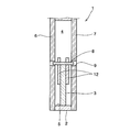
- FIG. 2 is a cross-sectional view taken along line II-II shown in FIG. It is a figure for demonstrating the effect
- the present invention relates to a dynamic damper that is attached to a rotating member that rotates by receiving torque and absorbs or attenuates torque fluctuations acting on the rotating member or torsional vibration caused by the torque fluctuation. Therefore, the dynamic damper according to the present invention can be provided on a crankshaft of an internal combustion engine mounted on a vehicle, an input shaft or a drive shaft of a transmission, or a rotating member that is attached to these and rotates integrally therewith. . According to the present invention, when torque fluctuation or torsional vibration resulting from this is applied to the rotating member described above, a rolling element corresponding to a weight (mass) that moves in a direction opposite to the rotational direction, that is, a damper mass.
- the rolling element can be accommodated in a rolling chamber in which a rolling surface having a predetermined constant curvature is formed and held on the rotating member described above.
- a sphere configured to resonate with the torsional vibration order of the rotating member and roll on the rolling surface that is, a ball or a cylindrical roller can be used.
- the rolling element absorbs the torsional vibration order of the rotating member by resonating the pendulum motion order of the rolling element to the torsional vibration order of the rotating member according to the torque fluctuation acting on the rotating member or the torsional vibration resulting therefrom. Since it is for damping, the pendulum motion order of the rolling element is designed to be equal to the torsional vibration order of the target rotating member.
- the rolling element is configured such that the center of gravity is eccentric with respect to the geometric center, and the so-called offset of the center of gravity is provided with an eccentric weight on at least a part of the rolling element, or At least a part of the rolling element can be cut out, or the rolling element can be formed by increasing the thickness of one side in the diameter direction and reducing the other side.
- an appropriate means or method can be used for offset of the center of gravity with respect to the geometric center of the rolling element.
- the position of the center of gravity of the rolling element is the center of curvature of the rolling surface across the center of gravity when the distance from the center of curvature of the rolling element that changes with rolling to the center of gravity of the rolling element is the shortest.
- the geometric center of the rolling element is arranged on the opposite side. Further, the distance at which the center of gravity is offset with respect to the geometric center of the rolling element, in other words, the offset amount is, in short, the distance from the center of curvature of the rolling surface to the center of gravity of the rolling element as described above.
- the instantaneous center of the center of gravity of the rolling element changes, and at least a part of the orbit of the center of gravity is a cycloid curve or a simulated pseudo This is the distance at which a typical cycloid curve can be drawn. Therefore, this can be obtained in advance by experiments or simulations.
- the moment of the center of gravity of the rolling element depends on the distance that the rolling surface has rolled.
- the center changes. That is, according to the present invention, when the rolling element rolls on the rolling surface according to the vibration angle of the rotating member, the moving locus of the center of gravity of the rolling element increases as the distance that the rolling element rolls on the rolling surface increases. The radius of curvature at each point gradually decreases.
- At least a part of the trajectory of the center of gravity of the rolling element can draw a cycloid curve or a pseudo cycloid curve approximated thereto according to the so-called rolling amount of the rolling element.
- the instantaneous center of the center of gravity of the rolling element changes. To do.
- the radius of curvature at each point of the moving locus of the center of gravity of the rolling element gradually decreases. Therefore, when the rolling element rolls, at least a part of the trajectory of the center of gravity can draw a cycloid curve or a pseudo cycloid curve approximated thereto.
- the rolling element moves pendulum like a cycloid pendulum or pseudo cycloid pendulum, so when designing the pendulum motion order of the rolling element, torque fluctuations acting on the rolling element or torsional vibration caused by this
- the order can be designed without taking into consideration the vibration angle ⁇ of the rolling element according to the above. Therefore, regardless of the magnitude of the vibration angle with respect to the rotation direction of the rotating member, the difference between the designed pendulum motion order of the rolling element and the actual pendulum motion order of the rolling element can be reduced.
- the pendulum motion order of the rolling element can be made to resonate with the torsional vibration order of the rotating member, and the torsional vibration order of the rotating member can be absorbed or attenuated.
- the center of gravity of the rolling element is decentered with respect to its geometric center, and at least a part of the orbit of the center of gravity is made a cycloid curve or a pseudo cycloid curve similar to this to improve the vibration damping performance. it can.
- a guide mechanism for rolling the rolling element without sliding against the rolling surface.
- a protrusion projecting in the axial direction of the rotating member is provided on one of the outer peripheral edge of the rolling element and a surface parallel to the rotating surface of the rotating member on the inner surface of the rolling chamber.
- a guide groove for loosely fitting the protrusion can be formed, for example, along the hypocycloid of the rolling element. Further, by forming the guide groove to a predetermined length, it is possible to restrict the range in which the rolling element rolls on the rolling surface.
- the guide mechanism configured as described above, it is possible to prevent or suppress the so-called sliding motion of the rolling element with respect to the rolling surface and to cause the rolling element to perform a pendulum motion at the designed pendulum motion order. Further, by restricting the range in which the rolling element rolls on the rolling surface by the guide mechanism, the rolling element can be disposed inside the rolling chamber and on the outer peripheral side of the rotating member. That is, the moment of inertia of the dynamic damper according to the present invention can be relatively increased by arranging the rolling elements on the outer peripheral side of the rotating member. Further, the rolling element can be moved in a pendulum manner within a range restricted by the guide mechanism.
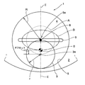
- FIG. 1 schematically shows an example in which the dynamic damper according to the present invention is applied to a rotating member.
- FIG. 1 shows a state in which one dynamic damper 1 is viewed from a direction perpendicular to a rotation surface of a rotating member 2 to which the dynamic damper 1 is attached.
- the dynamic damper 1 according to the present invention is provided integrally with a rotating member 2 to be subjected to vibration damping, to which torque is input or torque is output.
- a rolling chamber 4 for accommodating the rolling elements 3 is formed inside the rotating member 2 and in the vicinity of the outer peripheral edge thereof.
- the rolling chamber 4 is formed in, for example, a hollow cylindrical shape, and an axis passing through the geometric center thereof is parallel to the rotation axis of the rotating member 2.
- a rolling surface 5 having a predetermined curvature is formed on the inner peripheral surface.
- the geometric center of the rolling chamber 4 and the curvature center 5 a of the rolling surface 5 coincide with each other.
- the rolling element 3 is formed in a cylindrical shape whose ratio of the outer diameter r to the inner diameter R of the rolling chamber 4 is 1 ⁇ 2, and the axis passing through the geometric center 3 a is the rotation member 2. It is parallel to the rotation axis. Since the rolling element 3 resonates the pendulum motion order with the torsional vibration order of the rotating member 2 and absorbs or attenuates the torsional vibration order of the rotating member 2, the pendulum motion order of the rolling element 3 is It is designed to be equal to the torsional vibration order of the rotating member 2.
- the rolling element 3 is configured such that the center of gravity g is decentered with respect to the geometric center 3a, that is, the center of gravity g is offset by a predetermined distance with respect to the geometric center 3a. ing.
- the offset of the center of gravity g is that an eccentric weight (mass) is provided on at least a part of the rolling element 3, or at least a part of the rolling element 3 is notched, or the thickness of the rolling element 3 is changed in the diameter direction. What is necessary is just to comprise so that the gravity center g of the rolling element 3 may be eccentric with respect to the geometrical center 3a by thickening one side and making the other side thin. Further, in the example shown in FIG.
- the center of gravity g of the rolling element 3 is geometric when the rolling element 3 is disposed inside the rolling chamber 4 and on the outermost peripheral side of the rotating member 2. It is arranged closer to the center of curvature 5a of the rolling surface 5 than the center 3a.
- the distance by which the center of gravity g is offset with respect to the geometric center 3a of the rolling element 3 is that when the rolling element 3 rolls on the rolling surface 5 having a predetermined curvature, At least a part of the trajectory of the center of gravity g is a distance at which a cycloid curve or a pseudo cycloid curve approximated thereto can be drawn. Therefore, this can be obtained in advance by experiments, simulations, or the like.
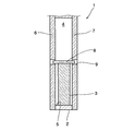
- FIG. 2 is a sectional view taken along the line II-II shown in FIG.
- lid members 6 and 7 are provided so as to cover the open end of the rolling chamber 4 formed in a hollow cylindrical shape.
- the rotating member 2 is integrated.
- the rolling chamber 4 may be formed in the rotating member 2 in a bottomed cylindrical shape, and the open end may be covered with a lid member.
- a protrusion 8 protruding in the axial direction of the rotating member 2 is provided on the outer peripheral edge of the rolling element 3.
- a guide groove 9 for loosely fitting the protrusion 8 is provided so as to penetrate the surface of the lid member 6, 7 on the side of the rolling chamber 4 or the lid member 6, 7.
- the guide groove 9 is formed such that when the distance from the center of curvature 5 a of the rolling surface 5 to the center of gravity g of the rolling element 3 is the shortest, the center of curvature 5 a of the rolling surface 5 and the rolling element. 3 is formed over a predetermined length in a direction orthogonal to a straight line connecting the three centroids g.
- the protrusion 8 or the guide groove 9 is formed along a so-called hypocycloid, and these serve as a guide mechanism. Therefore, when the protrusion 8 is loosely fitted in the guide groove 9, the sliding motion of the rolling element 3 is prevented or suppressed, and the rolling element 3 rolls on the rolling surface 5.
- the guide groove 9 is formed to be relatively short with respect to the radius of the rolling chamber 4, so that the rolling element 3 forms the rolling surface 5 by the end of the guide groove 9.
- the rolling distance is regulated.
- the rolling element 3 can be disposed inside the rolling chamber 4 on the outer peripheral side of the rotating member 2 by the guide mechanism configured as described above. Therefore, when vibration in the rotation direction acts on the rotating member 2, the rolling element 3 is rotated by the guide mechanism from the state where the distance from the center of curvature 5a of the rolling surface 5 to the center of gravity g of the rolling element 3 is the shortest.
- the pendulum can be moved by rolling the rolling surface 5 in a range until the moving distance is regulated.
- the movement trajectory of the geometric center 3 a associated with the rolling of the rolling element 3 is shown using a dotted line A
- the movement trajectory of the center of gravity g of the rolling element 3 is shown using a broken line B. It is shown.
- the rolling element 3 moves to the outer peripheral edge side in the radial direction of the rotating member 2 in the rolling chamber 4.
- the vibration angle ⁇ (sometimes referred to as an amplitude angle) of the rolling element 3 is 0 °
- the rolling element 3 As shown in FIG. 3, it is mainly disposed at a so-called maximum bulging position in the rolling chamber 4.
- the rolling element 3 is The rolling surface 5 rolls in the direction opposite to the rotation direction of the rotating member 2.
- the rolling distance of the rolling element 3, in other words, the vibration angle ⁇ of the rolling element 3 changes according to the torque fluctuation acting on the dynamic damper 1 or the rotating member 2 or the magnitude of torsional vibration resulting therefrom as described above. To do. Further, as described above, since the sliding motion of the rolling element 3 is prevented or suppressed by the guide mechanism, the rolling element 3 rolls on the rolling surface 5 without the sliding motion.
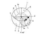
- FIG. 4 shows a case where the vibration angle ⁇ of the rolling element 3 is 30 °.
- the vibration angle ⁇ of the rolling element 3 increases from 0 ° to 30 °, the rolling element 3 that rolls on the rolling surface 5 as described above increases with the increase of the vibration angle ⁇ . Since the instantaneous center of the center of gravity changes and the rolling element 3 rolls on the rolling surface 5 having a constant curvature, the radius of curvature at each point of the moving locus of the center of gravity of the rolling element 3 gradually decreases.
- FIG. 5 shows a case where the vibration angle ⁇ of the rolling element 3 is 45 °.
- the vibration angle ⁇ of the rolling element 3 increases from 0 ° to 45 °, the instantaneous center of the center of gravity of the rolling element 3 that rolls on the rolling surface 5 as the vibration angle ⁇ increases. Since the rolling element 3 rolls on the rolling surface 5 having a constant curvature, the radius of curvature at each point of the movement locus of the center of gravity of the rolling element 3 gradually decreases.
- the vibration angle ⁇ is regulated.
- the torque fluctuation of the rotating member 2 input to the dynamic damper 1 or the magnitude of torsional vibration caused by the torque fluctuation that is, the vibration angle ⁇ of the rolling element 3 increases, so
- the instantaneous center of the center of gravity of the rolling element 3 changes according to the amount of rolling.
- the vibration angle ⁇ of the rolling element 3 increases, the radius of curvature at each point of the movement locus of the center of gravity of the rolling element 3 gradually decreases, and at least a part of the trajectory of the center of gravity g of the rolling element 3 is reduced as shown in FIG. Or, as shown by the solid line C in FIG. 5, a cycloid curve or a pseudo cycloid curve approximated thereto can be drawn.
- the rolling element 3 is arranged in the rolling chamber 4 as described above, and the center of gravity g of the rolling element 3 is decentered toward the curvature center 5a side of the rolling surface 5 from the geometric center 3a. At least a part of the trajectory of the center of gravity g of the rolling element 3 accompanying the rolling can draw a cycloid curve or a pseudo cycloid curve approximated thereto. That is, since the rolling element 3 moves like a cycloid pendulum or a pseudo cycloid pendulum, it is not necessary to consider the vibration angle ⁇ of the rolling element 3 when designing the order.
- the difference between the designed pendulum motion order of the rolling element 3 and the actual pendulum motion order of the rolling element 3 can be reduced.
- the torsional vibration order acting on the rotating member 2 equal to the pendulum motion order of the rolling element 3 can be absorbed or attenuated regardless of the vibration angle ⁇ of the rotating member 2 or the rolling element 3. That is, the center of gravity g of the rolling element 3 is decentered with respect to the geometric center 3a, and at least a part of the trajectory of the center of gravity g is a cycloid curve or a pseudo cycloid curve approximated thereto. Vibration performance can be improved.
- the so-called sliding motion of the rolling element 3 with respect to the rolling surface 5 is prevented or suppressed by the guide mechanism, and the rolling element 3 can be moved in a pendulum motion at the designed pendulum motion order.
- the rolling element 3 can be disposed inside the rolling chamber 4 on the outer peripheral side in the radial direction of the rotating member 2, and the moment of inertia of the dynamic damper 1 can be relatively increased.
- the rolling distance of the rolling element 3 can be regulated, and the rolling element 3 can be caused to perform a pendulum motion within a range in which the rolling surface 5 can roll.
- FIG. 6 shows an example in which the rolling element shown in FIG. 1 is improved.
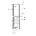
- FIG. 7 is a sectional view taken along line VII-VII shown in FIG.
- the example shown in FIGS. 6 and 7 is an example in which the center of gravity g is decentered with respect to the geometric center 3 a of the rolling element 3 by providing a through hole 10 in a part of the rolling element 3. is there.
- the rolling element 3 is configured such that the ratio of the outer diameter r of the rolling element 3 to the inner diameter R of the rolling chamber 4 is 1 ⁇ 2.
- a through hole 10 having an axis parallel to the axial direction of the rolling element 3 is formed.
- the through hole 10 is formed in a circular shape, and the diameter thereof is shorter than the radius of the rolling element 3.
- a protrusion 8 protruding in the axial direction of the rotating member 2 is provided on the outer peripheral edge of the rolling element 3, and a guide groove 9 for loosely fitting the protrusion 8 is provided as a lid.
- the members 6 and 7 are provided so as to penetrate the surface of the rolling chamber 4 or the lid members 6 and 7. Therefore, the rolling element 3 is prevented or suppressed from sliding motion by the guide mechanism including the protrusion 8 and the guide groove 9, and rolls on the rolling surface 5 without sliding.
- the guide groove 9 is formed to be relatively short with respect to the diameter of the rolling chamber 4, and therefore, the rolling distance or range of the rolling element 3 by the end of the guide groove 9.
- the rolling element 3 is arranged inside the rolling chamber 4 and on the outer peripheral side of the rotating member 2.
- the rolling element 3 has a rolling surface 5 that is more than the geometric center 3a of the rolling element 3 as in the example shown in FIG.
- the center of gravity g is arranged on the side of the center of curvature 5a.
- the size or position of the through hole 10 described above is basically arranged such that the center of gravity g of the rolling element 3 is offset with respect to the geometric center 3a and is arranged in the rolling chamber 4 as described above.
- the rolling element 3 rolls on the rolling surface 5, it is set so that at least a part of the trajectory of the center of gravity g becomes a cycloid curve or a pseudo cycloid curve approximated thereto. Therefore, the size or position of the through hole 10 can be obtained in advance by experiments, simulations, or the like.
- the rotational speed of the rotating member 2 to be controlled is increased or decreased, and a torque fluctuation of a certain magnitude or torsional vibration resulting therefrom acts on the rotating member 2, which is dynamic.
- the rolling element 3 rolls on the rolling surface 5 in the direction opposite to the rotation direction of the rotating member 2.
- the rolling distance, that is, the vibration angle ⁇ of the rolling element 3 varies according to the torque fluctuation acting on the dynamic damper 1 or the rotating member 2 or the torsional vibration resulting therefrom as described above.
- the rolling element 3 rolls on the rolling surface 5 having a constant curvature as the vibration angle ⁇ of the rotating member 2 or the rolling element 3 increases, and the radius of curvature at each point of the moving locus of the center of gravity of the rolling element 3 is increased. Similar to the example shown in FIG. 3 to FIG. That is, as the vibration angle ⁇ of the rolling element 3 increases, at least a part of the trajectory of the center of gravity g of the rolling element 3 can draw a cycloid curve or a pseudo cycloid curve approximated thereto.
- FIG. 8 shows an example in which the configuration shown in FIG. 6 is improved.
- FIG. 9 shows a cross-sectional view along the line IX-IX shown in FIG.
- an eccentric weight (mass) member 11 is provided on a part of the rolling element 3 so that the mass in the diametrical direction is asymmetric with respect to the geometric center 3a.
- the center of gravity g is eccentric with respect to the geometric center 3a of the rolling element 3.
- the rolling element 3 is configured such that the ratio of the outer diameter r of the rolling element 3 to the inner diameter R of the rolling chamber 4 is 1 ⁇ 2.
- a weight member 11 is provided on a part of the weight member 11.
- the weight member 11 is formed in a semicircular shape with respect to the rolling element 3, and is provided integrally with a surface parallel to the rotation surface of the rotating member 2 in the rolling element 3. It has been.
- a protrusion 8 that protrudes in the axial direction of the rotating member 2 is provided on the outer peripheral edge of the rolling element 3, and a guide groove 9 that loosely fits this protrusion 8 is rolled in the lid members 6 and 7. It is provided so as to penetrate the surface on the chamber 4 side or the lid members 6 and 7. Therefore, the rolling element 3 is prevented or suppressed from sliding motion by the guide mechanism including the protrusion 8 and the guide groove 9, and rolls on the rolling surface 5 without sliding.
- the guide groove 9 is formed to be relatively short with respect to the diameter of the rolling chamber 4. Therefore, the rolling distance of the rolling element 3, that is, the end of the guide groove 9, that is, The range is now regulated. Further, by this guide mechanism, the rolling element 3 is arranged inside the rolling chamber 4 and on the outer peripheral side of the rotating member 2.
- the rolling element 3 When the vibration angle ⁇ of the rolling element 3 is 0 ° by the guide mechanism, the rolling element 3 has a curvature of the rolling surface 5 with respect to the geometric center 3a of the rolling element 3 as in the example shown in FIG.
- the center of gravity g is arranged on the center 5a side.
- the shape, number, or mass of the weight member 11 provided on the rolling element 3 is basically the offset of the center of gravity g of the rolling element 3 with respect to the geometric center 3a, and the rolling chamber as described above.
- the rolling element 3 arranged at 4 rolls on the rolling surface 5 at least a part of the trajectory of the center of gravity g is set to be a cycloid curve or a pseudo cycloid curve approximated thereto. . Therefore, the shape, number, or mass of the weight member 11 can be obtained in advance by experiment, simulation, or the like.
- the rolling element 3 is rotated according to the vibration angle ⁇ .
- the rolling surface 5 rolls in a direction relatively opposite to the rotation direction 2. Therefore, the rolling element 3 rolls on the rolling surface 5 having a constant curvature as the vibration angle ⁇ of the rotating member 2 or the rolling element 3 increases, and the radius of curvature at each point of the moving locus of the center of gravity of the rolling element 3 is increased. Similar to the example shown in FIG. 3 to FIG. That is, as the vibration angle ⁇ of the rolling element 3 increases, at least a part of the trajectory of the center of gravity g of the rolling element 3 can draw a cycloid curve or a pseudo cycloid curve approximated thereto.
- FIG. 10 shows an example in which the configuration shown in FIGS. 6 and 8 is improved.
- FIG. 11 is a sectional view taken along line XI-XI shown in FIG.
- the example shown here is an example in which the shape of the weight member that decenters the center of gravity g of the rolling element 3 from the geometric center 3a is improved.
- the weight (mass) member 12 shown in FIGS. 10 and 11 has a circular rotation of the rolling element 3 when at least a part of the rolling element 3 is arranged at a so-called bulging position. It is formed in a semicircular shape so as to face the surface, and is integrally provided on the rotating surface of the inner rolling element 3 in the radial direction of the rotating member 2. And at least another part is formed in the semicircle shape which protruded inward in the radial direction of the rotation member 2, as shown in FIG.
- the rolling element 3 provided with the weight member 12 configured as described above is similar to the example shown in FIG.
- the center of gravity g is arranged closer to the center of curvature 5a of the rolling surface 5 than the geometric center 3a.
- the shape, number, or mass of the weight member 12 provided on the rolling element 3 is basically the offset of the center of gravity g of the rolling element 3 with respect to the geometric center 3a, as described above.
- the rolling element 3 arranged in the rolling chamber 4 rolls on the rolling surface 5 at least a part of the trajectory of the center of gravity g becomes a cycloid curve or a pseudo cycloid curve approximated thereto. Is set. Therefore, the shape, number, or mass of the weight member 12 can be obtained in advance by experiments or simulations.
- the rolling element 3 rolls on the rolling surface 5 having a constant curvature according to the vibration angle ⁇ . Then, as the vibration angle ⁇ of the rolling element 3 increases, the radius of curvature at each point of the movement path of the center of gravity of the rolling element 3 gradually decreases in the same manner as in the examples shown in FIGS. At least a part of the trajectory can be a cycloid curve or a pseudo cycloid curve approximated thereto.
- the rolling element 3 is arranged in the rolling chamber 4 having a predetermined curvature as described above, and the center of gravity g of the rolling element 3 is geometrically arranged. At least a part of the trajectory of the center of gravity g associated with the rolling of the rolling element 3 is made to be a cycloid curve or a center of the cycloid curve. An approximate pseudo cycloid curve can be drawn. That is, since the rolling element 3 performs a pendulum motion like a cycloid pendulum or a pseudo cycloid pendulum, it is not necessary to consider the vibration angle of the rolling element 3 when designing the order.
- the difference between the designed pendulum motion order of the rolling element 3 and the actual pendulum motion order of the rolling element 3, that is, the deviation can be reduced.
- the torsional vibration order acting on the rotating member 2 is made to resonate with the torsional vibration order acting on the rotating member 2, and the torsional vibration acting on the rotating member 2.
- the order can be absorbed or attenuated. That is, the center of gravity g of the rolling element 3 is decentered with respect to the geometric center 3a, and at least a part of the trajectory of the center of gravity g is a cycloid curve or a pseudo cycloid curve approximated thereto. Vibration performance can be improved.
- the so-called sliding motion of the rolling element 3 with respect to the rolling surface 5 is prevented or suppressed by the guide mechanism, and the rolling element 3 can be moved in a pendulum motion with the designed pendulum motion order.
- the rolling element 3 can be disposed inside the rolling chamber 4 on the outer peripheral side in the radial direction of the rotating member 2, and the moment of inertia of the dynamic damper 1 can be relatively increased.
- the rolling distance of the rolling element 3 can be regulated, and the rolling element 3 can be caused to perform a pendulum motion within a range in which the rolling surface 5 can roll.
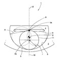
- FIG. 12 shows an example in which the rolling chamber shown in FIG. 1 is improved.
- FIG. 13 is a sectional view taken along line XIII-XIII shown in FIG.
- the dynamic damper 1 absorbs or attenuates the torsional vibration order of the rotating member 2 by causing the pendulum motion order of the rolling element 3 to resonate with the torsional vibration order of the target rotating member 2. Is. Further, a centrifugal force corresponding to the rotational speed acts on the rolling element 3 as the rotational speed of the rotating member 2 increases, and the centrifugal force moves to the outer peripheral side in the radial direction of the rotating member 2.
- a predetermined curvature is formed in which a center of curvature is provided on the inner side in the radial direction of the rotating member 2 and bulges outward in the radial direction of the rotating member 2.
- the rolling chamber 4 is formed in a portion delimited by a constant arc and a straight line orthogonal to a straight line connecting the center of curvature of the arc and the geometric center of the rotating member 2.
- An arc surface having a constant curvature on the inner peripheral surface of the rolling chamber 4 is a rolling surface 5.
- the rolling element 3 is configured such that the ratio of the outer diameter r of the rolling element 3 to the radius of curvature of the rolling surface 5 is 1 ⁇ 2.
- the shown weight member 11 is integrally provided.
- a protrusion 8 is provided on the outer peripheral edge of the rolling element 3, and a guide groove 9 for loosely fitting the protrusion 8 is provided in the rolling chambers of the lid members 6 and 7. It is provided so as to penetrate the four-side surface or the lid members 6 and 7.
- the guide groove 9 is formed to be relatively shorter than the diameter of the rolling chamber 4, that is, a length corresponding to twice the radius of curvature of the rolling surface 5.
- the rolling distance of the rolling element 3, that is, the range in which the rolling element 3 can roll on the rolling surface 5 is regulated.
- the rolling element 3 is arranged inside the rolling chamber 4 and on the outer peripheral side of the rotating member 2.
- the rolling element 3 has a rolling surface that is more than the geometric center 3a of the rolling element 3 as in the example shown in FIG.
- the center of gravity g is arranged on the 5 curvature center 5a side.
- the rotational speed of the rotating member 2 to be controlled is increased or decreased, and a torque fluctuation of a certain magnitude or torsional vibration resulting therefrom acts on the rotating member 2, which is dynamic.
- the rolling element 3 rolls on the rolling surface 5 in the direction opposite to the rotation direction of the rotating member 2 according to the vibration angle.
- the rolling range of the rolling element 3 is restricted by the guide mechanism, the rolling surface 5 with a constant curvature is rolled in accordance with the vibration angle ⁇ of the rolling element 3 within the restricted range.
- the instantaneous center of the center of gravity of the moving body 3 changes.
- the rolling element 3 can draw a cycloid curve or a pseudo cycloid curve approximated to the cycloid curve at least part of the trajectory of the center of gravity g within the rolling range restricted by the guide mechanism.
- the rolling element 3 is placed on the outer peripheral side in the rolling chamber 4 and in the radial direction of the rotating member 2.
- the dynamic damper 1 can be reduced in size.
- the divergence between the designed pendulum motion order of the rolling element 3 and the actual pendulum motion order of the rolling element 3 can be reduced regardless of the vibration angle ⁇ of the rotating member 2 or the rolling element 3.
- the torsional vibration order acting on the rotating member 2 is made to resonate with the torsional vibration order acting on the rotating member 2, and the torsional vibration acting on the rotating member 2.
- the order can be absorbed or attenuated. That is, the center of gravity g of the rolling element 3 is decentered with respect to the geometric center 3a, and the trajectory of the center of gravity g is changed to a cycloid curve or a pseudo cycloid curve approximated thereto, thereby improving the damping performance. it can.
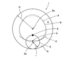
- FIG. 14 shows another example of the dynamic damper according to the present invention.
- the example shown here is an example in which the ratio of the outer diameter r of the rolling element 3 to the radius of curvature of the rolling surface 5 is 1/3.
- the rolling chamber 4 is formed in a circular shape having a predetermined curvature, and the rolling surface 5 having a constant curvature is formed on the inner peripheral surface thereof. Is formed. Inside the rolling chamber 4, the rolling element 3 is accommodated so that the rolling surface 5 can roll.
- the ratio of the outer diameter r to the inner diameter R is configured to be 1/3.
- the rolling element 3 is provided with a protrusion 8 that protrudes in the axial direction of the rotating member 2 on the outer peripheral edge of the rolling element 3.
- a lid member is provided so as to cover the open end of the rolling chamber 4 formed in a hollow cylindrical shape, and the rolling chamber 4 side of this lid member is provided.
- a guide groove for loosely fitting the protrusion 8 is provided so as to penetrate the surface or the lid member.
- the rolling element 3 is offset so that the center of gravity g is eccentric with respect to the geometric center 3a, that is, the center of gravity g is offset from the geometric center 3a by a predetermined distance. It is configured.
- the offset of the center of gravity g with respect to the geometric center 3a is as described above, in which at least a part of the rolling element 3 is provided with a weight, or at least a part of the rolling element 3 is notched, or the rolling element. 3 may be configured such that one side is increased in the diameter direction and the other side is decreased.
- the rolling element 3 comprised in this way is arrange
- the angle ⁇ is 0 °
- the center of gravity g is arranged closer to the center of curvature 5a of the rolling surface 5 than the geometric center 3a of the rolling element 3 as in the example shown in FIG. It has become.
- the distance from the geometric center 3a of the rolling element 3 to the center of gravity g is that the rolling element 3 has a vibration angle ⁇ of 0 °, that is, as described above.
- FIG. 14 shows the trajectory of the center of gravity g of the rolling element 3 configured as described above using the broken line B.
- a torque fluctuation of a certain magnitude or a torsional vibration resulting therefrom is applied to the rotating member 2, and when this is input to the dynamic damper 1, the rolling element 3 rolls the rolling surface 5 in the direction opposite to the rotation direction of the rotating member 2 in accordance with the vibration angle ⁇ .
- the rolling element 3 has its center of gravity g decentered at a predetermined distance from the geometric center 3a.
- the path of the center of gravity g is indicated by a solid line C in FIG.
- the radius of curvature at each point of the trajectory gradually decreases, and at least a part of the trajectory of the center of gravity g draws a cycloid curve or a pseudo cycloid curve approximated thereto. Can do.
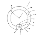
- FIG. 15 shows still another example of the dynamic damper according to the present invention.
- the example shown here is an example in which the ratio of the outer diameter r of the rolling element 3 to the radius of curvature of the rolling surface 5 is 1 ⁇ 4.
- the rolling chamber 4 is formed in a circular shape with a predetermined curvature, and the rolling surface 5 with a constant curvature is formed on the inner peripheral surface thereof. Is formed.
- a rolling element 3 is accommodated in the rolling chamber 4 so that the rolling surface 5 can roll, and the rolling element 3 has a radius of curvature of the rolling surface 5 or an inner diameter R of the rolling chamber 4.
- the ratio of the outer diameter r is 1 ⁇ 4.
- the rolling element 3 is provided with a protrusion 8 that protrudes in the axial direction of the rotating member 2 on the outer peripheral edge of the rolling element 3.
- a lid member is provided so as to cover the opening end of the rolling chamber 4 formed in a hollow cylindrical shape, and the rolling chamber 4 side of this lid member is provided.
- a guide groove for loosely fitting the protrusion 8 is provided so as to penetrate the surface or the lid member.
- the rolling element 3 is offset so that the center of gravity g is eccentric with respect to the geometric center 3a, that is, the center of gravity g is offset from the geometric center 3a by a predetermined distance. It is configured.
- the offset of the center of gravity g with respect to the geometric center 3a is as described above, in which at least a part of the rolling element 3 is provided with a weight, or at least a part of the rolling element 3 is notched, or the rolling element. 3 may be configured such that one side is increased in the diameter direction and the other side is decreased.
- the rolling element 3 comprised in this way is arrange
- the angle ⁇ is 0 °
- the center of gravity g is arranged closer to the center of curvature 5a of the rolling surface 5 than the geometric center 3a of the rolling element 3 as in the example shown in FIG. It has become.
- the distance from the geometric center 3a of the rolling element 3 to the center of gravity g is that the rolling element 3 has a vibration angle ⁇ of 0 °, that is, as described above. Is a distance for drawing a cycloid curve or a pseudo cycloid curve approximated to the cycloid curve when the roller rolls from the most bulging position arranged in the rolling chamber 4, Therefore, this can be obtained in advance by experiments or simulations.
- FIG. 15 shows the trajectory of the center of gravity g of the rolling element 3 configured as described above using a broken line B.
- a torque fluctuation of a certain magnitude or a torsional vibration resulting therefrom is applied to the rotating member 2, and when this is input to the dynamic damper 1, the rolling element 3 rolls the rolling surface 5 in the direction opposite to the rotation direction of the rotating member 2 according to the vibration angle.
- the center of gravity g of the rolling element 3 is eccentric with a predetermined distance from the geometric center 3a, the trajectory of the center of gravity g is indicated by a solid line C in FIG.
- the radius of curvature at each point of the trajectory gradually decreases, and at least a part of the trajectory of the center of gravity g draws a cycloid curve or a pseudo cycloid curve approximated thereto. Can do.
- the rolling element 3 is disposed in the rolling chamber 4 as described above, and the center of gravity g of the rolling element 3 is set to be a rolling surface more than the geometric center 3a. At least a part of the trajectory of the center of gravity g of the rolling element 3 accompanying the rolling is shown by using a solid line C in FIGS. 14 and 15. As described above, a cycloid curve or a pseudo cycloid curve approximated thereto is drawn. That is, since the rolling element 3 performs a pendulum motion like a cycloid pendulum or a pseudo cycloid pendulum, it is not necessary to consider the vibration angle of the rolling element 3 when designing the order.
- the difference between the designed pendulum motion order of the rolling element 3 and the actual pendulum motion order of the rolling element 3 can be reduced.
- the torsional vibration order acting on the rotating member 2 is made to resonate with the torsional vibration order acting on the rotating member 2, and the torsional vibration acting on the rotating member 2.
- the order can be absorbed or attenuated. That is, the center of gravity g of the rolling element 3 is decentered with respect to the geometric center 3a, and at least a part of the trajectory of the center of gravity g is a cycloid curve or a pseudo cycloid curve approximated thereto. Vibration performance can be improved.
- the so-called sliding motion of the rolling element 3 with respect to the rolling surface 5 is prevented or suppressed by the guide mechanism, and the rolling element 3 can be moved in a pendulum motion at the designed pendulum motion order.
- the rolling element 3 can be disposed inside the rolling chamber 4 on the outer peripheral side in the radial direction of the rotating member 2, and the moment of inertia of the dynamic damper 1 can be relatively increased.
- the rolling distance of the rolling element 3 can be regulated, and the rolling element 3 can be moved in a pendulum manner within a range in which the rolling surface 5 can roll.
- the center of gravity of the rolling element is decentered with respect to the geometric center, and the rolling element is caused to roll with respect to the rolling surface having a constant curvature by the guide mechanism.
- the orbit of the center of gravity can be made to be a cycloid curve or a pseudo cycloid curve approximated thereto.
- the torsional vibration order of the rotating member is made to resonate with the torsional vibration order of the rotating member, and the torsional vibration order of the rotating member is absorbed or attenuated. be able to. That is, according to the present invention, a pseudo cycloid dynamic damper can be realized.
- the rolling element can be disposed inside the rolling chamber and on the outer peripheral side in the radial direction of the rotating member. Can regulate the range of rolling on the rolling surface. Therefore, it is possible to reduce the size of the dynamic damper.
Landscapes
- Engineering & Computer Science (AREA)
- General Engineering & Computer Science (AREA)
- Physics & Mathematics (AREA)
- Acoustics & Sound (AREA)
- Aviation & Aerospace Engineering (AREA)
- Mechanical Engineering (AREA)
- Transmission Devices (AREA)
- Rolling Contact Bearings (AREA)
- Vibration Prevention Devices (AREA)
- Retarders (AREA)
Abstract
Description
Claims (4)
- 回転する回転部材に設けられた転動室に、前記回転部材に作用するトルク変動に応じて転動する転動体を収容するとともに前記転動室の内周面に前記転動体が転動する転動面が形成されているダイナミックダンパにおいて、
前記転動面は一定曲率の円弧面として形成され、
前記転動体は、前記転動面よりも曲率半径が小さい円形断面を備えるとともにその転動体の重心はその幾何学的な中心に対して偏心しており、かつ
その転動体を前記転動面に対して転動させるガイド機構を備えている
ことを特徴とするダイナミックダンパ。 - 前記転動体は、その転動にともなう前記転動面の曲率中心から前記転動体の重心までの距離が最も短くなった場合に、その重心を挟んで前記転動面の曲率中心とは反対側に前記転動体の幾何学的な中心が配置されることを特徴とする請求項1に記載のダイナミックダンパ。
- 前記ガイド機構は、前記転動体の外周縁と前記転動室の内部における前記回転部材の回転面に平行な面とのいずれか一方に設けられ、前記回転部材の軸線方向に突出した突部と、いずれか他方に設けられ、その突部を遊嵌するガイド溝とを備えていることを特徴とする請求項1に記載のダイナミックダンパ。
- 回転する回転部材に設けられた転動室に、前記回転部材に作用するトルク変動に応じて転動する転動体を収容するとともに前記転動室の内周面に前記転動体が転動する転動面が形成されているダイナミックダンパにおいて、
前記転動室の内径に対する前記転動体の外径の比率が1/2であって、
前記転動体は、その重心がその幾何学的な中心に対して偏心されるとともに、前記転動面の曲率中心から前記転動体の重心までの距離が最も短くなった場合に、その重心を挟んで前記転動面の曲率中心とは反対側に前記転動体の幾何学的な中心が配置され、かつ
前記転動面の曲率中心から前記転動体の重心までの距離が最も短くなった場合における前記転動面の曲率中心と前記転動体の重心とを結んだ直線に対して直交する向きに、前記転動体を前記転動面に対して転動させるガイド機構を備えている
ことを特徴とするダイナミックダンパ。
Priority Applications (5)
| Application Number | Priority Date | Filing Date | Title |
|---|---|---|---|
| US13/637,485 US9080637B2 (en) | 2010-04-14 | 2010-04-14 | Dynamic damper |
| JP2012510502A JP5382207B2 (ja) | 2010-04-14 | 2010-04-14 | ダイナミックダンパ |
| DE112010005482.7T DE112010005482B4 (de) | 2010-04-14 | 2010-04-14 | Dynamischer Dämpfer |
| CN201080066217.2A CN102893054B (zh) | 2010-04-14 | 2010-04-14 | 动力减振器 |
| PCT/JP2010/056654 WO2011128988A1 (ja) | 2010-04-14 | 2010-04-14 | ダイナミックダンパ |
Applications Claiming Priority (1)
| Application Number | Priority Date | Filing Date | Title |
|---|---|---|---|
| PCT/JP2010/056654 WO2011128988A1 (ja) | 2010-04-14 | 2010-04-14 | ダイナミックダンパ |
Publications (1)
| Publication Number | Publication Date |
|---|---|
| WO2011128988A1 true WO2011128988A1 (ja) | 2011-10-20 |
Family
ID=44798381
Family Applications (1)
| Application Number | Title | Priority Date | Filing Date |
|---|---|---|---|
| PCT/JP2010/056654 Ceased WO2011128988A1 (ja) | 2010-04-14 | 2010-04-14 | ダイナミックダンパ |
Country Status (5)
| Country | Link |
|---|---|
| US (1) | US9080637B2 (ja) |
| JP (1) | JP5382207B2 (ja) |
| CN (1) | CN102893054B (ja) |
| DE (1) | DE112010005482B4 (ja) |
| WO (1) | WO2011128988A1 (ja) |
Cited By (3)
| Publication number | Priority date | Publication date | Assignee | Title |
|---|---|---|---|---|
| JP2013174298A (ja) * | 2012-02-24 | 2013-09-05 | Toyota Motor Corp | 捩り振動減衰装置 |
| JP2014020467A (ja) * | 2012-07-18 | 2014-02-03 | Aisin Aw Industries Co Ltd | 回転体の振動低減装置 |
| CN104822966A (zh) * | 2012-12-26 | 2015-08-05 | 爱信艾达株式会社 | 离心振子式吸振装置及其次数设定方法 |
Families Citing this family (10)
| Publication number | Priority date | Publication date | Assignee | Title |
|---|---|---|---|---|
| DE102012112462B4 (de) * | 2012-12-18 | 2022-09-29 | Dr. Ing. H.C. F. Porsche Aktiengesellschaft | Schwungrad mit einer Anordnung eines Torsionsschwingungsdämpfers |
| US20150157185A1 (en) * | 2013-12-09 | 2015-06-11 | Whirlpool Corporation | Methods and apparatus to heat liquids in dishwashers |
| US9976625B2 (en) | 2014-02-03 | 2018-05-22 | Ford Global Technologies, Llc | Pendulum crank cycloid insert for pendulum crankshaft having integral carrier |
| WO2015190486A1 (ja) * | 2014-06-10 | 2015-12-17 | トヨタ自動車株式会社 | 振動低減装置 |
| KR20170100504A (ko) * | 2014-12-22 | 2017-09-04 | 오일레스고교 가부시키가이샤 | 면진 지지 장치 |
| JP6874585B2 (ja) * | 2017-08-09 | 2021-05-19 | トヨタ自動車株式会社 | 遠心振り子式ダンパ |
| CN107749215A (zh) * | 2017-11-30 | 2018-03-02 | 合肥探奥教育科技有限公司 | 一种演示内摆线的简易教具 |
| FR3084423A1 (fr) * | 2018-07-30 | 2020-01-31 | Valeo Embrayages | Dispositif d'amortissement pendulaire |
| JP7167905B2 (ja) * | 2019-11-27 | 2022-11-09 | トヨタ自動車株式会社 | 捩り振動低減装置および捩り振動低減装置の制御装置 |
| FR3144238B1 (fr) * | 2022-12-23 | 2025-05-02 | Valeo Embrayages | ensemble de transmission de couple pour un appareil de mobilité |
Citations (5)
| Publication number | Priority date | Publication date | Assignee | Title |
|---|---|---|---|---|
| JP2000018329A (ja) * | 1998-06-30 | 2000-01-18 | Unisia Jecs Corp | フライホイール |
| JP2000297843A (ja) * | 1999-04-16 | 2000-10-24 | Nok Vibracoustic Kk | ダイナミックダンパ |
| JP2000297844A (ja) * | 1999-04-16 | 2000-10-24 | Nok Vibracoustic Kk | 動吸振器 |
| JP2001153185A (ja) * | 1999-11-25 | 2001-06-08 | Nok Vibracoustic Kk | ダイナミックダンパ |
| JP2002372102A (ja) * | 2001-06-14 | 2002-12-26 | Nippon Soken Inc | 動吸振器及び流体ポンプ |
Family Cites Families (6)
| Publication number | Priority date | Publication date | Assignee | Title |
|---|---|---|---|---|
| GB516574A (en) * | 1938-06-22 | 1940-01-05 | Benjamin Charles Carter | Improvements in or relating to the damping of torsional vibrations in shafting |
| US2379255A (en) * | 1941-05-26 | 1945-06-26 | George A Rubissow | Vibration damper |
| JP3116639B2 (ja) | 1992-06-08 | 2000-12-11 | 日産自動車株式会社 | フライホイール |
| JP3476342B2 (ja) | 1997-09-03 | 2003-12-10 | 三菱自動車テクノメタル株式会社 | 可変速度型ダンパ |
| DE10317061A1 (de) * | 2003-04-14 | 2004-10-28 | Bayerische Motoren Werke Ag | Drehschwingungstilger |
| US20060185470A1 (en) * | 2003-10-20 | 2006-08-24 | Masahiro Machida | Balancer mechanism for rotating shaft |
-
2010
- 2010-04-14 WO PCT/JP2010/056654 patent/WO2011128988A1/ja not_active Ceased
- 2010-04-14 CN CN201080066217.2A patent/CN102893054B/zh not_active Expired - Fee Related
- 2010-04-14 US US13/637,485 patent/US9080637B2/en not_active Expired - Fee Related
- 2010-04-14 DE DE112010005482.7T patent/DE112010005482B4/de not_active Expired - Fee Related
- 2010-04-14 JP JP2012510502A patent/JP5382207B2/ja not_active Expired - Fee Related
Patent Citations (5)
| Publication number | Priority date | Publication date | Assignee | Title |
|---|---|---|---|---|
| JP2000018329A (ja) * | 1998-06-30 | 2000-01-18 | Unisia Jecs Corp | フライホイール |
| JP2000297843A (ja) * | 1999-04-16 | 2000-10-24 | Nok Vibracoustic Kk | ダイナミックダンパ |
| JP2000297844A (ja) * | 1999-04-16 | 2000-10-24 | Nok Vibracoustic Kk | 動吸振器 |
| JP2001153185A (ja) * | 1999-11-25 | 2001-06-08 | Nok Vibracoustic Kk | ダイナミックダンパ |
| JP2002372102A (ja) * | 2001-06-14 | 2002-12-26 | Nippon Soken Inc | 動吸振器及び流体ポンプ |
Cited By (4)
| Publication number | Priority date | Publication date | Assignee | Title |
|---|---|---|---|---|
| JP2013174298A (ja) * | 2012-02-24 | 2013-09-05 | Toyota Motor Corp | 捩り振動減衰装置 |
| JP2014020467A (ja) * | 2012-07-18 | 2014-02-03 | Aisin Aw Industries Co Ltd | 回転体の振動低減装置 |
| CN104822966A (zh) * | 2012-12-26 | 2015-08-05 | 爱信艾达株式会社 | 离心振子式吸振装置及其次数设定方法 |
| CN104822966B (zh) * | 2012-12-26 | 2016-10-05 | 爱信艾达株式会社 | 离心振子式吸振装置及其次数设定方法 |
Also Published As
| Publication number | Publication date |
|---|---|
| US9080637B2 (en) | 2015-07-14 |
| US20130014609A1 (en) | 2013-01-17 |
| DE112010005482B4 (de) | 2015-12-17 |
| CN102893054A (zh) | 2013-01-23 |
| JP5382207B2 (ja) | 2014-01-08 |
| DE112010005482T5 (de) | 2013-01-24 |
| JPWO2011128988A1 (ja) | 2013-07-11 |
| CN102893054B (zh) | 2014-12-17 |
Similar Documents
| Publication | Publication Date | Title |
|---|---|---|
| JP5382207B2 (ja) | ダイナミックダンパ | |
| KR102265136B1 (ko) | 개선된 댐핑 수단을 구비하는 이중 댐핑 플라이휠 | |
| CN109386572B (zh) | 离心摆式减振器 | |
| JP5664804B2 (ja) | 捩り振動減衰装置 | |
| JP6489228B2 (ja) | 振動減衰装置 | |
| JP5621603B2 (ja) | ダイナミックダンパ | |
| KR101925736B1 (ko) | 댐퍼 장치 | |
| CN104813063A (zh) | 离心振子式减振装置 | |
| JP5445423B2 (ja) | ダイナミックダンパ | |
| KR20180078181A (ko) | 진동 감쇠 장치 | |
| JP2013185653A (ja) | 捩り振動減衰装置 | |
| JP2013185598A (ja) | 捩り振動減衰装置 | |
| JP2014206237A (ja) | 捩り振動減衰装置 | |
| JP6425572B2 (ja) | 自動車用の動吸振装置 | |
| JP2014122645A (ja) | 捩り振動減衰装置 | |
| JP6707864B2 (ja) | 振動減衰装置 | |
| JP2017129271A (ja) | 遠心振り子ダンパ及びトルク伝達装置 | |
| JP5708528B2 (ja) | 捩り振動減衰装置 | |
| JP2019178755A (ja) | 振動減衰装置 | |
| JP2011220502A (ja) | 振子式ダイナミックダンパ | |
| EP2765328B1 (en) | Dynamic damper | |
| JP2021071192A (ja) | プーリ | |
| JP2013127286A (ja) | 捩り振動低減装置 | |
| JP2005201365A (ja) | 動力伝達系のギヤ機構及びそれを用いた内燃機関用バランサ装置 | |
| WO2012081077A1 (ja) | ダイナミックダンパ |
Legal Events
| Date | Code | Title | Description |
|---|---|---|---|
| WWE | Wipo information: entry into national phase |
Ref document number: 201080066217.2 Country of ref document: CN |
|
| 121 | Ep: the epo has been informed by wipo that ep was designated in this application |
Ref document number: 10849826 Country of ref document: EP Kind code of ref document: A1 |
|
| WWE | Wipo information: entry into national phase |
Ref document number: 2012510502 Country of ref document: JP |
|
| WWE | Wipo information: entry into national phase |
Ref document number: 13637485 Country of ref document: US |
|
| WWE | Wipo information: entry into national phase |
Ref document number: 112010005482 Country of ref document: DE Ref document number: 1120100054827 Country of ref document: DE |
|
| 122 | Ep: pct application non-entry in european phase |
Ref document number: 10849826 Country of ref document: EP Kind code of ref document: A1 |