WO2011128982A1 - 部品移送装置及び方法 - Google Patents
部品移送装置及び方法 Download PDFInfo
- Publication number
- WO2011128982A1 WO2011128982A1 PCT/JP2010/056616 JP2010056616W WO2011128982A1 WO 2011128982 A1 WO2011128982 A1 WO 2011128982A1 JP 2010056616 W JP2010056616 W JP 2010056616W WO 2011128982 A1 WO2011128982 A1 WO 2011128982A1
- Authority
- WO
- WIPO (PCT)
- Prior art keywords
- chip
- place
- chips
- pickup
- unit
- Prior art date
- Legal status (The legal status is an assumption and is not a legal conclusion. Google has not performed a legal analysis and makes no representation as to the accuracy of the status listed.)
- Ceased
Links
Images








Classifications
-
- H—ELECTRICITY
- H10—SEMICONDUCTOR DEVICES; ELECTRIC SOLID-STATE DEVICES NOT OTHERWISE PROVIDED FOR
- H10P—GENERIC PROCESSES OR APPARATUS FOR THE MANUFACTURE OR TREATMENT OF DEVICES COVERED BY CLASS H10
- H10P72/00—Handling or holding of wafers, substrates or devices during manufacture or treatment thereof
- H10P72/70—Handling or holding of wafers, substrates or devices during manufacture or treatment thereof for supporting or gripping
- H10P72/78—Handling or holding of wafers, substrates or devices during manufacture or treatment thereof for supporting or gripping using vacuum or suction, e.g. Bernoulli chucks
-
- H—ELECTRICITY
- H10—SEMICONDUCTOR DEVICES; ELECTRIC SOLID-STATE DEVICES NOT OTHERWISE PROVIDED FOR
- H10P—GENERIC PROCESSES OR APPARATUS FOR THE MANUFACTURE OR TREATMENT OF DEVICES COVERED BY CLASS H10
- H10P72/00—Handling or holding of wafers, substrates or devices during manufacture or treatment thereof
- H10P72/04—Apparatus for manufacture or treatment
- H10P72/0446—Apparatus for mounting on conductive members, e.g. leadframes or conductors on insulating substrates
-
- H—ELECTRICITY
- H10—SEMICONDUCTOR DEVICES; ELECTRIC SOLID-STATE DEVICES NOT OTHERWISE PROVIDED FOR
- H10P—GENERIC PROCESSES OR APPARATUS FOR THE MANUFACTURE OR TREATMENT OF DEVICES COVERED BY CLASS H10
- H10P72/00—Handling or holding of wafers, substrates or devices during manufacture or treatment thereof
- H10P72/50—Handling or holding of wafers, substrates or devices during manufacture or treatment thereof for positioning, orientation or alignment
Definitions
- the present invention relates to a technical field of a component transfer device that picks up electronic components such as chips and arranges them at a transfer destination.
- a conventional component transfer apparatus picks up a chip from the upper side by an adsorption nozzle connected to a vacuum pump, and picks up and transfers the chips one by one by pushing up from the lower side.
- the wafer after dicing is divided into individual chip parts by extending the pressure-sensitive adhesive sheet on which the wafer is placed, and passed to a pickup process by a head having a suction nozzle.
- the position of each chip component may change due to the expansion and contraction of the adhesive sheet over time.
- the present invention has been made in view of, for example, the above-described conventional problems, and provides a component transfer apparatus and method for appropriately picking up and transferring a chip component and reducing the cycle time of a work process. This is the issue.
- a component transfer device is a component transfer device that arranges a chip in a wafer state on an arrangement portion, and a plurality of arrangement portions for arranging the chips and a plurality of the chips that adsorb the chips.
- Imaging means a place means for arranging the chip adsorbed by one of the plurality of adsorption nozzles at the place position on the arrangement unit, and an image of the chip arranged in an imaging range on the arrangement unit Imaging means, and the determining means includes a plurality of rows that include the place position within the imaging range in the placement unit and that are separated by a predetermined distance, respectively.
- the positioning means determines the arrangement of a matrix consisting of several rows, and the positioning means sequentially arranges the chips in adjacent columns after the chips are arranged in all the place positions included in the columns including the corners of the matrix.
- Positioning is performed so that the chips are arranged at all the place positions included, or the chips are sequentially adjacent after the chips are arranged at all the place positions included in a row including a corner of the matrix. Positioning is performed so that the chips are arranged at all the place positions included in the row.
- a component transfer method is a component transfer method in a component transfer apparatus that arranges a chip in a wafer state on an arrangement unit, and arranges the chip on the arrangement unit.
- a determining step for determining the place position, a positioning step for sequentially positioning the plurality of suction nozzles holding the chip at the place position in the placement portion, and one of the plurality of suction nozzles A placement step of placing the chip to be adsorbed at the place position on the placement portion; and an imaging step of taking an image of the chip placed within an imaging range on the placement portion;
- the place position is determined as a matrix composed of a plurality of columns and a plurality of rows that are spaced apart from each other by a predetermined distance on the placement portion, and In the determining step, after the chips are arranged at all the place positions included in the columns including the corners of the matrix, the chips are sequentially arranged at all the place positions included in the adjacent columns. Positioning is performed, or after the chips are arranged.
- An embodiment according to the component transfer apparatus of the present invention is a component transfer device that arranges a chip in a wafer state on an arrangement unit, an arrangement unit for arranging the chip, and a plurality of adsorption nozzles that adsorb the chip.
- Determining means for determining a place position for placing the chip on the placement portion; positioning means for sequentially positioning the plurality of suction nozzles one by one at the place position in the placement portion; Place means for arranging the chip adsorbed by one of the plurality of adsorption nozzles at the place position on the arrangement section; and imaging means for imaging the chip arranged in an imaging range on the arrangement section; And the determining means includes the place position from a plurality of columns and a plurality of rows that are included in the imaging range in the placement unit and are separated by a predetermined distance. The positioning means determines that the matrix is arranged in all adjacent place columns after the chips are arranged in all the place positions included in the columns including the corners of the matrix.
- Positioning is performed so that the chip is arranged at the place position, or after the chips are arranged at all the place positions included in a row including a corner of the matrix, the chips are sequentially included in adjacent rows. Positioning is performed so that the chips are arranged at all the place positions.
- the chip to be sucked by the suction nozzle is arranged at a place position determined on the arrangement part.
- the placement unit is a member that holds a sheet on which a plurality of chips can be placed, for example.
- the suction nozzle is a cylindrical nozzle that is connected to a decompression device such as a vacuum pump, and holds the chip by adsorbing the tip that is in contact with the end.
- a decompression device such as a vacuum pump
- a plurality of suction nozzles are held by a transfer head unit that can move between a movement source where a chip is held and an arrangement unit, and transfer the chip.
- the determining means is composed of a CPU connected to the camera, takes an image of an arrangement portion where the chip is arranged, and analyzes the image to determine position information of a place position where the chip is arranged. Specifically, the CPU analyzes the image captured by the camera, sets the coordinates on the placement unit, and determines the chip place position as a matrix including a plurality of columns and a plurality of rows. In such a matrix, the place position of each chip is determined so as to have a predetermined margin. Note that the matrix-like place position may be appropriately determined according to the size and shape of the chip or how to take a margin.
- the positioning means is an actuator or a servo mechanism that positions the chip sucked by the suction nozzle at a desired place position. Specifically, the positioning unit moves the at least one of the suction nozzle and the placement unit to perform positioning so that the chip sucked by the suction nozzle and the desired place position are opposed to each other.
- an imaging unit such as a camera captures an image within a predetermined imaging range in the placement unit on which the chip is placed, and transmits the captured image or image data to an acquisition unit configured by a CPU or the like described later.
- the above-mentioned determining means determines so that the matrix of chip place positions is within the imaging range of the imaging means. For example, when the imaging range is a rectangular range, the determination unit sets the column direction and the row direction of the matrix along the sides of the rectangle.
- the positioning means first selects the chips that are sequentially sucked by the suction nozzle so that the chips are arranged in the first row including the corners of the matrix among the matrix-like place positions formed in the imaging range. Position with the place position. After the chips are arranged at the place positions included in the first column within the predetermined range, the positioning means includes a chip at a second column adjacent to the first column among the place positions included in the predetermined range. In order to arrange the chips, the chips that are sequentially sucked by the suction nozzle and the desired place position are positioned. Thereafter, after the chip is arranged at the place position included in the second column within the predetermined range, the positioning unit sequentially increments the column like the third column adjacent to the second column and performs positioning. Do.
- the place means is positioned so that the chip adsorbed by the adsorption nozzle and the desired place position are opposed to each other, and then the chip adsorbed by the adsorption nozzle is brought into contact with the chip arrangement surface of the arrangement unit, and the adsorption is performed. The suction of the nozzle is released and the chip is arranged.
- chips are sequentially arranged for each column for each of a predetermined range of place positions in the matrix. For this reason, chips that are continuously arranged are preferentially arranged with respect to each of the place positions within a predetermined range.
- the configuration is not limited to the above-described example, and the chip may be arranged in the second row adjacent to the first row after the chip is arranged in the first row including the corners of the matrix.
- the place position where the chip is arranged can be managed for each predetermined range. For example, by setting a predetermined range according to the imaging area of the camera for detecting the state and position of the chip arranged in the arrangement unit, a plurality of chips arranged in succession are within one imaging area. It can be stored. This leads to a reduction in the time required for imaging and processing for detecting the state and position of the chip, and the tact time can be reduced.
- the positioning means is configured such that after the chip is disposed at one of the place positions, the chip is sequentially placed at the place position adjacent thereto. Position so that it is placed.
- the positioning means always positions the chip and the place position so that the chip is arranged at an adjacent place position with respect to the place position where the chip was arranged last time. Therefore, in the arrangement of the chips at the place position in this mode, after the chips are continuously arranged from one end A to the other end B in a predetermined range in the first row, the chips are adjacent to the first row. In the second row, chips are continuously arranged from the end B to the end A. Thereafter, in the third column adjacent to the second column, positioning is performed sequentially such that chips are continuously arranged from the end A to the end B.
- the movement distance of each part required for positioning between the chip adsorbed by the adsorption nozzle and a desired place position can be further shortened, and the time required for movement can be shortened. For this reason, the tact time can be further shortened.
- the apparatus further includes acquisition means for acquiring position information of the chip arranged in the imaging range on the arrangement unit.
- the acquisition unit is composed of a CPU connected to a camera constituting the imaging unit, and acquires position information of a chip arranged on the arrangement unit by analyzing an image of the chip within the arrangement unit-like imaging range. .
- the CPU recognizes the position of each chip by analyzing an image captured by the camera, and sets coordinates based on a certain point for each chip. Then, it is detected whether or not there is a deviation between the position coordinates of each chip and the coordinates of the place position where each chip is arranged.
- An embodiment according to the component transfer method of the present invention is a component transfer method in a component transfer apparatus that arranges a chip in a wafer state on an arrangement unit, and determines a place position for arranging the chip on the arrangement unit.
- a determination step for positioning, a positioning step for sequentially positioning a plurality of suction nozzles that hold the chip at the place position in the placement unit, and the chip that is suctioned by one of the plurality of suction nozzles A place step for placing the chip at the place position on the placement portion; and an imaging step for picking up an image of the chip placed within the imaging range on the placement portion.
- the place position on the placement unit is determined as a matrix composed of a plurality of columns and a plurality of rows that are separated from each other by a predetermined distance, and the positioning step includes: After the chips are arranged at all the place positions included in the columns including the corners of the matrix, positioning is performed so that the chips are sequentially disposed at all the place positions included in the adjacent columns. Alternatively, after the chips are arranged at all the place positions included in the rows including the corners of the matrix, the positioning is performed so that the chips are sequentially arranged at all the place positions included in adjacent rows. Do.
- the embodiment according to the component transfer device of the present invention includes the arrangement unit, the suction nozzle, the determination unit, the positioning unit, the place unit, and the imaging unit.
- the embodiment according to the component transfer method of the present invention includes a determination step, a positioning step, a place step, and an imaging step. Accordingly, it is possible to appropriately pick up and transfer the chip parts and to shorten the tact time of the work process.
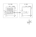
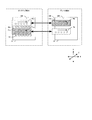
- FIG. 1 is a schematic diagram showing the configuration of the transfer device 1.
- the following description will be made with the left-right direction as the X direction, the direction from the near side to the far side as the Y direction, and the up and down direction as the Z direction.
- the transfer device 1 includes a pickup unit 10, a place unit 20, a transfer head 30, and a control unit 40.
- the pickup unit 10 and the place unit 20 are spaced apart from each other in the X direction.
- the pickup unit 10 is a unit that picks up the chip 100 from the adhesive sheet 200 on which the chip 100 is held in the transfer device 1.
- the pickup unit 10 includes a pickup table 11, a pickup table actuator 12, a pickup hammer 13, an upper disk cam 14, a pickup motor 15, a push-up needle 16, a lower disk cam 17, a push-up motor 18 and a camera 19. .
- one pickup position Pu for picking up the chip 100 held on the adhesive sheet 200 by the transfer head 30 is set.
- the pickup position Pu is intended to indicate a predetermined position in the X direction and the Y direction in the pickup unit 10.
- the pickup table 11 is a member having a flat surface that can hold the adhesive sheet 200 on which the chip 100 is held.
- the pickup table 11 holds the peripheral edge of the pressure-sensitive adhesive sheet 200 and extends the elastic pressure-sensitive adhesive sheet 200 to separate the chips 100 held on the pressure-sensitive adhesive sheet 200 from each other by a predetermined distance.
- the pickup stand actuator 12 is a unit composed of a plurality of actuators that can move the pickup stand 11 in a plane where the chip 100 is held (in other words, in the XY plane) and can rotate the pickup stand 11 in the plane. It is.
- the pickup stand actuator 12 moves the pickup stand 11 in accordance with a control signal supplied from the control unit 40, thereby transferring the desired chip 100 held on the adhesive sheet 200 to the pickup position Pu.
- the pickup hammer 13 has a bearing-like end portion disposed above the adhesive sheet 200 at the pickup position Pu.
- the bearing-like end of the pickup hammer 13 is connected to the upper disc cam 14 via an arm.
- the upper disk cam 14 is a disk-shaped cam that can rotate according to the rotation of the pickup motor 15.
- the pickup motor 15 rotates according to a control signal supplied from the control unit 40 and rotates the upper disk cam 14.
- the pick-up hammer 13 reciprocates in the Z direction when the arm moves in accordance with the rotation of the upper disc cam 14 and the bearing-like end portion moves in the Z direction.
- the push-up needle 16 has a needle-like configuration disposed below the adhesive sheet 200 at the pickup position Pu.
- the push-up needle 16 is connected to the lower disk cam 17 via an arm, and moves in the Z direction as the lower disk cam 17 rotates. As the push-up needle 16 moves upward in the Z direction by the rotation of the lower disc cam 17, the upper end of the push-up needle 16 contacts the adhesive sheet 200.
- the push-up needle 16 penetrates the adhesive sheet 200 at the upper end of the movement range, contacts the chip 100, and pushes up the chip 100.
- the push-up needle 16 is arranged in such a manner that the tip 100 having a needle-like upper end held at the pickup position Pu can be pushed up.
- the push-up motor 18 rotates the lower disk cam 17 in accordance with a control signal supplied from the control unit 40.
- the camera 19 is configured and arranged so that the chip 100 whose position is adjusted to the pickup position Pu on the adhesive sheet 200 and the chip 100 held in the periphery can be accommodated in the imaging range.
- the image of the chip 100 captured by the camera 19 is transmitted to the control unit 40.
- the place unit 20 is a part in the pickup unit 10 where the chip 100 adsorbed by the adsorption nozzle 31 is arranged on the arrangement sheet 300.
- the place unit 21, the place table actuator 22, the place hammer 23, the disc cam 24, the place A motor 25 and a camera 26 are provided.
- one place position Pl is set for placing the chip 100 sucked by the suction nozzle 31 held by the transfer head 30 on the placement sheet 300 (in other words, placing). .
- the place position pl is intended to indicate a predetermined position in the X direction and the Y direction in the place unit 20.
- the place position Pl is set at a position separated from the pickup position Pu by a predetermined distance in the X direction.
- the place table 21 is a member having a flat surface capable of holding the arrangement sheet 300 on which the chip 100 is arranged.
- seat 300 is a member on the sheet
- the place base actuator 22 is an actuator having a movable axis that can move the place base 21 in a plane direction (in other words, the X direction and the Y direction) on which the chip 100 is disposed (in other words, placed).
- a plurality of chips 100 held by the suction nozzle 31 of the transfer head 30 are arranged with a predetermined margin apart from each other.
- the position where each chip 100 on the arrangement sheet 300 is to be arranged will be referred to as a chip arrangement position.
- the chip placement positions are set in a matrix form including a plurality of columns and rows on the placement sheet 300.
- the place hammer 23 has a bearing-like end connected to an arm, and is connected to the disc cam 24 via the arm.
- the disc cam 24 is configured to be rotatable in accordance with the drive of the place motor 25. As the disk cam 24 rotates, the arm moves, so that the bearing-shaped end of the place hammer 23 reciprocates in the Z direction.
- the place motor 25 rotates the disc cam 24 in accordance with a control signal supplied from the control unit 40.
- the camera 26 is configured and arranged so that the chip 100 placed at the place position Pl on the arrangement sheet 300 and the periphery thereof can be accommodated in the imaging range.
- the image of the arrangement sheet 300 captured by the camera 26 is transmitted to the control unit 40.
- the transfer head 30 holds a plurality of cylindrical suction nozzles 31 and moves between the pickup unit 10 and the place unit 20 under the operation of the head actuator 32 to perform the pickup operation and place operation of the chip 100.
- the transfer head 30 is disposed above the pickup table 11 of the pickup unit 10 and the place table 21 of the place unit 20 in the Z direction.
- the suction nozzle 31 is connected to a decompression device (not shown) such as a vacuum pump via an intake passage (not shown) provided in the transfer head 30, and corresponds to a control signal supplied from the control unit 40. Then, suction of the chip 100 to be contacted and release of the suction are performed.
- a decompression device such as a vacuum pump
- an intake passage not shown
- the head actuator 32 is a uniaxial actuator that can move the transfer head 30 in the X direction in accordance with a control signal supplied from the control unit 40.
- the head actuator 32 moves the transfer head 30 between the pickup unit 10 and the place unit 20 along a straight line connecting the pickup position Pu and the place position Pl as indicated by an arrow in FIG.
- the transfer head 30 is provided with a spring mechanism that holds the lower end of the suction nozzle 31 at a predetermined distance from the upper end of the chip 100 in the Z direction and further biases the suction nozzle 31 upward in the Z direction so as to fix the suction nozzle 31 at the holding position.
- a spring mechanism that holds the lower end of the suction nozzle 31 at a predetermined distance from the upper end of the chip 100 in the Z direction and further biases the suction nozzle 31 upward in the Z direction so as to fix the suction nozzle 31 at the holding position.
- FIG. 2 is a diagram showing the arrangement and operation directions of the pickup table 11 of the pickup unit 10, the place table 21 of the place unit 20, and the transfer head 30 when the transfer device 1 of FIG. 1 is viewed from above in the Z direction. .
- the transfer head 30 has a plurality of suction nozzles 31 separated from each other by a predetermined margin on a straight line connecting the pickup position Pu of the pickup unit 10 and the place position Pl of the place unit 20. Hold in a row. Accordingly, in the pickup unit 10, when the transfer head 30 is moved in the X direction by the operation of the head actuator 32, the suction nozzles 31 held by the transfer head 30 are transferred to the pickup position Pu one by one. The On the other hand, in the place unit 20, the transfer head 30 is moved in the X direction by the operation of the head actuator 32, so that the suction nozzles 31 held by the transfer head 30 are transferred to the place position Pl one by one. Is done.
- the control unit 40 is a control CPU that controls the operation of each unit of the pickup unit 10, the place unit 20, and the transfer head 30, and is electrically connected to each unit and operates by supplying a control signal. Take control.
- the control unit 40 sets position coordinates for each chip 100 by analyzing an image of the chip 100 on the adhesive sheet 200 transmitted from the camera 19, for example.
- the control unit 40 adjusts the position of the pickup table 11 so that the chip 100 comes to the pickup position Pu by operating the pickup table actuator 12 according to the desired chip 100 position coordinates.
- control unit 40 sets the position coordinates on the placement sheet 300, operates the place base actuator 22 so that the desired position is the chip placement position, and the chip placement position comes to the place position Pl. Adjust the position.
- control unit 40 performs quality inspection, position information acquisition, and the like of the chip 100 arranged on the arrangement sheet 300 based on the image analysis result transmitted from the camera 26.
- FIG. 3 shows the positional relationship of each part separately from state 1 to state 4.
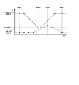
- FIG. 4 shows time-series changes in the Z direction of the lower end of the pickup hammer 13 and the upper end of the push-up needle 16. It is a graph to show. The operation of each unit described below is performed under the control of the control unit 40.
- the pick-up table actuator 12 moves the pick-up table 11, and the desired chip 100 is moved to the pick-up position Pu (on the axis indicated by the dashed line).
- the head actuator 32 moves the transfer head 30 and moves the desired suction nozzle 31 to the pickup position Pu (state 1).
- the lower end of the pickup hammer 13 and the upper end of the push-up needle 16 are in their initial positions as shown in FIG.
- the pickup motor 15 rotates the upper disk cam 14 and moves the pickup hammer 13 downward.
- the pickup hammer 13 contacts the upper end of the suction nozzle 31 and then pushes down the suction nozzle 31 against the biasing force of the spring mechanism that biases the suction nozzle 31 upward.
- the suction nozzle 31 pushed down contacts the chip 100 at a position where the pickup hammer 13 reaches the lower end of the moving range, and sucks the chip 100.
- the push-up motor 18 rotates the lower disk cam 17 and moves the push-up needle 16 toward the tip 100 (state 2).
- the pickup motor 15 rotates the upper disk cam 14 and moves the pickup hammer 13 upward to release the suction nozzle 31 from being pushed down.
- the suction nozzle 31 released from being pushed down moves upward in a state where the chip 100 is sucked by the biasing force of the spring mechanism.
- the upper end of the push-up needle 16 penetrates the adhesive sheet 200 and pushes the chip 100 upward, and moves the lower end of the chip 100 in the direction of peeling from the adhesive sheet 200 (state 3).
- the pick-up hammer 13 and the push-up needle 16 are returned to their initial positions as shown in FIG. 4, and the suction nozzle 31 having the tip 100 sucked to the lower end is also returned to the initial position in the Z direction.
- the pickup table actuator 12 moves the pickup table 11 and moves the next chip 100 to the pickup position Pu.
- the head actuator 32 moves the transfer head 30 and moves the next suction nozzle 31 to the pickup position Pu (state 4).
- the chip 100 is sucked by the suction nozzle 31 of the transfer head 30 by the operation described above. By repeating the above-described operation a plurality of times, the chip 100 is sucked by each of the plurality of suction nozzles 31 held by the transfer head 30.
- the place operation in the place unit 20 is performed in the same procedure. A specific procedure will be described below.
- the place table actuator 22 moves the place table 21, and moves the desired chip arrangement position on the arrangement sheet 300 to the place position Pl.
- the head actuator 32 moves the transfer head 30 and moves the suction nozzle 31 that sucks the chip 100 to the place position Pl.
- the place hammer 23 is in the initial position.
- the place motor 25 rotates the disc cam 24 and moves the place hammer 23 downward.
- the place hammer 23 contacts the upper end of the suction nozzle 31 and then pushes the suction nozzle 31 downward against the biasing force of the spring mechanism that biases the suction nozzle 31 upward.
- the chip 100 sucked by the sucked suction nozzle 31 comes into contact with the arrangement sheet 300 at a position where the place hammer 23 reaches the lower end of the moving range.
- the control unit 40 releases the suction of the suction nozzle 31 that holds the chip 100, whereby the chip 100 is placed at the chip placement position on the placement sheet 300. Since the arrangement sheet 300 has adhesiveness, the chip 100 adheres to the arrangement sheet 300 at the chip arrangement position.
- the place motor 25 rotates the disc cam 24 and moves the place hammer 23 upward to release the suction nozzle 31 from being pushed down.
- the suction nozzle 31 released from being pushed down is moved upward in a state where the chip 100 is not sucked by the biasing force of the spring mechanism.
- the place base actuator 22 moves the place base 21 to place the next chip at the place position Pl. Move position.
- the head actuator 32 moves the transfer head 30 and moves the suction nozzle 31 that sucks the next chip 100 to the place position Pl.
- the chip 100 transferred by the transfer head 30 is arranged on the arrangement sheet 300 by the operation described above.
- the chips 100 respectively adsorbed by the plurality of adsorption nozzles 31 held by the transfer head 30 are arranged on the arrangement sheet 300.
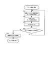
- FIG. 5 is a flowchart showing the overall operation flow including the pick-up operation and the place operation by the transfer device 1.
- the adhesive sheet 200 on which the chip 100 is held is placed on the pickup table 11 of the pickup unit 10 (step S1).
- the arrangement sheet 300 on which the chip 100 is moved is installed on the place table 21 of the place unit 20 (step S2).
- the camera 19 of the pickup unit 10 captures images of all the chips 100 held on the adhesive sheet 200 and transmits the image information to the control unit 40. Based on the transmitted image information, the control unit 40 sets coordinates for each chip 100 on the adhesive sheet 200 and generates position information (step S3). The generated position information is stored in a memory in the control unit 40.
- control unit 40 moves the transfer head 30 to the pickup unit 10 (step S4) and executes a pickup operation (step S5).
- the chip 100 held on the adhesive sheet 200 is adsorbed by each of the plurality of adsorption nozzles 31 in the transfer head 30.
- the pickup operation will be described in detail later.
- control unit 40 moves the transfer head 30 to the place unit 20 (step S6) and executes a place operation (step S7).
- a place operation the chip 100 sucked by each of the plurality of suction nozzles 31 in the transfer head 30 is placed on the placement sheet 300.
- the place operation will be described in detail later.
- the controller 40 repeats a series of operations from step S4 to step S7 until all the chips 100 to be moved on the adhesive sheet 200 are moved to the arrangement sheet 300 (step S8: Yes), End the operation.
- control unit 40 sets the chip 100 to be picked up first as a reference chip.
- the camera 19 captures an image of the reference chip and transmits image information to the control unit 40. Based on the transmitted image information, the control unit 40 sets coordinates again on the reference chip and generates position information (step S101).
- the control unit 40 compares the position information of all the chips 100 acquired first (FIG. 5, step S3) with the position information of the reference chips newly acquired, and the position of the reference chip is the first (that is, step S3).
- the amount of deviation from the position (detected in S3) is detected, and a position correction amount for correcting the deviation is calculated (step S102).
- the control unit 40 applies the reference chip position information acquired anew, and updates the stored reference chip position information (step S103).
- control unit 40 operates the pickup table actuator 12 based on the updated position information of the reference chip, and moves the pickup table 11 so that the reference chip is moved to the pickup position Pu (step S104).
- control unit 40 operates the head actuator 32 to move the transfer head 30 so that the suction nozzle 31 that does not suck the chip 100 is moved to the pickup position Pu (step S105). ).
- the control unit 40 causes the suction nozzle 31 to suck the reference chip and picks up the chip 100 (step S106). Specifically, the control unit 40 drives the pickup motor 15 to cause the pickup hammer 13 to push down the suction nozzle 31. At the same time, the control unit 40 drives the push-up motor 18 to push the tip 100 up by the push-up needle 16. The chip 100 is adsorbed by contact with the suction nozzle 31 pushed down by the pickup hammer 13, and further, the suction nozzle 31 moves upward and is pushed up by the push-up needle 16, so that the chip 100 is peeled off from the adhesive sheet 200 and picked up. Is done.
- step S107: Yes when there is a chip 100 that can be picked up (step S107: Yes) and there is a suction nozzle 31 that can suck the chip 100 without suction (step S108: Yes), the next chip 100 is picked up. Is done.
- the control unit 40 reads the position information stored for the next chip 100, compares the coordinates of the chip 100 with the coordinates of the reference chip before update (that is, the coordinates detected in step S3), and the chip It is determined whether the position 100 is within the correction amount application area.
- the correction amount application area is intended to indicate a predetermined range starting from the position coordinates of the reference chip. Within such a correction amount application area, for each chip 100, between the detection of the first chip 100 position (ie, step S3 in FIG. 5) and the re-detection of the position of the reference chip (ie, step S101 in FIG. 6). It can be considered that the positional deviations generated in the same are the same.
- the displacement of the position of the chip 100 is a major factor due to the expansion and contraction of the stretched adhesive sheet 200, and it is considered that the displacement of the position is the same if the chip 100 is within a certain range.
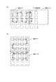
- Fig. 7 (a) shows the positional relationship between the reference chip and the correction amount application area. If the chip 100B to be picked up is present in the correction amount application area after the reference chip A has been picked up, the positional deviation of the chip 100B is considered to be the same as the positional deviation of the reference chip A. It is done. For this reason, it is considered that the position information after the shift of the chip 100B can be calculated by applying the correction amount of the reference chip A without detecting the coordinates again for the chip 100B and acquiring the position information.
- the predetermined range centering on the reference chip that defines the correction amount application area may be changed as appropriate.
- the predetermined range is appropriately determined according to the stretchability of the pressure-sensitive adhesive sheet 200 that causes the positional deviation of the chip 100. It may be changed.
- step S109 When the position of the next chip 100 is within the correction amount application area with the reference chip as a reference (step S109: Yes), the control unit 40 uses the position correction amount of the reference chip to calculate the position information of the chip 100. Correction is performed (step S110). Specifically, the corrected position information is obtained by applying the reference chip position correction amount to the stored position information of the chip 100.
- the control unit 40 Based on the corrected position information of the next chip 100, the control unit 40 operates the pickup table actuator 12 to move the pickup table 11 so that the chip 100 is moved to the pickup position Pu (step S111). . Subsequently, the next suction nozzle 31 that does not suck the chip 100 is moved to the pickup position Pu (step S105), and the next chip 100 is picked up.
- step S109 when the position of the next chip 100 is outside the correction amount application area based on the reference chip (step S109: No), the control unit 40 sets the chip 100 as a new reference chip. Then, for the new reference chip, the control unit 40 acquires position information by capturing an image (step S101), calculates a position correction amount (step S102), and updates the position information (step S103). Execute pickup operation.
- the case of picking up the chip 100C is illustrated in FIG. Since the chip 100C exists outside the correction amount application area with the reference chip A as a reference, the positional deviation of the chip 100C cannot be considered to be the same as the positional deviation of the reference chip A. Therefore, for the chip 100C, it is required to detect the coordinates again and acquire the position information. Therefore, as illustrated in FIG. 7B, the control unit 40 sets the chip 100C as a new reference chip and updates the position information. It can be considered that the positional deviation of the chip 100 existing in the correction amount application area based on the newly set reference chip C is the same as the positional deviation of the reference chip C.
- the control unit 40 performs the series of operations from step S105 to step S111 until there is no chip 100 that can be picked up (step S107: No), or there is an adsorbing suction nozzle 31 that does not adsorb the chip 100. The process is repeatedly executed until no more (step S108: No). When there is no chip 100 that can be picked up (step S107: No), or when there is no suckable suction nozzle 31 that does not suck the chip 100 (step S108: No), the control unit 40 performs the pick-up operation. End.
- the tact time can be greatly shortened as compared with the conventional apparatus in which the transfer is performed one by one.
- a pickup position Pu which is a position where the chip 100 is taken out is determined, and the suction nozzle 31 and the chip 100 are transferred to the pickup position pu one by one in order. For this reason, positioning can be performed in a relatively short time, and the tact time can be shortened. Note that the tact time can be further shortened by transferring the chip 100 and the suction nozzle 31 in parallel. Further, the chips 100 can be sorted by appropriately selecting the chip 100 to be adsorbed according to the state and shape of the chip 100.
- the control unit 40 operates the place table actuator 22 based on coordinates set in advance on the place table 21 so that the desired chip arrangement position on the arrangement sheet 300 is moved to the place position Pl. Is moved (step S201).
- control unit 40 operates the head actuator 32 to move the transfer head 30 so that the suction nozzle 31 sucking the chip 100 is moved to the place position Pl (step S202). ).
- the control unit 40 releases the suction so that the chip 100 sucked by the suction nozzle 31 is placed at the chip placement position on the placement sheet 300 (step S203). Specifically, the control unit 40 drives the motor 205 to cause the place hammer 23 to push down the suction nozzle 31. After the chip 100 adsorbed by the pressed suction nozzle 31 comes into contact with the placement sheet 300, the control unit 40 releases the suction of the suction nozzle 31 and places the chip 100 on the placement sheet 300.
- step S204 Until the next placeable chip 100 does not exist (step S204: No), the control unit 40 repeats a series of operations from step S201 to step S203.
- the control unit 40 takes an image of the chip 100 placed by the camera 26 and inputs image information. Receive. Based on the input image information, whether or not the chip 100 is arranged is inspected with respect to the arrangement accuracy of the chip 100 and the appearance of the chip 100 (step S208). After the chip 100 inspection, the control unit 40 ends the place operation.
- FIG. 9A is a diagram illustrating a chip arrangement position on the arrangement sheet 300 and an imaging area that is an area captured by the camera 26 by one imaging.
- the chip arrangement positions are arranged in a matrix at a predetermined distance in the XY directions.
- the imaging area of the camera 26 is a rectangular range including a plurality of chip arrangement positions, for example.
- the image pickup area of the camera 26 contains four chips 100 in the X direction and three in the Y direction, for a total of twelve chips 100.
- the transfer head 30 holds twelve suction nozzles 31.
- twelve chips 100 can be arranged on the arrangement sheet 300 by one pick-up operation and place operation.
- the chips 100 are arranged as indicated by the arrows in FIG. 9B, six chips 100 are arranged in the X direction and two chips 100 are arranged in the Y direction.
- the next chip arrangement position is adjacent to the previous chip arrangement position (in other words, because it is the shortest distance)
- the arrangement from the arrangement of one chip 100 to the arrangement of the next chip 100 is performed.
- the amount of movement of the sheet 300 (in other words, the amount of movement of the place table 21) is the smallest. For this reason, the time required for the movement of the arrangement sheet 300 is minimized, which is beneficial for shortening the tact time.
- the twelve chips 100 that are arranged do not fit within the imaging area of the camera 26.
- the camera 26 is required to move the arrangement sheet 300 and capture images in the imaging area 1 and the imaging area 2 as shown in FIG. 9B.
- the tact time is extended and the amount of processing for moving the arrangement sheet 300 is increased, which is not preferable in terms of apparatus operation.
- the control unit 40 determines the arrangement method of the chips 100 so that all the chips 100 are accommodated in the imaging area. Specifically, as indicated by the arrows in FIG. 9C, all the twelve chips 100 are accommodated in the imaging area of the camera 26 in which four chips 100 in the X direction and three chips 100 are accommodated in the Y direction. The positions at which the chips 100 are arranged are determined in the zigzag order (in other words, to draw a rectangular wave).
- the chip 100 is arranged in the following manner. First, the arrangement of the chip 100 is started from one corner of the rectangular imaging area, and the chip 100 is arranged at a position separated by a predetermined distance along one side of the imaging area. After the chip 100 is disposed at the other corner of the imaging area, the chip 100 is disposed at a position separated by a predetermined distance along the side orthogonal to the above-described side. Subsequently, the chip 100 is arranged at a position parallel to the first side and separated by a predetermined distance in the opposite direction. When the chip arrangement position hits the side of the imaging area, the chip 100 is arranged at a position separated by a predetermined distance along the side. Subsequently, the chip 100 is arranged at a position separated by a predetermined distance in a direction parallel to the first side. By repeating the above, the chip 100 is arranged.
- the time required for the movement of the arrangement sheet 300 is reduced as described above, which is beneficial for shortening the tact time.
- the tact time for capturing an image is shortened.
- the control unit 40 determines the position at which the chips 100 are arranged in the zigzag manner described above so that all the chips 100 fit in the smallest possible imaging area.
- the place operation starts in the Y direction (in other words, the column direction), is arranged in a zigzag manner, and the imaging area is moved in the X direction (in other words, the row direction).
- the place operation is started in the X direction (row direction)
- the chips 100 are arranged in a zigzag manner
- the imaging area is set in the Y direction (column direction). It may be a mode of moving.
- FIG. 11 to 14 are schematic views showing the configuration of the transfer device 1 ′.
- FIG. 11 is a view of the transfer device 1 ′ as viewed from the Y direction.
- FIG. 12 shows the transfer device 1 ′ as viewed from above in the Z direction.
- FIG. 13 is a view of the pickup unit 10 ′ in the transfer device 1 ′ as viewed from the X direction
- FIG. 14 is a view of the place portion 20 ′ in the transfer device 1 ′ as viewed from the X direction.
- the transfer device 1 ′ includes a pickup unit 10 ′, a place unit 20 ′, and a control unit 40 ′, and a transfer head having the same configuration as the transfer head 30 included in the transfer device 1.
- 30a and a transfer head 30b The transfer head 30 a holds a plurality of suction nozzles 31 a having the same configuration as the suction nozzle 31, and the transfer head 30 b holds a plurality of suction nozzles 31 b having the same configuration as the suction nozzle 31.
- the transfer head 30a can be moved in the X direction by a head actuator 32a having the same configuration as the head actuator 32, and the transfer head 30b can be moved in the X direction by a head actuator 32b having the same configuration as the head actuator 32. Can be moved to.
- the transfer device 1 ′ includes two sets of the transfer head 30, the suction nozzle 31, and the head actuator 32.
- the transfer head 30a and the transfer head 30b are arranged at positions separated by a predetermined distance in the Y direction.
- the first pickup position Pua for the transfer head 30 a to suck the chip 100 and the second pickup position for the transfer head 30 b to suck the chip 100 Two kinds of pickup positions Pu with Pub are set.
- the place unit 20 ′ of the transfer apparatus 1 ′ the first place position Pla for the transfer head 30 a to place the chip 100 and the second place for the transfer head 30 b to place the chip 100 are used.
- Two place positions Pl with the other place positions Plb are set.
- the transfer head 30a holds the plurality of suction nozzles 31a in a line on the straight line connecting the pickup position Pua of the pickup unit 10 'and the place position Pla of the place unit 20', with a predetermined margin therebetween.
- the head actuator 32a included in the transfer head 30a includes the pickup unit 10 ′ and the place unit 20 as shown by the arrows in FIG. 12 along the straight line connecting the transfer head 30a to the pickup position Pua and the place position Pla. Move between '.
- the transfer head 30b holds the plurality of suction nozzles 31b in a line on the straight line connecting the pickup position Pub of the pickup section 10 'and the place position Plb of the place section 20' with a predetermined margin.
- the head actuator 32b included in the transfer head 30b includes the pickup unit 10 ′ and the place unit 20 as shown by the arrows in FIG. 12 along the straight line connecting the transfer head 30b to the pickup position Pub and the place position Plb. Move between '.
- the operation of the transfer head 30a and the transfer head 30b is controlled by the control unit 40 ′ so that one of them performs the pickup operation in the pickup unit 10 ′ while the other performs the place operation in the place unit 20 ′. .
- the pickup position Pua and the pickup position Pub of the pickup unit 10 ′ are set apart from each other by a predetermined distance in the Y direction, and the place position Pla and the place position Plb of the place unit 20 ′ are separated by the same distance in the Y direction. Is set. For this reason, the movement axis of the transfer head 30a and the movement axis of the transfer head 30b are parallel to each other.
- each part of the transfer device 1 ′ will be further described with reference to FIGS. 13 and 14.
- the pickup unit 10 ′ of the transfer apparatus 1 ′ holds the pickup hammer 13 a for pressing the suction nozzle 31 a held by the transfer head 30 a at the pickup position Pua, and the transfer head 30 b.
- Two pickup hammers including a pickup hammer 13b for pressing the suction nozzle 31b at the pickup position Pub are provided.
- the pick-up hammer 13a and the pick-up hammer 13b are connected to the upper disk cam 14 through the same arm so as to press the suction nozzle 31b at the corresponding pick-up position.
- the pickup hammer 13a and the pickup hammer 13b are simultaneously moved in the Z direction.
- the suction nozzle 31 held by either the transfer head 30a or the transfer head 30b during the pickup operation in the pickup unit 10 ' is pressed.
- the pickup unit 10 ′ of the transfer device 1 ′ includes a push-up needle 16, a disc cam 17 and a push-up motor 18 for pushing up the chip 100 (hereinafter referred to as a push-up needle unit). And a push-up needle actuator 50 that is movable in the Y direction.
- the push-up needle actuator 50 is an actuator that reciprocates the push-up needle 16 of the push-up needle unit between the pickup position Pua and the pickup position Pub under the control of the control unit 40 ′.
- the control unit 40 ′ causes the push-up needle actuator 50 to move the push-up needle unit to a position corresponding to the pick-up position Pua so that the push-up needle 16 pushes up the chip 100.
- the push-up needle actuator 50 moves the push-up needle unit to a position corresponding to the pickup position Pub, and the push-up needle 16 performs the push-up operation of the chip 100.
- the place unit 20 ′ of the transfer device 1 ′ holds the place hammer 23 a for pressing the suction nozzle 31 a held by the transfer head 30 a at the place position Pla, and the transfer head 30 b.
- Two place hammers including a place hammer 23b for pressing the suction nozzle 31b at the place position Plb are provided.
- the place hammer 23a and the place hammer 23b are connected to the disc cam 24 through the same arm so as to press the suction nozzle 31b at the corresponding place position. For this reason, when the disc cam 24 rotates according to the operation of the upper motor 25, the place hammer 23a and the place hammer 23b simultaneously move in the Z direction. According to the place hammer 23a and the place hammer 23b, the suction nozzle 31 held by either the transfer head 30a or the transfer head 30b during the place operation in the place portion 10 'is pressed.
- the adhesive sheet 200 that holds the chip 100 is placed on the pickup table 11 of the pickup unit 10 '(step S1).
- the arrangement sheet 300 on which the chip 100 is moved is placed on the place table 21 of the place unit 20 '(step S2).
- the camera 19 of the pickup unit 10 ′ captures images of all the chips 100 disposed on the adhesive sheet 200 and transmits image information to the control unit 40.
- the control unit 40 sets coordinates for each chip 100 on the adhesive sheet 200 and generates position information (step S3).
- the generated position information is stored in a memory in the control unit 40.
- control unit 40 moves the transfer head 30a to the pickup unit 10 '(step S4a) and executes a pickup operation (step S5a).
- control unit 40 moves the transfer head 30b to the place unit 20 '(step S4b) and executes a place operation (step S5b). Note that the first place operation at the start of the operation is not executed because the chip 100 is not held by the suction nozzle 31b of the transfer head 30b.
- control unit 40 moves the transfer head 30a to the place unit 20 '(step S6a) and executes a place operation (step S7a).
- control unit 40 moves the transfer head 30b to the pickup unit 10 '(step S6b), and executes a pickup operation (step S7b).
- the controller 40 repeats a series of operations from step S4 to step S7 until all the chips 100 to be moved on the adhesive sheet 200 are moved to the arrangement sheet 300 (step S8: Yes), End the operation.
- the transfer head 30 b can perform the place operation at the place portion 20 ′ while the transfer head 30 a is performing the pickup operation at the pickup portion 10 ′.
- the operation of the transfer head 30a does not affect the operation of the transfer head 30b and the operation of the transfer head 30b depends on the positional relationship and the movement path of the transfer head 30a and the transfer head 30b. It does not affect the operation of 30a.
- the transfer head 30a and the transfer head 30b can be operated in parallel, and in addition to the effect of the operation of the transfer apparatus 1, the tact time can be further shortened.
Landscapes
- Container, Conveyance, Adherence, Positioning, Of Wafer (AREA)
- Die Bonding (AREA)
Abstract
Description
本発明の部品移送装置の実施例である移送装置1の構成を図を参照しながら説明する。
移送装置1によるピックアップ動作及びプレース動作を含む、全体的な動作の流れを示すフローチャートである図5を参照して移送装置1の動作を説明する。
移送装置1のピックアップ部10によるチップ100のピックアップ動作について、図6のフローチャートを参照して説明する。
移送装置1のプレース部20によるチップ100のプレース動作について、図8のフローチャートを参照して説明する。
移送装置1の変形例である移送装置1’の構成を図11乃至図14を参照して説明する。
制御部40’は、ピックアップ位置Puaにおけるピックアップ動作時には、突き上げ針アクチュエータ50により突き上げ針ユニットをピックアップ位置Puaに対応する位置に移動させ、突き上げ針16によるチップ100の突き上げ動作を行わせる。他方で、ピックアップ位置Pubにおけるピックアップ動作時には、突き上げ針アクチュエータ50により突き上げ針ユニットをピックアップ位置Pubに対応する位置に移動させ、突き上げ針16によるチップ100の突き上げ動作を行わせる。
10 ピックアップ部、
11 ピックアップ台、
12 ピックアップ台アクチュエータ、
13 ピックアップハンマ、
14 円板カム、
15 ピックアップモータ、
16 突き上げ針、
17 下円板カム、
18 突き上げモータ、
19 カメラ(ピックアップ部)、
20 プレース部、
21 プレース台、
22 プレース台アクチュエータ、
23 プレースハンマ、
24 円板カム、
25 プレースモータ、
26 カメラ(プレース部)、
30 移載ヘッド、
31 吸着ノズル、
32 ヘッドアクチュエータ、
40 制御部、
100 チップ、
200 粘着シート、
300 配置シート。
Claims (4)
- ウエハ状態のチップを配置部へ配置する部品移送装置であって、
前記チップを配置するための配置部と、
前記チップを吸着する複数の吸着ノズルと、
前記配置部上において、前記チップを配置するためのプレース位置を決定する決定手段と、
前記配置部における前記プレース位置に前記複数の吸着ノズルを一つ一つ順番に位置決めする位置決め手段と、
前記複数の吸着ノズルのうちの一に吸着される前記チップを前記配置部上の前記プレース位置に配置するプレース手段と、
前記配置部上の撮像範囲内に配置される前記チップを撮像する撮像手段と
を備え、
前記決定手段は、前記プレース位置を、前記配置部における前記撮像範囲に含まれ、且つ夫々所定の距離離隔する複数の列及び複数の行から成るマトリックスの配置となるように決定し、
前記位置決め手段は、前記マトリックスの角部を含む列に含まれる全ての前記プレース位置に前記チップが配置された後に、順次隣接する列に含まれる全ての前記プレース位置に前記チップが配置されるように位置決めを行う、又は、前記マトリックスの角部を含む行に含まれる全ての前記プレース位置に前記チップが配置された後に、順次隣接する行に含まれる全ての前記プレース位置に前記チップが配置されるように位置決めを行うことを特徴とする部品移載装置。 - 前記位置決め手段は、前記プレース位置のうち一の前記プレース位置に前記チップが配置された後に、順次隣接する前記プレース位置に前記チップが配置されるように位置決めを行うことを特徴とする請求項1に記載の部品移載装置。
- 前記配置部上の前記撮像範囲内に配置される前記チップの位置情報を取得する取得手段を更に備えることを特徴とする請求項1に記載の部品移送装置。
- ウエハ状態のチップを配置部へ配置する部品移送装置における部品移送方法であって、
前記配置部上において、前記チップを配置するためのプレース位置を決定する決定工程と、
前記配置部における前記プレース位置に前記チップを保持する複数の吸着ノズルを一つ一つ順番に位置決めする位置決め工程と、
前記複数の吸着ノズルのうちの一に吸着される前記チップを前記配置部上の前記プレース位置に配置するプレース工程と、
前記配置部上の撮像範囲内に配置される前記チップを撮像する撮像工程と
を備え、
前記決定工程は、前記プレース位置を、前記配置部上に前記プレース位置を、夫々所定の距離離隔する複数の列及び複数の行から成るマトリックスとして決定し、
前記位置決め工程は、前記マトリックスの角部を含む列に含まれる全ての前記プレース位置に前記チップが配置された後に、順次隣接する列に含まれる全ての前記プレース位置に前記チップが配置されるように位置決めを行う、又は、前記マトリックスの角部を含む行に含まれる全ての前記プレース位置に前記チップが配置された後に、順次隣接する行に含まれる全ての前記プレース位置に前記チップが配置されるように位置決めを行うことを特徴とする部品移載方法。
Priority Applications (3)
| Application Number | Priority Date | Filing Date | Title |
|---|---|---|---|
| CN2010800661235A CN102834909A (zh) | 2010-04-13 | 2010-04-13 | 元件移送装置及方法 |
| PCT/JP2010/056616 WO2011128982A1 (ja) | 2010-04-13 | 2010-04-13 | 部品移送装置及び方法 |
| JP2011527086A JP4919241B2 (ja) | 2010-04-13 | 2010-04-13 | 部品移送装置及び方法 |
Applications Claiming Priority (1)
| Application Number | Priority Date | Filing Date | Title |
|---|---|---|---|
| PCT/JP2010/056616 WO2011128982A1 (ja) | 2010-04-13 | 2010-04-13 | 部品移送装置及び方法 |
Publications (1)
| Publication Number | Publication Date |
|---|---|
| WO2011128982A1 true WO2011128982A1 (ja) | 2011-10-20 |
Family
ID=44798375
Family Applications (1)
| Application Number | Title | Priority Date | Filing Date |
|---|---|---|---|
| PCT/JP2010/056616 Ceased WO2011128982A1 (ja) | 2010-04-13 | 2010-04-13 | 部品移送装置及び方法 |
Country Status (3)
| Country | Link |
|---|---|
| JP (1) | JP4919241B2 (ja) |
| CN (1) | CN102834909A (ja) |
| WO (1) | WO2011128982A1 (ja) |
Cited By (4)
| Publication number | Priority date | Publication date | Assignee | Title |
|---|---|---|---|---|
| JP2014036060A (ja) * | 2012-08-07 | 2014-02-24 | Sharp Corp | 半導体装置の製造方法及び半導体装置の製造装置 |
| JP2014096524A (ja) * | 2012-11-12 | 2014-05-22 | Canon Machinery Inc | ピックアップ方法およびピックアップ装置 |
| EP2938176A4 (en) * | 2012-12-20 | 2015-12-02 | Fuji Machine Mfg | CHIP SUPPLY DEVICE |
| KR20180111513A (ko) * | 2017-03-31 | 2018-10-11 | 토와 가부시기가이샤 | 절단 장치, 반도체 패키지의 부착 방법 및 전자 부품의 제조 방법 |
Citations (2)
| Publication number | Priority date | Publication date | Assignee | Title |
|---|---|---|---|---|
| JPH08330390A (ja) * | 1995-05-31 | 1996-12-13 | Nichiden Mach Ltd | ピックアップ装置及びピックアップ方法 |
| JP2009059961A (ja) * | 2007-08-31 | 2009-03-19 | Toshiba Components Co Ltd | ダイボンダー装置 |
Family Cites Families (3)
| Publication number | Priority date | Publication date | Assignee | Title |
|---|---|---|---|---|
| JP3719182B2 (ja) * | 2001-09-28 | 2005-11-24 | 松下電器産業株式会社 | 電子部品実装装置および電子部品実装方法 |
| JP3999170B2 (ja) * | 2003-07-08 | 2007-10-31 | シャープ株式会社 | 半導体チップのピックアップ方法及びピックアップ装置 |
| JP2010040738A (ja) * | 2008-08-05 | 2010-02-18 | Toshiba Corp | 半導体装置の製造装置及び製造方法 |
-
2010
- 2010-04-13 JP JP2011527086A patent/JP4919241B2/ja not_active Expired - Fee Related
- 2010-04-13 WO PCT/JP2010/056616 patent/WO2011128982A1/ja not_active Ceased
- 2010-04-13 CN CN2010800661235A patent/CN102834909A/zh active Pending
Patent Citations (2)
| Publication number | Priority date | Publication date | Assignee | Title |
|---|---|---|---|---|
| JPH08330390A (ja) * | 1995-05-31 | 1996-12-13 | Nichiden Mach Ltd | ピックアップ装置及びピックアップ方法 |
| JP2009059961A (ja) * | 2007-08-31 | 2009-03-19 | Toshiba Components Co Ltd | ダイボンダー装置 |
Cited By (6)
| Publication number | Priority date | Publication date | Assignee | Title |
|---|---|---|---|---|
| JP2014036060A (ja) * | 2012-08-07 | 2014-02-24 | Sharp Corp | 半導体装置の製造方法及び半導体装置の製造装置 |
| JP2014096524A (ja) * | 2012-11-12 | 2014-05-22 | Canon Machinery Inc | ピックアップ方法およびピックアップ装置 |
| EP2938176A4 (en) * | 2012-12-20 | 2015-12-02 | Fuji Machine Mfg | CHIP SUPPLY DEVICE |
| KR20180111513A (ko) * | 2017-03-31 | 2018-10-11 | 토와 가부시기가이샤 | 절단 장치, 반도체 패키지의 부착 방법 및 전자 부품의 제조 방법 |
| JP2018174191A (ja) * | 2017-03-31 | 2018-11-08 | Towa株式会社 | 切断装置、半導体パッケージの貼付方法及び電子部品の製造方法 |
| KR102158024B1 (ko) * | 2017-03-31 | 2020-09-21 | 토와 가부시기가이샤 | 절단 장치, 반도체 패키지의 부착 방법 및 전자 부품의 제조 방법 |
Also Published As
| Publication number | Publication date |
|---|---|
| CN102834909A (zh) | 2012-12-19 |
| JPWO2011128982A1 (ja) | 2013-07-11 |
| JP4919241B2 (ja) | 2012-04-18 |
Similar Documents
| Publication | Publication Date | Title |
|---|---|---|
| JP4919240B2 (ja) | 部品移送装置及び方法 | |
| JP4870857B2 (ja) | 部品移送装置及び方法 | |
| JP5789681B2 (ja) | 電子部品実装装置および電子部品実装方法 | |
| KR102044085B1 (ko) | 기판 보지 방법, 기판 보지 장치, 처리 방법 및 처리 장치 | |
| CN108364880B (zh) | 半导体制造装置及半导体器件的制造方法 | |
| JP3719182B2 (ja) | 電子部品実装装置および電子部品実装方法 | |
| JP7408455B2 (ja) | ダイボンディング装置および半導体装置の製造方法 | |
| TW200428539A (en) | Apparatus and method for picking up semiconductor chip | |
| CN111656504A (zh) | 裸片拾取方法及装置 | |
| JP5745104B2 (ja) | 電子部品移送装置および電子部品移送方法 | |
| JP4919241B2 (ja) | 部品移送装置及び方法 | |
| JP5789680B2 (ja) | 電子部品実装装置および電子部品実装方法 | |
| CN111739818B (zh) | 半导体制造装置以及半导体器件的制造方法 | |
| JP2012134510A (ja) | 部品移送装置及び方法 | |
| JP2022152575A (ja) | 実装ツールおよび実装装置 | |
| JP4184592B2 (ja) | 導電性ボールの吸引配列方法及び吸引配列装置 | |
| JP5537801B2 (ja) | 位置決め装置、位置決め方法、およびボンディング装置 | |
| JP4457715B2 (ja) | チップのピックアップ装置およびピックアップ方法 | |
| JP7486264B2 (ja) | ピックアップ方法、及び、ピックアップ装置 | |
| JP2006190863A (ja) | 部品搭載装置および部品搭載方法ならびに部品反転装置および部品反転方法 | |
| JP2022180237A (ja) | 部品圧着装置および部品圧着方法 | |
| JP2014096524A (ja) | ピックアップ方法およびピックアップ装置 | |
| JP2010109040A (ja) | チップ実装装置およびチップ実装方法 |
Legal Events
| Date | Code | Title | Description |
|---|---|---|---|
| WWE | Wipo information: entry into national phase |
Ref document number: 201080066123.5 Country of ref document: CN |
|
| WWE | Wipo information: entry into national phase |
Ref document number: 2011527086 Country of ref document: JP |
|
| 121 | Ep: the epo has been informed by wipo that ep was designated in this application |
Ref document number: 10849820 Country of ref document: EP Kind code of ref document: A1 |
|
| NENP | Non-entry into the national phase |
Ref country code: DE |
|
| 122 | Ep: pct application non-entry in european phase |
Ref document number: 10849820 Country of ref document: EP Kind code of ref document: A1 |