WO2011125340A1 - 二輪車のシートカバー装置 - Google Patents
二輪車のシートカバー装置 Download PDFInfo
- Publication number
- WO2011125340A1 WO2011125340A1 PCT/JP2011/002105 JP2011002105W WO2011125340A1 WO 2011125340 A1 WO2011125340 A1 WO 2011125340A1 JP 2011002105 W JP2011002105 W JP 2011002105W WO 2011125340 A1 WO2011125340 A1 WO 2011125340A1
- Authority
- WO
- WIPO (PCT)
- Prior art keywords
- seat cover
- casing
- handle
- seat
- shaft
- Prior art date
- Legal status (The legal status is an assumption and is not a legal conclusion. Google has not performed a legal analysis and makes no representation as to the accuracy of the status listed.)
- Ceased
Links
Images




Classifications
-
- B—PERFORMING OPERATIONS; TRANSPORTING
- B62—LAND VEHICLES FOR TRAVELLING OTHERWISE THAN ON RAILS
- B62J—CYCLE SADDLES OR SEATS; AUXILIARY DEVICES OR ACCESSORIES SPECIALLY ADAPTED TO CYCLES AND NOT OTHERWISE PROVIDED FOR, e.g. ARTICLE CARRIERS OR CYCLE PROTECTORS
- B62J1/00—Saddles or other seats for cycles; Arrangement thereof; Component parts
- B62J1/18—Covers for saddles or other seats; Paddings
- B62J1/20—Detachable covers; Detachable pads
-
- B—PERFORMING OPERATIONS; TRANSPORTING
- B62—LAND VEHICLES FOR TRAVELLING OTHERWISE THAN ON RAILS
- B62J—CYCLE SADDLES OR SEATS; AUXILIARY DEVICES OR ACCESSORIES SPECIALLY ADAPTED TO CYCLES AND NOT OTHERWISE PROVIDED FOR, e.g. ARTICLE CARRIERS OR CYCLE PROTECTORS
- B62J19/00—Parking covers for cycles
-
- B—PERFORMING OPERATIONS; TRANSPORTING
- B62—LAND VEHICLES FOR TRAVELLING OTHERWISE THAN ON RAILS
- B62K—CYCLES; CYCLE FRAMES; CYCLE STEERING DEVICES; RIDER-OPERATED TERMINAL CONTROLS SPECIALLY ADAPTED FOR CYCLES; CYCLE AXLE SUSPENSIONS; CYCLE SIDECARS, FORECARS, OR THE LIKE
- B62K2202/00—Motorised scooters
Definitions
- the present invention relates to a seat cover device that houses a belt-like seat cover that covers a seat of a motorcycle.
- a seat cover device that houses the seat cover is provided in the vehicle body, and the seat cover is pulled out from the seat cover device in a timely manner to cover the seat.
- the seat cover device includes a case attached to a vehicle body, a winding shaft rotatably supported in the case, a seat cover having one end coupled to the winding shaft and wound around the winding shaft, and a seat cover wound And a spring for rotating and energizing the winding shaft in the direction.
- the seat cover is pulled out through a slot formed in the case, and the upper surface of the seat is covered with the seat cover.
- the seat cover is provided with a locking member at the tip thereof, and is maintained in a state of covering the seat by fixing the locking member at an appropriate position of the vehicle body.
- the seat cover device when the seat cover is stored, the seat cover is wound around the take-up shaft by the urging force of the spring and pulled into the case.
- the locking member provided at the front end of the seat cover is in contact with the peripheral edge of the slot by the biasing force of the spring.
- the locking member does not have means for restricting relative movement in the direction orthogonal to the slot penetration direction with respect to the case. For this reason, the locking member moves relative to the case due to vibrations applied to the vehicle body during traveling of the motorcycle and impacts applied to the vehicle body when overcoming obstacles on the road surface, and vibration and collision sounds (sounding sounds). There was a problem that caused. Further, since the locking member moves with respect to the case, there is a problem in that the locking member cannot be maintained at a position where the user can easily hold it during use.
- the present invention has been made in view of the above problems, and in the seat cover device, the terminal portion of the seat cover in the housed state (unused state) is maintained at a certain position and posture with respect to the casing.
- the object is to prevent vibration noise and make it easier for the user to pull out the seat cover.
- the present invention provides a seat cover device (20) that houses a belt-like seat cover (27) that covers a seat (12) of a motorcycle (10), through which the seat cover can pass.
- a handle having a rod-like connecting portion (81) to which the other end portion of the seat cover that has passed through the slot is coupled, and a gripping portion (82) that curves and extends so as to connect both ends of the connecting portion ( 30) and an urging means (26) provided between the casing and the take-up shaft for urging the take-up shaft in a rotational direction for taking up the seat cover.
- the handle includes a fitting hole (46) in each of the lateral portions of both ends in the longitudinal direction of the slot, and the handle includes a convex portion (83) in each of the both ends of the grip portion.
- the fitting hole is formed in a shape having an inclined surface (47) so as to become wider toward the opening end side, and the convex portion is complementary to the fitting hole. It has a unique shape.
- the convex portion has an elastic claw (86) on a surface thereof, and the fitting hole is in a state in which the convex portion is fitted into the fitting hole. It has a locking hole (49) to be fitted.
- Another aspect of the present invention is characterized in that the casing is provided with a damper device (29) for damping the rotation of the winding shaft.
- Another aspect of the present invention is characterized in that the damper device is connected to the take-up shaft via a one-way clutch (28) and attenuates only the rotation of the take-up shaft in the direction of winding the seat cover.
- the casing is disposed at a lower portion of a seat of a scooter type motorcycle such that the grip portion protrudes forward with respect to the casing, and the scooter type motorcycle includes the seat.
- a standing handle (19) is provided at the rear of the seat, and the grip portion is hooked on the standing handle in a state where the seat cover covers the seat.
- the standing handle is used together as the locking means for fixing the handle, it is not necessary to separately provide the locking means on the vehicle body, and the number of parts can be reduced and the design can be improved.
- the handle can be disposed at a predetermined position and posture with respect to the casing in the seat cover retracted state, vibration vibration of the handle can be suppressed, and the user can hold the handle. Can be made easier.
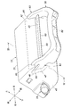
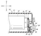
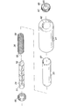
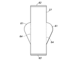
- FIG. 1 Perspective view of a scooter type motorcycle equipped with a seat cover device Perspective view of seat cover device Right side view of the seat cover device IV-IV sectional view of Fig. 2 VV cross section of Fig. 3 Exploded perspective view showing the main part of the seat cover device Development view showing the seat cover The perspective view which shows the use condition of a seat cover apparatus
- a vehicle 10 which is a scooter type motorcycle includes an operation handle 11, a seat 12 for a driver to sit on, and a low-floor foot provided between the operation handle 11 and the seat 12. And a platform 13.
- the lower side and the rear side of the seat 12 are covered with a rear cover 14.
- the rear cover 14 includes a wall portion 15 that extends in the vertical direction from the footrest 13 to the front end portion of the seat 12, and a tail portion 16 that extends substantially horizontally in the rear of the seat 12.
- An attachment hole 18 for attaching the seat cover device 20 is formed in the wall portion 15.
- the seat cover device 20 is inserted into the attachment hole 18 and attached to a vehicle body frame (not shown) existing inside the rear cover 14.
- the seat cover device 20 includes a casing 23 including a casing body 21 and a casing lid portion 22, a fixed shaft 24, a winding shaft 25, a coil spring 26, and a seat cover 27.
- the casing 23, the fixed shaft 24, the winding shaft 25, and the handle 30 are made of, for example, a resin material.
- the casing main body 21 is formed in a box shape extending in the left-right direction, and has an opening 41 on the rear side.
- the front side portion 42 of the casing body 21 is formed in an arcuate curved surface so that the middle portion in the vertical direction protrudes most forward.
- the front side portion 42 is formed with a slot 43 that is a through hole extending in the left-right direction.
- the opening 41 of the casing body 21 is closed by a casing lid 22 that engages with the casing body 21.
- a notch 39 is formed in a part of the lower portion of the opening 41. In a state where the casing main body 21 and the casing lid 22 are combined, the notch 39 functions as a discharge hole for discharging water accumulated in the casing 23 to the outside.
- a bottomed handle fitting hole 46 that opens to the outer surface of the front side portion 42 and is recessed rearward at each of the left side portion 44 and the boundary portion between the right side portion 45 and the front side portion 42 of the casing main body portion 21. 46 is formed.
- the handle fitting holes 46 are continuous to the outer surface of the left side portion 44 or the right side portion 45.
- Each handle fitting hole 46 includes an inclined surface portion 47 at the lower portion of the hole wall, and the width in the vertical direction increases as it advances forward.
- Each handle fitting hole 46 has a locking hole 49 formed in a hole wall portion 48 facing the left and right sides.
- the fixed shaft 24 is formed in a columnar shape, and a spring locking hole 51 for locking one end portion 55 of the coil spring is formed on the outer peripheral surface thereof. Further, at one end portion of the fixed shaft 24, a convex portion 52 is formed that fits in a non-rotatable manner in a hole 54 (see FIG. 5) formed in the inner surface of the right side portion 45 of the casing main body portion 21.
- the coil spring 26 is a torsion spring, and both end portions 55 and 56 thereof are bent to form a hook.
- the coil spring 26 is sheathed around the fixed shaft 24, and one end 55 is locked in the spring locking hole 51.
- the winding shaft 25 is a cylindrical body having both ends opened.
- a slit 57 that is continuous from one end to the other end is formed in the circumferential portion of the winding shaft 25.
- the sheet cover 27 is an impermeable sheet, and may be a resin material formed into a sheet (film) shape, or a water-repellent processed woven or non-woven fabric. As shown in FIG. 7, the seat cover 27 is formed in a band shape, and includes projecting portions 61 that project in the width direction on both sides of the intermediate portion in the longitudinal direction. The base end portion 62 of the seat cover 27 is bent back a plurality of times and is thicker than other portions. The handle 30 is coupled to the distal end portion 63 of the seat cover 27 after the seat cover 27 is accommodated in the casing 23.
- the seat cover 27 is coupled to the take-up shaft 25 by the base end portion 62 being engaged with the slit 57 of the take-up shaft 25.
- the seat cover 27 is wound around the take-up shaft 25 after the overhanging portion 61 is folded along the folding line 64 shown in FIG.
- the take-up shaft 25 is packaged around a fixed shaft 24 to which a coil spring 26 is attached.
- Cylindrical end caps 66 and 67 are fitted to both ends of the winding shaft 25 so as to rotate together with the winding shaft 25.
- a gear 68 is formed on the outer peripheral surface of one end cap 67 in the circumferential direction.
- the end cap 67 is formed with a spring locking hole 65 penetrating in the axial direction, and the other end 56 of the coil spring 26 is locked in the spring locking hole 65.
- the fixed shaft 24 is longer in the axial direction than the winding shaft 25 to which the end caps 66 and 67 are attached, and both ends protrude laterally from the end caps 66 and 67.
- the inner peripheral portions of both end caps 66 and 67 are rotatably supported at the end of the fixed shaft 24.
- the take-up shaft 25 is rotatably supported by the fixed shaft 24 via both end caps 66 and 67.
- the fixed shaft 24 and the winding shaft 25 are connected via a coil spring 26, and the fixed shaft 24 and the winding shaft 25 rotate relative to each other, whereby the fixed shaft 24 and the winding shaft 25 are coiled.
- the restoring force of the spring 26 is applied as an urging force.
- the fixed shaft 24 has a convex portion 52 fitted in a hole 54 formed on the inner surface of the right side portion 45 and the other end portion supported by a bearing portion (not shown) formed on the inner surface of the left side portion 44.
- the casing body 21 is supported so as not to rotate.
- the winding shaft 25 is rotatably supported by the casing main body 21 via the fixed shaft 24 and the end caps 66 and 67.
- the handle 30 includes a connecting portion 81 that is a rod-like member extending in the left-right direction, a U-shaped gripping portion 82 that extends so as to connect both ends of the connecting portion 81, and both ends of the gripping portion 82. And handle convex portions 83 and 83 projecting from the portion.
- the front end portion 63 of the seat cover 27 is folded back so as to wrap around the connecting portion 81, and is joined to itself by sewing or heat welding to form a loop.
- the distance between the handle convex portions 83 is substantially equal to the distance between the hole wall portions 48 facing the left and right sides of the handle fitting holes 46.
- Each handle convex portion 83 has a bifurcated tip to form a first convex portion 84 and a second convex portion 85.
- Each first convex portion 84 is formed in a shape complementary to the handle fitting hole 46 and is tapered.
- elastic claws 86 are formed in the portions of the two first convex portions 84 facing each other, with the claw portions protruding in directions close to each other.
- each handle convex portion 84 of each handle convex portion 83 corresponds to each handle fitting hole 46. Is fitted.
- the claw portion of each elastic claw 86 abuts the hole wall portion 48 facing the left and right sides of each handle fitting hole 46, and outwards to the left and right.
- the first protruding portion 84 enters each locking hole 49 by elastic force.
- the second convex portion 85 is disposed along the front side portion 42 of the casing main body portion 21 and is engaged with the peripheral edge of the handle fitting hole 46.
- the gripping part 82 stands up (projects) with respect to the front surface of the front side part 42.
- a one-way clutch 28 is rotatably supported inside the casing body 21.
- the one-way clutch 28 may be a known one having a first gear 92 and a second gear 93 arranged coaxially.
- the first gear has a shaft portion that protrudes in the rotation axis direction
- the second gear has a hole that receives the shaft portion, and extends in the circumferential direction between the shaft portion and the hole.
- a plurality of spaces are formed, and a ball and a spring for biasing the ball toward one side in the circumferential direction are provided in each space.
- the first gear 92 of the one-way clutch 28 meshes with the gear 68 of the end cap 67.
- the second gear 93 rotates together with the first gear 92, while the take-up shaft 25 rotates in the direction in which the seat cover 27 is sent out from the casing 23.
- the second gear 93 does not rotate.
- a through hole 94 is formed in the right side 45 of the casing body 21.
- a damper casing 96 of the rotary damper 29 is fitted in the through hole 94.
- the damper casing 96 is fixed to the right side 45 by screws.
- the damper casing 96 has an internal space filled with oil, and rotatably supports a rotating shaft (not shown) protruding from the internal space to the outside.
- the rotary shaft includes a plurality of vanes in a portion in the internal space, and a gear 98 in a portion outside the damper casing 96.
- the gear 98 meshes with the second gear 93 of the one-way clutch 28.
- the seat cover device 20 has a casing 23 inserted into the mounting hole 18 and is attached to the frame via a bracket (not shown).
- the front side portion 42 of the casing main body portion 21 constitutes a part of the wall surface of the wall portion 15, and the gripping portion 82 of the handle 30 protrudes forward from the wall surface of the wall portion 15.
- a standing handle 19 is attached to the tail portion 16 behind the seat 12.
- the standing handle 19 is formed in a V-shape, and is attached to the vehicle body frame existing at the inner side of the rear cover 14 at both ends so that an intermediate portion thereof protrudes toward the rear upper side.
- the method of using the seat cover device 20 described above and the function and effect will be described.
- the user grips the grip portion 82 of the handle 30 in a state where the vehicle 10 is erected (the state shown in FIG. 1), and pulls the seat cover 27 forward and upward against the urging force of the coil spring 26. .
- the damping action of the rotary damper 29 is not applied to the winding shaft 25.
- the both overhang portions 61 of the seat cover 27 are expanded.
- the handle 30 is moved to the rear side of the vehicle 10 and the seat 12 is covered with the seat cover 27.
- the two overhang portions 61 cover the side portions of the sheet 12.
- the gripping portion 82 of the handle 30 is locked to an intermediate portion protruding rearward of the standing handle 19.
- the excessively drawn portion of the seat cover 27 is drawn into the casing 23 by the urging force of the coil spring 26, and the seat cover 27 covers the surface of the seat 12 as shown in FIG. Maintained.
- the seat cover 27 When the seat cover 27 is stored in the casing 23 from the state in which the seat 12 is covered with the seat cover 27, the grip portion 82 of the handle 30 locked to the standing handle 19 is gripped, and the handle 30 and the standing handle 19 are held. And the handle 30 is moved to the front side of the seat 12. Accordingly, the seat cover 27 is wound around the winding shaft 25 that is rotationally driven by the urging force of the coil spring 26 and pulled into the casing 23. At this time, both the overhang portions 61 are folded along the folding line 64 so that the both overhang portions 61 can pass through the slot 43.
- the first protrusions 84 of the both handle protrusions 83 are fitted into the both handle fitting holes 46. Since the handle fitting hole 46 is wider in the vertical direction toward the opening end side (front end side), and the first convex portion 84 is tapered, the first convex portion 84 is the handle fitting hole. The first convex portion 84 is guided by the inclined surface portion 47 of the handle fitting hole 46 and moves to a predetermined fitting position. In a state where the first convex portion 84 is fitted in the handle fitting hole 46, the elastic claw 86 is locked in the locking hole 49. When the handle 30 approaches the casing 23, the user may release the handle 30 and fit the first convex portion 84 into the handle fitting hole 46 by the urging force of the coil spring 26.
- the first convex portion 84 of the handle 30 is fitted into the handle fitting hole 46 of the casing 23 in a state where the seat cover 27 is accommodated in the casing 23, and the handle 30. Since the grip portion 82 is maintained in an upright (projecting) posture with respect to the front side portion 42 of the casing 23, the user can easily grip the grip portion 82.
- the first convex portion 84 is fitted into the handle fitting hole 46, so that the movement of the handle 30 in the vertical direction and the horizontal direction with respect to the casing 23 is restricted.
- the elastic claw 86 is locked in the locking hole 49, and the handle 30 is pulled toward the casing 23 by the biasing force of the coil spring 26, whereby the movement of the handle 30 in the front-rear direction with respect to the casing 23 is restricted. Yes.
- steering-wheel 30 is suppressed at the time of driving
- the handle 30 when the seat cover 27 is maintained in the unfolded state, the handle 30 is locked to the standing handle 19, so that a member for locking the handle 30 is separately provided in the vehicle. 10 need not be provided. For this reason, the number of parts can be reduced, and the design of the vehicle 10 is not impaired.
- the present invention is not limited to the above embodiment and can be widely modified.
- a mainspring, rubber, or the like may be used in place of the coil spring 26 as the biasing means for biasing the winding shaft 25.
- the seat cover device 20 is disposed below the seat 12.
- the seat cover device 20 is disposed behind the seat 12.
- the seat cover 27 covers the seat 12 from the rear side, and the handle 30 is locked to the front lower side of the seat 12. You may make it make it. In this case, it is necessary to separately provide a hook for locking the handle 30 on the lower front portion of the seat 12.
Landscapes
- Engineering & Computer Science (AREA)
- Mechanical Engineering (AREA)
- Seats For Vehicles (AREA)
Abstract
Description
Claims (6)
- 二輪車のシートを覆う帯状のシートカバーを収容するシートカバー装置であって、
前記シートカバーが通過可能な長孔状のスロットが形成されたケーシングと、
前記ケーシングの内部に回転可能に支持されるとともに、前記シートカバーの一端部が結合された巻き取り軸と、
前記スロットを通過した前記シートカバーの他端部が結合される棒状の連結部および前記連結部の両端同士を連結するように湾曲して延在する把持部を備えたハンドルと、
前記ケーシングと前記巻き取り軸との間に設けられ、前記シートカバーを巻き取る回転方向に前記巻き取り軸を回転付勢する付勢手段と
を有し、
前記ケーシングは、前記スロットの長手方向における両端部の側方部分のそれぞれに嵌合孔を備え、
前記ハンドルは、前記把持部の両端部のそれぞれに凸部を備え、
前記巻き取り軸が前記付勢手段の付勢力によって前記シートカバーを巻き取ると、前記凸部が前記嵌合孔に嵌合し、前記把持部が前記ケーシングの表面から離間するように、前記ハンドルが前記ケーシングに対して起立した姿勢に維持されることを特徴とするシートカバー装置。 - 前記嵌合孔は、開口端側に向かうほど幅広となるように傾斜面を備えた形状に形成され、
前記凸部は、前記嵌合孔に相補的な形状を有することを特徴とする請求項1に記載のシートカバー装置。 - 前記凸部は、その表面に弾性爪を有し、
前記嵌合孔は、前記凸部が前記嵌合孔に嵌合した状態で、前記弾性爪が嵌合する係止孔を有することを特徴とする請求項1に記載のシートカバー装置。 - 前記ケーシングには、前記巻き取り軸の回転を減衰するダンパ装置が設けられていることを特徴とする請求項1に記載のシートカバー装置。
- 前記ダンパ装置は、ワンウェイクラッチを介して前記巻き取り軸に連結され、前記巻き取り軸の前記シートカバーを巻き取る方向の回転のみを減衰することを特徴とする請求項4に記載のシートカバー装置。
- 前記ケーシングは、スクータ型自動二輪車のシートの下部に、前記把持部が前記ケーシングに対して前方側に突出するように配置され、
前記スクータ型自動二輪車は、前記シートの後方にスタンディングハンドルを備え、
前記シートカバーが前記シートを覆った状態で、前記把持部は、前記スタンディングハンドルに引っ掛けられることを特徴とする請求項1に記載のシートカバー装置。
Priority Applications (1)
| Application Number | Priority Date | Filing Date | Title |
|---|---|---|---|
| CN201180018256.XA CN102834314B (zh) | 2010-04-09 | 2011-04-08 | 两轮车的座位罩装置 |
Applications Claiming Priority (2)
| Application Number | Priority Date | Filing Date | Title |
|---|---|---|---|
| JP2010-090667 | 2010-04-09 | ||
| JP2010090667A JP5320338B2 (ja) | 2010-04-09 | 2010-04-09 | 二輪車のシートカバー装置 |
Publications (1)
| Publication Number | Publication Date |
|---|---|
| WO2011125340A1 true WO2011125340A1 (ja) | 2011-10-13 |
Family
ID=44762307
Family Applications (1)
| Application Number | Title | Priority Date | Filing Date |
|---|---|---|---|
| PCT/JP2011/002105 Ceased WO2011125340A1 (ja) | 2010-04-09 | 2011-04-08 | 二輪車のシートカバー装置 |
Country Status (3)
| Country | Link |
|---|---|
| JP (1) | JP5320338B2 (ja) |
| CN (1) | CN102834314B (ja) |
| WO (1) | WO2011125340A1 (ja) |
Cited By (1)
| Publication number | Priority date | Publication date | Assignee | Title |
|---|---|---|---|---|
| US11253082B2 (en) * | 2017-11-01 | 2022-02-22 | Marc BURT | Outdoor chair with cushion covers |
Families Citing this family (2)
| Publication number | Priority date | Publication date | Assignee | Title |
|---|---|---|---|---|
| CN107499428A (zh) * | 2017-09-05 | 2017-12-22 | 张腾发 | 一种单车的清洁防护装置 |
| CO2018005798A1 (es) * | 2018-06-04 | 2018-09-10 | Llano Fran Suade Alzate | Dispositivo protector de asiento de motocicletas |
Citations (6)
| Publication number | Priority date | Publication date | Assignee | Title |
|---|---|---|---|---|
| JPS641083U (ja) * | 1987-06-17 | 1989-01-06 | ||
| JPH10203444A (ja) * | 1997-01-24 | 1998-08-04 | Yoshimoto Makoto | 自転車等の保護カバー装置 |
| JPH10250658A (ja) * | 1997-03-11 | 1998-09-22 | O G K Giken Kk | サドルカバー装置 |
| JPH10324280A (ja) * | 1997-05-22 | 1998-12-08 | Yamaha Motor Co Ltd | 車両用幌装置 |
| JP2005112209A (ja) * | 2003-10-08 | 2005-04-28 | Honda Motor Co Ltd | 車両のバスケット構造 |
| JP2006015828A (ja) * | 2004-06-30 | 2006-01-19 | Hayashi Telempu Co Ltd | 車両用サンバイザ |
Family Cites Families (2)
| Publication number | Priority date | Publication date | Assignee | Title |
|---|---|---|---|---|
| CN2145144Y (zh) * | 1992-10-19 | 1993-11-03 | 陈浔中 | 一种车辆停车盖套 |
| IT1285646B1 (it) * | 1996-03-27 | 1998-06-18 | Diego Sodo | Coprisellino per motoveicoli |
-
2010
- 2010-04-09 JP JP2010090667A patent/JP5320338B2/ja not_active Expired - Fee Related
-
2011
- 2011-04-08 CN CN201180018256.XA patent/CN102834314B/zh not_active Expired - Fee Related
- 2011-04-08 WO PCT/JP2011/002105 patent/WO2011125340A1/ja not_active Ceased
Patent Citations (6)
| Publication number | Priority date | Publication date | Assignee | Title |
|---|---|---|---|---|
| JPS641083U (ja) * | 1987-06-17 | 1989-01-06 | ||
| JPH10203444A (ja) * | 1997-01-24 | 1998-08-04 | Yoshimoto Makoto | 自転車等の保護カバー装置 |
| JPH10250658A (ja) * | 1997-03-11 | 1998-09-22 | O G K Giken Kk | サドルカバー装置 |
| JPH10324280A (ja) * | 1997-05-22 | 1998-12-08 | Yamaha Motor Co Ltd | 車両用幌装置 |
| JP2005112209A (ja) * | 2003-10-08 | 2005-04-28 | Honda Motor Co Ltd | 車両のバスケット構造 |
| JP2006015828A (ja) * | 2004-06-30 | 2006-01-19 | Hayashi Telempu Co Ltd | 車両用サンバイザ |
Cited By (1)
| Publication number | Priority date | Publication date | Assignee | Title |
|---|---|---|---|---|
| US11253082B2 (en) * | 2017-11-01 | 2022-02-22 | Marc BURT | Outdoor chair with cushion covers |
Also Published As
| Publication number | Publication date |
|---|---|
| JP5320338B2 (ja) | 2013-10-23 |
| CN102834314A (zh) | 2012-12-19 |
| JP2011218977A (ja) | 2011-11-04 |
| CN102834314B (zh) | 2014-12-10 |
Similar Documents
| Publication | Publication Date | Title |
|---|---|---|
| JP4142198B2 (ja) | ウエビング巻取装置のカバー取付構造 | |
| JP5320338B2 (ja) | 二輪車のシートカバー装置 | |
| CA2298231A1 (en) | Inner actuation means for the doors of automobiles | |
| JP2009035119A (ja) | 車室後部の収納構造 | |
| ITMI20070908A1 (it) | Elemento per la protezione termica degli utenti di veicoli provvisti di manubrio | |
| WO2014084195A1 (ja) | 車載電装部品の支持構造 | |
| CN103568898B (zh) | 远程阻尼系统 | |
| JP4317710B2 (ja) | 格納式アシストグリップ | |
| JP6121293B2 (ja) | レッカー用ベルト回収装置 | |
| JP5205326B2 (ja) | 鞍乗り型車両 | |
| JP4516575B2 (ja) | 横跳ね上げシート | |
| JP3158236U (ja) | 巾着袋付傘カバー | |
| JP5555519B2 (ja) | 鞍乗型車両用キックペダル機構 | |
| JP5333266B2 (ja) | 電動式自動二輪車の制動装置 | |
| JP3169407U (ja) | 傘袋 | |
| JP3141436U (ja) | 自転車用ロールスクリーン型ポンチョ式雨具 | |
| JP4728863B2 (ja) | たも網 | |
| JP4512469B2 (ja) | スピニングリールのワンウェイクラッチ | |
| JPH0130305Y2 (ja) | ||
| JP4713299B2 (ja) | 荷掛け装置を備えた自動二輪車 | |
| JP2011152903A (ja) | 電動式自動二輪車の制動装置 | |
| JP6766162B2 (ja) | 鞍乗り型車両 | |
| JP2009161071A (ja) | 車両用アシストグリップ | |
| JP4878561B2 (ja) | 車両の後進抑制解除機構 | |
| JP2008080984A (ja) | 二輪車のブレーキ・スタンド連動装置 |
Legal Events
| Date | Code | Title | Description |
|---|---|---|---|
| WWE | Wipo information: entry into national phase |
Ref document number: 201180018256.X Country of ref document: CN |
|
| 121 | Ep: the epo has been informed by wipo that ep was designated in this application |
Ref document number: 11765242 Country of ref document: EP Kind code of ref document: A1 |
|
| NENP | Non-entry into the national phase |
Ref country code: DE |
|
| WWE | Wipo information: entry into national phase |
Ref document number: 1201005343 Country of ref document: TH Ref document number: 3031/KOLNP/2012 Country of ref document: IN |
|
| 122 | Ep: pct application non-entry in european phase |
Ref document number: 11765242 Country of ref document: EP Kind code of ref document: A1 |