WO2011122294A1 - 廃熱回生システム - Google Patents
廃熱回生システム Download PDFInfo
- Publication number
- WO2011122294A1 WO2011122294A1 PCT/JP2011/055650 JP2011055650W WO2011122294A1 WO 2011122294 A1 WO2011122294 A1 WO 2011122294A1 JP 2011055650 W JP2011055650 W JP 2011055650W WO 2011122294 A1 WO2011122294 A1 WO 2011122294A1
- Authority
- WO
- WIPO (PCT)
- Prior art keywords
- expander
- cooling water
- working fluid
- pump
- flow path
- Prior art date
Links
Images


Classifications
-
- F—MECHANICAL ENGINEERING; LIGHTING; HEATING; WEAPONS; BLASTING
- F02—COMBUSTION ENGINES; HOT-GAS OR COMBUSTION-PRODUCT ENGINE PLANTS
- F02G—HOT GAS OR COMBUSTION-PRODUCT POSITIVE-DISPLACEMENT ENGINE PLANTS; USE OF WASTE HEAT OF COMBUSTION ENGINES; NOT OTHERWISE PROVIDED FOR
- F02G5/00—Profiting from waste heat of combustion engines, not otherwise provided for
- F02G5/02—Profiting from waste heat of exhaust gases
- F02G5/04—Profiting from waste heat of exhaust gases in combination with other waste heat from combustion engines
-
- F—MECHANICAL ENGINEERING; LIGHTING; HEATING; WEAPONS; BLASTING
- F01—MACHINES OR ENGINES IN GENERAL; ENGINE PLANTS IN GENERAL; STEAM ENGINES
- F01K—STEAM ENGINE PLANTS; STEAM ACCUMULATORS; ENGINE PLANTS NOT OTHERWISE PROVIDED FOR; ENGINES USING SPECIAL WORKING FLUIDS OR CYCLES
- F01K13/00—General layout or general methods of operation of complete plants
- F01K13/02—Controlling, e.g. stopping or starting
-
- F—MECHANICAL ENGINEERING; LIGHTING; HEATING; WEAPONS; BLASTING
- F01—MACHINES OR ENGINES IN GENERAL; ENGINE PLANTS IN GENERAL; STEAM ENGINES
- F01K—STEAM ENGINE PLANTS; STEAM ACCUMULATORS; ENGINE PLANTS NOT OTHERWISE PROVIDED FOR; ENGINES USING SPECIAL WORKING FLUIDS OR CYCLES
- F01K23/00—Plants characterised by more than one engine delivering power external to the plant, the engines being driven by different fluids
- F01K23/02—Plants characterised by more than one engine delivering power external to the plant, the engines being driven by different fluids the engine cycles being thermally coupled
- F01K23/06—Plants characterised by more than one engine delivering power external to the plant, the engines being driven by different fluids the engine cycles being thermally coupled combustion heat from one cycle heating the fluid in another cycle
- F01K23/065—Plants characterised by more than one engine delivering power external to the plant, the engines being driven by different fluids the engine cycles being thermally coupled combustion heat from one cycle heating the fluid in another cycle the combustion taking place in an internal combustion piston engine, e.g. a diesel engine
-
- F—MECHANICAL ENGINEERING; LIGHTING; HEATING; WEAPONS; BLASTING
- F01—MACHINES OR ENGINES IN GENERAL; ENGINE PLANTS IN GENERAL; STEAM ENGINES
- F01K—STEAM ENGINE PLANTS; STEAM ACCUMULATORS; ENGINE PLANTS NOT OTHERWISE PROVIDED FOR; ENGINES USING SPECIAL WORKING FLUIDS OR CYCLES
- F01K23/00—Plants characterised by more than one engine delivering power external to the plant, the engines being driven by different fluids
- F01K23/12—Plants characterised by more than one engine delivering power external to the plant, the engines being driven by different fluids the engines being mechanically coupled
- F01K23/14—Plants characterised by more than one engine delivering power external to the plant, the engines being driven by different fluids the engines being mechanically coupled including at least one combustion engine
-
- F—MECHANICAL ENGINEERING; LIGHTING; HEATING; WEAPONS; BLASTING
- F01—MACHINES OR ENGINES IN GENERAL; ENGINE PLANTS IN GENERAL; STEAM ENGINES
- F01N—GAS-FLOW SILENCERS OR EXHAUST APPARATUS FOR MACHINES OR ENGINES IN GENERAL; GAS-FLOW SILENCERS OR EXHAUST APPARATUS FOR INTERNAL COMBUSTION ENGINES
- F01N5/00—Exhaust or silencing apparatus combined or associated with devices profiting from exhaust energy
- F01N5/02—Exhaust or silencing apparatus combined or associated with devices profiting from exhaust energy the devices using heat
-
- F—MECHANICAL ENGINEERING; LIGHTING; HEATING; WEAPONS; BLASTING
- F02—COMBUSTION ENGINES; HOT-GAS OR COMBUSTION-PRODUCT ENGINE PLANTS
- F02B—INTERNAL-COMBUSTION PISTON ENGINES; COMBUSTION ENGINES IN GENERAL
- F02B33/00—Engines characterised by provision of pumps for charging or scavenging
- F02B33/32—Engines with pumps other than of reciprocating-piston type
- F02B33/34—Engines with pumps other than of reciprocating-piston type with rotary pumps
- F02B33/40—Engines with pumps other than of reciprocating-piston type with rotary pumps of non-positive-displacement type
-
- F—MECHANICAL ENGINEERING; LIGHTING; HEATING; WEAPONS; BLASTING
- F02—COMBUSTION ENGINES; HOT-GAS OR COMBUSTION-PRODUCT ENGINE PLANTS
- F02B—INTERNAL-COMBUSTION PISTON ENGINES; COMBUSTION ENGINES IN GENERAL
- F02B41/00—Engines characterised by special means for improving conversion of heat or pressure energy into mechanical power
- F02B41/02—Engines with prolonged expansion
- F02B41/10—Engines with prolonged expansion in exhaust turbines
-
- F—MECHANICAL ENGINEERING; LIGHTING; HEATING; WEAPONS; BLASTING
- F01—MACHINES OR ENGINES IN GENERAL; ENGINE PLANTS IN GENERAL; STEAM ENGINES
- F01N—GAS-FLOW SILENCERS OR EXHAUST APPARATUS FOR MACHINES OR ENGINES IN GENERAL; GAS-FLOW SILENCERS OR EXHAUST APPARATUS FOR INTERNAL COMBUSTION ENGINES
- F01N2240/00—Combination or association of two or more different exhaust treating devices, or of at least one such device with an auxiliary device, not covered by indexing codes F01N2230/00 or F01N2250/00, one of the devices being
- F01N2240/02—Combination or association of two or more different exhaust treating devices, or of at least one such device with an auxiliary device, not covered by indexing codes F01N2230/00 or F01N2250/00, one of the devices being a heat exchanger
-
- F—MECHANICAL ENGINEERING; LIGHTING; HEATING; WEAPONS; BLASTING
- F01—MACHINES OR ENGINES IN GENERAL; ENGINE PLANTS IN GENERAL; STEAM ENGINES
- F01P—COOLING OF MACHINES OR ENGINES IN GENERAL; COOLING OF INTERNAL-COMBUSTION ENGINES
- F01P2037/00—Controlling
- F01P2037/02—Controlling starting
-
- Y—GENERAL TAGGING OF NEW TECHNOLOGICAL DEVELOPMENTS; GENERAL TAGGING OF CROSS-SECTIONAL TECHNOLOGIES SPANNING OVER SEVERAL SECTIONS OF THE IPC; TECHNICAL SUBJECTS COVERED BY FORMER USPC CROSS-REFERENCE ART COLLECTIONS [XRACs] AND DIGESTS
- Y02—TECHNOLOGIES OR APPLICATIONS FOR MITIGATION OR ADAPTATION AGAINST CLIMATE CHANGE
- Y02T—CLIMATE CHANGE MITIGATION TECHNOLOGIES RELATED TO TRANSPORTATION
- Y02T10/00—Road transport of goods or passengers
- Y02T10/10—Internal combustion engine [ICE] based vehicles
- Y02T10/12—Improving ICE efficiencies
Definitions
- This invention relates to a waste heat regeneration system, and more particularly to a waste heat regeneration system using a Rankine cycle.
- a waste heat regeneration system using a Rankine cycle that recovers mechanical energy (power) from the waste heat of a vehicle engine has been developed.
- a general Rankine cycle includes a pump that pumps a working fluid, a heat exchanger that heats the working fluid with engine waste heat, an expander that expands the heated working fluid to recover mechanical energy, an expansion It is comprised from the capacitor
- Patent Document 1 describes a waste heat regeneration system including a first heat exchanger and a second heat exchanger.
- Rankine cycle 17 of this waste heat regeneration system includes a first heat exchanger 15 that is a cooling water boiler that heats a working fluid by exchanging heat with engine cooling water, and a working fluid.
- a second heat exchanger 3 that is an exhaust gas boiler that heats the exhaust gas by exchanging heat with the exhaust gas discharged from the engine 1.
- the working fluid pumped from the pump 4 is heated in the first heat exchanger 15 and the second heat exchanger 3 to absorb heat, generates mechanical energy in the process of expanding in the expander 5, and cooler ( Heat is released in the process of condensation in the condenser 6.
- the present invention has been made to solve such problems.
- the temperature of the cooling water is low, the temperature of the cooling water can be quickly and efficiently increased to improve the fuel efficiency of the engine.
- the purpose is to provide a waste heat regeneration system.
- a waste heat regeneration system includes a pump that pumps a working fluid, a first heat exchanger that heats the pumped working fluid with a low-temperature heat source, and a first heat exchanger.
- a second heat exchanger that heats the working fluid heated in step 1 with a high-temperature heat source, an expander that expands the heated working fluid and recovers mechanical energy, and a condenser that condenses the expanded working fluid sequentially
- a waste heat regeneration system having a Rankine cycle device arranged on a circuit, when the temperature of engine cooling water is less than a predetermined value, the working fluid is circulated from the second heat exchanger to the first heat exchanger by the circulation means.
- the cooling water heating cycle operation is performed.
- the temperature of the cooling water when the temperature of the engine cooling water is low, the temperature of the cooling water can be raised quickly and efficiently to improve the fuel efficiency of the engine.
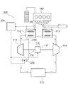
- FIG. 1 A configuration of a waste heat regeneration system 100 according to Embodiment 1 of the present invention is shown in FIG.
- the Rankine cycle apparatus 110 of the waste heat regeneration system 100 includes a pump 111, a cooling water boiler 112, an exhaust gas boiler 113, an expander 114, and a condenser 115, which are sequentially connected in a ring shape to form a closed circuit.
- the pump 111 pumps the working fluid.
- the cooling water boiler 112 is a first heat exchanger, and heats the working fluid by exchanging heat with cooling water of the engine 140 as a low-temperature heat source that is a heating medium.
- the exhaust gas boiler 113 is a second heat exchanger, and heats the working fluid by exchanging heat with exhaust gas discharged from the engine 140 as a high-temperature heat source that is a heating medium.
- the expander 114 expands the working fluid that is heated and vaporized in the cooling water boiler 112 and the exhaust gas boiler 113 to generate mechanical energy (power).
- the condenser 115 condenses the expanded working fluid.
- the cooling water of the engine 140 is a heating medium for the first heat exchanger, and the exhaust gas is a heating medium for the second heat exchanger. It is also possible to heat the heating medium of the second heat exchanger with the working fluid heated by the exhaust gas.
- the exhaust gas has a high temperature and rises quickly after the engine 140 is started. Therefore, the temperature of the exhaust gas boiler 113 can be raised faster than that of the cooling water boiler 112.
- the pump 111 and the expander 114 share the same drive shaft 116, and a motor generator 117 is connected in the middle of the drive shaft 116.
- the motor generator 117 functions as a drive source for the pump 111 and the expander 114 and, when the drive shaft 116 is driven by mechanical energy generated by the expander 114, converts the rotational driving force into electric power. Function as.
- the motor generator 117 is electrically connected to a control unit 150 that is a control means for controlling the operation of the waste heat regeneration system 100.
- a one-way clutch 120 as a power cut-off means is interposed between the motor generator 117 and the pump 111, and transmits a one-way rotational driving force from the motor generator 117.
- One end of a first bypass passage 118 that bypasses the pump 111 and the condenser 115 is connected between the pump 111 and the cooling water boiler 112, and the other end of the first bypass passage 118 is connected to the expander 114. It is connected between the capacitor 115.
- a three-way valve 119 as a first on-off valve is interposed at the other end of the first bypass flow path 118. The pressure loss of the first bypass passage 118 is sufficiently smaller than those of the pump 111 and the condenser 115.
- the three-way valve 119 is electrically connected to the control unit 150.
- Control unit 150 controls the rotation direction (forward / reverse rotation) of motor generator 117 based on temperature information acquired from temperature sensor 160 for measuring the temperature of the cooling water heated by the waste heat of engine 140.
- the rotational direction of the pump 111 and the expander 114 is controlled, and the open / close state of the first bypass flow path 118 is controlled by opening / closing the three-way valve 119 as the first open / close valve.
- the waste heat regeneration system 100 performs Rankine cycle operation when the coolant temperature of the engine 140 is equal to or higher than a predetermined value Th.
- the control unit 150 serving as a control unit is configured to drive the motor generator 117 in the forward direction when the coolant temperature of the engine 140 acquired from the temperature sensor 160 is equal to or higher than a predetermined value Th, thereby driving the pump 111 and the expander.
- the three-way valve 119 serving as the first on-off valve causes the condenser 115 and the expander 114 to communicate with each other, thereby closing the first bypass flow path 118.
- the working fluid pumped from the pump 111 toward the cooling water boiler 112 is heated from the cooling water of the engine 140 and the exhaust gas discharged from the engine 140 in the process of flowing through the cooling water boiler 112 and the exhaust gas boiler 113. Is absorbed to become a high-temperature gas and expands in the expander 114.
- the first bypass flow path 118 is in a closed state, the working fluid exiting the expander 114 flows into the condenser 115.
- the working fluid that has released heat in the process of being condensed in the condenser 115 is transferred toward the cooling water boiler 112 by the pump 111.
- the expander 114 is driven to rotate forward by the expansion of the working fluid, the motor generator 117 and the pump 111 are driven to rotate forward by the mechanical energy generated by the expansion.
- the waste heat regeneration system 100 performs a cooling water heating cycle operation in which the working fluid is circulated from the exhaust gas boiler 113 to the cooling water boiler 112.
- the control unit 150 serving as a control unit reverses the expander 114 by driving the motor generator 117 to rotate reversely when the coolant temperature of the engine 140 acquired from the temperature sensor 160 is less than a predetermined value Th.
- the three-way valve 119 serving as the first on-off valve is rotated, and the first bypass passage 118 is opened by bringing the first bypass passage 118 and the expander 114 into communication with each other. Allow circulation of working fluid to 118.
- the expander 114 has a structure in which the suction port and the discharge port of the compressor are connected in reverse. For this reason, when the expander 114 is driven to rotate in the reverse direction, the expander 114 serves as a compressor as a circulation means, and pumps the working fluid toward the exhaust gas boiler 113.
- the expander 114 is driven in reverse rotation by mechanical energy generated by a motor generator 117 as a drive source, and the motor generator 117 functions as a drive source of the expander 114. Further, the one-way clutch 120 blocks the reverse rotation (in the other direction) driving force from the motor generator 117, and the pump 111 is not driven.
- a closed circuit is formed in which the working fluid flows in the order of the expander 114 ⁇ the exhaust gas boiler 113 ⁇ the cooling water boiler 112 ⁇ the first bypass flow path 118 ⁇ the expander 114, as indicated by a dashed line arrow in the figure.
- the working fluid pumped from the expander 114 toward the exhaust gas boiler 113 absorbs heat from the exhaust gas flowing into the exhaust gas boiler 113 and discharged from the engine 140 to become a high-temperature gas, and then absorbs the absorbed heat.
- the working fluid when the coolant temperature of the engine 140 is less than the predetermined value Th, the working fluid is circulated from the exhaust gas boiler 113 toward the coolant boiler 112.
- the cooling water heating cycle operation is performed.
- a closed circuit is formed in which the working fluid flows in the order of the expander 114 ⁇ the exhaust gas boiler 113 ⁇ the cooling water boiler 112 ⁇ the first bypass flow path 118 ⁇ the expander 114.
- the working fluid that has absorbed heat in the exhaust gas boiler 113 immediately flows into the cooling water boiler 112 with almost no loss of the absorbed heat, and gives heat to the cooling water of the engine 140.
- the cooling water temperature is low, such as when the engine 140 is started, the heat of the exhaust gas can be efficiently transmitted to the cooling water, and the cooling water temperature can be quickly and efficiently increased. As a result, the fuel consumption of the engine 140 is improved.
- the expander 114 functions as a blower for transferring the working fluid. Therefore, the exhaust gas boiler 113 ⁇ the expander 114 ⁇ the first The working fluid circulates in the order of 1 bypass flow path 118 ⁇ cooling water boiler 112 ⁇ exhaust gas boiler 113, and heat of the exhaust gas can be transmitted to the cooling water. However, since the working fluid that has absorbed heat in the exhaust gas boiler 113 loses part of the heat absorbed in the process of flowing through the expander 114 and the first bypass flow path 118, the heat of the exhaust gas is transmitted to the cooling water. Efficiency decreases.
- the expander 114 is driven to rotate in the forward direction, an expansion process of the working fluid is performed inside the expander 114, and an overexpansion loss occurs. Furthermore, since the working fluid hardly flows into the condenser 115 and the pump 111, the working fluid in the section stays, and the lubricating oil contained in the working fluid is trapped. Therefore, although the temperature of the working fluid flowing into the expander 114 is high, the return of oil to the expander 114 is reduced, and the expander 114 is burdened.
- the expander 114 is driven in reverse rotation, so that the exhaust gas boiler 113 ⁇ the cooling water boiler 112 ⁇ the first bypass passage 118 ⁇ the expander 114 ⁇ the exhaust gas boiler.
- the working fluid circulates in the order of 113. Therefore, the working fluid that has absorbed heat in the exhaust gas boiler 113 immediately flows into the cooling water boiler 112 with almost no loss of the absorbed heat, and can efficiently transfer the heat of the exhaust gas to the cooling water. Further, since the expander 114 is driven to rotate in the reverse direction and used as a compressor, the working fluid is compressed in the expander 114 and an overcompression loss occurs.
- the power when the working fluid is transferred by the expander 114 can be kept small. Furthermore, since the working fluid flows from the expander 114 toward the exhaust gas boiler 113, the temperature of the working fluid flowing into the expander 114 is low. Therefore, even if there is little oil return to the expander 114, the expander 114 is not burdened. Further, the one-way clutch 120 does not drive the pump 111 during the cooling water temperature rising cycle operation, so that power consumption by the pump 111 can be eliminated.
- FIG. FIG. 2 shows the configuration of a waste heat regeneration system 200 according to Embodiment 2 of the present invention.
- the first bypass flow path 118 in the first embodiment bypasses the pump 111 and the condenser 115, but the first bypass flow path 218 in the second embodiment is between the pump 111 and the cooling water boiler 112.
- the one-way clutch 120 is omitted.
- the control unit 250 as the control means opens the electromagnetic on-off valve 219 as the first on-off valve, thereby bringing the first bypass flow path 218 into the communication state.
- the same reference numerals as those in FIG. 1 are the same or similar components, and thus detailed description thereof is omitted.
- the working fluid that has absorbed heat in the exhaust gas boiler 113 releases heat in the cooling water boiler 112 to heat the cooling water.
- the heat absorption amount in the exhaust gas boiler 113 exceeds the heat dissipation amount in the cooling water boiler 112, the entire circuit may be overheated.
- the expander 114 (functions as a compressor as a circulation means) ⁇ the exhaust gas boiler 113 ⁇ the cooling water boiler 112 ⁇ the first
- the condenser 115 excess heat that has not been absorbed by the cooling water boiler 112 is released by the condenser 115.
- the working fluid Since the working fluid flows in the order of the exhaust gas boiler 113 ⁇ the cooling water boiler 112 ⁇ the first bypass passage 218 ⁇ the condenser 115, the working fluid gives the heat absorbed by the exhaust gas boiler 113 to the cooling water boiler 112, and then the condenser 115. It flows into and releases excess heat. Therefore, there is no influence on the original purpose of heating / heating the cooling water.
- the reason for bypassing the pump 111 is to prevent an increase in mechanical energy required to drive the expander 114 due to the pump 111 becoming a throttle and generating a differential pressure.
- FIG. 3 shows the configuration of a waste heat regeneration system 300 according to Embodiment 3 of the present invention.
- the waste heat regeneration system 300 according to the third embodiment is an interior of the waste heat regeneration system 100 according to the first embodiment, which is driven in conjunction with the pump 111 and the expander 114 by sharing the drive shaft 316.
- An air conditioner compressor 320 for an air conditioner is added.
- the three-way valve 119 as the first on-off valve is provided.
- the electromagnetic on-off as the first on-off valve is provided in the middle of the first bypass passage 118 instead of the three-way valve 119.
- a valve 319 is interposed.
- a second end is connected between the pump 111 and the first bypass passage 118 via a three-way valve 322 as a second on-off valve, and the other end is connected between the pump 111 and the capacitor 115.
- a bypass channel 318 is provided.
- the second bypass flow path 318 forms a part of a closed circuit that allows the working fluid to be circulated by the pump 111 during the cooling water temperature rising cycle operation.
- the pump 111, the expander 114, and the air conditioner compressor 320 share the same drive shaft 316.
- a clutch 321 is interposed between the pump 111 and the air conditioner compressor 320 in the drive shaft 316.
- the clutch 321 blocks the linkage between the pump 111 and the expander 114 and the air conditioner compressor 320.
- the clutch 321 is electrically connected to a control unit 350 as control means.
- the control unit 350 controls the connection state of the clutch 321 based on the coolant temperature of the engine 140 and the air conditioner operation request from the driver.
- the waste heat regeneration system 300 performs Rankine cycle operation when the coolant temperature of the engine 140 is equal to or higher than a predetermined value Th.
- the control unit 350 serving as the control means causes the pump 111 and the expander 114 to rotate in the forward direction by driving the motor generator 117 in the forward direction when the coolant temperature is equal to or higher than the predetermined value Th.
- the electromagnetic on-off valve 319 as the on-off valve By closing the electromagnetic on-off valve 319 as the on-off valve, the first bypass flow path 118 is closed.
- the three-way valve 322 as the second on-off valve closes the second bypass flow path 318 by bringing the pump 111 and the cooling water boiler 112 into communication. If there is an air conditioner operation request and the air conditioner compressor 320 is driven, the air conditioner compressor 320 is driven in conjunction with the pump 111 and the expander 114 by connecting the clutch 321.
- a closed circuit in which the working fluid flows is formed in the order of the pump 111 ⁇ the cooling water boiler 112 ⁇ the exhaust gas boiler 113 ⁇ the expander 114 ⁇ the condenser 115 ⁇ the pump 111.
- the working fluid that has absorbed and vaporized heat in the cooling water boiler 112 and the exhaust gas boiler 113 generates mechanical energy in the process of expanding in the expander 114, and drives the expander 114 to rotate forward.
- the motor generator 117 and the pump 111 are driven to rotate in conjunction with the expansion, and the clutch 321 is connected.
- the compressor 320 is also driven forward.
- the waste heat regeneration system 300 circulates the working fluid from the exhaust gas boiler 113 to the cooling water boiler 112. Cooling water heating cycle operation is performed. Specifically, the control unit 350 serving as the control unit disengages the clutch 321 when the cooling water temperature is lower than the predetermined value Th and there is no air conditioner operation request and the air conditioner compressor 320 is not driven. The pump 111 and the expander 114 are disconnected from each other. That is, the driving force is prevented from being transmitted to the air conditioner compressor 320 via the drive shaft 316.
- the expander 114 is driven in reverse rotation by driving the motor generator 117 in reverse rotation to function as a compressor as circulation means, and the electromagnetic on-off valve 319 as the first on-off valve is opened to open the first bypass flow path. 118 is opened to allow the working fluid to circulate to the first bypass flow path 118.
- a closed circuit in which the working fluid flows is formed in the order of the expander 114 ⁇ the exhaust gas boiler 113 ⁇ the cooling water boiler 112 ⁇ the first bypass flow path 118 ⁇ the expander 114 as indicated by the one-dot broken line arrow in the figure. Is done.
- the working fluid that has absorbed heat in the exhaust gas boiler 113 immediately flows into the cooling water boiler 112 with almost no loss of the absorbed heat, and gives heat to the cooling water of the engine 140.
- the expander 114 and the pump 111 are reversely driven by mechanical energy generated by a motor generator 117 as a drive source.
- the three-way valve 322 as the second on-off valve opens the second bypass flow path 318 by bringing the second bypass flow path 318 and the pump 111 into communication with each other. Allow circulation. Therefore, the working fluid transferred by the pump 111 is circulated by a closed circuit including the second bypass channel 318. Further, since the clutch 321 is disengaged, the air conditioner compressor 320 is not driven.
- the waste heat regeneration system 300 circulates the working fluid from the cooling water boiler 112 toward the exhaust gas boiler 113. Cooling water heating cycle operation is performed.
- the control unit 350 serving as the control means connects the clutch 321 when the cooling water temperature is lower than a predetermined value Th and there is a request for operating the air conditioner to drive the air conditioner compressor 320.
- 320 is linked to the pump 111 and the expander 114. That is, the driving force is transmitted to the air conditioner compressor 320 via the drive shaft 316.
- the motor generator 117 is driven to rotate in the forward direction, so that the expander 114 and the pump 111 are driven to rotate in the forward direction, and the electromagnetic on-off valve 319 as the first on-off valve is opened to open the first bypass flow path 118.
- the circulation of the working fluid to one bypass flow path 118 is permitted.
- a closed circuit in which the working fluid flows in the order of the exhaust gas boiler 113 ⁇ the expander 114 ⁇ the first bypass passage 118 ⁇ the cooling water boiler 112 ⁇ the exhaust gas boiler 113 is formed in the direction opposite to the one-dot broken line arrow in the figure. Is done.
- the working fluid that has absorbed heat in the exhaust gas boiler 113 flows into the cooling water boiler 112 while losing a part of the heat absorbed in the process of flowing through the expander 114 and the first bypass flow path 118, so Give heat to.
- the expander 114 and the pump 111 are driven to rotate forward by mechanical energy generated by a motor generator 117 as a drive source.
- the three-way valve 322 serving as the second on-off valve opens the second bypass flow path 318 by bringing the second bypass flow path 318 and the pump 111 into communication with each other. Allow circulation. Therefore, the working fluid transferred by the pump 111 is circulated by a closed circuit including the second bypass channel 318. Further, since the clutch 321 is connected, the air conditioner compressor 320 is also driven to rotate forward.
- the exhaust gas boiler 113 starts.
- a first cooling water heating cycle operation is performed in which the working fluid is circulated toward the cooling water boiler 112.
- the working fluid circulates in the order of the expander 114 ⁇ the exhaust gas boiler 113 ⁇ the cooling water boiler 112 ⁇ the first bypass flow path 118 ⁇ the expander 114.
- the working fluid that has absorbed heat in the exhaust gas boiler 113 immediately flows into the cooling water boiler 112 with almost no loss of the absorbed heat, and gives heat to the cooling water of the engine 140.
- the second cooling water that circulates the working fluid from the cooling water gas boiler 112 to the exhaust gas boiler 113.
- a heating cycle operation is performed.
- the working fluid circulates in the order of the exhaust gas boiler 113 ⁇ the expander 114 ⁇ the first bypass passage 118 ⁇ the cooling water boiler 112 ⁇ the exhaust gas boiler 113.
- the working fluid that has absorbed heat in the exhaust gas boiler 113 flows into the cooling water boiler 122 while losing a part of the heat absorbed in the process of flowing through the expander 114 and the first bypass flow path 118, so Give heat to.
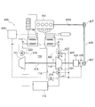
- FIG. 4 The configuration of a waste heat regeneration system 400 according to Embodiment 4 of the present invention is shown in FIG.
- the waste heat regeneration system 400 according to the fourth embodiment circulates the working fluid from the exhaust gas boiler 113 to the cooling water boiler 112 without causing the expander 114 to rotate reversely as in the first to third embodiments. Circulation direction changing means is provided.
- a three-way valve 423 is interposed between the exhaust gas boiler 113 and the expander 114, and a three-way valve 424 is interposed between the expander 114 and the condenser 115.
- One end of a flow path 425 is connected between the three-way valve 424 and the capacitor 115, and the other end of the flow path 425 is connected to the three-way valve 423.
- one end of a flow path 426 is connected between the exhaust gas boiler 113 and the three-way valve 423, and the other end of the flow path 426 is connected to the three-way valve 424.
- the circulation direction changing means in the present embodiment includes three-way valves 423 and 424 and flow paths 425 and 426.
- the pump 111 and the expander 114 share the same drive shaft 416.
- the drive shaft 416 is connected to the drive shaft 140a of the engine 140 via a pulley 427 and a belt 428.
- the drive shaft 416, the pulley 427, the belt 428, and the drive shaft 140a function as a mechanical energy transmission unit that returns mechanical energy generated by the expander 114 to the engine 140.
- the drive shaft 416 is also connected with an alternator 429 as power generation means for converting mechanical energy into electric power.
- a clutch 430 is interposed between the alternator 429 and the pulley 427. The clutch 430 blocks the linkage between the expander 114 and the drive shaft 140a of the engine 140. When the clutch 430 is connected, the drive shaft 140a of the engine 140 is driven in conjunction with the expander 114. .
- an electromagnetic on-off valve 319 as a first on-off valve is interposed in the middle of the first bypass flow path 118, and one end is passed through a three-way valve 322 as a second on-off valve.
- a second bypass flow path 318 is provided that is connected between the pump 111 and the first bypass flow path 118 and has the other end connected between the pump 111 and the capacitor 115.
- the electromagnetic on-off valve 319 as the first on-off valve, the three-way valve 322 as the second on-off valve, the three-way valves 423 and 424 constituting the circulation direction changing means, and the clutch 430 are electrically connected to the control unit 450 as the control means. It is connected.
- the waste heat regeneration system 400 performs Rankine cycle operation when the coolant temperature of the engine 140 is equal to or higher than a predetermined value Th.
- the control unit 450 serving as the control means drives the pump 111 and the expander 114 to rotate in the forward direction by supplying power from a battery (not shown) when the coolant temperature is equal to or higher than a predetermined value Th, and the first on-off valve.
- the first on-off flow path 118 is closed by closing the electromagnetic on-off valve 319.
- the three-way valve 322 as the second on-off valve closes the second bypass flow path 318 by bringing the pump 111 and the cooling water boiler 112 into communication.
- the three-way valve 423 closes the flow path 425 by bringing the exhaust gas boiler 113 and the expander 114 into communication with each other, and the three-way valve 424 includes the expander 114, the condenser 115, and the like. Is in a closed state by bringing the channel 426 into communication. Accordingly, the flow path A on one end side of the cooling water boiler 112 and the exhaust gas boiler 113 is connected to the flow path a on the suction side of the expander 114, and the flow path on the other end side of the cooling water boiler 112 and the exhaust gas boiler 113. B and the flow path b on the discharge side of the expander 114 are connected (with a pump 111 and a capacitor 115 interposed).
- a closed circuit in which the working fluid flows is formed in the order of the pump 111 ⁇ the cooling water boiler 112 ⁇ the exhaust gas boiler 113 ⁇ the expander 114 ⁇ the condenser 115 ⁇ the pump 111.
- the working fluid that has absorbed and vaporized heat in the cooling water boiler 112 and the exhaust gas boiler 113 generates mechanical energy in the process of expanding in the expander 114, and drives the expander 114 to rotate forward.
- the pump 111 is driven to rotate in conjunction with the expansion, and the alternator 429 generates power.
- clutch 430 When clutch 430 is engaged, drive shaft 140a of engine 140 is also driven, and mechanical energy generated in expander 114 is returned to engine 140. If the rotation speed of the expander 114 becomes too high to be suitable for assisting the rotation of the engine 140, the clutch 430 is disengaged to link the expander 114 with the drive shaft 140a of the engine 140. Cut off.
- the waste heat regeneration system 400 performs a cooling water heating cycle operation in which the working fluid is circulated from the exhaust gas boiler 113 to the cooling water boiler 112.
- the control unit 450 serving as a control unit is configured to drive the pump 111 and the expander 114 in the normal rotation by supplying electric power from a battery (not shown) when the cooling water temperature is lower than a predetermined value Th, and the first on-off valve. As a result, the first bypass flow path 118 is opened.
- the three-way valve 423 opens the flow path 425 to connect the cooling water boiler 112 and the suction side (upper side of the drawing surface) of the expander 114 via the first bypass flow path 118.
- the three-way valve 424 is in a state in which the discharge side (lower side of the sheet) of the expander 114 and the exhaust gas boiler 113 are in communication with each other by opening the flow path 426. Accordingly, the flow path A on one end side of the cooling water boiler 112 and the exhaust gas boiler 113 is connected to the flow path b on the discharge side of the expander 114, and the flow path on the other end side of the cooling water boiler 112 and the exhaust gas boiler 113. B and the flow path a on the suction side of the expander 114 are connected (via the first bypass flow path 118).
- the working fluid that has absorbed heat in the exhaust gas boiler 113 immediately flows into the cooling water boiler 112 with almost no loss of the absorbed heat, and gives heat to the cooling water of the engine 140.
- the three-way valve 322 as the second on-off valve opens the second bypass flow path 318 by connecting the second bypass flow path 318 and the pump 111, and the working fluid of the pump 111 that is driven to rotate in the forward direction. Allow circulation. Therefore, the working fluid transferred by the pump 111 is circulated by a closed circuit including the second bypass channel 318. Further, when clutch 430 is engaged, drive shaft 140a of engine 140 is also driven.
- the circulation direction changing means configured by the three-way valves 423 and 424 and the flow paths 425 and 426 is directed from the cooling water boiler 112 to the exhaust gas boiler 113.
- the Rankine cycle operation for circulating the working fluid and the cooling water heating cycle operation for circulating the working fluid from the exhaust gas boiler 113 to the cooling water boiler 112 are switched.
- the reason for bypassing the pump 111 as in the first to third embodiments is to prevent an increase in mechanical energy required to drive the expander 114.
- FIG. 5 shows the configuration of a waste heat regeneration system 500 according to Embodiment 5 of the present invention.
- the circulation direction changing means includes a three-way valve 423 and a three-way valve 424 interposed in the suction-side flow path a and the discharge-side flow path b of the expander 114, a flow path 425 and a flow path 426, respectively.
- the circulation direction changing means in the fifth embodiment is configured by the three-way valve 531 and the three-way valve 532 interposed in the flow path A on one end side of the cooling water boiler 112 and the exhaust gas boiler 113 connected in series,
- the three-way valve 533 and the three-way valve 534 interposed in the flow path B on the other end side, and the flow path 535 and the flow path 536 are configured.
- a three-way valve 531 and a three-way valve 532 are interposed between the exhaust gas boiler 113 and the expander 114, and a three-way valve 533 and a three-way valve 534 are disposed between one end of the first bypass passage 118 and the cooling water boiler 112. Is interposed.
- the three-way valve 531 and the three-way valve 533 are connected by a flow path 535, and the three-way valve 532 and the three-way valve 534 are connected by a flow path 536.
- the circulation direction changing means in the present embodiment is constituted by three-way valves 531, 532, 533, 534 and flow paths 535, 536.
- a three-way valve 519 as a first on-off valve is interposed at one end of the first bypass flow path 118.
- the pump 111 and the expander 114 share the same drive shaft 116, and a motor generator 117 is connected to the drive shaft 116.
- a clutch 537 is interposed between the motor generator 117 and the pump 111. The clutch 537 shuts off the interlock between the pump 111 and the expander 114, and the pump 111 is driven in conjunction with the expander 114 when the clutch 537 is connected.
- the three-way valve 519 as the first on-off valve, the three-way valves 531, 532, 533, 534 constituting the circulation direction changing means, the motor generator 117, and the clutch 537 are electrically connected to the control unit 550 as the control means. Yes.
- the waste heat regeneration system 500 performs Rankine cycle operation when the coolant temperature of the engine 140 is equal to or higher than a predetermined value Th.
- the control unit 550 serving as a control unit rotates the pump 111 and the expander 114 in the forward direction by driving the motor generator 117 in the forward direction and connecting the clutch 537 when the coolant temperature is equal to or higher than the predetermined value Th.
- a three-way valve 519 serving as a first on-off valve closes the first bypass flow path 118 by bringing the pump 111 and the cooling water boiler 112 into communication.
- the three-way valve 531 and the three-way valve 532 communicate with the exhaust gas boiler 113 and the expander 114, and the three-way valve 533 and the three-way valve 534 connect the pump 111 and the cooling water boiler 112 to each other. Communicate. Thereby, the flow path 535 and the flow path 536 are closed. Accordingly, the flow path A on one end side of the cooling water boiler 112 and the exhaust gas boiler 113 is connected to the flow path a on the suction side of the expander 114, and the flow path on the other end side of the cooling water boiler 112 and the exhaust gas boiler 113. B and the flow path b on the discharge side of the expander 114 are connected (with a pump 111 and a capacitor 115 interposed).
- a closed circuit in which the working fluid flows is formed in the order of the pump 111 ⁇ the cooling water boiler 112 ⁇ the exhaust gas boiler 113 ⁇ the expander 114 ⁇ the condenser 115 ⁇ the pump 111.
- the working fluid that has absorbed and vaporized heat in the cooling water boiler 112 and the exhaust gas boiler 113 generates mechanical energy in the process of expanding in the expander 114, and drives the expander 114 to rotate forward.
- the waste heat regeneration system 500 performs a cooling water heating cycle operation in which the working fluid is circulated from the exhaust gas boiler 113 to the cooling water boiler 112.
- the control unit 550 serving as a control unit causes the expander 114 to rotate in the forward direction by driving the motor generator 117 in the forward direction when the coolant temperature is lower than the predetermined value Th, and also disconnects the clutch 537.
- the interlock between the pump 111 and the expander 114 is cut off so that the pump 111 is not driven.
- a three-way valve 519 serving as a first on-off valve opens the first bypass flow path 118 by bringing the first bypass flow path 118 and the expander 114 into communication. Further, in the circulation direction changing means, the three-way valve 531 and the three-way valve 533 communicate the discharge side of the expander 114 and the exhaust gas boiler 113 via the first bypass flow path 118 by opening the flow path 535. The three-way valve 532 and the three-way valve 534 are in a state in which the cooling water boiler 112 and the suction side of the expander 114 are in communication with each other by opening the flow path 536.
- the flow path A on one end side of the cooling water boiler 112 and the exhaust gas boiler 113 and the flow path b on the discharge side of the expander 114 are connected (via the first bypass flow path 118), and the cooling water boiler 112 is connected.
- the flow path B on the other end side of the exhaust gas boiler 113 and the flow path a on the suction side of the expander 114 are connected.
- the expander 114 ⁇ the first bypass flow path 118 ⁇ the three-way valve 533 ⁇ the flow path 535 ⁇ the three-way valve 531 ⁇ the exhaust gas boiler 113 ⁇ the cooling water boiler 122 ⁇ the three-way A closed circuit through which the working fluid flows is formed in the order of valve 534 ⁇ flow path 536 ⁇ three-way valve 532 ⁇ expander 114.
- the working fluid that has absorbed heat in the exhaust gas boiler 113 immediately flows into the cooling water boiler 112 with almost no loss of the absorbed heat, and gives heat to the cooling water of the engine 140.
- the circulation direction changing means configured by the three-way valves 531, 532, 533, 534 and the flow paths 535, 536 causes the cooling water boiler 112 to A Rankine cycle operation in which the working fluid is circulated toward the exhaust gas boiler 113 and a cooling water heating cycle operation in which the working fluid is circulated from the exhaust gas boiler 113 toward the cooling water boiler 112 are switched.
- the cooling water ascending cycle operation in which the working fluid is circulated from the exhaust gas boiler 113 toward the cooling water boiler 112 can be performed without driving the expander 114 to rotate in the reverse direction.
- the second embodiment and the third embodiment may be combined. That is, in the waste heat regeneration system 300 according to the third embodiment, a first bypass channel that bypasses only the pump 111 may be provided instead of the first bypass channel 118 that bypasses the pump 111 and the condenser 115. .
- an electromagnetic on-off valve as the first on-off valve may be provided in the middle of the first bypass flow path 118.
- the one-way clutch 120 may be omitted.
- the pump 111 is driven by the motor generator 117, but the communication between the condenser 115 and the expander 114 is interrupted by a three-way valve 119 as a first on-off valve. Therefore, the pump 111 is filled with the gas-phase working fluid and becomes idle.
- cooling water for cooling the auxiliary equipment of engine 140 may be used as a low-temperature heat source. Further, the working fluid may be directly heated by an auxiliary machine.
- the working fluid may be directly heated using a cylinder head of the engine 140 as a high-temperature heat source.
Abstract
廃熱回生システムは、ポンプと、冷却水ボイラと、排気ガスボイラと、膨張機と、コンデンサとから構成されるランキンサイクル装置を備える。また、第1バイパス流路と電磁開閉弁とを備える。コントロールユニットは、エンジンの冷却水温度が所定値Th未満の場合に、膨張機を逆回転駆動させると共に第1バイパス流路を開状態とすることにより、排気ガスボイラから冷却水ボイラへ向けて作動流体を循環させる冷却水昇温サイクル運転を行う。
Description
この発明は、廃熱回生システムに係り、特にランキンサイクルを利用した廃熱回生システムに関する。
車両用エンジンの廃熱から機械的エネルギー(動力)を回収するランキンサイクルを利用した廃熱回生システムが開発されている。一般的なランキンサイクルは、作動流体を圧送するポンプと、作動流体をエンジンの廃熱によって加熱する熱交換器と、加熱された作動流体を膨張させて機械的エネルギーを回収する膨張機と、膨張後の作動流体を凝縮させるコンデンサとから構成され、これらが順次環状に接続されて閉回路を形成している。
特許文献1には、第1熱交換器と第2熱交換器とを備えた廃熱回生システムが記載されている。特許文献1の図1を参照すると、この廃熱回生システムのランキンサイクル17は、作動流体をエンジンの冷却水と熱交換させて加熱する冷却水ボイラである第1熱交換器15と、作動流体をエンジン1から排出される排気ガスと熱交換させて加熱する排気ガスボイラである第2熱交換器3とを備えている。ポンプ4から圧送された作動流体は、第1熱交換器15及び第2熱交換器3において加熱されて熱を吸収し、膨張機5において膨張する過程で機械的エネルギーを発生させ、冷却器(コンデンサ)6において凝縮される過程で熱を放出する。
一般に、エンジン始動時等において、エンジン冷却水の温度が低い場合には、エンジンの燃費が悪くなる。そのため、特許文献2に記載の蒸気圧縮式冷凍機のヒートポンプ暖機モード(図6)では、エンジン冷却水の温度が低い場合に、圧縮機210で圧縮されて高温高圧となった作動流体を冷却水ボイラである加熱器320に流入させることにより、圧縮機210の仕事分に相当する熱によってエンジン冷却水を加熱する。
上述したように、エンジン始動時等において、エンジン冷却水の温度が低い場合には、エンジンの燃費が悪くなる。
特許文献1に記載の廃熱回生システムでは、第2熱交換器3で吸収した排気ガスの熱を冷却水に伝えてその温度を速やかに上昇させることができれば燃費を向上させることができるが、ランキンサイクル17内を循環する作動流体は、第2熱交換器3で吸収した熱を冷却器6で放出してしまうため、排気ガスの熱を効率的に冷却水に伝えることができない。そのため、冷却水の温度を速やかに上昇させることができず、エンジン1の燃費が悪くなってしまう。
また、特許文献2に記載の蒸気圧縮式冷凍機のヒートポンプ暖機モードでは、エンジン冷却水の温度が低い場合に、圧縮機210の仕事分に相当する熱によって冷却水を加熱するが、圧縮仕事を熱エネルギーに変換するため効率が悪い。
この発明はこのような問題点を解決するためになされたものであり、エンジン冷却水の温度が低い場合に、冷却水の温度を速やかに効率よく上昇させてエンジンの燃費を向上させることができる廃熱回生システムを提供することを目的とする。
上記の課題を解決するために、この発明に係る廃熱回生システムは、作動流体を圧送するポンプと、圧送された作動流体を低温熱源によって加熱する第1熱交換器と、第1熱交換器で加熱された作動流体を高温熱源によって加熱する第2熱交換器と、加熱された作動流体を膨張させて機械的エネルギーを回収する膨張機と、膨張後の作動流体を凝縮させるコンデンサとを順次回路上に配置したランキンサイクル装置を有する廃熱回生システムにおいて、エンジン冷却水の温度が所定値未満の場合に、循環手段により第2熱交換器から第1熱交換器へ向けて作動流体を循環させる冷却水昇温サイクル運転を行う。
この発明に係る廃熱回生システムによれば、エンジン冷却水の温度が低い場合に、冷却水の温度を速やかに効率よく上昇させてエンジンの燃費を向上させることができる。
以下、この発明の実施の形態について添付図面に基づいて説明する。
実施の形態1.
この発明の実施の形態1に係る廃熱回生システム100の構成を図1に示す。
廃熱回生システム100のランキンサイクル装置110は、ポンプ111と、冷却水ボイラ112と、排気ガスボイラ113と、膨張機114と、コンデンサ115とから構成され、これらが順次環状に接続されて閉回路を形成している。
ポンプ111は作動流体を圧送する。冷却水ボイラ112は第1熱交換器であり、作動流体を加熱媒体である低温熱源としてのエンジン140の冷却水と熱交換させて加熱する。排気ガスボイラ113は第2熱交換器であり、作動流体を加熱媒体である高温熱源としてのエンジン140から排出される排気ガスと熱交換させて加熱する。膨張機114は、冷却水ボイラ112及び排気ガスボイラ113において加熱されて気化した作動流体を膨張させて機械的エネルギー(動力)を発生させる。コンデンサ115は膨張後の作動流体を凝縮させる。
エンジン140の冷却水が第1熱交換器の加熱媒体であり、排気ガスが第2熱交換器の加熱媒体である。排気ガスによって加熱された作動流体によって第2熱交換器の加熱媒体を加熱することも可能である。排気ガスは高温であり、エンジン140の始動後早く昇温する。したがって、排気ガスボイラ113は冷却水ボイラ112に比べて、早く昇温させることが可能である。
ポンプ111と膨張機114とは同一の駆動軸116を共有しており、駆動軸116の途中には、モータジェネレータ117が接続されている。モータジェネレータ117は、ポンプ111及び膨張機114の駆動源として機能すると共に、膨張機114で発生する機械的エネルギーによって駆動軸116が駆動される場合には、回転駆動力を電力に変換する発電機として機能する。また、モータジェネレータ117は、廃熱回生システム100の動作を制御するための制御手段であるコントロールユニット150に電気的に接続されている。また、モータジェネレータ117とポンプ111との間には動力遮断手段としてのワンウェイクラッチ120が介在されており、モータジェネレータ117からの一方向の回転駆動力を伝達する。
ポンプ111と冷却水ボイラ112との間には、ポンプ111及びコンデンサ115をバイパスする第1バイパス流路118の一端が接続されており、第1バイパス流路118の他端は、膨張機114とコンデンサ115との間に接続されている。第1バイパス流路118の他端には、第1開閉弁としての三方弁119が介在される。第1バイパス流路118の圧力損失は、ポンプ111及びコンデンサ115のそれらに比べて十分小さい。三方弁119はコントロールユニット150に電気的に接続されている。
コントロールユニット150は、エンジン140の廃熱によって加熱された冷却水温度を計測するための温度センサ160から取得される温度情報に基づいて、モータジェネレータ117の回転方向(正回転・逆回転)を制御することによってポンプ111及び膨張機114の回転方向を制御すると共に、第1開閉弁としての三方弁119を開閉させることによって第1バイパス流路118の開閉状態を制御する。
次に、実施の形態1に係る廃熱回生システム100の動作について、エンジン140の冷却水温度が所定値Th以上の場合と未満の場合とに分けて説明する。
(冷却水温度が所定値Th以上の場合:ランキンサイクル運転)
廃熱回生システム100は、エンジン140の冷却水温度が所定値Th以上の場合には、ランキンサイクル運転を行う。詳細には、制御手段としてのコントロールユニット150は、温度センサ160から取得されるエンジン140の冷却水温度が所定値Th以上の場合に、モータジェネレータ117を正回転駆動させることによってポンプ111及び膨張機114を正回転駆動させると共に、第1開閉弁としての三方弁119はコンデンサ115と膨張機114とを連通する状態とすることによって第1バイパス流路118を閉状態とする。
廃熱回生システム100は、エンジン140の冷却水温度が所定値Th以上の場合には、ランキンサイクル運転を行う。詳細には、制御手段としてのコントロールユニット150は、温度センサ160から取得されるエンジン140の冷却水温度が所定値Th以上の場合に、モータジェネレータ117を正回転駆動させることによってポンプ111及び膨張機114を正回転駆動させると共に、第1開閉弁としての三方弁119はコンデンサ115と膨張機114とを連通する状態とすることによって第1バイパス流路118を閉状態とする。
このとき、ポンプ111から冷却水ボイラ112に向けて圧送された作動流体は、冷却水ボイラ112及び排気ガスボイラ113を流通する過程において、エンジン140の冷却水及びエンジン140から排出される排気ガスから熱を吸収して高温のガスとなり、膨張機114において膨張する。次に、第1バイパス流路118は閉状態であるため、膨張機114を出た作動流体は、コンデンサ115に流入する。コンデンサ115において凝縮される過程で熱を放出した作動流体は、ポンプ111によって冷却水ボイラ112に向けて移送される。膨張機114が作動流体の膨張によって正回転駆動されるようになると、膨張によって発生した機械的エネルギーによって、モータジェネレータ117及びポンプ111が正回転駆動される。
(冷却水温度が所定値Th未満の場合:冷却水昇温サイクル運転)
廃熱回生システム100は、エンジン140の冷却水温度が所定値Th未満の場合には、排気ガスボイラ113から冷却水ボイラ112へ向けて作動流体を循環させる冷却水昇温サイクル運転を行う。詳細には、制御手段としてのコントロールユニット150は、温度センサ160から取得されるエンジン140の冷却水温度が所定値Th未満の場合に、モータジェネレータ117を逆回転駆動させることによって膨張機114を逆回転駆動させると共に、第1開閉弁としての三方弁119は第1バイパス流路118と膨張機114とを連通する状態とすることによって第1バイパス流路118を開状態とし、第1バイパス流路118への作動流体の循環を許容する。膨張機114は、圧縮機の吸入口と吐出口とを逆に接続した構造を有するものである。そのため、膨張機114は逆回転駆動されると循環手段としての圧縮機としての役割を果たし、排気ガスボイラ113に向けて作動流体を圧送する。膨張機114は駆動源としてのモータジェネレータ117が発生する機械的エネルギーによって逆回転駆動され、モータジェネレータ117は膨張機114の駆動源として機能する。また、ワンウェイクラッチ120により、モータジェネレータ117からの逆回転(他方向)の駆動力は遮断され、ポンプ111は駆動されない。
廃熱回生システム100は、エンジン140の冷却水温度が所定値Th未満の場合には、排気ガスボイラ113から冷却水ボイラ112へ向けて作動流体を循環させる冷却水昇温サイクル運転を行う。詳細には、制御手段としてのコントロールユニット150は、温度センサ160から取得されるエンジン140の冷却水温度が所定値Th未満の場合に、モータジェネレータ117を逆回転駆動させることによって膨張機114を逆回転駆動させると共に、第1開閉弁としての三方弁119は第1バイパス流路118と膨張機114とを連通する状態とすることによって第1バイパス流路118を開状態とし、第1バイパス流路118への作動流体の循環を許容する。膨張機114は、圧縮機の吸入口と吐出口とを逆に接続した構造を有するものである。そのため、膨張機114は逆回転駆動されると循環手段としての圧縮機としての役割を果たし、排気ガスボイラ113に向けて作動流体を圧送する。膨張機114は駆動源としてのモータジェネレータ117が発生する機械的エネルギーによって逆回転駆動され、モータジェネレータ117は膨張機114の駆動源として機能する。また、ワンウェイクラッチ120により、モータジェネレータ117からの逆回転(他方向)の駆動力は遮断され、ポンプ111は駆動されない。
このとき、図中の一点破線の矢印で示されるように、膨張機114→排気ガスボイラ113→冷却水ボイラ112→第1バイパス流路118→膨張機114の順に作動流体が流れる閉回路が形成される。膨張機114から排気ガスボイラ113に向けて圧送された作動流体は、排気ガスボイラ113に流入してエンジン140から排出される排気ガスから熱を吸収して高温のガスとなった後、吸収した熱をほとんど失うことなく直ちに冷却水ボイラ112に流入し、エンジン140の冷却水に熱を与える。作動流体は排気ガスボイラ113で吸収した熱をほとんど失うことなく冷却水ボイラ112に到達するため、エンジン140の冷却水温度は速やかに効率よく上昇し、エンジン140の燃費が向上する。
以上説明したように、実施の形態1に係る廃熱回生システム100では、エンジン140の冷却水温度が所定値Th未満の場合には、排気ガスボイラ113から冷却水ボイラ112へ向けて作動流体を循環させる冷却水昇温サイクル運転が行われる。このとき、膨張機114→排気ガスボイラ113→冷却水ボイラ112→第1バイパス流路118→膨張機114の順に作動流体が流れる閉回路が形成される。排気ガスボイラ113で熱を吸収した作動流体は、吸収した熱をほとんど失うことなく直ちに冷却水ボイラ112に流入し、エンジン140の冷却水に熱を与える。これにより、エンジン140の始動時等の冷却水温度が低い場合に、排気ガスの熱を効率的に冷却水に伝え、冷却水温度を速やかに効率よく上昇させることができる。その結果、エンジン140の燃費が向上する。
尚、膨張機114を逆回転駆動させずに第1バイパス流路118を開状態とするだけでも、膨張機114が作動流体を移送する送風機として機能するため、排気ガスボイラ113→膨張機114→第1バイパス流路118→冷却水ボイラ112→排気ガスボイラ113の順に作動流体が循環し、排気ガスの熱を冷却水に伝えることができる。
しかしながら、排気ガスボイラ113で熱を吸収した作動流体は、膨張機114及び第1バイパス流路118を流通する過程で吸収した熱の一部を失ってしまうため、排気ガスの熱を冷却水に伝える際の効率が落ちる。
また、膨張機114が正回転駆動されるため、膨張機114の内部では作動流体の膨張工程が行われて過膨張損失が発生する。
さらに、コンデンサ115及びポンプ111には作動流体がほとんど流入しないため、その区間内の作動流体が滞留してしまい、作動流体中に含まれる潤滑油がトラップされてしまう。そのため、膨張機114に流入する作動流体の温度が高いにも関わらず、膨張機114へのオイル戻りが少なくなり、膨張機114に負担がかかる。
これに対して、実施の形態1に係る廃熱回生システム100では、膨張機114を逆回転駆動させるため、排気ガスボイラ113→冷却水ボイラ112→第1バイパス流路118→膨張機114→排気ガスボイラ113の順に作動流体が循環する。そのため、排気ガスボイラ113で熱を吸収した作動流体は、吸収した熱をほとんど失うことなく直ちに冷却水ボイラ112に流入し、排気ガスの熱を効率的に冷却水に伝えることができる。
また、膨張機114を逆回転駆動させて圧縮機として使用するため、膨張機114の内部では作動流体の圧縮工程が行われて過圧縮損失が発生するが、一般的な膨張機の過圧縮損失は過膨張損失よりも小さいため、膨張機114によって作動流体を移送する際の動力を小さく抑えることができる。
さらに、膨張機114から排気ガスボイラ113の方向に作動流体が流れるため、膨張機114に流入する作動流体の温度が低い。そのため、膨張機114へのオイル戻りが少なくても、膨張機114に負担がかからない。
また、ワンウェイクラッチ120により、冷却水昇温サイクル運転時にはポンプ111が駆動されず、ポンプ111による動力消費をなくすことが出来る。
実施の形態2.
この発明の実施の形態2に係る廃熱回生システム200の構成を図2に示す。
実施の形態1における第1バイパス流路118は、ポンプ111及びコンデンサ115をバイパスしていたが、実施の形態2における第1バイパス流路218は、ポンプ111と冷却水ボイラ112との間と、ポンプ111とコンデンサ115との間を連通させることにより、ポンプ111のみをバイパスする。ワンウェイクラッチ120は、省かれている。冷却水昇温サイクル運転時には、制御手段としてのコントロールユニット250が第1開閉弁としての電磁開閉弁219を開弁することで、第1バイパス流路218を連通状態とする。尚、以降の実施の形態の説明において、図1の参照符号と同一の符号は同一又は同様の構成要素であるので、その詳細な説明は省略する。
実施の形態1に係る廃熱回生システム100の冷却水昇温サイクル運転時には、排気ガスボイラ113で熱を吸収した作動流体が冷却水ボイラ112で熱を放出することによって冷却水が加熱される。しかしながら、排気ガスボイラ113での吸熱量が冷却水ボイラ112での放熱量を上回る場合には、回路全体が過熱されてしまう虞がある。
実施の形態2に係る廃熱回生システム200では、図中の1点破線で示されるように、膨張機114(循環手段としての圧縮機として機能する)→排気ガスボイラ113→冷却水ボイラ112→第1バイパス流路218→コンデンサ115→膨張機114の順に作動流体が循環する過程において、冷却水ボイラ112で吸収されなかった過剰な熱は、コンデンサ115において放出される。これにより、作動流体の排気ガスボイラ113での吸熱量が冷却水ボイラ112での放熱量を上回る場合でも、回路全体が過熱されるのを防ぐことができる。尚、排気ガスボイラ113→冷却水ボイラ112→第1バイパス流路218→コンデンサ115の順に作動流体が流れるため、作動流体は排気ガスボイラ113で吸収した熱を冷却水ボイラ112に与えた後に、コンデンサ115に流入して余分な熱を放出する。そのため、冷却水を加熱・昇温するという本来の目的への影響はない。また、ポンプ111をバイパスする理由は、ポンプ111が絞りとなって差圧が生じることにより、膨張機114が駆動されるのに必要な機械的エネルギーが増加するのを防ぐためである。
実施の形態3.
この発明の実施の形態3に係る廃熱回生システム300の構成を図3に示す。
実施の形態3に係る廃熱回生システム300は、実施の形態1に係る廃熱回生システム100において、ポンプ111及び膨張機114と駆動軸316を共有することによってそれらと連動して駆動される車内エアコン用の空調機コンプレッサ320を追加している。また、実施の形態1では第1開閉弁としての三方弁119を備えていたが、本実施形態では三方弁119の代わりに、第1バイパス流路118の途中に第1開閉弁としての電磁開閉弁319を介在させている。さらに、一端が第2開閉弁としての三方弁322を介して、ポンプ111と第1バイパス流路118との間に接続され、他端がポンプ111とコンデンサ115との間に接続される第2バイパス流路318を備える。第2バイパス流路318は、冷却水昇温サイクル運転時にポンプ111による作動流体の循環を許容する閉回路の一部をなす。運転者からのエアコン稼働要求により空調機コンプレッサ320を駆動させる際には、駆動軸316を逆回転させることはできない。そのため、冷却水を昇温させながら空調機コンプレッサ320を駆動させる場合には、膨張機114、ポンプ111、及び空調機コンプレッサ320を正回転駆動させる。
ポンプ111、膨張機114、及び空調機コンプレッサ320は、同一の駆動軸316を共有している。駆動軸316におけるポンプ111と空調機コンプレッサ320との間には、クラッチ321が介在されている。クラッチ321は、ポンプ111及び膨張機114と空調機コンプレッサ320との連動を遮断するものであり、クラッチ321が繋がっている状態では、空調機コンプレッサ320がポンプ111及び膨張機114に連動して駆動される。また、クラッチ321は、制御手段としてのコントロールユニット350に電気的に接続されている。コントロールユニット350は、エンジン140の冷却水温度及び運転者からのエアコン稼働要求に基づいて、クラッチ321の接続状態を制御する。
次に、実施の形態3に係る廃熱回生システム300の動作について、冷却水温度が所定値Th以上の場合と、冷却水温度が所定値Th未満であり、かつエアコン稼働要求がない場合と、冷却水温度が所定値Th未満であり、かつエアコン稼働要求がある場合との3つに分けて説明する。
(冷却水温度が所定値Th以上の場合:ランキンサイクル運転)
廃熱回生システム300は、エンジン140の冷却水温度が所定値Th以上の場合には、ランキンサイクル運転を行う。詳細には、制御手段としてのコントロールユニット350は、冷却水温度が所定値Th以上の場合に、モータジェネレータ117を正回転駆動させることによってポンプ111及び膨張機114を正回転駆動させると共に、第1開閉弁としての電磁開閉弁319を閉じることで第1バイパス流路118を閉状態とする。第2開閉弁としての三方弁322はポンプ111と冷却水ボイラ112とを連通する状態とすることで、第2バイパス流路318を閉状態とする。また、エアコン稼働要求があり空調機コンプレッサ320を駆動させるのであれば、クラッチ321を繋ぐことによって空調機コンプレッサ320をポンプ111及び膨張機114に連動して駆動させる。
廃熱回生システム300は、エンジン140の冷却水温度が所定値Th以上の場合には、ランキンサイクル運転を行う。詳細には、制御手段としてのコントロールユニット350は、冷却水温度が所定値Th以上の場合に、モータジェネレータ117を正回転駆動させることによってポンプ111及び膨張機114を正回転駆動させると共に、第1開閉弁としての電磁開閉弁319を閉じることで第1バイパス流路118を閉状態とする。第2開閉弁としての三方弁322はポンプ111と冷却水ボイラ112とを連通する状態とすることで、第2バイパス流路318を閉状態とする。また、エアコン稼働要求があり空調機コンプレッサ320を駆動させるのであれば、クラッチ321を繋ぐことによって空調機コンプレッサ320をポンプ111及び膨張機114に連動して駆動させる。
このとき、ポンプ111→冷却水ボイラ112→排気ガスボイラ113→膨張機114→コンデンサ115→ポンプ111の順に作動流体が流れる閉回路が形成される。冷却水ボイラ112及び排気ガスボイラ113で熱を吸収して気化した作動流体は、膨張機114において膨張する過程で機械的エネルギーを発生させ、膨張機114を正回転駆動させる。気相の作動流体の膨張によって膨張機114が正回転駆動されるようになると、それに連動してモータジェネレータ117及びポンプ111が正回転駆動され、クラッチ321が繋がれている場合には、空調機コンプレッサ320も正回転駆動される。
(冷却水温度が所定値Th未満であり、かつエアコン稼働要求がない場合:第1の冷却水昇温サイクル運転)
廃熱回生システム300は、エンジン140の冷却水温度が所定値Th未満の場合に、エアコン稼働要求がないのであれば、排気ガスボイラ113から冷却水ボイラ112へ向けて作動流体を循環させる第1の冷却水昇温サイクル運転を行う。詳細には、制御手段としてのコントロールユニット350は、冷却水温度が所定値Th未満であり、かつエアコン稼働要求がなく空調機コンプレッサ320を駆動させない場合に、クラッチ321を切ることによって空調機コンプレッサ320とポンプ111及び膨張機114との連動を遮断する。すなわち、駆動力が駆動軸316を介して空調機コンプレッサ320に伝達されないようにする。その後、モータジェネレータ117を逆回転駆動させることによって膨張機114を逆回転駆動させ、循環手段としての圧縮機として機能させると共に、第1開閉弁としての電磁開閉弁319を開けて第1バイパス流路118を開状態とし、第1バイパス流路118への作動流体の循環を許容する。
廃熱回生システム300は、エンジン140の冷却水温度が所定値Th未満の場合に、エアコン稼働要求がないのであれば、排気ガスボイラ113から冷却水ボイラ112へ向けて作動流体を循環させる第1の冷却水昇温サイクル運転を行う。詳細には、制御手段としてのコントロールユニット350は、冷却水温度が所定値Th未満であり、かつエアコン稼働要求がなく空調機コンプレッサ320を駆動させない場合に、クラッチ321を切ることによって空調機コンプレッサ320とポンプ111及び膨張機114との連動を遮断する。すなわち、駆動力が駆動軸316を介して空調機コンプレッサ320に伝達されないようにする。その後、モータジェネレータ117を逆回転駆動させることによって膨張機114を逆回転駆動させ、循環手段としての圧縮機として機能させると共に、第1開閉弁としての電磁開閉弁319を開けて第1バイパス流路118を開状態とし、第1バイパス流路118への作動流体の循環を許容する。
このとき、図中に1点破線の矢印で示されるように、膨張機114→排気ガスボイラ113→冷却水ボイラ112→第1バイパス流路118→膨張機114の順に作動流体が流れる閉回路が形成される。排気ガスボイラ113で熱を吸収した作動流体は、吸収した熱をほとんど失うことなく直ちに冷却水ボイラ112に流入し、エンジン140の冷却水に熱を与える。膨張機114及びポンプ111は、駆動源としてのモータジェネレータ117が発生する機械的エネルギーによって逆回転駆動される。第2開閉弁としての三方弁322は第2バイパス流路318とポンプ111とを連通する状態とすることによって、第2バイパス流路318を開状態とし、逆回転駆動されるポンプ111による作動流体の循環を許容する。したがって、ポンプ111によって移送された作動流体は、第2バイパス流路318を含む閉回路によって循環される。また、クラッチ321が切られているため、空調機用コンプレッサ320は駆動されない。
(冷却水温度が所定値Th未満であり、かつエアコン稼働要求がある場合:第2の冷却水昇温サイクル運転)
廃熱回生システム300は、エンジン140の冷却水温度が所定値Th未満の場合に、エアコン稼働要求があるのであれば、冷却水ボイラ112から排気ガスボイラ113へ向けて作動流体を循環させる第2の冷却水昇温サイクル運転を行う。詳細には、制御手段としてのコントロールユニット350は、冷却水温度が所定値Th未満であり、かつエアコン稼働要求があり空調機コンプレッサ320を駆動させる場合に、クラッチ321を繋ぐことによって、空調機コンプレッサ320をポンプ111及び膨張機114に連動させる。すなわち、駆動力が駆動軸316を介して空調機コンプレッサ320に伝達されるようにする。その後、モータジェネレータ117を正回転駆動させることによって膨張機114及びポンプ111を正回転駆動させると共に、第1開閉弁としての電磁開閉弁319を開けて第1バイパス流路118を開状態とし、第1バイパス流路118への作動流体の循環を許容する。
廃熱回生システム300は、エンジン140の冷却水温度が所定値Th未満の場合に、エアコン稼働要求があるのであれば、冷却水ボイラ112から排気ガスボイラ113へ向けて作動流体を循環させる第2の冷却水昇温サイクル運転を行う。詳細には、制御手段としてのコントロールユニット350は、冷却水温度が所定値Th未満であり、かつエアコン稼働要求があり空調機コンプレッサ320を駆動させる場合に、クラッチ321を繋ぐことによって、空調機コンプレッサ320をポンプ111及び膨張機114に連動させる。すなわち、駆動力が駆動軸316を介して空調機コンプレッサ320に伝達されるようにする。その後、モータジェネレータ117を正回転駆動させることによって膨張機114及びポンプ111を正回転駆動させると共に、第1開閉弁としての電磁開閉弁319を開けて第1バイパス流路118を開状態とし、第1バイパス流路118への作動流体の循環を許容する。
このとき、図中の1点破線の矢印とは反対方向に、排気ガスボイラ113→膨張機114→第1バイパス流路118→冷却水ボイラ112→排気ガスボイラ113の順に作動流体が流れる閉回路が形成される。排気ガスボイラ113で熱を吸収した作動流体は、膨張機114及び第1バイパス流路118を流通する過程で吸収した熱の一部を失いつつも冷却水ボイラ112に流入し、エンジン140の冷却水に熱を与える。膨張機114及びポンプ111は、駆動源としてのモータジェネレータ117が発生する機械的エネルギーによって正回転駆動される。第2開閉弁としての三方弁322は第2バイパス流路318とポンプ111とを連通する状態とすることによって、第2バイパス流路318を開状態とし、正回転駆動されるポンプ111による作動流体の循環を許容する。したがって、ポンプ111によって移送された作動流体は、第2バイパス流路318を含む閉回路によって循環される。また、クラッチ321が繋がっているため、空調機コンプレッサ320も正回転駆動される。
以上説明したように、実施の形態3に係る廃熱回生システム300では、冷却水温度が所定値Th未満の場合に、エアコン要求がなく空調機コンプレッサ320を駆動させないのであれば、排気ガスボイラ113から冷却水ボイラ112へ向けて作動流体を循環させる第1の冷却水昇温サイクル運転が行われる。このとき、膨張機114→排気ガスボイラ113→冷却水ボイラ112→第1バイパス流路118→膨張機114の順に作動流体が循環する。排気ガスボイラ113で熱を吸収した作動流体は、吸収した熱をほとんど失うことなく直ちに冷却水ボイラ112に流入し、エンジン140の冷却水に熱を与える。
また、冷却水温度が所定値Th未満の場合に、エアコン要求があり空調機コンプレッサ320を駆動させるのであれば、冷却水ガスボイラ112から排気ガスボイラ113へ向けて作動流体を循環させる第2の冷却水昇温サイクル運転が行われる。このとき、排気ガスボイラ113→膨張機114→第1バイパス流路118→冷却水ボイラ112→排気ガスボイラ113の順に作動流体が循環する。排気ガスボイラ113で熱を吸収した作動流体は、膨張機114及び第1バイパス流路118を流通する過程で吸収した熱の一部を失いつつも冷却水ボイラ122に流入し、エンジン140の冷却水に熱を与える。
これらにより、エンジン140の冷却水温度が低い場合に、エアコン稼働要求がなく空調機コンプレッサ320を駆動させないのであれば、排気ガスの熱を効率的に冷却水に伝え、冷却水温度を速やかに効率よく上昇させることができる。また、エアコン稼働要求があり空調機コンプレッサ320を駆動させたとしても、効率はやや落ちるものの、排気ガスの熱を冷却水に伝え、冷却水温度を上昇させることができる。
実施の形態4.
この発明の実施の形態4に係る廃熱回生システム400の構成を図4に示す。
実施の形態4に係る廃熱回生システム400は、実施の形態1~3のように膨張機114を逆回転駆動させることなく排気ガスボイラ113から冷却水ボイラ112へ向けて作動流体を循環させるための循環方向変更手段を備える。
この発明の実施の形態4に係る廃熱回生システム400の構成を図4に示す。
実施の形態4に係る廃熱回生システム400は、実施の形態1~3のように膨張機114を逆回転駆動させることなく排気ガスボイラ113から冷却水ボイラ112へ向けて作動流体を循環させるための循環方向変更手段を備える。
排気ガスボイラ113と膨張機114との間には三方弁423が介在され、膨張機114とコンデンサ115との間には三方弁424が介在される。三方弁424とコンデンサ115との間には流路425の一端が接続され、流路425の他端は三方弁423に接続されている。また、排気ガスボイラ113と三方弁423との間には流路426の一端が接続され、流路426の他端は三方弁424に接続されている。本実施形態における循環方向変更手段は、三方弁423,424、流路425,426によって構成される。
ポンプ111及び膨張機114は、同一の駆動軸416を共有している。駆動軸416は、プーリ427及びベルト428を介してエンジン140の駆動軸140aに接続されている。駆動軸416、プーリ427、ベルト428、及び駆動軸140aは、膨張機114が発生させる機械的エネルギーをエンジン140に返還する機械的エネルギー伝達手段として機能する。また、駆動軸416には、機械的エネルギーを電力に変換する発電手段としてのオルタネータ429も接続されている。オルタネータ429とプーリ427との間には、クラッチ430が介在されている。クラッチ430は、膨張機114とエンジン140の駆動軸140aとの連動を遮断するものであり、クラッチ430が繋がっている状態では、エンジン140の駆動軸140aが膨張機114に連動して駆動される。
また、実施の形態3と同様に、第1バイパス流路118の途中には第1開閉弁としての電磁開閉弁319が介在されると共に、一端が第2開閉弁としての三方弁322を介してポンプ111と第1バイパス流路118との間に接続され、他端がポンプ111とコンデンサ115との間に接続される第2バイパス流路318を備える。
第1開閉弁としての電磁開閉弁319、第2開閉弁としての三方弁322、循環方向変更手段を構成する三方弁423,424、及びクラッチ430は、制御手段としてのコントロールユニット450に電気的に接続されている。
次に、実施の形態4に係る廃熱回生システム400の動作について、冷却水温度が所定値Th以上の場合と、冷却水温度が所定値Th未満の場合とに分けて説明する。
(冷却水温度が所定値Th以上の場合:ランキンサイクル運転)
廃熱回生システム400は、エンジン140の冷却水温度が所定値Th以上の場合には、ランキンサイクル運転を行う。詳細には、制御手段としてのコントロールユニット450は、冷却水温度が所定値Th以上の場合に、図示しないバッテリからの電力供給によってポンプ111及び膨張機114を正回転駆動させると共に、第1開閉弁としての電磁開閉弁319を閉じることで第1バイパス流路118を閉状態とする。第2開閉弁としての三方弁322はポンプ111と冷却水ボイラ112とを連通する状態とすることによって第2バイパス流路318を閉状態とする。また、循環方向変更手段においては、三方弁423は、排気ガスボイラ113と膨張機114とを連通する状態とすることによって流路425を閉状態とし、三方弁424は、膨張機114とコンデンサ115とを連通する状態とすることによって流路426を閉状態とする。したがって、冷却水ボイラ112及び排気ガスボイラ113の一端側の流路Aと膨張機114の吸入側の流路aとが接続されると共に、冷却水ボイラ112及び排気ガスボイラ113の他端側の流路Bと膨張機114の吐出側の流路bとが(ポンプ111及びコンデンサ115を介在して)接続される。
廃熱回生システム400は、エンジン140の冷却水温度が所定値Th以上の場合には、ランキンサイクル運転を行う。詳細には、制御手段としてのコントロールユニット450は、冷却水温度が所定値Th以上の場合に、図示しないバッテリからの電力供給によってポンプ111及び膨張機114を正回転駆動させると共に、第1開閉弁としての電磁開閉弁319を閉じることで第1バイパス流路118を閉状態とする。第2開閉弁としての三方弁322はポンプ111と冷却水ボイラ112とを連通する状態とすることによって第2バイパス流路318を閉状態とする。また、循環方向変更手段においては、三方弁423は、排気ガスボイラ113と膨張機114とを連通する状態とすることによって流路425を閉状態とし、三方弁424は、膨張機114とコンデンサ115とを連通する状態とすることによって流路426を閉状態とする。したがって、冷却水ボイラ112及び排気ガスボイラ113の一端側の流路Aと膨張機114の吸入側の流路aとが接続されると共に、冷却水ボイラ112及び排気ガスボイラ113の他端側の流路Bと膨張機114の吐出側の流路bとが(ポンプ111及びコンデンサ115を介在して)接続される。
このとき、ポンプ111→冷却水ボイラ112→排気ガスボイラ113→膨張機114→コンデンサ115→ポンプ111の順に作動流体が流れる閉回路が形成される。冷却水ボイラ112及び排気ガスボイラ113で熱を吸収して気化した作動流体は、膨張機114において膨張する過程で機械的エネルギーを発生させ、膨張機114を正回転駆動させる。気相の作動流体の膨張によって膨張機114が正回転駆動されるようになると、それに連動してポンプ111が正回転駆動されると共に、オルタネータ429では発電が行われる。また、クラッチ430が繋がれている場合には、エンジン140の駆動軸140aも駆動され、膨張機114で発生した機械的エネルギーがエンジン140に返還される。尚、膨張機114の回転数が高くなりすぎてエンジン140の回転を補助するのに適当でなくなった場合には、クラッチ430を切ることによって膨張機114とエンジン140の駆動軸140aとの連動を遮断する。
(冷却水温度が所定値Th未満の場合:冷却水昇温サイクル運転)
廃熱回生システム400は、エンジン140の冷却水温度が所定値Th未満の場合には、排気ガスボイラ113から冷却水ボイラ112へ向けて作動流体を循環させる冷却水昇温サイクル運転を行う。詳細には、制御手段としてのコントロールユニット450は、冷却水温度が所定値Th未満の場合に、図示しないバッテリからの電力供給によってポンプ111及び膨張機114を正回転駆動させると共に、第1開閉弁としての電磁開閉弁319を開くことで第1バイパス流路118を開状態とする。また、循環方向変更手段においては、三方弁423は、流路425を開状態とすることによって冷却水ボイラ112と膨張機114の吸入側(紙面上側)とを第1バイパス流路118を介して連通する状態とし、三方弁424は、流路426を開状態とすることによって膨張機114の吐出側(紙面下側)と排気ガスボイラ113とを連通する状態とする。したがって、冷却水ボイラ112及び排気ガスボイラ113の一端側の流路Aと膨張機114の吐出側の流路bとが接続されると共に、冷却水ボイラ112及び排気ガスボイラ113の他端側の流路Bと膨張機114の吸入側の流路aとが(第1バイパス流路118を介して)接続される。
廃熱回生システム400は、エンジン140の冷却水温度が所定値Th未満の場合には、排気ガスボイラ113から冷却水ボイラ112へ向けて作動流体を循環させる冷却水昇温サイクル運転を行う。詳細には、制御手段としてのコントロールユニット450は、冷却水温度が所定値Th未満の場合に、図示しないバッテリからの電力供給によってポンプ111及び膨張機114を正回転駆動させると共に、第1開閉弁としての電磁開閉弁319を開くことで第1バイパス流路118を開状態とする。また、循環方向変更手段においては、三方弁423は、流路425を開状態とすることによって冷却水ボイラ112と膨張機114の吸入側(紙面上側)とを第1バイパス流路118を介して連通する状態とし、三方弁424は、流路426を開状態とすることによって膨張機114の吐出側(紙面下側)と排気ガスボイラ113とを連通する状態とする。したがって、冷却水ボイラ112及び排気ガスボイラ113の一端側の流路Aと膨張機114の吐出側の流路bとが接続されると共に、冷却水ボイラ112及び排気ガスボイラ113の他端側の流路Bと膨張機114の吸入側の流路aとが(第1バイパス流路118を介して)接続される。
このとき、図中に1点破線の矢印で示されるように、膨張機114→三方弁424→流路426→排気ガスボイラ113→冷却水ボイラ112→第1バイパス流路118→流路425→三方弁423→膨張機114の順に作動流体が流れる閉回路が形成される。排気ガスボイラ113で熱を吸収した作動流体は、吸収した熱をほとんど失うことなく直ちに冷却水ボイラ112に流入し、エンジン140の冷却水に熱を与える。第2開閉弁としての三方弁322は第2バイパス流路318とポンプ111とを連通する状態とすることによって第2バイパス流路318を開状態とし、正回転駆動されるポンプ111による作動流体の循環を許容する。したがって、ポンプ111によって移送された作動流体は、第2バイパス流路318を含む閉回路によって循環される。また、クラッチ430が繋がれている場合には、エンジン140の駆動軸140aも駆動される。
以上説明したように、実施の形態4に係る廃熱回生システム400では、三方弁423,424、流路425,426によって構成される循環方向変更手段によって、冷却水ボイラ112から排気ガスボイラ113へ向けて作動流体を循環させるランキンサイクル運転と、排気ガスボイラ113から冷却水ボイラ112へ向けて作動流体を循環させる冷却水昇温サイクル運転とを切り替える。
これにより、実施の形態1~3のように膨張機114を逆回転駆動させることなく、排気ガスボイラ113から冷却水ボイラ112へ向けて作動流体を循環させる冷却水昇温サイクル運転を行うことができる。尚、実施の形態1~3と同様にポンプ111をバイパスする理由は、膨張機114を駆動するのに必要な機械的エネルギーが増加するのを防ぐためである。
これにより、実施の形態1~3のように膨張機114を逆回転駆動させることなく、排気ガスボイラ113から冷却水ボイラ112へ向けて作動流体を循環させる冷却水昇温サイクル運転を行うことができる。尚、実施の形態1~3と同様にポンプ111をバイパスする理由は、膨張機114を駆動するのに必要な機械的エネルギーが増加するのを防ぐためである。
実施の形態5.
この発明の実施の形態5に係る廃熱回生システム500の構成を図5に示す。
実施の形態4における循環方向変更手段は、膨張機114の吸入側の流路a及び吐出側の流路bにそれぞれ介在された三方弁423及び三方弁424と、流路425及び流路426とによって構成されていたが、実施の形態5における循環方向変更手段は、直列に接続された冷却水ボイラ112及び排気ガスボイラ113の一端側の流路Aに介在された三方弁531及び三方弁532と、他端側の流路Bに介在された三方弁533及び三方弁534と、流路535及び流路536とによって構成される。
この発明の実施の形態5に係る廃熱回生システム500の構成を図5に示す。
実施の形態4における循環方向変更手段は、膨張機114の吸入側の流路a及び吐出側の流路bにそれぞれ介在された三方弁423及び三方弁424と、流路425及び流路426とによって構成されていたが、実施の形態5における循環方向変更手段は、直列に接続された冷却水ボイラ112及び排気ガスボイラ113の一端側の流路Aに介在された三方弁531及び三方弁532と、他端側の流路Bに介在された三方弁533及び三方弁534と、流路535及び流路536とによって構成される。
排気ガスボイラ113と膨張機114との間には、三方弁531及び三方弁532が介在され、第1バイパス流路118の一端と冷却水ボイラ112との間には、三方弁533及び三方弁534が介在される。三方弁531と三方弁533とは流路535によって接続され、三方弁532と三方弁534とは流路536によって接続されている。本実施形態における循環方向変更手段は、三方弁531,532,533,534、及び流路535,536によって構成される。また、第1バイパス流路118の一端には、第1開閉弁としての三方弁519が介在される。
また、実施の形態1と同様に、ポンプ111と膨張機114とは同一の駆動軸116を共有しており、駆動軸116の途中にはモータジェネレータ117が接続されている。
モータジェネレータ117とポンプ111との間にはクラッチ537が介在されている。クラッチ537は、ポンプ111と膨張機114との連動を遮断するものであり、クラッチ537が繋がっている状態では、ポンプ111が膨張機114に連動して駆動される。
モータジェネレータ117とポンプ111との間にはクラッチ537が介在されている。クラッチ537は、ポンプ111と膨張機114との連動を遮断するものであり、クラッチ537が繋がっている状態では、ポンプ111が膨張機114に連動して駆動される。
第1開閉弁としての三方弁519、循環方向変更手段を構成する三方弁531,532,533,534、モータジェネレータ117、及びクラッチ537は、制御手段としてのコントロールユニット550に電気的に接続されている。
次に、実施の形態5に係る廃熱回生システム500の動作について、冷却水温度が所定値Th以上の場合と、冷却水温度が所定値Th未満の場合とに分けて説明する。
(冷却水温度が所定値Th以上の場合:ランキンサイクル運転)
廃熱回生システム500は、エンジン140の冷却水温度が所定値Th以上の場合には、ランキンサイクル運転を行う。詳細には、制御手段としてのコントロールユニット550は、冷却水温度が所定値Th以上の場合に、モータジェネレータ117を正回転駆動させると共にクラッチ537を繋ぐことによって、ポンプ111及び膨張機114を正回転駆動させる。第1開閉弁としての三方弁519は、ポンプ111と冷却水ボイラ112とを連通する状態とすることによって第1バイパス流路118を閉状態とする。また、循環方向変更手段においては、三方弁531及び三方弁532は、排気ガスボイラ113と膨張機114とを連通する状態とし、三方弁533及び三方弁534は、ポンプ111と冷却水ボイラ112とを連通する状態とする。これにより、流路535及び流路536は閉状態となる。したがって、冷却水ボイラ112及び排気ガスボイラ113の一端側の流路Aと膨張機114の吸入側の流路aとが接続されると共に、冷却水ボイラ112及び排気ガスボイラ113の他端側の流路Bと膨張機114の吐出側の流路bとが(ポンプ111及びコンデンサ115を介在して)接続される。
廃熱回生システム500は、エンジン140の冷却水温度が所定値Th以上の場合には、ランキンサイクル運転を行う。詳細には、制御手段としてのコントロールユニット550は、冷却水温度が所定値Th以上の場合に、モータジェネレータ117を正回転駆動させると共にクラッチ537を繋ぐことによって、ポンプ111及び膨張機114を正回転駆動させる。第1開閉弁としての三方弁519は、ポンプ111と冷却水ボイラ112とを連通する状態とすることによって第1バイパス流路118を閉状態とする。また、循環方向変更手段においては、三方弁531及び三方弁532は、排気ガスボイラ113と膨張機114とを連通する状態とし、三方弁533及び三方弁534は、ポンプ111と冷却水ボイラ112とを連通する状態とする。これにより、流路535及び流路536は閉状態となる。したがって、冷却水ボイラ112及び排気ガスボイラ113の一端側の流路Aと膨張機114の吸入側の流路aとが接続されると共に、冷却水ボイラ112及び排気ガスボイラ113の他端側の流路Bと膨張機114の吐出側の流路bとが(ポンプ111及びコンデンサ115を介在して)接続される。
このとき、ポンプ111→冷却水ボイラ112→排気ガスボイラ113→膨張機114→コンデンサ115→ポンプ111の順に作動流体が流れる閉回路が形成される。冷却水ボイラ112及び排気ガスボイラ113で熱を吸収して気化した作動流体は、膨張機114において膨張する過程で機械的エネルギーを発生させ、膨張機114を正回転駆動させる。
(冷却水温度が所定値Th未満の場合:冷却水昇温サイクル運転)
廃熱回生システム500は、エンジン140の冷却水温度が所定値Th未満の場合には、排気ガスボイラ113から冷却水ボイラ112へ向けて作動流体を循環させる冷却水昇温サイクル運転を行う。詳細には、制御手段としてのコントロールユニット550は、冷却水温度が所定値Th未満の場合に、モータジェネレータ117を正回転駆動させることによって膨張機114を正回転駆動させると共に、クラッチ537を切ることによってポンプ111と膨張機114との連動を遮断し、ポンプ111が駆動されないようにする。第1開閉弁としての三方弁519は、第1バイパス流路118と膨張機114とを連通する状態とすることによって第1バイパス流路118を開状態とする。また、循環方向変更手段においては、三方弁531及び三方弁533は、流路535を開状態とすることによって膨張機114の吐出側と排気ガスボイラ113とを第1バイパス流路118を介して連通する状態とし、三方弁532及び三方弁534は、流路536を開状態とすることによって冷却水ボイラ112と膨張機114の吸入側とを連通する状態とする。したがって、冷却水ボイラ112及び排気ガスボイラ113の一端側の流路Aと膨張機114の吐出側の流路bとが(第1バイパス流路118を介して)接続されると共に、冷却水ボイラ112及び排気ガスボイラ113の他端側の流路Bと膨張機114の吸入側の流路aとが接続される。
廃熱回生システム500は、エンジン140の冷却水温度が所定値Th未満の場合には、排気ガスボイラ113から冷却水ボイラ112へ向けて作動流体を循環させる冷却水昇温サイクル運転を行う。詳細には、制御手段としてのコントロールユニット550は、冷却水温度が所定値Th未満の場合に、モータジェネレータ117を正回転駆動させることによって膨張機114を正回転駆動させると共に、クラッチ537を切ることによってポンプ111と膨張機114との連動を遮断し、ポンプ111が駆動されないようにする。第1開閉弁としての三方弁519は、第1バイパス流路118と膨張機114とを連通する状態とすることによって第1バイパス流路118を開状態とする。また、循環方向変更手段においては、三方弁531及び三方弁533は、流路535を開状態とすることによって膨張機114の吐出側と排気ガスボイラ113とを第1バイパス流路118を介して連通する状態とし、三方弁532及び三方弁534は、流路536を開状態とすることによって冷却水ボイラ112と膨張機114の吸入側とを連通する状態とする。したがって、冷却水ボイラ112及び排気ガスボイラ113の一端側の流路Aと膨張機114の吐出側の流路bとが(第1バイパス流路118を介して)接続されると共に、冷却水ボイラ112及び排気ガスボイラ113の他端側の流路Bと膨張機114の吸入側の流路aとが接続される。
このとき、図中に1点破線の矢印で示されるように、膨張機114→第1バイパス流路118→三方弁533→流路535→三方弁531→排気ガスボイラ113→冷却水ボイラ122→三方弁534→流路536→三方弁532→膨張機114の順に作動流体が流れる閉回路が形成される。排気ガスボイラ113で熱を吸収した作動流体は、吸収した熱をほとんど失うことなく直ちに冷却水ボイラ112に流入し、エンジン140の冷却水に熱を与える。
以上説明したように、実施の形態5に係る廃熱回生システム500では、三方弁531,532,533,534、及び流路535,536によって構成される循環方向変更手段によって、冷却水ボイラ112から排気ガスボイラ113へ向けて作動流体を循環させるランキンサイクル運転と、排気ガスボイラ113から冷却水ボイラ112へ向けて作動流体を循環させる冷却水昇温サイクル運転とを切り替える。
これにより、実施の形態4と同様に、膨張機114を逆回転駆動させることなく、排気ガスボイラ113から冷却水ボイラ112へ向けて作動流体を循環させる冷却水昇サイクル運転を行うことができる。
これにより、実施の形態4と同様に、膨張機114を逆回転駆動させることなく、排気ガスボイラ113から冷却水ボイラ112へ向けて作動流体を循環させる冷却水昇サイクル運転を行うことができる。
その他の実施の形態.
実施の形態2と実施の形態3とを組み合わせてもよい。すなわち、実施の形態3に係る廃熱回生システム300おいて、ポンプ111及びコンデンサ115をバイパスする第1バイパス流路118の代わりに、ポンプ111のみをバイパスする第1バイパス流路を設けても良い。
実施の形態2と実施の形態3とを組み合わせてもよい。すなわち、実施の形態3に係る廃熱回生システム300おいて、ポンプ111及びコンデンサ115をバイパスする第1バイパス流路118の代わりに、ポンプ111のみをバイパスする第1バイパス流路を設けても良い。
実施の形態1において、第1開閉弁としての三方弁119の代わりに、第1バイパス流路118の途中に第1開閉弁としての電磁開閉弁を設けてもよい。
実施の形態1において、ワンウェイクラッチ120を省いてもよい。その場合、ポンプ111はモータジェネレータ117によって駆動されてしまうが、コンデンサ115と膨張機114との連通は第1開閉弁としての三方弁119によって絶たれている。したがって、ポンプ111は気相の作動流体で満たされて、空回りの状態となる。
実施の形態1~5において、低温熱源として、エンジン140の補機を冷却する冷却水を用いてもよい。また、補機によって作動流体を直接加熱してもよい。
実施の形態1~5において、高温熱源として、エンジン140のシリンダヘッドを用いて作動流体を直接加熱してもよい。
Claims (10)
- 作動流体を圧送するポンプと、圧送された前記作動流体を低温熱源によって加熱する第1熱交換器と、該第1熱交換器で加熱された前記作動流体を高温熱源によって加熱する第2熱交換器と、加熱された前記作動流体を膨張させて機械的エネルギーを回収する膨張機と、膨張後の前記作動流体を凝縮させるコンデンサとを順次回路上に配置したランキンサイクル装置を有する廃熱回生システムにおいて、
前記エンジン冷却水の温度が所定値未満の場合に、循環手段により前記第2熱交換器から前記第1熱交換器へ向けて前記作動流体を循環させる冷却水昇温サイクル運転を行う、廃熱回生システム。 - 前記循環手段は前記膨張機である、請求項1に記載の廃熱回生システム。
- 直列に接続された前記第1熱交換器と前記第2熱交換器の一端側と他端側の2つの流路と、前記循環手段の吸入側と吐出側の2つの流路との接続状態を切り替える循環方向変更手段を備え、
該循環方向変更手段によって、前記第1熱交換器から前記第2熱交換器へ向けて前記作動流体を循環させるランキンサイクル運転と、前記第2熱交換器から前記第1熱交換器へ向けて前記作動流体を循環させる冷却水昇温サイクル運転とを切り替える、請求項1又は2に記載の廃熱回生システム。 - 前記循環手段が発生させる機械的エネルギーを電力に変換する発電手段と、
前記循環手段が発生させる機械的エネルギーをエンジンに返還する機械的エネルギー伝達手段とをさらに備える、請求項3に記載の廃熱回生システム。 - 前記ポンプと前記第1熱交換器との間にその一端が接続されると共に、前記膨張機と前記コンデンサとの間にその他端が接続されることで前記ポンプ及び前記コンデンサをバイパスする第1バイパス流路と、
該第1バイパス流路の第1開閉弁と、
前記ポンプと前記第1バイパス流路の一端との間にその一端が接続されると共に、前記ポンプと前記コンデンサとの間にその他端が接続されることで前記ポンプをバイパスする第2バイパス流路と、
該第2バイパス流路の第2開閉弁と、
前記第1開閉弁及び前記第2開閉弁の開閉状態を制御する制御手段とをさらに備え、
該制御手段は、前記冷却水昇温度サイクル運転を行う際に、前記第1バイパス流路及び前記第2バイパス流路を開状態とするよう前記第1開閉弁及び前記第2開閉弁を制御して前記第1バイパス流路及び前記第2バイパス流路への前記作動流体の循環を許容する、請求項4に記載の廃熱回生システム。 - 前記膨張機を逆回転駆動させることによって前記循環手段とする、請求項2に記載の廃熱回生システム。
- 前記ポンプと前記第1熱交換器との間と、前記ポンプと前記膨張機との間とを連通することで少なくとも前記ポンプをバイパスする第1バイパス流路と、
該第1バイパス流路の第1開閉弁と、
前記膨張機の回転方向及び前記第1開閉弁の開閉状態を制御する制御手段とを備え、
該制御手段は、前記膨張機を逆回転駆動させて前記循環手段とすることによって該膨張機から前記第2熱交換器に向けて作動流体を圧送させると共に、前記第1バイパス流路を開状態とするよう前記第1開閉弁を制御して前記第1バイパス流路への前記作動流体の循環を許容することにより、前記第2熱交換器から前記第1熱交換器へ向けて前記作動流体を循環させる前記冷却水昇温サイクル運転を行う、請求項6に記載の廃熱回生システム。 - 前記第1バイパス流路は、前記ポンプと前記第1熱交換器との間と、前記膨張機と前記コンデンサとの間とを連通する、請求項7に記載の廃熱回生システム。
- 前記第1バイパス流路は、前記ポンプと前記第1熱交換器との間と、前記ポンプと前記コンデンサとの間とを連通する、請求項7に記載の廃熱回生システム。
- 前記膨張機に連動して駆動される空調機コンプレッサと、
前記膨張機と該空調機コンプレッサとの連動を遮断するクラッチ手段とをさらに備え、
前記制御手段は、前記エンジン冷却水の温度が所定値未満であり、かつ前記空調機コンプレッサを駆動させない場合に、前記クラッチ手段を制御して前記膨張機と前記空調機コンプレッサとの連動を遮断すると共に、前記第2熱交換器から前記第1熱交換器へ向けて前記作動流体を循環させる前記冷却水昇温サイクル運転を行う、請求項6~9のいずれか一項に記載の廃熱回生システム。
Priority Applications (1)
| Application Number | Priority Date | Filing Date | Title |
|---|---|---|---|
| JP2012508187A JP5333659B2 (ja) | 2010-03-29 | 2011-03-10 | 廃熱回生システム |
Applications Claiming Priority (2)
| Application Number | Priority Date | Filing Date | Title |
|---|---|---|---|
| JP2010075563 | 2010-03-29 | ||
| JP2010-075563 | 2010-03-29 |
Publications (1)
| Publication Number | Publication Date |
|---|---|
| WO2011122294A1 true WO2011122294A1 (ja) | 2011-10-06 |
Family
ID=44712018
Family Applications (1)
| Application Number | Title | Priority Date | Filing Date |
|---|---|---|---|
| PCT/JP2011/055650 WO2011122294A1 (ja) | 2010-03-29 | 2011-03-10 | 廃熱回生システム |
Country Status (2)
| Country | Link |
|---|---|
| JP (1) | JP5333659B2 (ja) |
| WO (1) | WO2011122294A1 (ja) |
Cited By (11)
| Publication number | Priority date | Publication date | Assignee | Title |
|---|---|---|---|---|
| JP2014118910A (ja) * | 2012-12-18 | 2014-06-30 | Fuji Heavy Ind Ltd | 車両用冷却装置 |
| FR3002279A1 (fr) * | 2013-02-20 | 2014-08-22 | Renault Sa | Systeme de recuperation de chaleur des gaz d'echappement dans un moteur a combustion interne |
| US20150089943A1 (en) * | 2013-10-02 | 2015-04-02 | Ford Global Technologies, Llc | Methods and systems for hybrid vehicle waste heat recovery |
| EP2865941A1 (de) * | 2013-10-22 | 2015-04-29 | Linde Aktiengesellschaft | Verwendung eines gewickelten Wärmeübertragers zur Erzeugung überhitzten Dampfs aus Verbrennungs- oder Abgasen bei Heizanlagen oder Verbrennungsmaschinen |
| JP2015083829A (ja) * | 2013-09-20 | 2015-04-30 | パナソニックIpマネジメント株式会社 | 発電制御装置、発電装置及びランキンサイクル装置の制御方法 |
| FR3057298A1 (fr) * | 2016-10-11 | 2018-04-13 | Peugeot Citroen Automobiles Sa | Ensemble de motorisation a boucle de rankine |
| WO2018153600A1 (de) * | 2017-02-23 | 2018-08-30 | Robert Bosch Gmbh | Abwärmerückgewinnungssystem sowie ein verfahren zum betreiben eines derartigen abwärmerückgewinnungssystems |
| US10662822B2 (en) | 2017-11-01 | 2020-05-26 | Honda Motor Co., Ltd. | Heat cycle system |
| WO2022203626A1 (en) * | 2021-03-24 | 2022-09-29 | Repg Enerji Sistemleri Sanayi Ve Ticaret Anonim Sirketi | An efficiency and comfort system for motorized vehicles |
| CN115234400A (zh) * | 2022-08-02 | 2022-10-25 | 安融能源技术(上海)有限公司 | 应用于船舶及海洋工程领域的余热发电系统 |
| US11535392B2 (en) * | 2019-03-18 | 2022-12-27 | Pratt & Whitney Canada Corp. | Architectures for hybrid-electric propulsion |
Families Citing this family (1)
| Publication number | Priority date | Publication date | Assignee | Title |
|---|---|---|---|---|
| JP2013180625A (ja) * | 2012-02-29 | 2013-09-12 | Mitsubishi Heavy Ind Ltd | 排熱回収型船舶推進装置およびその運用方法 |
Citations (5)
| Publication number | Priority date | Publication date | Assignee | Title |
|---|---|---|---|---|
| JP2005016326A (ja) * | 2003-06-23 | 2005-01-20 | Denso Corp | 発熱体の廃熱利用装置 |
| JP2006105518A (ja) * | 2004-10-06 | 2006-04-20 | Denso Corp | 廃熱利用装置 |
| JP2006188156A (ja) * | 2005-01-06 | 2006-07-20 | Denso Corp | 蒸気圧縮式冷凍機 |
| JP2009138575A (ja) * | 2007-12-04 | 2009-06-25 | Toyota Motor Corp | エンジンの廃熱回収装置 |
| WO2009133619A1 (ja) * | 2008-05-01 | 2009-11-05 | サンデン株式会社 | 内燃機関の廃熱利用装置 |
-
2011
- 2011-03-10 WO PCT/JP2011/055650 patent/WO2011122294A1/ja active Application Filing
- 2011-03-10 JP JP2012508187A patent/JP5333659B2/ja not_active Expired - Fee Related
Patent Citations (5)
| Publication number | Priority date | Publication date | Assignee | Title |
|---|---|---|---|---|
| JP2005016326A (ja) * | 2003-06-23 | 2005-01-20 | Denso Corp | 発熱体の廃熱利用装置 |
| JP2006105518A (ja) * | 2004-10-06 | 2006-04-20 | Denso Corp | 廃熱利用装置 |
| JP2006188156A (ja) * | 2005-01-06 | 2006-07-20 | Denso Corp | 蒸気圧縮式冷凍機 |
| JP2009138575A (ja) * | 2007-12-04 | 2009-06-25 | Toyota Motor Corp | エンジンの廃熱回収装置 |
| WO2009133619A1 (ja) * | 2008-05-01 | 2009-11-05 | サンデン株式会社 | 内燃機関の廃熱利用装置 |
Cited By (13)
| Publication number | Priority date | Publication date | Assignee | Title |
|---|---|---|---|---|
| JP2014118910A (ja) * | 2012-12-18 | 2014-06-30 | Fuji Heavy Ind Ltd | 車両用冷却装置 |
| FR3002279A1 (fr) * | 2013-02-20 | 2014-08-22 | Renault Sa | Systeme de recuperation de chaleur des gaz d'echappement dans un moteur a combustion interne |
| WO2014128393A1 (fr) * | 2013-02-20 | 2014-08-28 | Renault S.A.S. | Système de récupération de chaleur des gaz d'échappement dans un moteur à combustion interne |
| JP2015083829A (ja) * | 2013-09-20 | 2015-04-30 | パナソニックIpマネジメント株式会社 | 発電制御装置、発電装置及びランキンサイクル装置の制御方法 |
| US9587546B2 (en) * | 2013-10-02 | 2017-03-07 | Ford Global Technologies, Llc | Methods and systems for hybrid vehicle waste heat recovery |
| US20150089943A1 (en) * | 2013-10-02 | 2015-04-02 | Ford Global Technologies, Llc | Methods and systems for hybrid vehicle waste heat recovery |
| EP2865941A1 (de) * | 2013-10-22 | 2015-04-29 | Linde Aktiengesellschaft | Verwendung eines gewickelten Wärmeübertragers zur Erzeugung überhitzten Dampfs aus Verbrennungs- oder Abgasen bei Heizanlagen oder Verbrennungsmaschinen |
| FR3057298A1 (fr) * | 2016-10-11 | 2018-04-13 | Peugeot Citroen Automobiles Sa | Ensemble de motorisation a boucle de rankine |
| WO2018153600A1 (de) * | 2017-02-23 | 2018-08-30 | Robert Bosch Gmbh | Abwärmerückgewinnungssystem sowie ein verfahren zum betreiben eines derartigen abwärmerückgewinnungssystems |
| US10662822B2 (en) | 2017-11-01 | 2020-05-26 | Honda Motor Co., Ltd. | Heat cycle system |
| US11535392B2 (en) * | 2019-03-18 | 2022-12-27 | Pratt & Whitney Canada Corp. | Architectures for hybrid-electric propulsion |
| WO2022203626A1 (en) * | 2021-03-24 | 2022-09-29 | Repg Enerji Sistemleri Sanayi Ve Ticaret Anonim Sirketi | An efficiency and comfort system for motorized vehicles |
| CN115234400A (zh) * | 2022-08-02 | 2022-10-25 | 安融能源技术(上海)有限公司 | 应用于船舶及海洋工程领域的余热发电系统 |
Also Published As
| Publication number | Publication date |
|---|---|
| JP5333659B2 (ja) | 2013-11-06 |
| JPWO2011122294A1 (ja) | 2013-07-08 |
Similar Documents
| Publication | Publication Date | Title |
|---|---|---|
| JP5333659B2 (ja) | 廃熱回生システム | |
| US20110088397A1 (en) | Waste heat recovery system | |
| US10094246B2 (en) | Waste heat recovery for power generation and engine warm up | |
| EP2345796A2 (en) | Waste heat recovery system | |
| US7650761B2 (en) | Refrigerating device comprising waste heat utilization equipment | |
| JP5389710B2 (ja) | 内燃機関の廃熱利用システム及び該システムに使用するモータジェネレータ装置 | |
| EP1574698B1 (en) | Vehicle exhaust heat recovery system | |
| JP5328527B2 (ja) | 排熱回生システムおよびその制御方法 | |
| US9328632B2 (en) | Rankine cycle | |
| JP2006321389A (ja) | 車両用廃熱利用装置 | |
| JP2009097387A (ja) | 廃熱利用装置 | |
| WO2013002017A1 (ja) | ランキンサイクル | |
| JP2007327668A (ja) | 廃熱利用装置を備える冷凍装置 | |
| JP5631178B2 (ja) | 排熱回生装置の運転停止方法 | |
| JP4606840B2 (ja) | 複合流体機械およびそれを用いた冷凍装置 | |
| JP3886924B2 (ja) | 内燃機関の廃熱利用装置 | |
| JP4815232B2 (ja) | 複合ヒートポンプシステム | |
| JP5106334B2 (ja) | 流体機械 | |
| JP4140543B2 (ja) | 廃熱利用装置 | |
| WO2009125276A1 (en) | Engine waste heat collection system | |
| JP2005016326A (ja) | 発熱体の廃熱利用装置 | |
| JP2005313878A (ja) | ランキンサイクル装置およびその制御方法 | |
| JP2006349211A (ja) | 複合サイクル装置およびその制御方法 | |
| JP5247734B2 (ja) | 排熱回生システム | |
| JP4463659B2 (ja) | 廃熱利用装置を備える冷凍装置 |
Legal Events
| Date | Code | Title | Description |
|---|---|---|---|
| 121 | Ep: the epo has been informed by wipo that ep was designated in this application |
Ref document number: 11762534 Country of ref document: EP Kind code of ref document: A1 |
|
| WWE | Wipo information: entry into national phase |
Ref document number: 2012508187 Country of ref document: JP |
|
| NENP | Non-entry into the national phase |
Ref country code: DE |
|
| 122 | Ep: pct application non-entry in european phase |
Ref document number: 11762534 Country of ref document: EP Kind code of ref document: A1 |