WO2009133619A1 - 内燃機関の廃熱利用装置 - Google Patents
内燃機関の廃熱利用装置 Download PDFInfo
- Publication number
- WO2009133619A1 WO2009133619A1 PCT/JP2008/058383 JP2008058383W WO2009133619A1 WO 2009133619 A1 WO2009133619 A1 WO 2009133619A1 JP 2008058383 W JP2008058383 W JP 2008058383W WO 2009133619 A1 WO2009133619 A1 WO 2009133619A1
- Authority
- WO
- WIPO (PCT)
- Prior art keywords
- cooling water
- working fluid
- heat
- internal combustion
- evaporator
- Prior art date
Links
Images


Classifications
-
- F—MECHANICAL ENGINEERING; LIGHTING; HEATING; WEAPONS; BLASTING
- F01—MACHINES OR ENGINES IN GENERAL; ENGINE PLANTS IN GENERAL; STEAM ENGINES
- F01P—COOLING OF MACHINES OR ENGINES IN GENERAL; COOLING OF INTERNAL-COMBUSTION ENGINES
- F01P11/00—Component parts, details, or accessories not provided for in, or of interest apart from, groups F01P1/00 - F01P9/00
- F01P11/14—Indicating devices; Other safety devices
- F01P11/20—Indicating devices; Other safety devices concerning atmospheric freezing conditions, e.g. automatically draining or heating during frosty weather
-
- F—MECHANICAL ENGINEERING; LIGHTING; HEATING; WEAPONS; BLASTING
- F01—MACHINES OR ENGINES IN GENERAL; ENGINE PLANTS IN GENERAL; STEAM ENGINES
- F01K—STEAM ENGINE PLANTS; STEAM ACCUMULATORS; ENGINE PLANTS NOT OTHERWISE PROVIDED FOR; ENGINES USING SPECIAL WORKING FLUIDS OR CYCLES
- F01K23/00—Plants characterised by more than one engine delivering power external to the plant, the engines being driven by different fluids
- F01K23/02—Plants characterised by more than one engine delivering power external to the plant, the engines being driven by different fluids the engine cycles being thermally coupled
- F01K23/06—Plants characterised by more than one engine delivering power external to the plant, the engines being driven by different fluids the engine cycles being thermally coupled combustion heat from one cycle heating the fluid in another cycle
- F01K23/065—Plants characterised by more than one engine delivering power external to the plant, the engines being driven by different fluids the engine cycles being thermally coupled combustion heat from one cycle heating the fluid in another cycle the combustion taking place in an internal combustion piston engine, e.g. a diesel engine
-
- F—MECHANICAL ENGINEERING; LIGHTING; HEATING; WEAPONS; BLASTING
- F02—COMBUSTION ENGINES; HOT-GAS OR COMBUSTION-PRODUCT ENGINE PLANTS
- F02G—HOT GAS OR COMBUSTION-PRODUCT POSITIVE-DISPLACEMENT ENGINE PLANTS; USE OF WASTE HEAT OF COMBUSTION ENGINES; NOT OTHERWISE PROVIDED FOR
- F02G5/00—Profiting from waste heat of combustion engines, not otherwise provided for
- F02G5/02—Profiting from waste heat of exhaust gases
-
- F—MECHANICAL ENGINEERING; LIGHTING; HEATING; WEAPONS; BLASTING
- F01—MACHINES OR ENGINES IN GENERAL; ENGINE PLANTS IN GENERAL; STEAM ENGINES
- F01P—COOLING OF MACHINES OR ENGINES IN GENERAL; COOLING OF INTERNAL-COMBUSTION ENGINES
- F01P3/00—Liquid cooling
- F01P3/22—Liquid cooling characterised by evaporation and condensation of coolant in closed cycles; characterised by the coolant reaching higher temperatures than normal atmospheric boiling-point
- F01P2003/2278—Heat pipes
-
- Y—GENERAL TAGGING OF NEW TECHNOLOGICAL DEVELOPMENTS; GENERAL TAGGING OF CROSS-SECTIONAL TECHNOLOGIES SPANNING OVER SEVERAL SECTIONS OF THE IPC; TECHNICAL SUBJECTS COVERED BY FORMER USPC CROSS-REFERENCE ART COLLECTIONS [XRACs] AND DIGESTS
- Y02—TECHNOLOGIES OR APPLICATIONS FOR MITIGATION OR ADAPTATION AGAINST CLIMATE CHANGE
- Y02T—CLIMATE CHANGE MITIGATION TECHNOLOGIES RELATED TO TRANSPORTATION
- Y02T10/00—Road transport of goods or passengers
- Y02T10/10—Internal combustion engine [ICE] based vehicles
- Y02T10/12—Improving ICE efficiencies
Definitions
- the present invention relates to a waste heat utilization device for an internal combustion engine, and more particularly to a waste heat utilization device for an internal combustion engine suitable for a vehicle.
- a Rankine cycle circuit is formed by using components of a refrigeration cycle to recover the power of the waste heat of the internal combustion engine, and the recovered power is used for internal combustion.
- a technique for assisting the shaft output of an engine is known (see Japanese Patent No. 2540738).
- the refrigeration cycle circuit is configured to include a compressor and an evaporator, and this compressor is used as a compressor that uses an internal combustion engine as a drive source and an expander that assists the internal combustion engine.
- the evaporator is configured to be selectively switched with a high-temperature evaporator incorporated in a cooling water circuit of the internal combustion engine.
- the Rankine A cycle circuit is formed.
- the Rankine cycle circuit of the above prior art no special consideration is given to the use of the heat of exhaust gas for warming up the internal combustion engine.
- an internal combustion engine waste heat utilization apparatus of the present invention includes an internal combustion engine cooled by cooling water and a radiator for cooling the cooling water, and the cooling water cooled by the radiator is the internal combustion engine.
- a cooling water circuit that circulates through the engine, an evaporator that heats the working fluid by exchanging heat with the cooling water that passes through the internal combustion engine, and further heats the working fluid that passes through the evaporator by exchanging heat with the heat medium
- a heat exchanger that expands the working fluid that has passed through the heat exchanger to generate a driving force, a condenser that condenses the working fluid that has passed through the expander, and an evaporator and a heat exchanger
- a Rankine cycle circuit further comprising a pump that forms a heat exchange region, forms an energy generation region with an expander and a condenser, and circulates a working fluid between the energy generation region and the heat exchange region; Rankine cycle circuit By switching to the bypass path that bypasses the energy generation region and the bypass path, the working fluid heated and evaporated by the heat exchanger flows into the evaporator, the cooling water is heated by the working fluid that condenses, and the pump heats again. It has a flow path switching means for forming
- the Rankine cycle circuit can function as a normal Rankine cycle and also function as a heat pipe that heats cooling water. Therefore, it becomes possible to positively introduce the heat of the exhaust gas into the evaporator.
- the flow path switching means includes a temperature sensor for detecting a temperature of the cooling water circulating in the cooling water circuit, and a temperature of the cooling water detected by the temperature sensor. When the temperature is equal to or lower than a predetermined temperature, a switching valve that switches to a bypass path to form a heat pipe path is included.
- FIG. 1 is a schematic diagram showing a modification in which the switching valve in FIG. 1 is replaced with a solenoid valve; It is a schematic diagram which shows the modification which replaced the switching valve of FIG. 2 with the solenoid valve.
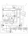
- FIG. 1 is a schematic diagram showing a configuration of a waste heat utilization device 2 for an internal combustion engine according to the present embodiment.
- the waste heat utilization device 2 cools a Rankine cycle circuit 4 and, for example, a vehicle engine (internal combustion engine) 6. And a cooling water circuit 8 through which the cooling water is circulated.
- the Rankine cycle circuit 4 includes an evaporator 10, an exhaust gas heat exchanger (heat exchanger) 12, an expander 14, a condenser 16, a liquid receiver 18, and a pump 20. Circulates in order through the evaporator 10, the exhaust gas heat exchanger 12, the expander 14, the condenser 16, and the liquid receiver 18.
- the evaporator 10 is a heat exchanger that heats the working fluid by exchanging heat mainly between the working fluid delivered from the pump 20 and the high-temperature cooling water flowing through the cooling water circuit 8.
- the evaporator 10 includes a cooling water path for guiding the cooling water and a working fluid path for guiding the working fluid, and the cooling water path and the operation are provided between the cooling water path and the working fluid path.
- a boundary wall that separates the fluid path is provided.
- the exhaust gas heat exchanger 12 is provided in the exhaust gas pipe 22 through which the exhaust gas of the engine 6 flows out, and the working fluid is exchanged between the working fluid heated by the evaporator 10 and the exhaust gas flowing through the exhaust gas pipe 22. Is further heated.
- the expander 14 is a fluid device that generates a driving force related to rotation or the like by the expansion of the working fluid that is heated by the evaporator 10 and the exhaust gas heat exchanger 12 to be in a superheated steam state.
- a generator 24 is connected to the expander 14, and the driving force generated by the expander 14 via the generator 24 can be used outside the waste heat utilization apparatus 2.
- the condenser 16 is a heat exchanger that condenses and liquefies the working fluid discharged from the expander 14 by heat exchange with the outside air.
- the liquid receiver 18 is a receiver that separates the working fluid condensed by the condenser 16 into gas-liquid two layers, and only the separated liquefied working fluid flows out to the pump 20 side, and the pump 20 again.
- the Rankine cycle circuit 4 as a closed circuit is formed by flowing into the evaporator 10 by operation.
- the cooling water circuit 8 includes a radiator 26, a thermostat 28, a linear three-way valve 34, and a pump 30.
- the cooling water exchanges heat with the working fluid of the Rankine cycle circuit 4 in the evaporator 10
- Water is circulated through the engine 6, the linear three-way valve 34, the evaporator 10, the radiator 26, and the thermostat 28 sequentially by the operation of the pump 30.
- the radiator 26 is arranged in series with the evaporator 10 and cools the cooling water circulated by the operation of the pump 30 by exchanging heat with the outside air.
- thermostat 28 Connected to the thermostat 28 is a bypass path 32 that branches from the flow path 8 a of the cooling water circuit 8 between the evaporator 10 and the radiator 26 and bypasses the radiator 26 and merges downstream of the radiator 26.
- the thermostat 28 is a mechanical switching valve that can selectively select whether the cooling water is passed through the radiator 26 or the bypass passage 32 according to the cooling water temperature. 28 switches the flow path according to the cooling water temperature or controls the flow rate of the cooling water flowing to the radiator 26 to keep the body temperature of the engine 6 substantially constant, thereby preventing the engine 6 from overheating.
- the pump 30 is attached to the engine 6 and operates according to the rotational speed of the engine 6 to circulate the amount of cooling water required for cooling the engine 6 to the cooling water circuit 8.
- the linear three-way valve 34 is installed between the engine 6 and the evaporator 10 and has one inlet port and two outlet ports.
- the linear three-way valve 34 is proportional to an input signal input to the drive unit of the three-way valve 34.
- a flow path 8b of a cooling water circuit 8 extending from the engine 6 is connected to the inlet port of the three-way valve 34, and branched to each outlet port from the flow path 8b via the three-way valve 34.
- a bypass path 36 that bypasses the evaporator 10 and joins downstream of the evaporator 10 and a flow path 8 c that extends from the flow path 8 b to the evaporator 10 via the three-way valve 34 are connected.
- the cooling water flowing through the flow path 8b is distributed to the bypass path 36 and the flow path 8c by the three-way valve 34.
- the cooling water flow rate flowing through the flow path 8b is the total flow rate Ft
- the cooling water flow rate flowing through the bypass path 36 is the bypass flow distribution flow rate Fb
- the cooling water flow rate flowing through the flow path 8c is the evaporator distribution flow rate Fe
- the total flow rate Ft bypass.
- the relational expression of the path distribution flow rate Fb + evaporator distribution flow rate Fe is substantially established, and the three-way valve 34 has a structure that does not become a large pressure loss element when viewed from the entirety of the cooling water circuit 8.
- the bypass path 36 is partly shared with the bypass path 32 of the radiator 26, and the cooling water pressure is derived from the shared path 8 d and the flow path 8 c, respectively.
- the differential pressure sensor 38 detects the differential pressure ⁇ P before and after the evaporator 10.
- a temperature sensor 40 for detecting the cooling water temperature T in the bypass passage 32 is provided, a temperature sensor 42 for directly detecting the temperature of the cooling water flowing into the engine 6 and the rotational speed of the engine 6 are detected.
- a rotation speed sensor 44 is attached to the engine 6.
- three-way switching valves (switching valves) 48 and 50 are installed between the exhaust gas heat exchanger 12 and the expander 14, and between the pump 20 and the evaporator 10, respectively. These switching valves 48 and 50 have three ports that can also be used as an inlet port and an outlet port for the working fluid, and each has one valve body corresponding to an input signal input to the drive unit of each switching valve 48 and 50.
- the switching valves 48 and 50 are switched simultaneously and smoothly.
- the switching valves 48 and 50 have a structure that does not become a large pressure loss element when viewed from the whole Rankine cycle circuit 4.
- a flow path 4a extending from the exhaust gas heat exchanger 12 to the switching valve 48, a flow path 4b extending from the expander 14 to the switching valve 48, A flow path 4c (bypass path) extending from the switching valve 50 to the switching valve 48 is connected.
- a flow path 4d extending from the evaporator 10 to the switching valve 50, and a flow path 4e (bypass path) extending from the liquid receiver 18 to the switching valve 50 are provided.
- the flow path 4c is connected.
- a flow path 4f extending from the pump 20 is connected to the flow path 4c, and each of the flow paths 4a to 4f constitutes a part of the Rankine cycle circuit 4.
- the Rankine cycle circuit 4 changes the flow path and the flow direction of the working fluid by switching the switching valves 48 and 50, so that the Rankine cycle path 52 functions as a general Rankine cycle, and the evaporation.
- Both the heat pipe path 54 functioning as a heat pipe for heating the cooling water in the vessel 10 can be formed.
- the Rankine cycle path 52 is switched to form a path 52a in which the switching valve 48 communicates the flow path 4a and the flow path 4b, and the switching valve 50 communicates the flow path 4c and the flow path 4d. It is switched and closed to form the path 52b.
- FIG. 1 shows a state in which the Rankine cycle path 52 is formed.
- the white ports of the switching valves 48 and 50 indicate fully open ports, and the black ports indicate fully closed ports. That is, the Rankine cycle path 52 includes the expander 14, the condenser 16, and the constituent elements of the Rankine cycle circuit 4 other than the evaporator 10 and the exhaust gas heat exchanger 12 (heat exchange region), the liquid receiver 18, and the pump 20.
- a unit (energy generation region) 56 including the generator 24 is included.
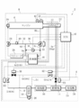
- FIG. 2 shows a state in which the heat pipe path 54 is formed.
- the switching valve 48 is switched to form a path 54a in which the flow path 4a and the flow path 4c are communicated.
- the switching valve 50 is switched and closed to form a path 54b formed by communicating the flow path 4d and the flow path 4e.
- the white ports of the switching valves 48 and 50 in FIG. 2 indicate fully open ports, and the black ports indicate fully closed ports. That is, the heat pipe path 54 is configured to bypass the unit 56, and the working fluid heated by the exhaust gas heat exchanger 12 heats the cooling water circulating in the cooling water circuit 8 in the evaporator 10.
- the Rankine cycle circuit 4 constitutes the heat pipe path 54 that functions as a heat pipe in which the working fluid heated and evaporated by the exhaust gas heat exchanger 12 using the pump 20 as a drive source radiates and condenses and circulates in the evaporator.
- the working fluid circulating in the heat pipe path 54 flows in a direction opposite to the flow direction of the working fluid in the Rankine cycle path 52, and the flow direction of the cooling water and the working fluid exchanged in the evaporator 10 is determined by the Rankine cycle.
- the flow direction is opposite, whereas in the heat pipe path 54, the flow direction is the same.
- control of each sensor and the motor-operated valve will be described.
- the sensors 38, 40, 42, 44 serving as detection ends, the three-way valve 34 serving as the operation end, and the switching valves 48, 50 are electrically connected to an electronic control unit (ECU) 46 that performs overall control of the vehicle and the waste heat utilization device 2.
- ECU electronice control unit
- the ECU 46 outputs a signal to drive and control a desired outlet port of the three-way valve 34 to a desired opening based on an input signal detected from the differential pressure sensor 38, and detects from the temperature sensor 40. Based on the input signal, a signal is output so as to switch the desired ports of the switching valves 48 and 50 to fully open or fully closed simultaneously.
- the ECU 46 executes a control routine that controls the differential pressure valve opening degree that drives the three-way valve 34 in accordance with the differential pressure ⁇ P before and after the evaporator 10 detected by the differential pressure sensor 38. That is, by driving the three-way valve 34 so that the differential pressure ⁇ P is equal to or less than a predetermined differential pressure set value ⁇ PH preset by the ECU 46, even if the total flow rate Ft of the cooling water fluctuates, the fluctuation amount is evaporated. By flowing to the bypass path 36 without flowing to 10, the evaporator distribution flow rate Fe can be limited to substantially constant or less.
- the ECU 46 executes a control routine which is a temperature valve switching control (flow path switching means) for simultaneously switching and driving the switching valves 48 and 50 in accordance with the coolant temperature T detected by the temperature sensor 40. It is processed in the ECU 46 as a control routine independent of the pressure valve opening control.
- a control routine which is a temperature valve switching control (flow path switching means) for simultaneously switching and driving the switching valves 48 and 50 in accordance with the coolant temperature T detected by the temperature sensor 40. It is processed in the ECU 46 as a control routine independent of the pressure valve opening control.
- S represents a step
- the process proceeds to S1.
- S1 it is determined whether or not the coolant temperature T detected by the temperature sensor 40 is equal to or lower than a predetermined temperature set value TL . If the determination result is true (Yes) and the cooling water temperature T is determined to be equal to or lower than the predetermined temperature setting value TL , the process proceeds to S3, and the determination result is false (No) and the cooling water temperature T is the temperature setting value T. If it is determined that it is greater than L, the process proceeds to S2.
- the switching valves 48 and 50 are simultaneously switched to form the Rankine cycle path 52.
- the switching state of the switching valves 48 and 50 is maintained as it is.
- the switching valves 48 and 50 are simultaneously switched to form the heat pipe path 54.
- the heat pipe path 54 is already formed, the switching state of the switching valves 48 and 50 is maintained as it is. In this manner, when the temperature valve switching control is started in S0, a series of control routines of S1 and S2 or S1 and S3 are repeatedly executed.
- the Rankine cycle circuit 4 bypasses the unit 56 including the expander 14, the condenser 16, and the generator 24, so that the evaporator 10, the exhaust gas heat exchanger 12, and the liquid receiver are bypassed. 18.
- a heat pipe path 54 which is composed of only the pump 20 and is a so-called heat exchange region, is formed.
- the heat pipe path 54 causes the working fluid heated by the exhaust gas heat exchanger 12 to flow into the evaporator 10 and heats the cooling water in the cooling water circuit 8. That is, the Rankine cycle circuit 4 can function as a normal Rankine cycle and also function as a heat pipe that heats the cooling water.
- the heat of the exhaust gas heat exchanger 12 in the Rankine cycle circuit 4 can be positively introduced into the evaporator 10.
- the heat pipe path 54 of the Rankine cycle circuit 4 when the temperature T of the cooling water detected by the temperature sensor 40 is below a predetermined temperature set point T L is the switching Setsu ⁇ 48 in order to bypass the unit 56 It is done.
- This not only stops the function of the Rankine cycle circuit 4 and prevents the engine 6 from being overcooled by the cooling water, particularly when starting the engine 6 in which the cooling water temperature T is lowered.
- the engine 6 can be quickly warmed up with the cooled cooling water, and the deterioration of fuel consumption when the engine 6 is started is greatly improved. Therefore, the functions of both the coolant circuit 8 and the Rankine cycle circuit 4 can be made to function properly only in an appropriate environment at an appropriate time according to the operating state of the engine 6.
- the temperature sensor 40 is installed as the detection end.
- the temperature sensor 42 attached to the engine 6 is used. Even when used, the same effects as those of the above-described embodiment can be obtained.
- the switching valves 48 and 50 are operated based on the cooling water temperature to form the heat pipe path to heat the cooling water.
- the engine 6 is mainly warmed up when the engine 6 is started.
- the switching valves 48 and 50 are switched for a predetermined time from the start of the engine 6 to form the heat pipe path, the same effect as in the above embodiment can be obtained.
- the switching valves 48 and 50 that are three-way switching valves are used.
- a heat pipe path 56 may be formed.
- the solenoid valves 58 and 60 and the switching valve 50 may be used in place of the solenoid valves 62 and 64 in the same manner.
Landscapes
- Engineering & Computer Science (AREA)
- Chemical & Material Sciences (AREA)
- Combustion & Propulsion (AREA)
- Mechanical Engineering (AREA)
- General Engineering & Computer Science (AREA)
- Life Sciences & Earth Sciences (AREA)
- Atmospheric Sciences (AREA)
- Engine Equipment That Uses Special Cycles (AREA)
Abstract
内燃機関(6)の廃熱利用装置(2)は、冷却水を冷却するラジエータ(26)を有する冷却水回路(8)と、蒸発器(8)及び熱交換器(12)で熱交換領域を形成するとともに、膨張機(14)と凝縮器(16)でエネルギ発生領域(56)を形成するランキンサイクル回路(4)とを備え、ランキンサイクル回路(4)は、エネルギ発生領域(56)をバイパスするバイパス路(4c,4e)と、該バイパス路(4c,4e)に切り換えることにより、熱交換器(12)で加熱された作動流体を蒸発器(8)に流入させ、作動流体で冷却水を加熱するヒートパイプ経路(54)を形成する流路切換手段とを有する。
Description
本発明は、内燃機関の廃熱利用装置に係り、詳しくは、車両に好適な内燃機関の廃熱利用装置に関する。
内燃機関の廃熱利用装置としては、例えば車両用内燃機関において、冷凍サイクルの構成部品を利用してランキンサイクル回路を形成することで内燃機関の廃熱を動力回収し、その回収した動力で内燃機関の軸出力をアシストする技術が知られている(日本国特許第2540738号公報参照)。
この技術によると、冷凍サイクル回路はコンプレッサと蒸発器とを含んで構成されており、このコンプレッサは、内燃機関を駆動源とする圧縮機、及び内燃機関をアシストする膨張機として使用されている。また、この蒸発器は、内燃機関の冷却水回路に組み込まれた高温蒸発器と選択的に切り換えられるように構成され、この高温蒸発器を蒸発器に換えて冷凍サイクル回路に接続することでランキンサイクル回路が形成される。
しかしながら、上記従来技術のランキンサイクル回路では、内燃機関の暖機に排ガスの熱を利用する点については格別な配慮がなされていない。
この技術によると、冷凍サイクル回路はコンプレッサと蒸発器とを含んで構成されており、このコンプレッサは、内燃機関を駆動源とする圧縮機、及び内燃機関をアシストする膨張機として使用されている。また、この蒸発器は、内燃機関の冷却水回路に組み込まれた高温蒸発器と選択的に切り換えられるように構成され、この高温蒸発器を蒸発器に換えて冷凍サイクル回路に接続することでランキンサイクル回路が形成される。
しかしながら、上記従来技術のランキンサイクル回路では、内燃機関の暖機に排ガスの熱を利用する点については格別な配慮がなされていない。
本発明は、このような課題に鑑みてなされたもので、内燃機関の作動状況に応じて内燃機関の冷却水加熱回路とランキンサイクル回路との両方を適正に機能させることができる内燃機関の廃熱利用装置を提供することを目的とする。
上記の目的を達成するべく、本発明の内燃機関の廃熱利用装置は、冷却水により冷却される内燃機関と、冷却水を冷却するラジエータを有し、該ラジエータで冷却された冷却水が内燃機関を経由して循環する冷却水回路と、内燃機関を経由した冷却水と熱交換して作動流体を加熱する蒸発器、該蒸発器を経由した作動流体を熱媒体と熱交換して更に加熱する熱交換器、該熱交換器を経由した作動流体を膨張させて駆動力を発生する膨張機、該膨張機を経由した作動流体を凝縮させる凝縮器を有し、蒸発器及び熱交換器で熱交換領域を形成するとともに、膨張機と凝縮器でエネルギ発生領域を形成し、該エネルギ発生領域と該熱交換領域との間で作動流体を循環させるポンプを更に含むランキンサイクル回路とを備え、ランキンサイクル回路は、エネルギ発生領域をバイパスするバイパス路と、該バイパス路に切り換えることにより、熱交換器で加熱蒸発された作動流体を蒸発器に流入させ、凝縮する作動流体で冷却水を加熱し、ポンプで再び熱交換器に作動流体を循環させるヒートパイプとして機能させるヒートパイプ経路を形成する流路切換手段とを有することを特徴としている。
上記の目的を達成するべく、本発明の内燃機関の廃熱利用装置は、冷却水により冷却される内燃機関と、冷却水を冷却するラジエータを有し、該ラジエータで冷却された冷却水が内燃機関を経由して循環する冷却水回路と、内燃機関を経由した冷却水と熱交換して作動流体を加熱する蒸発器、該蒸発器を経由した作動流体を熱媒体と熱交換して更に加熱する熱交換器、該熱交換器を経由した作動流体を膨張させて駆動力を発生する膨張機、該膨張機を経由した作動流体を凝縮させる凝縮器を有し、蒸発器及び熱交換器で熱交換領域を形成するとともに、膨張機と凝縮器でエネルギ発生領域を形成し、該エネルギ発生領域と該熱交換領域との間で作動流体を循環させるポンプを更に含むランキンサイクル回路とを備え、ランキンサイクル回路は、エネルギ発生領域をバイパスするバイパス路と、該バイパス路に切り換えることにより、熱交換器で加熱蒸発された作動流体を蒸発器に流入させ、凝縮する作動流体で冷却水を加熱し、ポンプで再び熱交換器に作動流体を循環させるヒートパイプとして機能させるヒートパイプ経路を形成する流路切換手段とを有することを特徴としている。
上記した内燃機関の廃熱利用装置によれば、ランキンサイクル回路は、通常のランキンサイクルとして機能するとともに、冷却水を加熱するヒートパイプとしても機能させることができる。従って、排ガスの熱を蒸発器に積極的に導入することが可能となる。
好適な態様として、上記した内燃機関の廃熱利用装置において、流路切換手段は、冷却水回路を循環する冷却水の温度を検出する温度センサと、該温度センサで検出された冷却水の温度が所定の温度以下のときには、バイパス路に切り換えてヒートパイプ経路を形成する切換弁と含む。
この構成によれば、特に内燃機関の始動時には、排ガスの熱が冷却水に導入されるため、その暖機が迅速に且つ確実に実施され、内燃機関の作動状況に応じた冷却水回路及びランキンサイクル回路の両方の機能の適正化を迅速に図ることができる。
好適な態様として、上記した内燃機関の廃熱利用装置において、流路切換手段は、冷却水回路を循環する冷却水の温度を検出する温度センサと、該温度センサで検出された冷却水の温度が所定の温度以下のときには、バイパス路に切り換えてヒートパイプ経路を形成する切換弁と含む。
この構成によれば、特に内燃機関の始動時には、排ガスの熱が冷却水に導入されるため、その暖機が迅速に且つ確実に実施され、内燃機関の作動状況に応じた冷却水回路及びランキンサイクル回路の両方の機能の適正化を迅速に図ることができる。
以下、図面により本発明の一実施形態について説明する。
図1は本実施形態の内燃機関の廃熱利用装置2の構成を示す模式図であって、この廃熱利用装置2は、ランキンサイクル回路4と、例えば車両のエンジン(内燃機関)6を冷却する冷却水が循環する冷却水回路8とを含んで構成されている。
ランキンサイクル回路4は、蒸発器10、排ガス熱交換器(熱交換器)12、膨張機14、凝縮器16、受液器18、及びポンプ20を含んで構成され、ポンプ20の作動によって作動流体が蒸発器10、排ガス熱交換器12、膨張機14、凝縮器16、受液器18を順次流れて循環する。
蒸発器10は、主としてポンプ20から送出される作動流体と冷却水回路8を流通する高温の冷却水との間で熱交換することにより作動流体を加熱する熱交換器である。蒸発器10内には、いずれも図示しないが、冷却水を導く冷却水経路と、作動流体を導く作動流体経路とを備え、冷却水経路と作動流体経路との間には冷却水経路と作動流体経路とを区画する境界壁が設けられている。
排ガス熱交換器12は、エンジン6の排ガスが流出される排ガス管22内に設けられ、蒸発器10で加熱された作動流体と排ガス管22を流れる排ガスとの間で熱交換することにより作動流体が更に加熱される。
膨張機14は、蒸発器10、及び排ガス熱交換器12で加熱され過熱蒸気の状態となる作動流体の膨張によって回転等に係る駆動力を発生させる流体機器である。また、膨張機14には例えば発電機24が接続され、発電機24を介して膨張機14で発生した駆動力を廃熱利用装置2の外部で使用可能である。
凝縮器16は、膨張機14から吐出される作動流体を外気との熱交換によって凝縮液化する熱交換器である。また、受液器18は、凝縮器16で凝縮された作動流体を気液二層に分離するレシーバであり、ここで分離された液化作動流体のみがポンプ20側に流出され、再びポンプ20の作動によって蒸発器10に流入することにより閉回路としてのランキンサイクル回路4が形成される。
一方、冷却水回路8は、ラジエータ26、サーモスタット28、リニア三方弁34、ポンプ30を含んで構成され、冷却水が蒸発器10においてランキンサイクル回路4の作動流体と熱交換する際には、冷却水がポンプ30の作動によってエンジン6、リニア三方弁34、蒸発器10、ラジエータ26、サーモスタット28を順次流れて循環する。
ラジエータ26は、蒸発器10と直列に配列され、ポンプ30の作動によって循環される冷却水を外気との熱交換により冷却する。
サーモスタット28には、蒸発器10とラジエータ26との間における冷却水回路8の流路8aから分岐するとともにラジエータ26を迂回してラジエータ26の下流に合流するバイパス路32が接続されている。これより、サーモスタット28は、冷却水をその冷却水温度に応じてラジエータ26へ通水させるかバイパス路32へ通水させるかを択一的に選択可能な機械式の切換弁であって、サーモスタット28が冷却水温度に応じて流路を切り換え或いはラジエータ26へ通水する冷却水の流量を配分制御することによりエンジン6の本体温度を略一定に保持し、エンジン6の過熱が防止される。
ポンプ30は、エンジン6に装着され、エンジン6の回転数に応じて作動することによりエンジン6の冷却に要する冷却水量を冷却水回路8に循環させる。
リニア三方弁34は、エンジン6と蒸発器10との間に設置され、1つの入口ポートと2つの出口ポートとを有し、三方弁34の駆動部に入力される入力信号に比例して1つの弁体を連続的に可変駆動することにより、入口ポートに流入する冷却水を各出口ポートに配分して流出させるとともに、これら各配分流量を微調整可能な電動弁である。
詳しくは、三方弁34の入口ポートには、エンジン6から延設される冷却水回路8の流路8bが接続され、各出口ポートには、流路8bから三方弁34を介して分岐されるとともに蒸発器10を迂回して蒸発器10の下流に合流するバイパス路36、流路8bから三方弁34を介して蒸発器10まで延設される流路8cがそれぞれ接続されている。
これより、流路8bを流れる冷却水は、三方弁34によってバイパス路36と流路8cとに配分される。流路8bを流れる冷却水流量を全流量Ft、バイパス路36を流れる冷却水流量をバイパス路配分流量Fb、流路8cを流れる冷却水流量を蒸発器配分流量Feとすると、全流量Ft=バイパス路配分流量Fb+蒸発器配分流量Feの関係式が略成立し、三方弁34は冷却水回路8の全体からみて大きな圧力損失要素とはならない構造となっている。
一方、バイパス路36はラジエータ26のバイパス路32と一部が共用されており、この共用路8dと流路8cとからはそれぞれ冷却水圧力が導出され、これら導出された圧力は差圧センサ38に入力されている。すなわち、差圧センサ38は蒸発器10の前後における差圧ΔPを検出している。
一方、バイパス路36はラジエータ26のバイパス路32と一部が共用されており、この共用路8dと流路8cとからはそれぞれ冷却水圧力が導出され、これら導出された圧力は差圧センサ38に入力されている。すなわち、差圧センサ38は蒸発器10の前後における差圧ΔPを検出している。
他のセンサとしては、バイパス路32における冷却水温度Tを検出する温度センサ40が設けられる他、エンジン6に流入する冷却水の温度を直接検出する温度センサ42やエンジン6の回転数を検出する回転数センサ44がエンジン6に装着されている。
ところで、ランキンサイクル回路4において、排ガス熱交換器12と膨張機14との間、及びポンプ20と蒸発器10との間にはそれぞれ三方切換弁(切換弁)48,50が設置されている。
これら切換弁48,50は、作動流体の入口ポート及び出口ポートとして兼用可能な3つのポートを有し、各切換弁48,50の駆動部に入力される入力信号に応じてそれぞれ1つの弁体を駆動するとともに、作動流体の流れ方向に拘らず、それぞれ異なる2つの流路のいずれか一方を択一的に選択して切換可能な電動式の切換弁である。なお、切換弁48,50の切換は同時に且つ円滑になされ、切換弁48,50は三方弁34と同様にランキンサイクル回路4の全体からみて大きな圧力損失要素とはならない構造となっている。
詳しくは、切換弁48の各ポートには、排ガス熱交換器12から切換弁48に亘って延設される流路4a、膨張機14から切換弁48に亘って延設される流路4b、切換弁50から切換弁48に亘って延設される流路4c(バイパス路)が接続されている。
一方、切換弁50の各ポートには、蒸発器10から切換弁50に亘って延設される流路4d、受液器18から切換弁50に亘って延設される流路4e(バイパス路)、並びに上記流路4cが接続されている。また、流路4cにはポンプ20から延設される流路4fが接続され、これら各流路4a~4fはランキンサイクル回路4の一部を構成している。
ここで、本実施形態のランキンサイクル回路4は、切換弁48,50の切換によって作動流体の流路及び流れ方向を変更することにより、一般的なランキンサイクルとして機能するランキンサイクル経路52と、蒸発器10において冷却水を加熱するヒートパイプとして機能するヒートパイプ経路54との両方を形成できる。
詳しくは、ランキンサイクル経路52は、切換弁48が流路4aと流路4bとを連通させてなる経路52aを形成すべく切り換えられるとともに、切換弁50が流路4cと流路4dとを連通させてなる経路52bを形成すべく切り換えられて閉成される。なお、図1はランキンサイクル経路52が形成された状態を示しており、切換弁48,50の白抜きされたポートは全開ポートを示し、黒塗りされたポートは全閉ポートを示している。
すなわち、ランキンサイクル経路52は、蒸発器10及び排ガス熱交換器12(熱交換領域)、並びに受液器18、ポンプ20以外のランキンサイクル回路4の構成要素である膨張機14、凝縮器16、発電機24からなるユニット(エネルギ発生領域)56を含んで構成されている。
すなわち、ランキンサイクル経路52は、蒸発器10及び排ガス熱交換器12(熱交換領域)、並びに受液器18、ポンプ20以外のランキンサイクル回路4の構成要素である膨張機14、凝縮器16、発電機24からなるユニット(エネルギ発生領域)56を含んで構成されている。
一方、図2にはヒートパイプ経路54が形成された状態が示されており、この場合には、切換弁48が流路4aと流路4cとを連通させてなる経路54aを形成すべく切り換えられるとともに、切換弁50が流路4dと流路4eとを連通させてなる経路54bを形成すべく切り換えられて閉成される。なお、図1と同様に、図2中の切換弁48,50の白抜きされたポートは全開ポートを示し、黒塗りされたポートは全閉ポートを示している。
すなわち、ヒートパイプ経路54は、上記ユニット56をバイパスして構成されており、排ガス熱交換器12で加熱された作動流体が蒸発器10において冷却水回路8を循環する冷却水を加熱する。蒸発器10で冷却水を加熱した後の作動流体は、切換弁50、受液器18、ポンプ20、切換弁48を順次経由し、再び排ガス熱交換器12に到達する。
このように、ランキンサイクル回路4は、ポンプ20を駆動源として排ガス熱交換器12で加熱蒸発された作動流体が蒸発器で放熱凝縮し循環するヒートパイプとして機能するヒートパイプ経路54を構成する。
すなわち、ヒートパイプ経路54は、上記ユニット56をバイパスして構成されており、排ガス熱交換器12で加熱された作動流体が蒸発器10において冷却水回路8を循環する冷却水を加熱する。蒸発器10で冷却水を加熱した後の作動流体は、切換弁50、受液器18、ポンプ20、切換弁48を順次経由し、再び排ガス熱交換器12に到達する。
このように、ランキンサイクル回路4は、ポンプ20を駆動源として排ガス熱交換器12で加熱蒸発された作動流体が蒸発器で放熱凝縮し循環するヒートパイプとして機能するヒートパイプ経路54を構成する。
なお、ヒートパイプ経路54を循環する作動流体は、ランキンサイクル経路52における作動流体の流れ方向と逆方向に流れ、蒸発器10で熱交換される冷却水と作動流体との流れ方向は、ランキンサイクル経路52では対向する流れ方向であるのに対し、ヒートパイプ経路54では同一の流れ方向となる。
以下、上記した各センサ及び電動弁の制御について説明する。
検出端たる各センサ38,40,42,44及び操作端たる三方弁34、切換弁48,50は車両及び廃熱利用装置2の総合的な制御を行う電子コントロールユニット(ECU)46に電気的に接続されており、ECU46は、差圧センサ38から検出される入力信号に基づいて三方弁34の所望の出口ポートを所望の開度に駆動制御すべく信号を出力し、温度センサ40から検出される入力信号に基づいて切換弁48,50の所望のポートを全開または全閉に同時に切換駆動すべく信号を出力する。
以下、上記した各センサ及び電動弁の制御について説明する。
検出端たる各センサ38,40,42,44及び操作端たる三方弁34、切換弁48,50は車両及び廃熱利用装置2の総合的な制御を行う電子コントロールユニット(ECU)46に電気的に接続されており、ECU46は、差圧センサ38から検出される入力信号に基づいて三方弁34の所望の出口ポートを所望の開度に駆動制御すべく信号を出力し、温度センサ40から検出される入力信号に基づいて切換弁48,50の所望のポートを全開または全閉に同時に切換駆動すべく信号を出力する。
詳しくは、ECU46では、差圧センサ38で検出される蒸発器10の前後の差圧ΔPに応じて三方弁34を駆動する差圧バルブ開度制御たる制御ルーチンが実行される。すなわち、差圧ΔPがECU46で予め設定された所定の差圧設定値ΔPH以下となるように三方弁34を駆動することにより、冷却水の全流量Ftが変動してもその変動分を蒸発器10へ流さずにバイパス路36に流すことにより、蒸発器配分流量Feを略一定或いはそれ以下に制限することができる。
同じくECU46では、温度センサ40で検出される冷却水温度Tに応じて切換弁48,50を同時に切換駆動する温度バルブ切換制御(流路切換手段)たる制御ルーチンが実行され、この制御ルーチンは差圧バルブ開度制御とは独立した制御ルーチンとしてECU46内で処理されている。
同じくECU46では、温度センサ40で検出される冷却水温度Tに応じて切換弁48,50を同時に切換駆動する温度バルブ切換制御(流路切換手段)たる制御ルーチンが実行され、この制御ルーチンは差圧バルブ開度制御とは独立した制御ルーチンとしてECU46内で処理されている。
以下、図3に示されるフローチャートを参照して温度バルブ切換制御について説明する。
先ず、S0(以下、Sはステップを表す)で温度バルブ切換制御が開始されると、S1に移行する。
S1では、温度センサ40で検出された冷却水温度Tが所定の温度設定値TL以下であるか否かを判別する。判別結果が真(Yes)で冷却水温度Tが所定の温度設定値TL以下と判定された場合にはS3に移行し、判別結果が偽(No)で冷却水温度Tが温度設定値TLより大きいと判定された場合にはS2に移行する。
S2に移行した場合には、ランキンサイクル経路52を形成すべく切換弁48,50が同時に切り換えられる。既にランキンサイクル経路52が形成されている場合には、切換弁48,50の切換状態はそのまま保持される。
一方、S1においてS3に移行した場合には、ヒートパイプ経路54を形成すべく切換弁48,50が同時に切り換えられる。既にヒートパイプ経路54が形成されている場合には、切換弁48,50の切換状態はそのまま保持される。
このようにして、S0において温度バルブ切換制御が開始されると、S1及びS2、またはS1及びS3の一連の制御ルーチンが繰り返し実行される。
以上のように、本実施形態では、ランキンサイクル回路4は、膨張機14、凝縮器16、発電機24を含むユニット56をバイパスすることにより、蒸発器10、排ガス熱交換器12、受液器18、ポンプ20のみからなる、いわば熱交換領域たるヒートパイプ経路54を形成する。このヒートパイプ経路54は、排ガス熱交換器12で加熱された作動流体を蒸発器10に流入させて冷却水回路8の冷却水を加熱する。すなわち、ランキンサイクル回路4は、通常のランキンサイクルとして機能するとともに、冷却水を加熱するヒートパイプとしても機能させることができる。
これにより、ランキンサイクル回路4における排ガス熱交換器12の熱を蒸発器10に積極的に導入することが可能となる。
また、ランキンサイクル回路4のヒートパイプ経路54は、温度センサ40で検出された冷却水の温度Tが所定の温度設定値TL以下のときには、ユニット56をバイパスすべく切換弁48,50が切り換えられる。これにより、特に、冷却水温度Tが低下しているエンジン6の始動時には、ランキンサイクル回路4の機能を停止してエンジン6が冷却水で過冷却されることが防止されるのみならず、加熱された冷却水でエンジン6を迅速に暖機させることができ、エンジン6の始動時における燃費の悪化が大幅に改善される。従って、エンジン6の作動状況に応じて冷却水回路8及びランキンサイクル回路4の両方の機能を適切な時期に適切な環境でのみ適正に機能させることができる。
以上で本発明の一実施形態についての説明を終えるが、本発明は上記実施形態に限定されるものではなく、本発明の趣旨を逸脱しない範囲で種々の変更ができるものである。
例えば、上記実施形態では、検出端として温度センサ40を設置しているが、冷却水回路8を循環する冷却水温度が測定可能であれば良く、代わりにエンジン6に装着される温度センサ42を使用する場合にも上記実施形態と同様の効果を奏する。
また、上記実施形態では、冷却水温度に基づいて切換弁48,50を作動させ、ヒートパイプ経路を形成することにより冷却水を加熱しているが、主にエンジン6の始動時の暖機が迅速に実施されれば良く、例えばエンジン6の始動から所定の時間だけ切換弁48,50を切り換えてヒートパイプ経路を形成するようにしても上記実施形態と同様の効果が得られる。
更に、上記実施形態では、三方切換弁たる切換弁48,50を使用しているが、ヒートパイプ経路56が形成されれば良く、例えば図4、5に示されるように切換弁48の代わりに電磁弁58,60、切換弁50の代わりに電磁弁62,64を使用して同様に制御しても良い。
Claims (2)
- 内燃機関の廃熱利用装置であって、
冷却水により冷却される内燃機関と、
前記冷却水を冷却するラジエータを有し、該ラジエータで冷却された冷却水が前記内燃機関を経由して循環する冷却水回路と、
前記内燃機関を経由した冷却水と熱交換して作動流体を加熱する蒸発器、該蒸発器を経由した作動流体を熱媒体と熱交換して更に加熱する熱交換器、該熱交換器を経由した作動流体を膨張させて駆動力を発生する膨張機、該膨張機を経由した作動流体を凝縮させる凝縮器を有し、前記蒸発器及び前記熱交換器で熱交換領域を形成するとともに、前記膨張機と前記凝縮器でエネルギ発生領域を形成し、該エネルギ発生領域と該熱交換領域との間で作動流体を循環させるポンプを更に含むランキンサイクル回路とを備え、
前記ランキンサイクル回路は、前記エネルギ発生領域をバイパスするバイパス路と、該バイパス路に切り換えることにより、前記熱交換器で加熱蒸発された作動流体を前記蒸発器に流入させ、凝縮する作動流体で冷却水を加熱し、前記ポンプで再び前記熱交換器に作動流体を循環させるヒートパイプとして機能させるヒートパイプ経路を形成する流路切換手段とを有する。 - 請求項1の内燃機関の廃熱利用装置であって、
前記流路切換手段は、前記冷却水回路を循環する冷却水の温度を検出する温度センサと、該温度センサで検出された冷却水の温度が所定の温度以下のときには、前記バイパス路に切り換えて前記ヒートパイプ経路を形成する切換弁と含む。
Priority Applications (1)
| Application Number | Priority Date | Filing Date | Title |
|---|---|---|---|
| PCT/JP2008/058383 WO2009133619A1 (ja) | 2008-05-01 | 2008-05-01 | 内燃機関の廃熱利用装置 |
Applications Claiming Priority (1)
| Application Number | Priority Date | Filing Date | Title |
|---|---|---|---|
| PCT/JP2008/058383 WO2009133619A1 (ja) | 2008-05-01 | 2008-05-01 | 内燃機関の廃熱利用装置 |
Publications (1)
| Publication Number | Publication Date |
|---|---|
| WO2009133619A1 true WO2009133619A1 (ja) | 2009-11-05 |
Family
ID=41254849
Family Applications (1)
| Application Number | Title | Priority Date | Filing Date |
|---|---|---|---|
| PCT/JP2008/058383 WO2009133619A1 (ja) | 2008-05-01 | 2008-05-01 | 内燃機関の廃熱利用装置 |
Country Status (1)
| Country | Link |
|---|---|
| WO (1) | WO2009133619A1 (ja) |
Cited By (6)
| Publication number | Priority date | Publication date | Assignee | Title |
|---|---|---|---|---|
| WO2011122294A1 (ja) * | 2010-03-29 | 2011-10-06 | 株式会社豊田自動織機 | 廃熱回生システム |
| WO2012110893A1 (en) * | 2011-02-17 | 2012-08-23 | Toyota Jidosha Kabushiki Kaisha | Abnormality detection apparatus and abnormality detection method for rankine cycle system |
| CN102713167A (zh) * | 2010-01-21 | 2012-10-03 | 三菱重工业株式会社 | 废热回收发电装置及具备该装置的船舶 |
| US20140224469A1 (en) * | 2013-02-11 | 2014-08-14 | Access Energy Llc | Controlling heat source fluid for thermal cycles |
| US20150089943A1 (en) * | 2013-10-02 | 2015-04-02 | Ford Global Technologies, Llc | Methods and systems for hybrid vehicle waste heat recovery |
| US9551487B2 (en) | 2012-03-06 | 2017-01-24 | Access Energy Llc | Heat recovery using radiant heat |
Citations (6)
| Publication number | Priority date | Publication date | Assignee | Title |
|---|---|---|---|---|
| JPS63289203A (ja) * | 1987-05-20 | 1988-11-25 | Mazda Motor Corp | エンジンの廃熱エネルギ−回収装置 |
| JP2005155336A (ja) * | 2003-11-20 | 2005-06-16 | Denso Corp | ランキンサイクルおよび熱サイクル |
| JP2005180711A (ja) * | 2003-01-27 | 2005-07-07 | Denso Corp | 蒸気圧縮式冷凍機 |
| JP2005273452A (ja) * | 2003-05-20 | 2005-10-06 | Denso Corp | 流体機械 |
| JP2006169970A (ja) * | 2004-12-13 | 2006-06-29 | Sanden Corp | ランキンシステム |
| JP2006242174A (ja) * | 2005-02-02 | 2006-09-14 | Toyota Industries Corp | 車両用排熱回収システム |
-
2008
- 2008-05-01 WO PCT/JP2008/058383 patent/WO2009133619A1/ja active Application Filing
Patent Citations (6)
| Publication number | Priority date | Publication date | Assignee | Title |
|---|---|---|---|---|
| JPS63289203A (ja) * | 1987-05-20 | 1988-11-25 | Mazda Motor Corp | エンジンの廃熱エネルギ−回収装置 |
| JP2005180711A (ja) * | 2003-01-27 | 2005-07-07 | Denso Corp | 蒸気圧縮式冷凍機 |
| JP2005273452A (ja) * | 2003-05-20 | 2005-10-06 | Denso Corp | 流体機械 |
| JP2005155336A (ja) * | 2003-11-20 | 2005-06-16 | Denso Corp | ランキンサイクルおよび熱サイクル |
| JP2006169970A (ja) * | 2004-12-13 | 2006-06-29 | Sanden Corp | ランキンシステム |
| JP2006242174A (ja) * | 2005-02-02 | 2006-09-14 | Toyota Industries Corp | 車両用排熱回収システム |
Cited By (10)
| Publication number | Priority date | Publication date | Assignee | Title |
|---|---|---|---|---|
| CN102713167A (zh) * | 2010-01-21 | 2012-10-03 | 三菱重工业株式会社 | 废热回收发电装置及具备该装置的船舶 |
| WO2011122294A1 (ja) * | 2010-03-29 | 2011-10-06 | 株式会社豊田自動織機 | 廃熱回生システム |
| JP5333659B2 (ja) * | 2010-03-29 | 2013-11-06 | 株式会社豊田自動織機 | 廃熱回生システム |
| WO2012110893A1 (en) * | 2011-02-17 | 2012-08-23 | Toyota Jidosha Kabushiki Kaisha | Abnormality detection apparatus and abnormality detection method for rankine cycle system |
| CN103370521A (zh) * | 2011-02-17 | 2013-10-23 | 丰田自动车株式会社 | 用于朗肯循环系统的异常检测装置和异常检测方法 |
| CN103370521B (zh) * | 2011-02-17 | 2014-10-29 | 丰田自动车株式会社 | 用于朗肯循环系统的异常检测装置和异常检测方法 |
| US9551487B2 (en) | 2012-03-06 | 2017-01-24 | Access Energy Llc | Heat recovery using radiant heat |
| US20140224469A1 (en) * | 2013-02-11 | 2014-08-14 | Access Energy Llc | Controlling heat source fluid for thermal cycles |
| US20150089943A1 (en) * | 2013-10-02 | 2015-04-02 | Ford Global Technologies, Llc | Methods and systems for hybrid vehicle waste heat recovery |
| US9587546B2 (en) * | 2013-10-02 | 2017-03-07 | Ford Global Technologies, Llc | Methods and systems for hybrid vehicle waste heat recovery |
Similar Documents
| Publication | Publication Date | Title |
|---|---|---|
| JP5018592B2 (ja) | 廃熱回収装置 | |
| JP5008441B2 (ja) | 内燃機関の廃熱利用装置 | |
| EP2284458A1 (en) | Waste heat utilization device for internal combustion | |
| JP5338731B2 (ja) | 廃熱回生システム | |
| JP5338730B2 (ja) | 廃熱回生システム | |
| JP5281587B2 (ja) | 内燃機関の廃熱利用装置 | |
| JP4135626B2 (ja) | 発熱体の廃熱利用装置 | |
| JP4089619B2 (ja) | ランキンサイクルシステム | |
| JP2008231980A (ja) | 内燃機関の廃熱利用装置 | |
| KR20110041393A (ko) | 폐열 회생 시스템 | |
| WO2009133619A1 (ja) | 内燃機関の廃熱利用装置 | |
| KR20110041392A (ko) | 폐열 회생 시스템 | |
| JP2009133266A (ja) | 内燃機関の廃熱利用装置 | |
| US10041380B2 (en) | Engine preheating apparatus and preheating method of the engine | |
| JP2008133728A (ja) | 内燃機関の廃熱利用装置 | |
| CN106414982B (zh) | 发动机的废热利用装置 | |
| WO2012039225A1 (ja) | ランキンサイクル装置 | |
| US9988945B2 (en) | Apparatus for utilizing heat wasted from engine | |
| JP2008145022A (ja) | 廃熱利用装置を備える冷凍装置 | |
| JP4140543B2 (ja) | 廃熱利用装置 | |
| JP5084233B2 (ja) | 内燃機関の廃熱利用装置 | |
| WO2016056611A1 (ja) | 廃熱回収装置 | |
| JP2008184906A (ja) | 内燃機関の廃熱利用装置 | |
| JP2008196342A (ja) | 内燃機関の廃熱利用装置 | |
| JP7059971B2 (ja) | 電池冷却システム |
Legal Events
| Date | Code | Title | Description |
|---|---|---|---|
| 121 | Ep: the epo has been informed by wipo that ep was designated in this application |
Ref document number: 08752290 Country of ref document: EP Kind code of ref document: A1 |
|
| NENP | Non-entry into the national phase |
Ref country code: DE |
|
| 122 | Ep: pct application non-entry in european phase |
Ref document number: 08752290 Country of ref document: EP Kind code of ref document: A1 |
|
| NENP | Non-entry into the national phase |
Ref country code: JP |