WO2011118036A1 - Véhicule équipé d'un moteur d'entraînement - Google Patents
Véhicule équipé d'un moteur d'entraînement Download PDFInfo
- Publication number
- WO2011118036A1 WO2011118036A1 PCT/JP2010/055439 JP2010055439W WO2011118036A1 WO 2011118036 A1 WO2011118036 A1 WO 2011118036A1 JP 2010055439 W JP2010055439 W JP 2010055439W WO 2011118036 A1 WO2011118036 A1 WO 2011118036A1
- Authority
- WO
- WIPO (PCT)
- Prior art keywords
- side member
- rotor
- axle
- fixed
- rotation
- Prior art date
Links
Images


Classifications
-
- H—ELECTRICITY
- H02—GENERATION; CONVERSION OR DISTRIBUTION OF ELECTRIC POWER
- H02K—DYNAMO-ELECTRIC MACHINES
- H02K7/00—Arrangements for handling mechanical energy structurally associated with dynamo-electric machines, e.g. structural association with mechanical driving motors or auxiliary dynamo-electric machines
- H02K7/10—Structural association with clutches, brakes, gears, pulleys or mechanical starters
- H02K7/116—Structural association with clutches, brakes, gears, pulleys or mechanical starters with gears
-
- H—ELECTRICITY
- H02—GENERATION; CONVERSION OR DISTRIBUTION OF ELECTRIC POWER
- H02K—DYNAMO-ELECTRIC MACHINES
- H02K15/00—Methods or apparatus specially adapted for manufacturing, assembling, maintaining or repairing of dynamo-electric machines
- H02K15/16—Centering rotors within the stator; Balancing rotors
-
- B—PERFORMING OPERATIONS; TRANSPORTING
- B60—VEHICLES IN GENERAL
- B60K—ARRANGEMENT OR MOUNTING OF PROPULSION UNITS OR OF TRANSMISSIONS IN VEHICLES; ARRANGEMENT OR MOUNTING OF PLURAL DIVERSE PRIME-MOVERS IN VEHICLES; AUXILIARY DRIVES FOR VEHICLES; INSTRUMENTATION OR DASHBOARDS FOR VEHICLES; ARRANGEMENTS IN CONNECTION WITH COOLING, AIR INTAKE, GAS EXHAUST OR FUEL SUPPLY OF PROPULSION UNITS IN VEHICLES
- B60K7/00—Disposition of motor in, or adjacent to, traction wheel
-
- B—PERFORMING OPERATIONS; TRANSPORTING
- B62—LAND VEHICLES FOR TRAVELLING OTHERWISE THAN ON RAILS
- B62K—CYCLES; CYCLE FRAMES; CYCLE STEERING DEVICES; RIDER-OPERATED TERMINAL CONTROLS SPECIALLY ADAPTED FOR CYCLES; CYCLE AXLE SUSPENSIONS; CYCLE SIDE-CARS, FORECARS, OR THE LIKE
- B62K11/00—Motorcycles, engine-assisted cycles or motor scooters with one or two wheels
- B62K11/02—Frames
- B62K11/04—Frames characterised by the engine being between front and rear wheels
-
- H—ELECTRICITY
- H02—GENERATION; CONVERSION OR DISTRIBUTION OF ELECTRIC POWER
- H02K—DYNAMO-ELECTRIC MACHINES
- H02K5/00—Casings; Enclosures; Supports
- H02K5/04—Casings or enclosures characterised by the shape, form or construction thereof
- H02K5/16—Means for supporting bearings, e.g. insulating supports or means for fitting bearings in the bearing-shields
- H02K5/173—Means for supporting bearings, e.g. insulating supports or means for fitting bearings in the bearing-shields using bearings with rolling contact, e.g. ball bearings
- H02K5/1737—Means for supporting bearings, e.g. insulating supports or means for fitting bearings in the bearing-shields using bearings with rolling contact, e.g. ball bearings radially supporting the rotor around a fixed spindle; radially supporting the rotor directly
-
- H—ELECTRICITY
- H02—GENERATION; CONVERSION OR DISTRIBUTION OF ELECTRIC POWER
- H02K—DYNAMO-ELECTRIC MACHINES
- H02K7/00—Arrangements for handling mechanical energy structurally associated with dynamo-electric machines, e.g. structural association with mechanical driving motors or auxiliary dynamo-electric machines
- H02K7/14—Structural association with mechanical loads, e.g. with hand-held machine tools or fans
-
- B—PERFORMING OPERATIONS; TRANSPORTING
- B60—VEHICLES IN GENERAL
- B60L—PROPULSION OF ELECTRICALLY-PROPELLED VEHICLES; SUPPLYING ELECTRIC POWER FOR AUXILIARY EQUIPMENT OF ELECTRICALLY-PROPELLED VEHICLES; ELECTRODYNAMIC BRAKE SYSTEMS FOR VEHICLES IN GENERAL; MAGNETIC SUSPENSION OR LEVITATION FOR VEHICLES; MONITORING OPERATING VARIABLES OF ELECTRICALLY-PROPELLED VEHICLES; ELECTRIC SAFETY DEVICES FOR ELECTRICALLY-PROPELLED VEHICLES
- B60L2200/00—Type of vehicles
- B60L2200/12—Bikes
-
- B—PERFORMING OPERATIONS; TRANSPORTING
- B60—VEHICLES IN GENERAL
- B60L—PROPULSION OF ELECTRICALLY-PROPELLED VEHICLES; SUPPLYING ELECTRIC POWER FOR AUXILIARY EQUIPMENT OF ELECTRICALLY-PROPELLED VEHICLES; ELECTRODYNAMIC BRAKE SYSTEMS FOR VEHICLES IN GENERAL; MAGNETIC SUSPENSION OR LEVITATION FOR VEHICLES; MONITORING OPERATING VARIABLES OF ELECTRICALLY-PROPELLED VEHICLES; ELECTRIC SAFETY DEVICES FOR ELECTRICALLY-PROPELLED VEHICLES
- B60L2220/00—Electrical machine types; Structures or applications thereof
- B60L2220/40—Electrical machine applications
- B60L2220/44—Wheel Hub motors, i.e. integrated in the wheel hub
-
- B—PERFORMING OPERATIONS; TRANSPORTING
- B60—VEHICLES IN GENERAL
- B60L—PROPULSION OF ELECTRICALLY-PROPELLED VEHICLES; SUPPLYING ELECTRIC POWER FOR AUXILIARY EQUIPMENT OF ELECTRICALLY-PROPELLED VEHICLES; ELECTRODYNAMIC BRAKE SYSTEMS FOR VEHICLES IN GENERAL; MAGNETIC SUSPENSION OR LEVITATION FOR VEHICLES; MONITORING OPERATING VARIABLES OF ELECTRICALLY-PROPELLED VEHICLES; ELECTRIC SAFETY DEVICES FOR ELECTRICALLY-PROPELLED VEHICLES
- B60L2220/00—Electrical machine types; Structures or applications thereof
- B60L2220/40—Electrical machine applications
- B60L2220/46—Wheel motors, i.e. motor connected to only one wheel
-
- H—ELECTRICITY
- H02—GENERATION; CONVERSION OR DISTRIBUTION OF ELECTRIC POWER
- H02K—DYNAMO-ELECTRIC MACHINES
- H02K21/00—Synchronous motors having permanent magnets; Synchronous generators having permanent magnets
- H02K21/12—Synchronous motors having permanent magnets; Synchronous generators having permanent magnets with stationary armatures and rotating magnets
- H02K21/22—Synchronous motors having permanent magnets; Synchronous generators having permanent magnets with stationary armatures and rotating magnets with magnets rotating around the armatures, e.g. flywheel magnetos
-
- H—ELECTRICITY
- H02—GENERATION; CONVERSION OR DISTRIBUTION OF ELECTRIC POWER
- H02K—DYNAMO-ELECTRIC MACHINES
- H02K2201/00—Specific aspects not provided for in the other groups of this subclass relating to the magnetic circuits
- H02K2201/03—Machines characterised by aspects of the air-gap between rotor and stator
-
- H—ELECTRICITY
- H02—GENERATION; CONVERSION OR DISTRIBUTION OF ELECTRIC POWER
- H02K—DYNAMO-ELECTRIC MACHINES
- H02K5/00—Casings; Enclosures; Supports
- H02K5/04—Casings or enclosures characterised by the shape, form or construction thereof
- H02K5/10—Casings or enclosures characterised by the shape, form or construction thereof with arrangements for protection from ingress, e.g. water or fingers
-
- Y—GENERAL TAGGING OF NEW TECHNOLOGICAL DEVELOPMENTS; GENERAL TAGGING OF CROSS-SECTIONAL TECHNOLOGIES SPANNING OVER SEVERAL SECTIONS OF THE IPC; TECHNICAL SUBJECTS COVERED BY FORMER USPC CROSS-REFERENCE ART COLLECTIONS [XRACs] AND DIGESTS
- Y02—TECHNOLOGIES OR APPLICATIONS FOR MITIGATION OR ADAPTATION AGAINST CLIMATE CHANGE
- Y02T—CLIMATE CHANGE MITIGATION TECHNOLOGIES RELATED TO TRANSPORTATION
- Y02T10/00—Road transport of goods or passengers
- Y02T10/60—Other road transportation technologies with climate change mitigation effect
- Y02T10/64—Electric machine technologies in electromobility
Definitions
- the present invention relates to a vehicle including a drive motor. More specifically, the present invention relates to a vehicle in which a drive motor is built in a wheel.
- a vehicle including a drive motor as disclosed in Patent Document 1 is known.
- a vehicle having this drive motor has a motor (20) having a stator (21) and a rotor (22) disposed therein, and the stator (21 ) And a rotating side member (42) to which the rotation of the rotor (22) is transmitted, a wheel 40 is provided between a pair of front forks (5) and (5). 49).
- the stationary member (11) that supports the stator (21) is supported by the axle (49), and the rotor (22) is supported by the axle (49) via the axle (24).
- the rotating side member (42) to which the rotation of (22) is transmitted is supported by the axle (49) via the bearing (47), but the axle (24) has an engaging portion for the fixed side member (11).
- the axle shaft (49) is inserted into the stationary member (11) and the axle (24)
- the respective insertion holes may be displaced from each other.
- it becomes difficult to insert the axle (49) and as a result, it becomes difficult to assemble the wheel between the front forks (5) and (5).
- the problem to be solved by the present invention is to provide a vehicle including a drive motor that can easily assemble a wheel between a pair of arms.
- a vehicle equipped with the drive motor of the present invention includes: A motor having a stator and a rotor is disposed inside, and a wheel including a stationary member that supports the stator and a rotating member that transmits the rotation of the rotor is supported by an axle between a pair of arms.
- the rotor and the rotation-side member are rotatably supported on an axle, and an engaging portion with the fixed-side member for positioning the rotation center of the rotation-side member with respect to the fixed-side member is provided on the axle.
- the rotating portion and the fixed member are unitized by engaging a joint portion with the fixed member, and the unit is supported by the axle between the pair of arms.
- the rotor is supported by the rotation side member.
- the rotating side member has a cylindrical portion rotatably supported by the axle, and a flange portion provided on an outer periphery of the cylindrical portion, and fastens the rotor to the flange portion, and The cylindrical portion projects from the fastening portion of the rotor in the axial direction, and the protruding portion is supported by the axle via a bearing.
- the rotor is an outer rotor positioned on the outer periphery of the stator, and the stator is configured in a donut shape having a space at the center thereof, and the protruding portion of the cylindrical portion of the rotating side member is disposed in the space. .
- the engaging portion of the axle projects in the axial direction from the projecting portion of the cylindrical portion of the rotating side member toward the fixed side member, the rotating side member supporting the rotor, and the stator
- the fixed side member that supports the rotor is brought closer in the axial direction
- the engaging portion engages with the fixed side member before the rotor and the stator overlap each other.
- the fixed side member includes a disk portion fixed to one arm of the pair of arms, and extends from a circumferential portion of the disk portion to the rotation side member side so as to extend the stator and the rotor.
- a cylindrical end portion of the cylindrical portion and the rotating side member are overlapped on the center line of the vehicle, and the overlap portion constitutes a labyrinth seal.
- the annular end portion of the cylindrical portion is provided with a stepped portion whose diameter increases toward the rotation side member, and the rotation side member is provided with unevenness in the axial direction and unevenness in the radial direction. Configure the labyrinth seal.
- the engaging portion with the fixed member that positions the rotation center of the rotating member with respect to the fixed member on the axle that rotatably supports the rotor and the rotating member. Therefore, when the engaging part is engaged with the fixed side member and the rotating side member and the fixed side member are unitized, the axle is positioned with respect to the fixed side member, and the axle insertion hole in both The centers of are matched. Therefore, the work of assembling the unit (and hence the wheel) between the pair of arms is facilitated.
- the rotating side member has a cylindrical portion rotatably supported by the axle and a flange portion provided on the outer periphery of the cylindrical portion, and the rotor is fastened to the flange portion, and the cylindrical portion The part protrudes from the fastening part of the rotor with respect to the axial direction, and the protruding part is supported by the axle through a bearing, thereby supporting the rotor and the rotating side member holding the tire in a stable state. can do.
- the rotor is an outer rotor positioned on the outer periphery of the stator, and the stator is configured in a donut shape having a space at the center thereof, and the protruding portion of the cylindrical portion of the rotating side member is disposed in the space.
- the wheel can be downsized by effectively utilizing the space in the center of the stator.
- the engaging portion of the axle is protruded toward the fixed side member with respect to the axial direction with respect to the protruding portion of the cylindrical portion of the rotating side member, and the rotating side member supporting the rotor and the stator are supported.
- the stationary member includes a disk portion fixed to one arm of the pair of arms, and extends from the circumferential portion of the disk portion to the rotating member side so that the stator and the rotor are It is possible to form a labyrinth seal at a position where water or the like is difficult to enter by overlapping the annular end portion of the cylindrical portion with the rotating side member on the center line of the vehicle. Become.
- a step portion that expands in diameter toward the rotation side member side is provided at the annular end portion of the cylindrical portion, and the rotation side member is provided with unevenness in the axial direction and unevenness in the radial direction to provide the labyrinth seal.
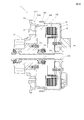
- FIG. 3 is an enlarged view of FIG. 2 and a cross-sectional view showing a unit.
- Action explanatory drawing Sectional drawing which shows the modification of a unit.
- a vehicle 10 provided with a drive motor of this embodiment is a motorcycle and has a frame 11 that forms a vehicle body.
- a pair of front forks 20 as a pair of arms is attached to the head pipe 12 constituting the front end of the frame 11 so as to be steerable.
- a bar handle 14 is attached to the top of the front fork 20.
- a front wheel 30 as a wheel is attached to the lower end of the front fork 20.
- An engine 15 is fixed inside the frame 11.
- An intake device 15 i and an exhaust device 15 o are connected to the engine 15.
- a pair of left and right swing arms 16 are attached to the rear portion of the frame 11 by a pivot shaft 17 so as to freely swing up and down.
- a rear wheel 17 is attached to the rear end of the swing arm 16.
- the rear wheel 17 can be driven by the engine 15 via a drive transmission means such as a chain or a drive shaft (not shown).
- Reference numeral 18 denotes a rear cushion unit having an upper end coupled to the upper rear portion of the frame 11 and a lower end coupled to a lower portion of the swing arm 16 and a lower rear portion of the vehicle body frame 11 via a link mechanism 18b.
- the front wheel 30 is also configured as a drive wheel.
- a braking device is provided for the front wheel 30.
- the front wheel 30 is driven by a motor built in the front wheel 30. 2 and 3, reference numeral 40 denotes a motor.
- the motor 40 has a stator 41 and a rotor 42 and constitutes a drive source for the front wheels 30.
- the front wheel 30 is rotatably supported on the axle 21 between a pair of left and right arms, in this embodiment, the left and right front forks 20L and 20R.
- the motor 40 is disposed in the hub of the front wheel 30.
- a braking mechanism 50 is provided on the front wheel 30. As shown in FIG. 2, when viewed from the front of the vehicle body, the braking mechanism 50 is disposed on one side of the vehicle body center C (on the left side in FIG. 2). On the other hand, the motor 40 is arranged on the other side (right side in FIG. 2) from the vehicle body center C. In this embodiment, when viewed from the front of the vehicle body, the braking mechanism 50, in particular, a braking part 52 that generates a braking force and a braked part 51 that receives the braking force, which will be described later, are disposed between the front forks 20L and 20R. The motor 40 is disposed on the other side of the vehicle body center C between the front forks 20L and 20R.
- the front wheel 30 includes a fixed side member 60 that supports the stator 41 of the motor 40 and a wheel hub 31 as a rotation side member to which the rotation of the rotor 42 is transmitted.
- the front wheel 30 is driven via the wheel hub 31 by the drive of the motor 40.
- the front wheel 30 is fixed to the wheel hub 31 with stud bolts 33.
- the rotor 42 and the rotation side member 31 are rotatably supported by the axle 22.
- the axle 22 is constituted by a cylindrical axle collar 22 through which the axle 21 is inserted. Therefore, the axle 22 is also referred to as an axle collar 22 hereinafter.
- an engaging portion 22p with the fixed side member 60 for positioning the rotation center of the rotation side member 31 relative to the fixed side member 60 is provided.
- the engaging part 22p can be constituted by a small diameter part formed via a step part 22d (FIG. 3).
- the engaging portion on the fixed side member 60 side can be configured by a hole 60h into which the small diameter portion 22p is inserted.
- the rotation side member 31 and the fixed side member 60 engage the engaging portion 22p of the axle collar 22 with the fixed side member 60 (in this embodiment, the small diameter portion 22p is connected to the fixed side member 60).
- the unit U is supported by an axle 21 inserted in an axle collar 22 between a pair of arms 20L and 20R.
- the rotation-side member 31 has a cylindrical portion 31b that is rotatably supported by the axle collar 22 and a flange portion 31f provided on the outer periphery of the cylindrical portion 31b.
- the rotor 42 is fastened to the flange portion 31f by socket bolts 42b.
- socket bolts 42b thus, the rotor 42 is supported by the rotation side member 31.
- the cylindrical portion 31b of the rotation-side member 31 protrudes toward the fixed-side member 60 from the fastening portion of the rotor 42 in the axial direction (left-right direction in FIGS. 2 and 3). Via the axle 22.
- the other end side of the cylindrical portion 31b is rotatably supported on the axle 21 by a bearing 26.
- the rotor 42 is an outer rotor located on the outer periphery of the stator 41.
- the rotor 42 is a member having a substantially U-shaped cross section as a whole, and a magnet 46 is provided on the inner peripheral surface facing the stator 41.
- a central portion of the rotor 42 is fixed to the flange portion 31f of the rotation side member 31 by the socket bolt 42b.
- the stator 41 is configured in a donut shape having a space 41 s (FIG. 3) at the center thereof, and the protruding portion 31 c of the cylindrical portion 31 b of the rotation side member 31 is disposed in the space 41 s.
- FIG. 4 is a diagram illustrating a state in which the engaging portion 22p of the axle collar 22 has started to engage with the engaging portion 60h of the stationary member 60 in the process of configuring the unit U.
- the engaging portion 22 p of the axle collar 22 protrudes toward the fixed side member 60 from the protruding portion 31 c of the cylindrical portion 31 b of the rotating side member 31 in the axial direction.
- FIG. 4 shows that the engaging portion 22p of the axle collar 22 has started to engage with the engaging portion 60h of the stationary member 60 in the process of configuring the unit U.
- the engaging portion 22 p is arranged so that when the rotating side member 31 supporting the rotor 42 and the fixed side member 60 supporting the stator 41 are brought close to each other in the axial direction to form a unit, Before the stator 41 overlaps (more precisely, the attracting force due to the magnetic force acting between the rotor 42 and the stator 41 causes the engaging portion 22p of the axle collar 22 and the engaging portion 60h of the fixed-side member 60). Before engaging with the engaging portion 60h of the fixed side member 60.
- the fixed-side member 60 is rotated from the disk portion 61 fixed to one arm 20 ⁇ / b> L of the pair of arms 20 ⁇ / b> L and 20 ⁇ / b> R and the circumferential portion of the disk portion 61. It has a cylindrical portion 60 b that extends to the side member 31 side and covers the stator 41 and the rotor 42. As shown in FIG. 2, the annular end portion 60e of the cylindrical portion 60b and the outer peripheral portion 31e of the flange portion 31f of the rotation side member 31 overlap on the center line C of the vehicle, and the labyrinth at the overlap portion. A seal 35 is configured.
- the labyrinth seal 35 includes an annular end portion 60e whose diameter is increased toward the rotating side member 31 via a step portion 60d in the cylindrical portion 60b of the fixed side member 60, and
- the rotary side member 31 includes an annular ring-shaped unevenness 31d1 and a radial unevenness 31d2 provided on the outer peripheral portion 31e of the flange portion 31f.
- the axle 21 is composed of an axle bolt, and is fixed to the front ends of the front forks 20L, 20R with an axle nut 21n.
- the fixed member 60, axle collar 22, side collar 23, ball bearing 25, ball bearing 26, and side collar 29 are mounted on the axle 21 from the right side in FIG. 2, and the front fork 20L is mounted on the axle nut 21n. , 20R are fastened together and fixed.
- Oil seals 24 and 28 are mounted between the cylindrical portion 31b and the side collars 23 and 29 in the rotation side member 31, respectively. This prevents water and dust from entering the cylinder portion 31b.
- Circlips 25c and 27 for restricting relative movement in the axial direction with respect to the ball bearings 25 and 26 are mounted on the cylindrical portion 31b.
- a convex portion 61 p is integrally provided on the outer surface of the fixed side member 60, and the convex portion 61 engages with the front fork 20 ⁇ / b> L so that the axle 21 of the fixed side member 60 is engaged. And the rotation around the axle collar 22 is reliably prevented.
- a stator 41 of the motor 40 is fixed by a socket bolt 62 in the fixed side member 60.
- reference numeral 43 denotes a power line of the motor 40.
- the fixed side member 60 is provided with a hole 63 for pulling out the power line 43 to the outside of the fixed side member 60.
- the power line 43 drawn out from the hole 63 is supported by the cover 64 via the grommet 66 and further connected to a motor battery (not shown) as a power source.
- the battery is mounted on the vehicle body frame 11.
- the cover 64 is fixed to the outer surface of the stationary member 60 with bolts 65 (FIG. 1) for the purpose of closing the hole 63.
- a gasket 67 is provided between the cover 64 and the outer surface of the fixed side member 60, and the inside of the cover 64 is airtightly held by the gasket 67 and the grommet 66. Accordingly, water or the like does not enter the fixed side member 60 from the hole 63.
- a magnetic sensor 44 is provided inside the stationary member 60 inside the stator 41 so that the rotation of the rotor 42 can be detected by detecting the magnet 45 provided on the rotor 42. It has become.
- the signal line (not shown) is also drawn in the same manner as the power line 43 and connected to a control device of the motorcycle 10. In FIG. 2, the power line 43 is drawn downward, but this is because the cut surface in FIG. 1 is shown in an expanded state, and actually, it is drawn upward as shown in FIG. It is.
- Wiring (power line 43 and signal line) for the motor 40 can be inserted into the fixed side member 60 at a portion of the fixed side member 60 other than the overlapping portion with the rotation side member 31 (wheel hub) 31.
- the wiring is inserted through the hole 63 of the fixed side member 60 behind the front fork 20L and arranged along the front fork 20L.
- the power line 43 and the signal line are connected to a control device (not shown) attached to a proper position of the vehicle body frame 11.
- the braking mechanism 50 is fixed to the wheel hub 31 and rotates together with the wheel hub 31 (and therefore the front wheel 30), and the braking that brakes the rotation of the braked portion 51.
- the braked part 51 is constituted by a brake disk fixed to the outer surface of the wheel hub 31 by a bolt 53
- the braking part 52 is constituted by a caliper fixed to the front fork 20R.
- the braking part 52 and the braked part 51 are located between the front forks 20L and 20R.
- the caliper 52 can adopt a known structure, and includes a pair of brake pads 54 that press and brake the brake disc 51 from both sides.
- the axle 22 that rotatably supports the rotor 42 and the rotation-side member 31 is provided with an engaging portion 22p for positioning the rotation center of the rotation-side member 31 relative to the fixed-side member 60 with the fixed-side member 60. Therefore, as shown in FIG. 3, when the engaging portion 22 p is engaged with the fixed side member 60 and the rotating side member 31 and the fixed side member 60 are unitized, the axle 22 is in contact with the fixed side member 60. The center of the insertion hole of the axle 21 in both is aligned. Therefore, the operation of assembling the unit U (and hence the wheel 30) between the pair of arms 20L and 20R is facilitated.
- the rotation-side member 31 has a cylindrical portion 31b that is rotatably supported by the axle 22, and a flange portion 31f provided on the outer periphery of the cylindrical portion 31b, and a rotor 42 is fastened to the flange portion 31f.
- the rotor 42 is an outer rotor positioned on the outer periphery of the stator 41.
- the stator 41 is a donut shape having a space 41s at the center thereof, and the protruding portion 31c of the cylindrical portion 31b of the rotation side member 31 is formed in the space 41s. Therefore, the wheel 30 can be downsized by effectively using the space 41 s at the center of the stator 41.
- the engaging portion 22p of the axle 22 is protruded toward the fixed side member 60 from the protruding portion 31c of the cylindrical portion 31b of the rotating side member 31 with respect to the axial direction, and the rotating side member 31 that supports the rotor 42;
- the engaging portion 22p is engaged with the fixed side member 60 before the rotor 42 and the stator 41 overlap as shown in FIG. Therefore, the engaging portion 22p can be engaged with the fixed-side member 60 before the attracting force generated between the rotor 42 and the stator 41 becomes strong. Therefore, the unitization can be easily performed.
- the fixed side member 60 extends to the rotating side member 31 side from the disc portion 61 fixed to one arm 20R of the pair of arms 20L and 20R and the circumferential portion of the disc portion 61.
- the cylindrical portion 60b that covers the stator 41 and the rotor 42, and the annular end portion 60e of the cylindrical portion 60b and the rotation side member 31 are overlapped on the center line C of the vehicle.
- the labyrinth seal 35 can be configured at a position where it is difficult to enter.
- An annular end 60e of the cylindrical portion 60b is provided with a step portion 60d whose diameter increases toward the rotation-side member 31.
- the rotation-side member 31 has an unevenness 31d1 in the axial direction and an unevenness 301d2 in the radial direction. Since the labyrinth seal 35 is provided, the sealing performance can be improved.
- FIG. 5 is a cross-sectional view showing a modification of the unit U.
- the feature of the unit U is that an end portion 22b of an axle (axle collar) 22 is extended as a small-diameter cylindrical portion, and this extension portion 22b is engaged with a ball bearing 26 and a side collar 29, whereby the axle collar 22 The ball bearing 26 and the side collar 29 are positioned. If comprised in this way, while the positioning of the rotation center of the rotation side member 31 with respect to the axle collar 22 can be performed reliably, insertion to the axle collar 22 of the axle 21 can be performed more smoothly. Therefore, the operation of assembling the unit U (and hence the wheel 30) between the pair of arms 20L and 20R is further facilitated.
- the vehicle including the drive motor according to the present invention facilitates the work of assembling the wheel including the unit including the drive motor between the pair of arms, and thus is useful for manufacturing the vehicle including the drive motor in the wheel. is there.
- Body center U unit 10 Vehicle 11 Body 20 Arm (front fork) 21 axle 22 axle (axle collar) 22p engagement part 30 wheel (front wheel) 31 Rotating member (wheel hub) 31b Tube part 31f Flange part 31e Annular end part 35 Labyrinth seal 40 Motor 41 Rotor 42 Stator 50 Braking mechanism 60 Fixed side member 60b Cylindrical part 61 Disk part
Landscapes
- Engineering & Computer Science (AREA)
- Power Engineering (AREA)
- Mechanical Engineering (AREA)
- Manufacturing & Machinery (AREA)
- Chemical & Material Sciences (AREA)
- Combustion & Propulsion (AREA)
- Transportation (AREA)
- Arrangement Or Mounting Of Propulsion Units For Vehicles (AREA)
- Connection Of Motors, Electrical Generators, Mechanical Devices, And The Like (AREA)
- Permanent Magnet Type Synchronous Machine (AREA)
Abstract
Priority Applications (10)
| Application Number | Priority Date | Filing Date | Title |
|---|---|---|---|
| EP10848429.6A EP2551995B1 (fr) | 2010-03-26 | 2010-03-26 | Véhicule équipé d'un moteur d'entraînement |
| CA2792531A CA2792531C (fr) | 2010-03-26 | 2010-03-26 | Vehicule equipe d'un moteur d'entrainement |
| CN201080065401.5A CN102804555B (zh) | 2010-03-26 | 2010-03-26 | 具有驱动马达的车辆 |
| JP2012506746A JP5508519B2 (ja) | 2010-03-26 | 2010-03-26 | 駆動用モータを備える車両 |
| PCT/JP2010/055439 WO2011118036A1 (fr) | 2010-03-26 | 2010-03-26 | Véhicule équipé d'un moteur d'entraînement |
| ES10848429.6T ES2619584T3 (es) | 2010-03-26 | 2010-03-26 | Vehículo provisto de un motor de accionamiento |
| BR112012024208-3A BR112012024208A2 (pt) | 2010-03-26 | 2010-03-26 | veículo equipado com motor de acionamento |
| KR1020127023120A KR101435306B1 (ko) | 2010-03-26 | 2010-03-26 | 구동용 모터를 구비하는 차량 |
| US13/636,213 US8813886B2 (en) | 2010-03-26 | 2010-03-26 | Vehicle equipped with driving motor |
| TW100108294A TWI447043B (zh) | 2010-03-26 | 2011-03-11 | A vehicle with a motor for driving |
Applications Claiming Priority (1)
| Application Number | Priority Date | Filing Date | Title |
|---|---|---|---|
| PCT/JP2010/055439 WO2011118036A1 (fr) | 2010-03-26 | 2010-03-26 | Véhicule équipé d'un moteur d'entraînement |
Publications (1)
| Publication Number | Publication Date |
|---|---|
| WO2011118036A1 true WO2011118036A1 (fr) | 2011-09-29 |
Family
ID=44672625
Family Applications (1)
| Application Number | Title | Priority Date | Filing Date |
|---|---|---|---|
| PCT/JP2010/055439 WO2011118036A1 (fr) | 2010-03-26 | 2010-03-26 | Véhicule équipé d'un moteur d'entraînement |
Country Status (10)
| Country | Link |
|---|---|
| US (1) | US8813886B2 (fr) |
| EP (1) | EP2551995B1 (fr) |
| JP (1) | JP5508519B2 (fr) |
| KR (1) | KR101435306B1 (fr) |
| CN (1) | CN102804555B (fr) |
| BR (1) | BR112012024208A2 (fr) |
| CA (1) | CA2792531C (fr) |
| ES (1) | ES2619584T3 (fr) |
| TW (1) | TWI447043B (fr) |
| WO (1) | WO2011118036A1 (fr) |
Cited By (5)
| Publication number | Priority date | Publication date | Assignee | Title |
|---|---|---|---|---|
| JP2018511517A (ja) * | 2015-03-23 | 2018-04-26 | フレニ・ブレンボ エス・ピー・エー | 自動車両および制動に用いる電気モータアセンブリ |
| WO2023079844A1 (fr) * | 2021-11-05 | 2023-05-11 | パナソニックIpマネジメント株式会社 | Moteur, soufflante et véhicule |
| WO2023089937A1 (fr) * | 2021-11-18 | 2023-05-25 | いすゞ自動車株式会社 | Moteur-roue |
| WO2023089935A1 (fr) * | 2021-11-18 | 2023-05-25 | いすゞ自動車株式会社 | Moteur-roue |
| WO2023089934A1 (fr) * | 2021-11-18 | 2023-05-25 | いすゞ自動車株式会社 | Moteur-roue |
Families Citing this family (6)
| Publication number | Priority date | Publication date | Assignee | Title |
|---|---|---|---|---|
| JP5149938B2 (ja) * | 2010-06-11 | 2013-02-20 | 株式会社シマノ | モータ内蔵自転車用ハブ |
| US10308352B2 (en) * | 2014-12-12 | 2019-06-04 | Borealis Technical Limited | Monitoring system for aircraft drive wheel system |
| CN107709147B (zh) * | 2015-06-19 | 2020-03-06 | 罗伯特·博世有限公司 | 电动车辆以及用于电动车辆的驱动系统 |
| JP6584198B2 (ja) * | 2015-07-31 | 2019-10-02 | Ntn株式会社 | 発電機付き車輪用軸受装置 |
| US11143309B2 (en) * | 2018-10-09 | 2021-10-12 | Hamilton Sundstrand Corporation | Disconnect bearing and input seal for a variable frequency starter generator |
| PE20211436A1 (es) * | 2018-12-13 | 2021-08-05 | Bajaj Auto Ltd | Un vehiculo electrico |
Citations (2)
| Publication number | Priority date | Publication date | Assignee | Title |
|---|---|---|---|---|
| JP2008057552A (ja) * | 2006-08-29 | 2008-03-13 | Honda Motor Co Ltd | ホイール回転装置のブレーキ構造 |
| JP2009159791A (ja) | 2007-12-27 | 2009-07-16 | Yamaha Motor Co Ltd | 二輪車、及び二輪車の駆動装置 |
Family Cites Families (22)
| Publication number | Priority date | Publication date | Assignee | Title |
|---|---|---|---|---|
| DE4218888C2 (de) * | 1992-06-09 | 1995-06-08 | Barth Hubert Dipl Ing Fh | Elektrische Maschine |
| JP3363682B2 (ja) * | 1995-12-19 | 2003-01-08 | 株式会社ミツバ | 磁石発電機 |
| AT405390B (de) * | 1997-03-19 | 1999-07-26 | Abb Daimler Benz Transp | Elektromotorischer radnabenantrieb für ein fahrzeugrad |
| US6199651B1 (en) * | 1997-12-11 | 2001-03-13 | Vectrix Corporation | Vehicle drive wheel assembly |
| GB2369503A (en) * | 2000-11-28 | 2002-05-29 | Evt Technology Co Ltd | Direct-drive wheel motor |
| TWI268320B (en) * | 2001-12-04 | 2006-12-11 | Yamaha Motor Co Ltd | Continuously variable transmission and method of controlling it allowing for control of the axial position of a movable sheave without a sensor for measuring the axial position of the movable sheave on a rotational shaft and for stable control with the movable sheave being held in position |
| DE60203943T2 (de) * | 2002-01-04 | 2006-02-16 | Sascha Mantovani | Elektrischer motor mit an das zu drehende element gekoppeltem rotor |
| IL149815A0 (en) * | 2002-05-23 | 2002-11-10 | Tzora Active Systems Ltd | Hub motor |
| JP2004312845A (ja) * | 2003-04-04 | 2004-11-04 | Nissan Motor Co Ltd | モータ用ステータ |
| JP2004357451A (ja) * | 2003-05-30 | 2004-12-16 | Hitachi Ltd | 車両用交流発電機 |
| DE10338659A1 (de) * | 2003-08-22 | 2005-03-17 | Magnet-Motor Gesellschaft Für Magnetmotorische Technik Mbh | Elektrische Antriebseinheit für ein Kraftfahrzeug |
| TWI283103B (en) * | 2004-02-06 | 2007-06-21 | Yamaha Motor Co Ltd | Rotating electric machine and electrically driven vehicle |
| JP2005335535A (ja) * | 2004-05-27 | 2005-12-08 | Sanyo Electric Co Ltd | 電動車輪用ハブユニット及び該ハブユニットを具えた乗物 |
| JP4297859B2 (ja) * | 2004-09-28 | 2009-07-15 | 三洋電機株式会社 | 電動車輪用ハブユニット及び該ハブユニットを具えた乗物 |
| JP4450208B2 (ja) * | 2005-01-19 | 2010-04-14 | 三菱自動車工業株式会社 | インホイールモータ |
| JP4969873B2 (ja) * | 2005-08-05 | 2012-07-04 | ヤマハ発動機株式会社 | 回転電機を搭載する鞍乗型車両、及び回転電機の取り付け方法 |
| JP4672490B2 (ja) * | 2005-09-05 | 2011-04-20 | 本田技研工業株式会社 | チェーン駆動の自動二輪車の後輪用ブレーキ装置及びチェーン駆動の自動二輪車の後輪用ブレーキの固定方法 |
| NL1030984C2 (nl) * | 2006-01-23 | 2007-07-24 | Gear Chain Ind Bv | Elektrische rijwielnaaf. |
| JP2008044588A (ja) * | 2006-08-18 | 2008-02-28 | Junichi Yoshimori | 二輪車のハイブリット機能を可能にした発電機兼用駆動モーター |
| JP4724075B2 (ja) * | 2006-08-29 | 2011-07-13 | 本田技研工業株式会社 | ホイール回転装置 |
| TWM349343U (en) * | 2008-09-02 | 2009-01-21 | Kmc Chain Ind Co Ltd | Driving device of electric vehicle |
| JP5185360B2 (ja) * | 2010-12-24 | 2013-04-17 | 株式会社シマノ | モータ内蔵自転車用ハブ |
-
2010
- 2010-03-26 WO PCT/JP2010/055439 patent/WO2011118036A1/fr active Application Filing
- 2010-03-26 CA CA2792531A patent/CA2792531C/fr not_active Expired - Fee Related
- 2010-03-26 US US13/636,213 patent/US8813886B2/en not_active Expired - Fee Related
- 2010-03-26 EP EP10848429.6A patent/EP2551995B1/fr not_active Not-in-force
- 2010-03-26 CN CN201080065401.5A patent/CN102804555B/zh active Active
- 2010-03-26 ES ES10848429.6T patent/ES2619584T3/es active Active
- 2010-03-26 BR BR112012024208-3A patent/BR112012024208A2/pt not_active Application Discontinuation
- 2010-03-26 KR KR1020127023120A patent/KR101435306B1/ko active IP Right Grant
- 2010-03-26 JP JP2012506746A patent/JP5508519B2/ja active Active
-
2011
- 2011-03-11 TW TW100108294A patent/TWI447043B/zh not_active IP Right Cessation
Patent Citations (2)
| Publication number | Priority date | Publication date | Assignee | Title |
|---|---|---|---|---|
| JP2008057552A (ja) * | 2006-08-29 | 2008-03-13 | Honda Motor Co Ltd | ホイール回転装置のブレーキ構造 |
| JP2009159791A (ja) | 2007-12-27 | 2009-07-16 | Yamaha Motor Co Ltd | 二輪車、及び二輪車の駆動装置 |
Non-Patent Citations (1)
| Title |
|---|
| See also references of EP2551995A4 * |
Cited By (11)
| Publication number | Priority date | Publication date | Assignee | Title |
|---|---|---|---|---|
| JP2018511517A (ja) * | 2015-03-23 | 2018-04-26 | フレニ・ブレンボ エス・ピー・エー | 自動車両および制動に用いる電気モータアセンブリ |
| WO2023079844A1 (fr) * | 2021-11-05 | 2023-05-11 | パナソニックIpマネジメント株式会社 | Moteur, soufflante et véhicule |
| WO2023089937A1 (fr) * | 2021-11-18 | 2023-05-25 | いすゞ自動車株式会社 | Moteur-roue |
| WO2023089935A1 (fr) * | 2021-11-18 | 2023-05-25 | いすゞ自動車株式会社 | Moteur-roue |
| WO2023089934A1 (fr) * | 2021-11-18 | 2023-05-25 | いすゞ自動車株式会社 | Moteur-roue |
| JP2023074773A (ja) * | 2021-11-18 | 2023-05-30 | いすゞ自動車株式会社 | インホイールモータ |
| JP2023074774A (ja) * | 2021-11-18 | 2023-05-30 | いすゞ自動車株式会社 | インホイールモータ |
| JP2023074772A (ja) * | 2021-11-18 | 2023-05-30 | いすゞ自動車株式会社 | インホイールモータ |
| JP7338671B2 (ja) | 2021-11-18 | 2023-09-05 | いすゞ自動車株式会社 | インホイールモータ |
| JP7342092B2 (ja) | 2021-11-18 | 2023-09-11 | いすゞ自動車株式会社 | インホイールモータ |
| JP7435581B2 (ja) | 2021-11-18 | 2024-02-21 | いすゞ自動車株式会社 | インホイールモータ |
Also Published As
| Publication number | Publication date |
|---|---|
| TWI447043B (zh) | 2014-08-01 |
| ES2619584T3 (es) | 2017-06-26 |
| US8813886B2 (en) | 2014-08-26 |
| CA2792531C (fr) | 2016-11-01 |
| EP2551995A1 (fr) | 2013-01-30 |
| CN102804555A (zh) | 2012-11-28 |
| CA2792531A1 (fr) | 2011-09-29 |
| CN102804555B (zh) | 2014-12-03 |
| JPWO2011118036A1 (ja) | 2013-07-04 |
| US20130009451A1 (en) | 2013-01-10 |
| BR112012024208A2 (pt) | 2020-08-11 |
| TW201206764A (en) | 2012-02-16 |
| EP2551995B1 (fr) | 2017-03-01 |
| KR101435306B1 (ko) | 2014-08-27 |
| KR20120118849A (ko) | 2012-10-29 |
| JP5508519B2 (ja) | 2014-06-04 |
| EP2551995A4 (fr) | 2015-07-22 |
Similar Documents
| Publication | Publication Date | Title |
|---|---|---|
| JP5508519B2 (ja) | 駆動用モータを備える車両 | |
| JP4348941B2 (ja) | 車輪用回転電機の取付構造 | |
| JP4225134B2 (ja) | 車両用懸架装置 | |
| KR101189975B1 (ko) | 모터 구동 차량 | |
| WO2013179643A1 (fr) | Structure de palier | |
| JP4730078B2 (ja) | インホイールモータ | |
| JP5506223B2 (ja) | モータ駆動車両 | |
| JP6729492B2 (ja) | 駆動装置 | |
| JP6464130B2 (ja) | パルサーリング取付構造 | |
| JP5506222B2 (ja) | モータ駆動車両 | |
| JP5061818B2 (ja) | 車輪支持装置 | |
| JP4258222B2 (ja) | センサ組立体、シール装置ならびに転がり軸受装置 | |
| JP3706845B2 (ja) | アクスルハブの支持構造 | |
| JP2005067261A (ja) | パーキングブレーキ構造 | |
| KR100368652B1 (ko) | 차량용 액슬 어셈블리 | |
| JP2005162159A (ja) | 電動車両用車輪構造 | |
| JP4031131B2 (ja) | ダンパ付きホイール構造 | |
| JP5863275B2 (ja) | 自動二輪車の懸架構造 | |
| JPH0516604A (ja) | 自動二輪車等のホイール支持装置 | |
| JPS62210102A (ja) | 自動二輪車等の車両における車軸の軸受部構造 | |
| JP2017035936A (ja) | 車両の駆動輪構造 | |
| JP2003034282A (ja) | メーターケーブル用ギヤユニットの連結構造 |
Legal Events
| Date | Code | Title | Description |
|---|---|---|---|
| WWE | Wipo information: entry into national phase |
Ref document number: 201080065401.5 Country of ref document: CN |
|
| 121 | Ep: the epo has been informed by wipo that ep was designated in this application |
Ref document number: 10848429 Country of ref document: EP Kind code of ref document: A1 |
|
| ENP | Entry into the national phase |
Ref document number: 20127023120 Country of ref document: KR Kind code of ref document: A |
|
| ENP | Entry into the national phase |
Ref document number: 2792531 Country of ref document: CA |
|
| WWE | Wipo information: entry into national phase |
Ref document number: 13636213 Country of ref document: US |
|
| WWE | Wipo information: entry into national phase |
Ref document number: 2012506746 Country of ref document: JP |
|
| WWE | Wipo information: entry into national phase |
Ref document number: IDW00201203838 Country of ref document: ID |
|
| NENP | Non-entry into the national phase |
Ref country code: DE |
|
| REEP | Request for entry into the european phase |
Ref document number: 2010848429 Country of ref document: EP |
|
| WWE | Wipo information: entry into national phase |
Ref document number: 1201004938 Country of ref document: TH Ref document number: 2010848429 Country of ref document: EP |
|
| WWE | Wipo information: entry into national phase |
Ref document number: 9051/CHENP/2012 Country of ref document: IN |
|
| REG | Reference to national code |
Ref country code: BR Ref legal event code: B01A Ref document number: 112012024208 Country of ref document: BR |
|
| ENP | Entry into the national phase |
Ref document number: 112012024208 Country of ref document: BR Kind code of ref document: A2 Effective date: 20120924 |