WO2011114796A1 - 記録テープカートリッジ - Google Patents
記録テープカートリッジ Download PDFInfo
- Publication number
- WO2011114796A1 WO2011114796A1 PCT/JP2011/052432 JP2011052432W WO2011114796A1 WO 2011114796 A1 WO2011114796 A1 WO 2011114796A1 JP 2011052432 W JP2011052432 W JP 2011052432W WO 2011114796 A1 WO2011114796 A1 WO 2011114796A1
- Authority
- WO
- WIPO (PCT)
- Prior art keywords
- case
- recording tape
- tape cartridge
- security tag
- reel
- Prior art date
- Legal status (The legal status is an assumption and is not a legal conclusion. Google has not performed a legal analysis and makes no representation as to the accuracy of the status listed.)
- Ceased
Links
Images







Classifications
-
- G—PHYSICS
- G11—INFORMATION STORAGE
- G11B—INFORMATION STORAGE BASED ON RELATIVE MOVEMENT BETWEEN RECORD CARRIER AND TRANSDUCER
- G11B23/00—Record carriers not specific to the method of recording or reproducing; Accessories, e.g. containers, specially adapted for co-operation with the recording or reproducing apparatus ; Intermediate mediums; Apparatus or processes specially adapted for their manufacture
- G11B23/02—Containers; Storing means both adapted to cooperate with the recording or reproducing means
- G11B23/04—Magazines; Cassettes for webs or filaments
- G11B23/041—Details
- G11B23/042—Auxiliary features
Definitions
- the present invention relates to a recording tape cartridge having a reel on which a recording tape such as a magnetic tape is wound, and more particularly to a recording tape cartridge having a security function.
- a recording tape cartridge in which a recording tape such as a magnetic tape is wound around a reel and the reel is accommodated in a case is known. Since this recording tape cartridge is often used as a data recording / reproducing medium (data backup) for a computer or the like, security measures for theft prevention may be taken.
- the security tag described in Patent Document 1 has a columnar shape including a coil formed by winding a wire around the outer peripheral surface of a magnetic core, and its axis is perpendicular to the bottom plate of the case.
- the present invention provides a recording tape cartridge capable of preventing the communication performance of the security tag from deteriorating at least when the case of the recording tape cartridge is stacked on the case of another recording tape cartridge. Objective.
- a recording tape cartridge includes a case that houses a reel around which a recording tape is wound, and a security that is provided in the case and that can be transmitted to and received from the outside.
- the security tag in the case of another recording tape cartridge is installed in the case so that the axis does not overlap.
- the security tag is installed so that the axis is not perpendicular to the bottom plate of the case.
- the security tag is installed so that the axis is substantially parallel to the bottom plate of the case.
- the recording tape cartridge according to a fourth aspect of the present invention is the recording tape cartridge according to the aspect described above, wherein the security tag is perpendicular to the peripheral wall of the case when viewed from the axial direction of the reel. It is installed so that it does not become.
- a recording tape cartridge according to a fifth aspect of the present invention is the recording tape cartridge according to the aspect described above, wherein the security tag is provided in the case, and the security tag is arranged in an axial direction of the reel and a direction orthogonal to the axial direction.
- a holding member formed on one end side for holding in cooperation with the case, and a cover member formed in the case and fitted with a fitting portion formed on the other end side of the holding member. And a fitting portion.
- the holding portion formed on the holding member holds the security tag from the reel axial direction and the direction orthogonal to the axial direction in cooperation with the case. That is, the holding member contacts the security tag only from the axial direction of the reel and the direction orthogonal to the axial direction. Therefore, the holding member can be held even when the shape of the security tag is changed, and the degree of freedom in designing the security tag can be improved.
- the recording tape cartridge according to a sixth aspect of the present invention is the recording tape cartridge according to the above aspect, wherein the holding member can be mounted in the case in a state where the security tag is provided in the case. Is formed.
- the holding member can be attached even if the shape of the security tag is changed. Therefore, the degree of freedom in designing the security tag can be improved.
- a recording tape cartridge includes a substantially rectangular case that accommodates a reel on which a recording tape is wound, a security tag that is provided in the case and can be transmitted and received with the outside,
- the security tag has a columnar shape with a coil formed by winding a wire around the outer peripheral surface of a magnetic core, and the case is adjacent to the case of another recording tape cartridge.
- the magnetic tag is magnetically coupled to the security tag installed in each case. It does not occur. Therefore, the communication performance of the security tag does not deteriorate.
- a recording tape cartridge capable of preventing the communication performance of the security tag from being deteriorated at least when the case of the recording tape cartridge is stacked on the case of another recording tape cartridge. Can do.
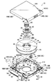
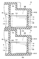
- Schematic perspective view of recording tape cartridge Schematic exploded perspective view of the recording tape cartridge as viewed from above Schematic exploded perspective view of the recording tape cartridge as viewed from below Schematic plan view of the lower case with the security tag placed horizontally Schematic cross-sectional view showing a state in which cases with security tags placed horizontally are stacked
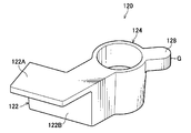
- Schematic perspective view of holding member Schematic plan view of holding member
- Schematic bottom view of holding member Schematic sectional view of the fitting part in the holding member
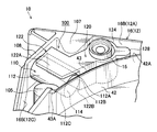
- Schematic perspective view of the lower case showing the holding member holding the horizontally placed security tag
- Schematic plan view of the lower case showing the holding member holding the horizontally placed security tag
- Schematic cross-sectional view of the lower case showing the holding member that holds the security tag placed horizontally
- Schematic perspective view of the lower case with the security tag placed diagonally with respect to the vertical direction Schematic plan view of the lower case with the security tag placed diagonally with respect to the vertical direction
- FIG. 1 the loading direction of the recording tape cartridge 10 into the drive device is indicated by an arrow A, which is the forward direction (front side) of the recording tape cartridge 10.
- the arrow B direction orthogonal to the arrow A is the right direction (right side).
- a direction orthogonal to the arrow A direction and the arrow B direction is indicated by an arrow C, which is an upward direction (upper side) of the recording tape cartridge 10.
- the recording tape cartridge 10 has a case 12 having a substantially rectangular box shape.
- an upper case 14 and a lower case 16 made of resin such as polycarbonate (PC) are respectively provided with a peripheral wall 14B standing on the periphery of the top plate 14A, and a peripheral wall 16B standing on the periphery of the bottom plate 16A.
- PC polycarbonate
- screw bosses 15 are formed in the vicinity of each corner portion in the upper case 14 and the lower case 16, and a screw (not shown) is screwed into the screw boss 15 from the lower surface side of the lower case 16. 12 can be assembled. In the case 12, only one reel 20 is rotatably accommodated.
- a bottomed cylindrical reel hub 22 constituting an axial center portion and a lower flange 26 provided at a lower end portion thereof are integrally formed, and an upper flange 24 is ultrasonically welded to an upper end portion of the reel hub 22.
- a recording tape T such as a magnetic tape as an information recording / reproducing medium is wound on the outer peripheral surface of the reel hub 22, and the end of the wound recording tape T in the width direction is wound by the upper flange 24 and the lower flange 26. Part is held.
- a reel gear 44 is formed in an annular shape on the lower surface (outer surface) of the bottom wall (bottom portion) 28 of the reel hub 22, and a gear opening for exposing the reel gear 44 to the outside is formed in the central portion of the lower case 16. 40 is drilled. The reel gear 44 exposed from the gear opening 40 is engaged with a drive gear (not shown) formed on a rotation shaft (not shown) of the drive device and is driven to rotate. Relative rotation with respect to the case 12 is possible.
- a reel plate 46 which is an annular metal plate made of a magnetic material, is fixed coaxially and integrally to the inside of the reel gear 44 on the lower surface of the bottom wall 28 by insert molding. It is attracted and held by the magnetic force of an annular magnet (not shown) provided on the rotating shaft.
- the reel 20 is partially projected on the inner surface of the top plate 14A of the upper case 14 and the inner surface of the bottom plate 16A of the lower case 16, and accommodates the reel 20 on a circular locus coaxial with the gear opening 40. It is held so as not to rattle by an idle regulation wall 42 as an inner wall that defines the area.
- An opening 18 for pulling out the recording tape T wound around the reel 20 is formed in the right wall 12B of the case 12, and a drive tape is drawn from the opening 18 at the free end of the recording tape T.
- a leader pin 30 as a leader member that is pulled out while being locked (engaged) by a drawing member (not shown) of the apparatus is fixed.
- An annular groove 32 is formed at both end portions of the leader pin 30 protruding from the width direction end portion of the recording tape T, and the annular groove 32 is locked to a hook or the like of the drawing member. Yes.
- a pair of upper and lower pin holding portions 36 for positioning and holding the leader pin 30 in the case 12 on the inner side of the opening 18 of the case 12, that is, on the inner surface of the top plate 14 A of the upper case 14 and the inner surface of the bottom plate 16 A of the lower case 16.
- the pin holding portion 36 has a substantially semicircular shape with the drawing tape T drawn side open, and both end portions 34 of the leader pin 30 in an upright state can enter and leave the pin holding portion 36 from the open side. Has been.
- a leaf spring 38 is fixedly disposed in the vicinity of the pin holding portion 36, and the bifurcated tip portion of the leaf spring 38 is engaged with the upper and lower end portions 34 of the leader pin 30.
- the leader pin 30 is held by the pin holding portion 36.
- the tip of the leaf spring 38 is appropriately elastically deformed to allow movement of the leader pin 30.
- the opening 18 is opened and closed by a door 50.
- the door 50 is formed in a substantially rectangular plate shape having a size capable of closing the opening 18, and is provided on the top plate 14 ⁇ / b> A and the bottom plate 16 ⁇ / b> A inside the opening 18 so as to move along the right wall 12 ⁇ / b> B of the case 12.
- a groove portion 64 is formed in which the upper and lower end portions of 50 are slidably fitted.
- a shaft 52 projects from the center of the rear end of the door 50, and a coil spring 58 is inserted into the shaft 52.
- An enlarged portion 54 that prevents the coil spring 58 from falling off is formed at the rear end of the shaft 52.
- the lower case 16 is provided with a support base 60 having a locking portion 62 that locks the rear end of the coil spring 58 inserted into the shaft 52.
- the door 50 is slidably supported on the support base 60 and the rear end of the coil spring 58 is locked to the locking portion 62, so that the door 50 is always urged by the urging force of the coil spring 58.
- the opening 18 is biased in the closing direction.
- a support base 66 that supports the shaft 52 is further protruded on the rear side of the support base 60.
- a convex portion 56 for opening / closing operation is provided protruding outward.
- the convex portion 56 engages with an opening / closing member (not shown) on the drive device side as the recording tape cartridge 10 is loaded into the drive device.
- the door 50 is configured to be opened against the urging force of the coil spring 58.
- a write protect 70 which is set to enable / disable recording on the recording tape T, is provided at the left rear portion of the case 12 so as to be slidable in the left-right direction.
- An opening 68 is formed in the rear wall 12D for projecting an operation projection 72 for operating the write protect 70 manually.
- the opening 68 is formed by a notch 68A formed in the peripheral wall 14B of the upper case 14 and a notch 68B formed in the peripheral wall 16B of the lower case 16 when the upper case 14 and the lower case 16 are joined. It is the structure formed.
- the bottom plate 16A of the lower case 16 is provided with a long hole 69 through which the protrusion 74 of the write protect 70 is exposed in the left-right direction so that the recording tape cartridge 10 is loaded into the drive device.
- the position of the write protect 70 is detected on the drive device side, and whether or not recording on the recording tape T is possible is automatically determined.
- the protrusion 74 does not protrude from the lower surface of the bottom plate 16A of the lower case 16.
- a memory board M storing various information such as recording capacity and recording format is arranged at a predetermined inclination angle (for example, 45 °). Yes.
- a plurality of engagement gears 48 (for example, three at intervals of 120 °) are provided on the periphery of the upper surface of the bottom wall 28 of the reel hub 22 with a predetermined gap therebetween (for example, at 120 ° intervals).
- a plurality of through-holes 28A (in this case, three at intervals of 120 °) are formed at predetermined positions on the reel gear 44 between the engaging gears 48.
- a disc-shaped braking member 80 formed of a resin material is inserted into the reel hub 22.
- a braking gear 84 that can mesh with the engaging gear 48 is formed in an annular shape on the periphery of the lower surface 80 ⁇ / b> A of the braking member 80.
- the upper surface of the braking member 80 faces downward from the inner surface of the top plate 14 ⁇ / b> A of the upper case 14.
- An engagement protrusion 86 having a substantially cross-shaped rotation restriction rib 76 that is protruded and inserted therein is erected so as to be slightly higher than the height of the rotation restriction rib 76. Yes.
- the braking member 80 is not rotatable with respect to the case 12 (upper case 14), and is movable in the vertical direction within the reel hub 22.
- a compression coil spring 98 is disposed between the upper case 14 and the braking member 80. That is, one end of the compression coil spring 98 abuts on the inner side (between the rotation restricting rib 76 and the annular protrusion 78) of the annular protrusion 78 provided on the outer side of the rotation restricting rib 76 of the upper case 14, and the other end is the braking member. 80 is arranged in contact with an annular groove 88 provided on the upper surface of 80. Due to the biasing force of the compression coil spring 98, the braking member 80 is constantly biased downward.
- the braking gear 84 is always meshed with the engagement gear 48 and the relative rotation of the reel 20 with respect to the case 12 is prevented. The rotation is locked. At this time, the reel 20 is pressed against the lower case 16 side by this urging force, and the reel gear 44 is exposed from the gear opening 40.
- a release member 90 having a substantially equilateral triangular shape in a plan view formed of a resin material is inserted inside the reel hub 22 and below the braking member 80 (between the bottom wall 28 and the braking member 80).
- the release member 90 is provided with a plurality of through holes 92 (three in the drawing) having a predetermined shape at appropriate positions, so that the release member 90 is reduced in weight.
- leg portions 94 protruding from the lower surface of the bottom wall 28 to the reel gear 44 by a predetermined height are provided on the lower surface of each of the release members 90 and at the respective vertex portions.
- a flat support convex portion 96 is formed at the center of the upper surface 90A of the release member 90, and a substantially hemispherical release protrusion 82 protruding from the center of the lower surface 80A of the braking member 80 comes into contact therewith. (See FIGS. 2 and 3). As a result, the contact area between the braking member 80 and the release member 90 is reduced, and the sliding resistance during use (during rotation of the reel 20) is reduced.
- a positioning member (not shown) provided in the drive device is inserted into the front wall 12A side on the bottom surface of the bottom plate 16A of the lower case 16 for positioning. Are formed so as to be spaced apart in the left-right direction (see FIG. 3).
- the right hole 102 is formed in a substantially circular shape
- the left hole 104 is formed in a substantially elliptical shape that is long in the left-right direction.
- the positioning member is reliably inserted, and the positional shift is corrected.
- bag portions 103 and 105 as bosses constituting the hole portions 102 and 104 are formed in a convex shape (projection shape) protruding toward the upper case 14 ( (See FIG. 2).
- the front wall 12A (the peripheral wall 16B) on the front side of the hole portion 104 (bag portion 105) of the lower case 16 is formed with a concave portion 106 having a substantially “V” shape when viewed from the bottom (FIGS. 1 to 3). reference).
- the recess 106 is engaged with a position regulating member (not shown) provided in the drive device. The position in the loading direction is regulated.
- a projecting wall 107 having a substantially triangular shape in plan view is formed on the inner surface of the front wall 12A (peripheral wall 16B) so as to project rearward by forming the recess 106 (see FIG. 2). ). Further, a standing wall 108 having the same height is integrally connected to the left side wall of the overhanging wall portion 107 in the diagonally leftward direction, and the standing wall 108 is a left wall 12C (peripheral wall 16B) of the lower case 16. ) Are integrally connected at the same height (see FIG. 10).
- the vertical wall 108, the peripheral wall 16 ⁇ / b> B continuously provided from the vertical wall 108, the overhanging wall portion 107, the screw boss 15 at the left front corner portion of the case 12, the floating regulation wall 42, and the bag portion 105 are almost enclosed.
- the installed space 100 is set as an installation space 100, and a security tag 110 described later is arranged in the installation space 100.
- the security function added to the recording tape cartridge 10 will be described next. That is, the security tag 110 provided in the case 12 of the recording tape cartridge 10 in order to prevent the recording tape cartridge 10 from being carried out from a predetermined security area will be described.
- the security tag 110 is arranged at a predetermined position in the installation space 100 formed at the left front corner (corner) of the case 12. Does not fluctuate significantly. That is, the security tag 110 is arranged at substantially the same position in each recording tape cartridge 10.
- the security tag 110 includes a columnar magnetic core having flanges formed at both ends, and a coil formed by winding a wire around the outer peripheral surface sandwiched between the flanges of the magnetic core, and has a circular shape as a whole. It is configured in a columnar shape (see FIGS. 2 to 5 and FIGS. 10 to 15).
- lead terminals of capacitors (not shown) are connected in parallel to both ends of the winding, and are configured to be able to transmit / receive to / from a transmitting antenna and a receiving antenna (external) provided in a security gate (not shown) in the security area. ing.
- the recording tape cartridge 10 incorporating the security tag 110 passes through the security gate disposed opposite to the entrance / exit of the security area, the transmission antenna and the reception antenna provided in the security gate, and the case of the recording tape cartridge 10 Radio waves are transmitted / received to / from the security tag 110 provided in the frame 12, and it is detected that the recording tape cartridge 10 has been carried out of the security area.
- the security tag 110 is formed in a columnar shape, but is not limited thereto, and as long as it is formed in a columnar shape (bar shape), for example, a prismatic shape, a cylindrical shape, or the like. It may be formed.
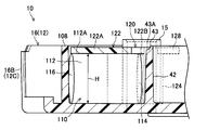
- the security tag 110 is installed in the installation space 100 so that the axis P (indicated by a virtual line in FIG. 5) is not perpendicular to the bottom plate 16A of the lower case 16. More specifically, as shown in FIG. 4, the security tag 110 is placed horizontally in the installation space 100 so that the axis P is substantially parallel to the bottom plate 16 ⁇ / b> A of the lower case 16.
- the security tag 110 has a plan view shown in FIG. 4 (viewed from the axial direction of the reel 20) so that the axis P is not perpendicular to the peripheral wall 16B of the lower case 16 (the axis P is the case). 12 front walls 12A and the left wall 12C).
- the security tag 110 may be held by the resin holding member 120 shown in FIGS. 6 to 12 and fixed for each recording tape cartridge 10 so that the position of the security tag 110 does not fluctuate.
- the holding member 120 has a holding portion 122 that holds the security tag 110 on one end side, and a fitting portion 124 that is attached to the case 12 (lower case 16) on the other end side.
- the fitting portion 124 is formed in a cylindrical shape that is inserted (fitted) by press-fitting into the screw boss 15 as a fitted portion protruding from the inner surface of the bottom plate 16A of the lower case 16 from above. That is, as shown in detail in FIGS. 6 to 9, a part of the inner peripheral surface of the fitting portion 124 has a substantially flat projecting shape in which the upper side protrudes more radially inward than the lower side. A portion 126 is formed, and the protruding portion 126 is configured such that the inner diameter of a part of the fitting portion 124 is smaller than the inner diameter of other portions.
- the screw boss 15 is configured to be press-fitted into the fitting portion 124 (fitted with resistance) by the overhanging portion 126, and thereby, the fitting portion 124 is detached from the screw boss 15 ( (Upward movement) is prevented, and rotation of the fitting portion 124 (holding member 120) around the screw boss 15 is suppressed or prevented.
- the holding unit 122 moves the security tag 110 disposed in the installation space 100 of the lower case 16 to the upper side (axial direction of the reel 20) and the lateral side (direction orthogonal to the axial direction of the reel 20: hereinafter “horizontal direction”. And a flat wall portion that can be pressed and held.
- the holding portion 122 is integrally extended from the upper end portion of the outer peripheral surface of the fitting portion 124 into a wide “J” shape in a plan view and faces downward.
- the flat pressing portion 122 ⁇ / b> A having a wall surface is integrated with the bottom of the pressing portion 122 ⁇ / b> A and from the outer peripheral surface of the fitting portion 124 in a substantially “L” shape in a bottom view ( And a flat plate-like pressing portion 122B having a wall surface facing the horizontal direction.
- the length D in the extending direction of the pressing portion 122A is preferably longer than the radius of the security tag 110, but may be shorter than the diameter.
- the width W orthogonal to the length D of the pressing portion 122A may be shorter than the length of the security tag 110.
- the width W of the pressing portion 122B may be shorter than the length of the security tag 110, but the height H of the pressing portion 122B is substantially the same as the diameter of the security tag 110 as shown in FIG. It is desirable.
- a tongue-shaped rib 128 (tip is arc-shaped) as an engaging portion is integrally projected from the outer peripheral surface of the fitting portion 124 and on the upper end portion on the side opposite to the pressing portion 122A.
- the rib 128 is formed on the outer peripheral surface 42A of the floating regulation wall 42 as a locked portion in the installation space 100. It is designed to be locked.
- the retaining member 120 is centered on the screw boss 15 by a reaction caused by the rib 128 pressing the outer peripheral surface 42A of the play restricting wall 42.
- a biasing force in the direction of arrow F shown in FIG. 11
- the security tag 110 can be pressed by its urging force, thereby disabling the rotation of the holding member 120 around the screw boss 15 (fixing the holding member 120). it can.
- the security tag 110 is placed horizontally in the installation space 100 in the left front corner portion of the lower case 16 (the axis P is perpendicular to the axial direction of the reel 20). Placed to face). Therefore, when the fitting portion 124 of the holding member 120 is inserted into the screw boss 15, the pressing portion 122 ⁇ / b> A of the holding portion 122 presses the upper surface portion 112 ⁇ / b> A of the peripheral surface 112 of the security tag 110 from above, and the security tag 110. Restricts upward movement (height direction).
- the pressing portion 122B of the holding portion 122 presses the side surface portion 112B on the peripheral surface 112 of the security tag 110 from the lateral side by the urging force, and a part of the side surface portion 112C opposite to the side surface portion 112B is 180 °.
- the peripheral portion (a part) of one bottom surface 114 of the security tag 110 is placed on the outer peripheral surface 42A of the floating regulation wall 42 as the second wall portion in the installation space 100. The movement of the security tag 110 in the horizontal direction is restricted.
- the security tag 110 has one point (actually a line along the axial direction of the security tag 110) by the holding portion 122A of the holding portion 122 and the holding portion 122 in a plan view (viewed from the axial direction of the reel 20). Are held at three points (actually lines and surfaces) by the pressing portion 122B, the bag portion 105, and the floating regulation wall 42, thereby preventing the floating in the installation space 100.
- the security tag 110 is prevented from being damaged due to its play and is positioned and held in the installation space 100 of the case 12 with high accuracy.
- a gap may be formed between the other bottom surface 116 of the security tag 110 and the inner surface of the standing wall 108, or a gap may not be formed.
- the upper surface (the pressing portion 122A and the rib 128) of the holding member 120 and the security tag 110 are shown in FIG. As described above, so as not to protrude upward from the front end surface (upper end surface) of each wall portion such as the peripheral wall 16B, the floating regulation wall 42, the overhanging wall portion 107, and the standing wall 108 constituting the installation space 100 of the lower case 16. That is, the dimensions are appropriately determined so as to be arranged at a position (lower position) lower than the respective front end faces in a side view.
- the holding member 120 and the security tag 110 are attached to the peripheral wall 14 ⁇ / b> B of the upper case 14 on the upper side of the installation space 100, the floating regulation wall 42, and the like. There is no risk of interference. That is, there is no possibility that the holding member 120 and the security tag 110 are bitten between the upper case 14 and the lower case 16.
- stepped portions 43 are respectively formed at the leading ends of the floating regulation wall 42 of the upper case 14 and the floating regulation wall 42 of the lower case 16, and the upper regulation case 42 is covered with the lower case 16 so that the floating regulation walls 42 abut each other.
- the upper surface of the holding member 120 and the security tag 110 rather than the abutting surface 43A that is the lower end surface of the stepped portion 43. It is desirable that the dimensions are appropriately determined so that the position is low (low).
- holding in the present embodiment means that movement in at least two directions, that is, the upward direction and the horizontal direction is restricted.
- the resin material for forming the holding member 120 include polyethylene (PE), polypropylene (PP), polystyrene (PS), polyacetal (POM), and polycarbonate (PC).
- a gate mark G is formed at the tip of the rib 128 at the approximate center in the height direction. That is, the gate of the resin material when the holding member 120 is molded is the tip of the rib 128.
- the rib 128 is locked to the floating regulation wall 42 and has a function of preventing the holding member 120 from rotating, and therefore requires a certain degree of rigidity and is formed thick. Therefore, if the tip of the rib 128 is used as a gate position and a resin material is injected therefrom, it is easy to transmit the resin pressure when the holding member 120 is molded, and the dimensional accuracy of the holding member 120 can be improved.
- the opening 18 of the recording tape cartridge 10 is closed by a door 50 when not in use (during storage or transportation).
- the braking member 80 is positioned at the rotation lock position by the urging force of the compression coil spring 98, and the braking gear 84 is engaged with the engaging gear 48. For this reason, the reel 20 is prevented from rotating with respect to the case 12.
- the recording tape cartridge 10 is loaded into the drive device along the arrow A direction with the front wall 12A at the head. Then, first, the opening / closing member provided on the drive device side engages with the convex portion 56 of the door 50. In this state, when the recording tape cartridge 10 further moves in the arrow A direction, the opening / closing member moves the projection 56 relatively rearward against the urging force of the coil spring 58.
- the door 50 on which the convex portion 56 projects is slid rearward in the groove portion 64 along the right wall 12B, and the opening 18 is opened.
- the position restricting member provided in the drive device engages with the recess 106 formed in the front wall 12A of the case 12 (lower case 16). Thereby, the position (depth) in the loading direction of the recording tape cartridge 10 is regulated.
- the recording tape cartridge 10 when the recording tape cartridge 10 is loaded into the drive device at a predetermined depth and the opening 18 is completely opened, the recording tape cartridge 10 is lowered by a predetermined height, and the positioning member of the drive device is formed on the lower case 16. Are inserted into the positioning holes 102 and 104. Thus, the recording tape cartridge 10 is accurately positioned at a predetermined position in the drive device, and further sliding (rearward movement) of the door 50 is restricted.
- the rotary shaft relatively enters from the gear opening 40, and the drive gear is engaged with the reel gear 44. Then, as the drive gear meshes with the reel gear 44, the leg portion 94 protruding on the reel gear 44 is pushed up against the urging force of the compression coil spring 98, and the braking member is interposed via the release member 90. 80 is pushed upward, and the meshing between the brake gear 84 and the engagement gear 48 is released.
- the reel plate 46 is attracted and held by the magnetic force of the annular magnet provided on the radially inner side of the drive gear, so that the reel 20 is driven. While the meshing of the reel gear 44 with the gear is maintained, the unlocked state in which the relative rotation with respect to the case 12 is possible is made in the case 12.
- a drawing member provided on the drive device side enters the case 12, and grips and pulls out the leader pin 30 positioned and held by the pin holding portion 36.
- the drawing member can reliably engage the hook with the annular groove 32 of the leader pin 30. Further, since the rotation lock state of the reel 20 is released, the reel 20 can rotate as the leader pin 30 is pulled out.
- the leader pin 30 extracted from the opening 18 is accommodated in a take-up reel (not shown). Then, by rotating the take-up reel and the reel 20 synchronously, the recording tape T is sequentially drawn out from the case 12 while being taken up by the take-up reel, and is arranged along a predetermined tape path. Information is recorded or reproduced by a recording / reproducing head (not shown).
- the recording tape cartridge 10 that has finished recording and reproducing information is ejected from the drive device, first, the recording tape T is rewound onto the reel 20 by the reverse rotation of the rotating shaft.
- the recording tape cartridge 10 rises by a predetermined height, and the positioning member becomes the positioning hole 102. , 104 and the rotating shaft is extracted from the gear opening 40, and the engagement of the drive gear with the reel gear 44 is released.
- the braking member 80 and the release member 90 are pressed downward by the urging force of the compression coil spring 98, and the leg portion 94 is inserted into the through hole 28A so as to reach a predetermined height on the reel gear 44 from the lower surface of the bottom wall 28.
- the brake gear 84 meshes with the engagement gear 48 while projecting.
- the reel 20 is again in a rotation-locked state in which relative rotation in the case 12 is prevented, and then the recording tape cartridge 10 is moved in the direction opposite to the arrow A direction by an unillustrated ejecting mechanism.
- the door 50 slides in the closing direction of the opening 18 by the biasing force of the coil spring 58 and completely closes the opening 18 (returns to the initial state).
- the relative rotation of the reel 20 with respect to the case 12 is locked, and the recording tape cartridge 10 with the opening 18 closed is completely ejected from the drive device.
- the security tag 110 is installed so that the axis P is not perpendicular to the bottom plate 16A of the lower case 16. More specifically, the security tag 110 is placed horizontally such that the axis P is substantially parallel to the bottom plate 16 ⁇ / b> A of the lower case 16.
- each security tag 110 does not overlap, Magnetic coupling does not occur in the security tag 110. Therefore, in each security tag 110, communication performance does not deteriorate.
- the security tag 110 has an axis P that is not perpendicular to the peripheral wall 16B of the lower case 16 in plan view (the axis P is not orthogonal to the front wall 12A and the left wall 12C of the case 12). Like).
- the security tag 110 is pressed from above by the pressing portion 122A of the holding portion 122 in a state where the fitting portion 124 of the holding member 120 is press-fitted (fitted) to the screw boss 15 and is also configured to restrict free movement. Since the rib 128 is locked to the wall 42, it is pressed from the side by the pressing portion 122B of the holding portion 122 biased in the direction of arrow F (see FIG. 11) (the bag portion 105 and the floating regulation wall 42). )
- the security tag 110 is restricted from moving in the upward and horizontal directions by the holding member 120 that is prevented from rotating around the screw boss 15, and in this state, the lower case 16 It is positioned and held (fixed) in the installation space 100. Therefore, the security tag 110 does not move in the installation space 100, and damage due to the movement is prevented.
- the screw boss 15 and the bag portion 105 are portions having high dimensional accuracy due to the structure of the recording tape cartridge 10. Therefore, by inserting (fitting) the fitting portion 124 of the holding member 120 into the screw boss 15 and pressing the security tag 110 against the bag portion 105 by the pressing portion 122 ⁇ / b> B of the holding portion 122, the security tag 110 in the case 12. Can be accurately stabilized.
- the fitting portion 124 of the holding member 120 is structured to be fitted (press-fitted) from above into the screw boss 15 protruding from the inner surface of the bottom plate 16 ⁇ / b> A of the lower case 16, and the holding portion of the holding member 120.
- 122 also has a structure in which the security tag 110 is pressed from the upper side (upper surface portion 112A side) and the lateral side (side surface portion 112B side) facing the screw boss 15.
- the holding member 120 is mounted from above, which is the fitting direction of the fitting portion 124, so as to hold the security tag 110 in a state where the security tag 110 is placed in the installation space 100 of the lower case 16. be able to. Therefore, it is possible to improve the incorporation of the security tag 110 and the holding member 120 into the case 12 (in the installation space 100 of the lower case 16).
- the upper surface (holding portion 122A and rib 128) of the holding member 120 is a front end surface (upper surface) of each wall portion such as the peripheral wall 16B, the floating regulation wall 42, the overhang wall portion 107, and the standing wall 108 of the lower case 16 in a side view. Since the case 12 is assembled, the holding member 120 and the security tag 110 are not likely to be bitten between the upper case 14 and the lower case 16. Therefore, the assembling property of the recording tape cartridge 10 (case 12) can be improved, and the communication performance of the security tag 110 can be prevented from being adversely affected.
- the pressing portion 122A and the pressing portion 122B of the holding portion 122 are in contact with the peripheral surface 112 of the security tag 110 only from two directions orthogonal to each other (only the upper surface portion 112A and the side surface portion 112B). Therefore, even if the size (length or diameter) of the security tag 110 is changed to improve communication performance, it is possible to cope with the design change. That is, since the holding member 120 has few restrictions on the dimensional shape of the security tag 110, the degree of freedom in designing the security tag 110 can be improved.
- the holding portion 122 covers only the upper surface portion 112A and the side surface portion 112B on the peripheral surface 112 of the security tag 110, and does not cover other portions.
- the resin material used is smaller than that of the storage container. Therefore, the manufacturing cost of the holding member 120 itself can be reduced, and as a result, the manufacturing cost of the recording tape cartridge 10 can be reduced.
- the holding portion 122 (the holding portion 122A and the pressing portion 122B) is attached to the security tag 110.
- the peripheral surface 112 (the upper surface portion 112A and the side surface portion 112B) can be reliably brought into contact (pressure contact). Therefore, the assembling property (mounting property) of the holding member 120 with respect to the security tag 110 is not impaired.
- the holding member 120 is configured to fix the security tag 110 in cooperation with the case 12. Specifically, the holding member 120 is pressed against the lower case 16 by pressing the security tag 110 toward the bag portion 105 and the play regulation wall 42. For example, even if the size of the installation space 100 at the left front corner of the lower case 16 is changed, the security tag 110 can be positioned as long as the screw boss 15, the bag portion 105, and the floating regulation wall 42 are provided. Can be held. That is, according to the holding member 120 having such a configuration, the security tag 110 can be held in the case 12 without being affected by the design change of the case 12.
- the holding member 120 that holds the security tag 110 is provided separately from the case 12, it is necessary to form a holding structure for holding the security tag 110 in the case 12 (upper case 14 and lower case 16). There is no. Therefore, it is not necessary to change the design of the mold for injection molding the case 12 (the upper case 14 and the lower case 16), thereby preventing an increase in manufacturing cost.
- the recording tape cartridge 10 according to the present embodiment has been described above.
- the recording tape cartridge 10 according to the present embodiment is not limited to the illustrated examples, and may be appropriately selected within the scope not departing from the gist of the present invention.
- the design can be changed.
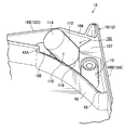
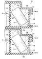
- the security tag 110 has an axis P (shown by an imaginary line in FIG. 15) that is inclined with respect to the vertical direction in a side view (the bottom case 16 It may be configured to be installed in the installation space 100 (so as not to be perpendicular to the bottom plate 16A).
- the length of the security tag 110 is made longer than that shown in FIGS. 4 and 5, and the peripheral portion of the other bottom surface 116 (one Part) and a part of the peripheral surface 112 of the bottom surface 114 or a part of the peripheral surface 112 may be supported by the floating regulation wall 42.
- the security tag 110 (axial center P) is held obliquely with respect to the vertical direction when viewed from the side, the length can be made longer than that shown in FIGS. Even if the case 12 of the recording tape cartridge 10 is stacked in the vertical direction (height direction) on the case 12 of another recording tape cartridge 10 as shown in FIG. It is possible to prevent the axis P of the tag 110 from overlapping.
- the case 12 of the recording tape cartridge 10 is arranged next to the case 12 of the other recording tape cartridge 10 with the front wall 12A and the rear wall 12D or the left wall 12C and the right wall 12B aligned.
- the axis P of each security tag 110 does not overlap.
- the axis P is not perpendicular to the peripheral wall 16 ⁇ / b> B of the lower case 16 (so that the axis P is not orthogonal to the front wall 12 ⁇ / b> A and the left wall 12 ⁇ / b> C of the case 12). It is preferable to install.
- the security tag 110 that is inclined in this way may be configured to be held by appropriately changing the shape of the holding member 120.
- the pressing portion 122B of the holding portion 122 that presses the security tag 110 from the side (horizontal direction) in cooperation with the case 12 is not limited to the illustrated one point (surface), but two points (surface). It may be set as above.
- the fitted portion is not limited to the screw boss 15 but may be a protruding portion (not shown) or the like that protrudes in a convex shape on the inner surface of the bottom plate 16A of the lower case 16.
- the recording tape cartridge 10 may be visually determined that the recording tape cartridge 10 has the security tag 110 built therein. That is, for example, characters such as “Security” are printed on the top surface of the case 12 (the outer surface of the top plate 14A of the upper case 14), or a concave portion for identification (illustrated on the bottom surface of the bottom plate 16A of the lower case 16). (Omitted) etc. may be formed.
- the installation space 100 may be formed not on the lower case 16 side but on the upper case 14 side. That is, the security tag 110 and the holding member 120 may be provided on the upper case 14 side.
- the recording tape cartridge 10 for data backup in which the reel 20 is accommodated in the case 12 is described.
- the recording tape cassette for video tape in which two reels are accommodated in the case. The present invention can also be applied to the above.
- the recording tape T wound around the reel 20 only needs to be understood as a long tape-like information recording / reproducing medium capable of recording information and reproducing the recorded information, and accommodates the reel 20.
- the recording tape cartridge 10 can be applied to the recording tape T of any recording / reproducing system.
- Japanese Patent Application No. The disclosure of 2010-59947 is hereby incorporated by reference in its entirety.
Landscapes
- Packaging Of Annular Or Rod-Shaped Articles, Wearing Apparel, Cassettes, Or The Like (AREA)
Abstract
Description
12 ケース
14 上ケース
15 ビスボス(被嵌合部)
16 下ケース
16A 底板
16B 周壁
20 リール
30 リーダーピン
42 遊動規制壁
100 設置スペース
105 袋部
108 立壁
110 セキュリティータグ
112 周面
114 底面
116 底面
120 保持部材
122 保持部
122A 押さえ部
122B 押圧部
124 嵌合部
126 張出部
128 リブ
P 軸心
T 記録テープ
Claims (7)
- 記録テープが巻装されたリールを収容するケースと、
前記ケース内に設けられ、外部と送受信可能なセキュリティータグと、
を有する記録テープカートリッジであって、
前記セキュリティータグは、
磁性コアの外周面に線材が巻回されて形成されたコイルを備えた柱状とされ、
前記ケースを他の記録テープカートリッジのケースに積み重ねた場合に、他の記録テープカートリッジのケース内のセキュリティータグと軸心が重ならないように、前記ケース内に設置されている記録テープカートリッジ。 - 前記セキュリティータグは、軸心が前記ケースの底板に対して垂直にならないように設置されている請求項1に記載の記録テープカートリッジ。
- 前記セキュリティータグは、軸心が前記ケースの底板に対して略平行になるように設置されている請求項1又は請求項2に記載の記録テープカートリッジ。
- 前記セキュリティータグは、前記リールの軸方向から見て、軸心が前記ケースの周壁に対して垂直にならないように設置されている請求項1~請求項3の何れか1項に記載の記録テープカートリッジ。
- 前記ケース内に設けられ、前記セキュリティータグを前記リールの軸方向と、該軸方向と直交する方向とから前記ケースと協働して保持する保持部が一端側に形成された保持部材と、
前記ケース内に形成され、前記保持部材の他端側に形成された嵌合部が嵌合された被嵌合部と、
を有する請求項1~請求項4の何れか1項に記載の記録テープカートリッジ。 - 前記保持部材は、前記ケース内に前記セキュリティータグが設けられた状態で、前記ケース内に装着可能に形成されている請求項5に記載の記録テープカートリッジ。
- 記録テープが巻装されたリールを収容する略矩形状のケースと、
前記ケース内に設けられ、外部と送受信可能なセキュリティータグと、
を有する記録テープカートリッジであって、
前記セキュリティータグは、
磁性コアの外周面に線材が巻回されて形成されたコイルを備えた柱状とされ、
前記ケースを他の記録テープカートリッジのケースの隣に前後又は左右の周壁を揃えて並べた場合に、他の記録テープカートリッジのケース内のセキュリティータグと軸心が重ならないように、前記ケース内に設置されている記録テープカートリッジ。
Priority Applications (2)
| Application Number | Priority Date | Filing Date | Title |
|---|---|---|---|
| US13/634,241 US20130003275A1 (en) | 2010-03-16 | 2011-02-04 | Recording tape cartridge |
| CN2011800141023A CN102804272A (zh) | 2010-03-16 | 2011-02-04 | 记录带盒 |
Applications Claiming Priority (2)
| Application Number | Priority Date | Filing Date | Title |
|---|---|---|---|
| JP2010-059947 | 2010-03-16 | ||
| JP2010059947A JP5479172B2 (ja) | 2010-03-16 | 2010-03-16 | 記録テープカートリッジ |
Publications (1)
| Publication Number | Publication Date |
|---|---|
| WO2011114796A1 true WO2011114796A1 (ja) | 2011-09-22 |
Family
ID=44648903
Family Applications (1)
| Application Number | Title | Priority Date | Filing Date |
|---|---|---|---|
| PCT/JP2011/052432 Ceased WO2011114796A1 (ja) | 2010-03-16 | 2011-02-04 | 記録テープカートリッジ |
Country Status (4)
| Country | Link |
|---|---|
| US (1) | US20130003275A1 (ja) |
| JP (1) | JP5479172B2 (ja) |
| CN (1) | CN102804272A (ja) |
| WO (1) | WO2011114796A1 (ja) |
Families Citing this family (1)
| Publication number | Priority date | Publication date | Assignee | Title |
|---|---|---|---|---|
| JP6534359B2 (ja) * | 2016-03-30 | 2019-06-26 | 富士フイルム株式会社 | 磁気テープカートリッジ |
Citations (5)
| Publication number | Priority date | Publication date | Assignee | Title |
|---|---|---|---|---|
| JPH0714346A (ja) * | 1993-06-25 | 1995-01-17 | Sony Corp | テープカセットのic基板取付構造 |
| JPH0714347A (ja) * | 1993-06-25 | 1995-01-17 | Sony Corp | テープカセットのic基板取付構造 |
| JP2007004938A (ja) * | 2005-06-27 | 2007-01-11 | Fujifilm Holdings Corp | 磁気テープカートリッジ |
| JP2008090942A (ja) * | 2006-10-03 | 2008-04-17 | Tdk Corp | カートリッジケースおよび情報記録媒体 |
| JP2009129531A (ja) * | 2007-11-28 | 2009-06-11 | Tdk Corp | カートリッジケースおよび情報記録媒体 |
Family Cites Families (18)
| Publication number | Priority date | Publication date | Assignee | Title |
|---|---|---|---|---|
| US4692746A (en) * | 1986-02-26 | 1987-09-08 | Security Tag Systems, Inc. | Recording-tape-reel assembly with electronic tag |
| US5636096A (en) * | 1995-10-02 | 1997-06-03 | Aris Mardirossian, Inc. | Magnetic disc cartridge and corresponding system/method for limiting copying of software |
| JP3438565B2 (ja) * | 1997-08-22 | 2003-08-18 | ユニ電子工業株式会社 | 盗難防止用タグ |
| JP2002050154A (ja) * | 2000-08-03 | 2002-02-15 | Fuji Photo Film Co Ltd | 記録媒体カートリッジ |
| JP2002140879A (ja) * | 2000-11-02 | 2002-05-17 | Sony Corp | 情報記憶カートリッジ |
| JP2003157655A (ja) * | 2001-11-20 | 2003-05-30 | Fuji Photo Film Co Ltd | 記録テープカートリッジ |
| US6702215B2 (en) * | 2002-07-03 | 2004-03-09 | Quantum Corporation | Repositionable memory element in a single reel tape cartridge |
| US7315253B1 (en) * | 2002-07-04 | 2008-01-01 | Meadwestvaco Corporation | Security device and transponder |
| CN1926721A (zh) * | 2004-03-24 | 2007-03-07 | 株式会社内田洋行 | 记录介质用ic标签粘贴片及记录介质 |
| US7262699B2 (en) * | 2004-12-30 | 2007-08-28 | Alpha Security Products, Inc. | Security device for cylindrical merchandise |
| US20080278335A1 (en) * | 2007-05-08 | 2008-11-13 | Welte Gregory A | Automated pet entry door |
| JP4875017B2 (ja) * | 2008-03-31 | 2012-02-15 | 富士フイルム株式会社 | 記録テープカートリッジ |
| JP4902583B2 (ja) * | 2008-03-31 | 2012-03-21 | 富士フイルム株式会社 | 記録テープカートリッジ |
| JP4864928B2 (ja) * | 2008-03-31 | 2012-02-01 | 富士フイルム株式会社 | 記録テープカートリッジ |
| JP2010015230A (ja) * | 2008-07-01 | 2010-01-21 | Actuni Co Ltd | セキュリティタグ、セキュリティシステム、及びアンテナ装置 |
| JP5137925B2 (ja) * | 2009-09-28 | 2013-02-06 | 富士フイルム株式会社 | 記録テープカートリッジ |
| JP2011090757A (ja) * | 2009-09-28 | 2011-05-06 | Fujifilm Corp | 記録テープカートリッジ |
| JP5430455B2 (ja) * | 2010-03-15 | 2014-02-26 | 富士フイルム株式会社 | 記録テープカートリッジ |
-
2010
- 2010-03-16 JP JP2010059947A patent/JP5479172B2/ja active Active
-
2011
- 2011-02-04 WO PCT/JP2011/052432 patent/WO2011114796A1/ja not_active Ceased
- 2011-02-04 CN CN2011800141023A patent/CN102804272A/zh active Pending
- 2011-02-04 US US13/634,241 patent/US20130003275A1/en not_active Abandoned
Patent Citations (5)
| Publication number | Priority date | Publication date | Assignee | Title |
|---|---|---|---|---|
| JPH0714346A (ja) * | 1993-06-25 | 1995-01-17 | Sony Corp | テープカセットのic基板取付構造 |
| JPH0714347A (ja) * | 1993-06-25 | 1995-01-17 | Sony Corp | テープカセットのic基板取付構造 |
| JP2007004938A (ja) * | 2005-06-27 | 2007-01-11 | Fujifilm Holdings Corp | 磁気テープカートリッジ |
| JP2008090942A (ja) * | 2006-10-03 | 2008-04-17 | Tdk Corp | カートリッジケースおよび情報記録媒体 |
| JP2009129531A (ja) * | 2007-11-28 | 2009-06-11 | Tdk Corp | カートリッジケースおよび情報記録媒体 |
Also Published As
| Publication number | Publication date |
|---|---|
| JP2011192367A (ja) | 2011-09-29 |
| US20130003275A1 (en) | 2013-01-03 |
| JP5479172B2 (ja) | 2014-04-23 |
| CN102804272A (zh) | 2012-11-28 |
Similar Documents
| Publication | Publication Date | Title |
|---|---|---|
| US7770835B2 (en) | Recording tape cartridge | |
| JP5137925B2 (ja) | 記録テープカートリッジ | |
| JP5430457B2 (ja) | 記録テープカートリッジ | |
| US8561931B2 (en) | Recording tape cartridge | |
| JP5479172B2 (ja) | 記録テープカートリッジ | |
| US7562839B2 (en) | Recording tape cartridge | |
| US20110273801A1 (en) | Packing method for recording tape cartridges and package of recording tape cartridges | |
| JP2011192365A (ja) | 記録テープカートリッジ | |
| JP4864921B2 (ja) | 記録テープカートリッジ | |
| JP2011070747A (ja) | 記録テープカートリッジ | |
| JP5026453B2 (ja) | リール及び記録テープカートリッジ | |
| JP4819011B2 (ja) | 記録テープカートリッジ | |
| JP2011070748A (ja) | 記録テープカートリッジ | |
| WO2011102182A1 (ja) | 記録テープカートリッジ | |
| JP4902584B2 (ja) | 記録テープカートリッジ | |
| JP2010067318A (ja) | 記録テープカートリッジ | |
| JP4875013B2 (ja) | リールの製造方法及びリール | |
| JP2017182853A (ja) | 磁気テープカートリッジ | |
| WO2010103923A1 (ja) | 記録テープカートリッジ | |
| JP2010211873A (ja) | 記録テープカートリッジ | |
| JP2010061745A (ja) | 記録メディアカートリッジ | |
| JP2007052829A (ja) | リール及び記録テープカートリッジ | |
| WO2010103924A1 (ja) | 記録テープカートリッジ及びセキュリティー用認識部材の製造方法 | |
| JP2010067290A (ja) | 記録テープカートリッジ | |
| JP2010073253A (ja) | 記録テープカートリッジ |
Legal Events
| Date | Code | Title | Description |
|---|---|---|---|
| WWE | Wipo information: entry into national phase |
Ref document number: 201180014102.3 Country of ref document: CN |
|
| 121 | Ep: the epo has been informed by wipo that ep was designated in this application |
Ref document number: 11755986 Country of ref document: EP Kind code of ref document: A1 |
|
| WWE | Wipo information: entry into national phase |
Ref document number: 13634241 Country of ref document: US |
|
| NENP | Non-entry into the national phase |
Ref country code: DE |
|
| 122 | Ep: pct application non-entry in european phase |
Ref document number: 11755986 Country of ref document: EP Kind code of ref document: A1 |