WO2011114596A1 - 交通信号制御システム及び交通信号制御装置並びに交通信号制御方法 - Google Patents
交通信号制御システム及び交通信号制御装置並びに交通信号制御方法 Download PDFInfo
- Publication number
- WO2011114596A1 WO2011114596A1 PCT/JP2010/072961 JP2010072961W WO2011114596A1 WO 2011114596 A1 WO2011114596 A1 WO 2011114596A1 JP 2010072961 W JP2010072961 W JP 2010072961W WO 2011114596 A1 WO2011114596 A1 WO 2011114596A1
- Authority
- WO
- WIPO (PCT)
- Prior art keywords
- time
- traffic signal
- signal control
- switching table
- pattern switching
- Prior art date
- Legal status (The legal status is an assumption and is not a legal conclusion. Google has not performed a legal analysis and makes no representation as to the accuracy of the status listed.)
- Ceased
Links
Images





Classifications
-
- G—PHYSICS
- G08—SIGNALLING
- G08G—TRAFFIC CONTROL SYSTEMS
- G08G1/00—Traffic control systems for road vehicles
- G08G1/07—Controlling traffic signals
Definitions
- the present invention relates to a traffic signal control system for upgrading a pattern selection type traffic signal control system according to time using travel time information.
- a traffic signal control method (time control pattern selection method) in which a plurality of signal control parameters are stored for each time zone, and traffic signal control is performed by selecting the stored signal control parameters according to time.
- traffic signal control method time control pattern selection method
- the traffic demand for each time zone is grasped in advance before the operation is started, the demand is patterned according to time, and signal control parameters suitable for each demand pattern are stored.
- the traffic signal control is performed by selecting the stored signal control parameter according to the grasped traffic situation pattern.
- a traffic signal control method pattern selection method based on travel time
- These pattern-selection-type traffic signal control methods can be introduced more easily than the method of calculating the sequential signal control parameters according to the traffic volume and congestion length, and any one of a plurality of stored patterns Therefore, there is an advantage that there is no fear of an unexpected control method compared to the case of sequential calculation.
- a pattern selection method based on travel time for example, an erroneous travel time obtained by a vehicle sensor that has caused a malfunction, or a travel time with high uncertainty obtained by a small number of probe information.
- a signal control parameter that does not match the actual traffic situation is selected based on the system, and there is room for improvement in a system that selects a pattern based only on travel time for stable operation of the system.
- time control pattern selection method there is no problem as long as traffic signal control is performed in an area where there is almost no change in the traffic demand assumed in advance, but the time when congestion starts and the time when congestion begins to disappear In regions where there are variations, there are cases where the pattern selected in that time zone does not match the actual traffic situation, and there is room for improvement in the method of selecting a pattern based only on the time.
- the present invention has been made in view of such circumstances, and is appropriate even in cases where there is an error or uncertainty in the traffic information such as travel time obtained or the traffic demand that is assumed in advance is likely to fluctuate. It is an object of the present invention to provide a traffic signal control system that operates in an automatic manner.
- the traffic signal control system is a traffic signal control parameter associated with each first time zone B1 (i) of the first time schedule obtained by dividing the entire time zone of the day into a plurality of first time zones.
- Storage means for storing a first pattern switching table in which P1 (i) is set, selection means for selecting a traffic signal control parameter corresponding to the current time from the stored first pattern switching table, and the selected traffic Control means for controlling the traffic signal lamp using the signal control parameter, and travel time acquisition means for acquiring travel time information of vehicles in one or a plurality of road sections in the vicinity of the traffic signal lamp.
- the second condition relating to the travel time in the second time zone T2 composed of only a part of the entire time zone of the day and the traffic selected when the second condition is met.
- the selection means replaces the traffic signal control parameter P1 (i) with the second pattern switching table.
- the set traffic signal control parameter P2 is selected (claim 1).
- i is an integer from 1 to m
- m is the number of time zones defined in the first pattern switching table.
- the travel time is based on the travel time in the specific time zone (second time zone T2).
- second time zone T2 different traffic signal control parameters can be selected.
- This makes it possible to select traffic signal control parameters that appear to be more appropriate based on travel time information in a specific time zone, and therefore adapts to traffic conditions rather than simple time control pattern selection methods. It is possible to perform traffic signal control.
- this system is based on selecting the pattern according to the time of day, so in most time zones, compared to the method of selecting the signal control parameter only according to the travel time, it is necessary to have advanced traffic management in advance.
- the traffic signal control parameters set by the user can be selected, so even if the travel time information acquired by the vehicle detector etc. is different from the actual traffic situation, most of the time It is possible to perform an appropriate operation in the band, and the robustness of the system is increased.
- the end time of the second time zone T2 is set to the end time of the first time zone B1 (k) of the first time zones included in the first time schedule, and the second time zone Is set to a time later than the start time of the first first time zone B1 (k), and then the traffic signal is set in association with the second time zone T2 in the second pattern switching table.
- the traffic signal control parameter P1 (k + 1) set in the first pattern switching table in association with the subsequent first time zone B1 (k + 1) following the one first time zone B1 (k) (Claim 2).
- the first pattern switching table is set based on the prior prediction that the traffic situation changes at the end time of the first time zone B1 (k) (that is, the start time of B1 (k + 1)).
- the traffic signal control parameter P1 (k + 1) in B1 (k + 1) can be selected ahead of schedule. Flexible operation is possible.
- the start time of the second time zone T2 is set to the start time of one first time zone B1 (k) of the first time zones included in the first time schedule, and the second time zone T2 Traffic signal control set in association with the second time zone T2 in the second pattern switching table after setting the end time to a time before the end time of the first first time zone B1 (k)
- the parameter P2 is associated with the first time zone B1 (k-1) immediately before the first first time zone B1 (k), and the traffic signal control parameter P1 ( k-1) (Claim 3).
- the first pattern switching table is set based on the prior prediction that the traffic situation changes at the start time of the first time zone B1 (k) (that is, the end time of B1 (k-1)). If the traffic situation changes at a later stage than the previous prediction, the traffic signal control parameter P1 (k-1) in B1 (k-1) can be extended without switching the pattern at a rapid speed. Therefore, it becomes possible to operate more flexibly than the time control pattern selection method.
- the selection unit determines at the determination execution time.
- the travel time acquired by the travel time acquisition means may fluctuate temporarily due to, for example, the fact that one vehicle is stuck on the road for some reason. Will soon return to normal. Therefore, in the second time zone T2, for example, an index based on travel time is calculated a plurality of times with a period of, for example, 10 minutes or 15 minutes, and temporarily changes, but when the first pattern switching table is set immediately, When returning to the expected traffic situation, the traffic signal control parameters set in the first pattern switching table can be restored. As described above, by allowing the first pattern switching table and the second pattern switching table to be moved back and forth flexibly, it becomes possible to perform traffic signal control more suitable for traffic conditions.
- the travel time is acquired by the travel time acquisition means based on probe information which is travel locus information transmitted from onboard devices mounted on a plurality of public vehicles including the traffic signal lamp installation point on the route.
- probe information which is travel locus information transmitted from onboard devices mounted on a plurality of public vehicles including the traffic signal lamp installation point on the route.
- the predetermined time be longer than a time interval in which the plurality of public vehicles pass through the traffic signal lamp installation point (Claim 5).
- probe information obtained from a public vehicle such as a bus that a professional driver repeatedly travels the same route than when using probe information from an unspecified vehicle. Because it is difficult to be affected by the nature of the driver and the installation rate of the in-vehicle device, it is easy to accurately grasp fluctuations in traffic conditions for each time zone.
- a traffic signal control device including all the means used in the traffic signal control system and a traffic signal control method (claim 7) executed by the traffic signal control system are also very useful.
- the traffic signal control adapted to the traffic situation can be performed by utilizing the advantages of both the time control pattern selection method and the travel time pattern selection method. Is possible.
- FIG. 1 is a schematic diagram showing an outline of a traffic signal control system according to the present invention.
- FIG. 2 is a block diagram showing an example of the configuration of the traffic signal controller 1a.
- FIG. 3 is a block diagram illustrating an example of the configuration of the communication control device 21b of the road communication device 21.
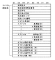
- FIG. 4 is a diagram showing a format of signal control command information.
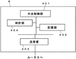
- FIG. 5 is a block diagram illustrating an example of the configuration of the central device 4.
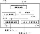
- FIG. 6 is a block diagram illustrating an example of the configuration of the in-vehicle device 31 mounted on the vehicle.
- FIG. 7 is a diagram illustrating an example of a traffic signal control parameter table used in traffic signal control.
- FIG. 1 is a schematic diagram showing an outline of a traffic signal control system according to the present invention.
- FIG. 2 is a block diagram showing an example of the configuration of the traffic signal controller 1a.
- FIG. 3 is a block diagram illustrating an example of the configuration of the communication control device 21b of
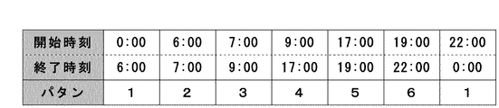
- FIG. 8A is a diagram showing an example of a first pattern switching table used in traffic signal control according to the present invention.
- FIG. 8B is a diagram showing another example of the first pattern switching table used in the traffic signal control according to the present invention.
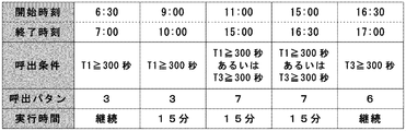
- FIG. 9 is a diagram showing an example of a second pattern switching table used in the traffic signal control according to the present invention.
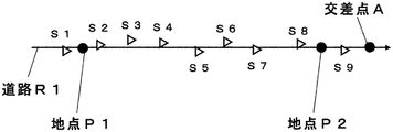
- FIG. 10 is a schematic diagram for explaining probe information created by the in-vehicle device 31.
- FIG. 11 is a diagram illustrating an example of the data content of probe information created by the in-vehicle device 31.
- FIG. 1 is a schematic diagram showing an outline of a traffic signal control system according to the present invention.
- the traffic signal control system includes a traffic signal device 1 (comprising a traffic signal controller 1a and a plurality of vehicle signal lamps 1b, 1c, etc.), a road communication device 21 such as an optical beacon (a communication antenna unit 21a and a communication control device 21b).
- the central device 4 is a device having a function of giving an instruction regarding control of the traffic signal 1, and a function of generating / transmitting traffic information to be provided to the vehicle, and is installed in the traffic control center.
- the central device 4 may be installed on the road instead of being installed in the traffic control center.
- the central device 4 is connected to traffic signals installed at each of a plurality of intersections via a communication line such as a telephone line and a communication device such as a router 5.
- the traffic signal 1 is connected to road communication devices 21 and 22 installed on each of a plurality of roads flowing into the intersection A between the road R1 and the road R2 via a communication line such as a telephone line.
- the traffic signal 1 has a function of controlling a plurality of signal lamps, and the right to pass a vehicle traveling on the road R1 toward the intersection A travels on the road R2 toward the intersection A by the vehicle signal lamp 1b.
- the right of traffic for the vehicle to be displayed is displayed by the vehicle signal lamp 1c.
- the traffic signal controller 1a has a function of receiving a signal control command, which is an instruction related to traffic information and control of the signal lamp, from the central device 4, and turns on / off each signal lamp such as the signal lamp 1b according to the instruction. And control blinking.
- a signal light device for pedestrians may be separately connected to the traffic signal controller 1a.
- FIG. 2 is a block diagram showing the configuration of the traffic signal controller 1a.
- the control unit 101 is composed of one or a plurality of microcomputers.
- the control unit 101 is connected to the lamp driving unit 102, the communication unit 103, and the storage unit 104 via an internal bus or the like, and the control unit 101 controls operations of these hardware units.
- the lamp drive unit 102 includes a semiconductor relay (not shown). Based on the signal lamp output command input from the control unit 101, each of the blue lamp, the yellow lamp, and the red lamp such as the plurality of signal lamps 1b and 1c is provided. The AC voltage (AC100V) or the DC voltage supplied to the signal lights of the respective colors is turned on / off in response to.
- the communication unit 103 includes a central communication unit 1031 for performing communication with the central device 4, and can receive traffic information, signal control commands, and the like from the central device 4. In addition, the communication unit 103 includes a terminal communication unit 1032 and transmits the received traffic information to the road communication device 21 or the like, or receives information on the in-vehicle device transmitted from the road communication device 21 or the like. Can be.
- the storage unit 104 stores received traffic information, information on signal control commands and in-vehicle devices, and information on various constants such as constants indicating the relationship between each floor and each display.
- the on-road communication devices 21 and 22 are provided on roads R1 and R2 that intersect each other, and are installed so as to be able to communicate with vehicles traveling on the outflow lane from the intersection A.
- this roadside communication device for example, an optical beacon, a radio beacon, a DSRC (Dedicated Short Range Communication), a WAVE (Wireless Access in Vehicle Environment), or a WiMAX (Worldwide intellite communication).
- a corresponding wireless communication device or the like is applicable, and it has a function of wirelessly communicating various types of information with the in-vehicle device.
- the installation point of this roadside communication apparatus 21 and 22 is not restricted to an outflow side lane.
- intersection A As long as information can be exchanged with a vehicle passing through the intersection A, it may be installed in any place.
- road-to-vehicle communication not only a road communication device installed in the vicinity of a road but also a road communication device capable of wide-area communication installed at a remote location may be used.
- FIG. 3 is a block diagram illustrating a configuration of the communication control device 21b of the road communication device 21.
- the communication control device 22b has the same configuration and function as the communication control device 21b.
- the control unit 201 is composed of one or a plurality of microcomputers, and controls the operation of each hardware unit such as the signal communication unit 203 connected via an internal bus or the like.
- road shape information related to a distance, a gradient, and the like from the road communication device 21 to the intersection A, information on an area including the intersection A, and the like are stored in advance. The information may be stored in advance or may be acquired from the central device 4 or the like and stored.
- the signal communication unit 203 has a function of receiving traffic information from the central device 4 via the traffic signal 1, and the road-to-vehicle communication unit 204 transmitting these information to the in-vehicle device via the communication antenna unit 21a. Further, information related to the in-vehicle device such as uplink information received by the road-to-vehicle communication unit 204 from the in-vehicle device is transmitted to the traffic signal controller 1a and the like by the signal communication unit 203.
- the central device 4 transmits traffic information and signal control commands to a plurality of traffic signals at a predetermined cycle.
- FIG. 4 is a diagram showing a format of a signal control command.
- split 1 indicates the split of current display 1
- split 6 indicates the split of current display 6.
- the details of this format are described in the standards issued by the New Traffic Management System Association (hereinafter referred to as UTMS Association).
- the road communication devices 21 and 22 do not have to be configured to communicate with the central device 4 via the traffic signal controller 1a. It is also possible to communicate with the device 4.
- a vehicle traveling on the road R ⁇ b> 1 (a vehicle traveling from left to right in FIG. 1) is equipped with an in-vehicle device 31 and wirelessly communicates various information with the on-road communication device 21.
- the vehicle equipped with the in-vehicle device 31 passes through the communication area Q1 of the road communication device 21 (the hatched portion on the road R1 in FIG. 1), the vehicle communicates wirelessly with the road communication device 21 and own vehicle Uplink information including information about ID is transmitted and traffic information is received.
- a vehicle traveling on the road R2 (a vehicle traveling from bottom to top in FIG. 1) is equipped with the in-vehicle device 32, and the communication area Q2 of the road communication device 22 (on the road R2 in FIG. 1).
- wireless communication is performed with the on-road communication device 22, and uplink information including information related to the own vehicle ID can be transmitted and traffic information can be received.
- the uplink information includes probe information indicating a travel locus of the vehicle (a broken line portion in FIG. 1) created by a method described later.
- Traffic signal control method The traffic signal control method according to the present invention will be described below.
- FIG. 7 is a parameter table storing pattern types that are combinations of a plurality of traffic signal control parameters.
- the first pattern switching table sets which pattern is selected in which time zone.
- the traffic signal control parameter of the specified pattern can be adopted.
- a method of performing traffic signal control according to time using this first pattern switching table is a conventional time control pattern selection method.
- the first pattern switching table of FIG. 8A only the time for switching the pattern is set. However, the start time and completion time of the time zone are set in the upper part of the table as shown in FIG. You may make it selectable. For example, as shown in FIG.
- the second pattern P1 (2) may be set to pattern 2.
- any data format may be used as long as the pattern can be selected according to the time.
- the time zone determined by the first pattern switching table and the corresponding pattern are defined as T1 (i) and B1 (i), respectively.
- i is an integer from 1 to m
- traffic signal control is performed using a second pattern switching table as shown in FIG. 9 in addition to the first pattern switching table. The details will be described below.
- FIG. 5 is a diagram showing a configuration of the central device 4 that determines traffic signal control parameters.
- the central device 4 is constituted by a computer device having a calculation function and a data storage function such as a workstation or a personal computer.
- the central control unit 401 corresponds to a CPU or the like of a computer device, and has a function of executing various data calculation processes and hardware control described below.
- the transmission / reception unit 403 has a function of exchanging information with the traffic signal controller 1a and the like via the router 5 and the like.
- the storage unit 402 stores various types of information such as the first pattern switching table and traffic information.
- the input information used for the calculation of the central control unit 401, the information related to the calculation result, and the information transmitted and received by the transmission / reception unit 403. Etc. are stored.
- the arithmetic processing for determining the traffic signal control parameters described below is executed using the central control unit 401 and the storage unit 402, and is usually realized as a computer program.
- the central control unit 401 refers to the current time acquired by the clock unit 404. Then, the pattern number corresponding to the current time is acquired from the first pattern switching table. For example, when the current time is 20:00, according to the first pattern switching table of FIGS. 8A and 8B, the time zone is included in “19:00 to 22:00” of B1 (6). Since pattern 1 is set as the pattern P1 (6) corresponding to this time zone, pattern 1 is selected.
- the second pattern switching table corresponding to the current time is referred to.
- This second pattern switching table is a table newly prepared in the present invention in order to improve the conventional time control pattern selection method using travel time. In the second pattern switching table of FIG.
- this second pattern switching table is not used for determining traffic signal control parameters.
- the time zone determined by the second pattern switching table and the corresponding pattern are defined as T2 (j) and B2 (j), respectively.
- j is an integer from 1 to n
- the traffic signal control parameter of pattern 1 set in the first pattern switching table is adopted.
- the cycle length is 60 seconds
- the split is 5: 5 (the same green time is allocated to the intersecting roads R1 and R2)
- the offset is 0 seconds (the green signal start time at the intersection serving as the offset reference and the intersection A
- a traffic signal control parameter of 0 seconds is adopted.
- the traffic signal control parameters are determined in the order of selecting a pattern once in the first pattern switching table and then referring to the second pattern switching table.
- the operation at the time when the calling condition or the like is actually set in the second pattern switching table of FIG. 9 will be described.
- the calling condition C2 (1) described here is a condition that T1 (travel time in the direction of traveling from the left to the right on the road R1) is 300 seconds or more.
- T3 is the travel time on the road traveling from the left to the right on the road R1.
- a method for calculating the travel time T1 will be described later.
- This calling condition is a conditional expression for determining whether or not the direction of traveling from the left to the right on the road R1 is congested. It is assumed that the travel time during non-congestion is usually about 240 seconds. That is, if the travel time is increased by 60 seconds (25%) or more than usual, it can be determined that the direction of traveling from the left to the right on the road R1 is congested.
- the calling condition C2 (1) is not satisfied, so the pattern 3 written in the second pattern switching table is not selected and the first pattern switching table is selected.
- the traffic signal control parameter of the pattern 2 acquired in the above is adopted to execute traffic signal control.
- the acquired travel time T1 is, for example, 350 seconds, this calling condition C2 (1) is satisfied, so that it is written in the second pattern switching table instead of the pattern 2 selected in the first pattern switching table.
- the traffic signal control is executed by adopting the traffic signal control parameter of the pattern 3 which is the pattern P2 (1). Since the execution time E2 (1) of the second pattern switching table is set to “continue”, the traffic signal control parameter of pattern 3 is adopted for 30 minutes until the end time 7:00. .
- this traffic signal control method is as follows. At this intersection A, as a result of analysis of traffic conditions by a skilled traffic signal control engineer, the traffic volume gradually increases from about 6:00, and after time 7:00, the road R1 is advanced from left to right. The conclusion was that the direction began to get crowded. Therefore, in the first pattern switching table, the pattern 2 to be selected after the time 6:00 has a cycle length (90 seconds) longer than the previous pattern 1 by 30 seconds. In addition, 60% of large blue hours are allocated to the road R1 side (40% of blue hours are on the intersecting road R2 side). Furthermore, when the time 7:00 has passed, the traffic volume further increases and congestion starts. Therefore, pattern 3 is selected to increase the traffic volume, and a longer cycle length (120 seconds) than pattern 2 is assigned. I did it.
- the traffic signal control by the pattern obtained in the first pattern switching table is performed when the traffic change time fluctuates.
- the traffic volume traveled at the intersection A before and after will be smaller than the capacity normally possessed (traffic volume travelable per unit time). For example, if the time when the road R1 actually starts to be crowded is earlier than the time 7:00 when the road R1 is expected to begin to be crowded, the traffic volume is such that the cycle length cannot be increased unless the cycle length is about 120 seconds.
- the cycle length remains at 90 seconds, the number of vehicles that can pass through the intersection A during one cycle is limited, and some of the vehicles waiting for the signal
- a single green signal cannot be passed.
- Such vehicles are forced to wait for the signal until the next cycle in which a green light is displayed again in the direction of the road R1, so that the remaining vehicles are accumulated and the signal waiting queue in the direction of the road R1 is rapidly increasing in several cycles. It will grow and traffic jams will occur.
- a second pattern switching table is prepared in addition to the first pattern switching table, and in this second pattern switching table, time 6:30 to time 7: 30 minutes earlier than time 7:00.
- the traffic signal control parameter of pattern 3 that was scheduled to be adopted after 7:00 at an earlier stage than usual according to the travel time can be adopted until 00. It has become possible to control flexibly even if it changes faster than usual. That is, by using this second pattern switching table, it was scheduled to be adopted in the time zone B1 (k) in the time zone from slightly before the end time of a certain time zone B1 (k) to the end time.
- the next time zone is the time zone B1 (1) where the date has changed, and thus P1 (k + 1) P1 (1) corresponding to the time zone B1 (1) may be adopted ahead of schedule.
- a method of adopting the pattern set in the first pattern switching table ahead of schedule is adopted in case the traffic situation changes earlier than expected, such as around 6:00 to 7:00.
- the second time zone in the second pattern switching table the time zone where the start time is 9:00 and the end time is 10:00
- the operation for when the traffic situation changes later than expected is performed.
- the time from 7:00 to 9:00 (time zone B1 (3)) is pattern 3, but the time after 9:00 (time zone B1 (4)) ) To switch to pattern 4. It is assumed that after 9:00, the traffic situation that started to be crowded from around 7:00 will be settled down and the traffic volume will be reduced, and it will settle down to a degree that can make even a cycle length (90 seconds) shorter than Pattern 3. Because it is.
- the traffic signal control parameter of pattern 3 should be used continuously, but only the first pattern switching table.
- the cycle length is shortened to 90 seconds, so that the congested traffic situation may become more serious.
- the second pattern switching table of the present invention is used, the travel time T1 is still 300 seconds in the time zone B2 (2) (the time zone where the start time is 9:00 and the end time is 10:00). If the situation exceeds (for example, 330 seconds), the traffic signal control parameter (cycle length 120 seconds) of pattern 3 (P2 (2)) can be continuously extended and employed.
- the execution time E2 (2) is set to 15 minutes. If T1 is 300 seconds or more at 00 and it is determined that pattern 3 will be used continuously, pattern 3 will be used at least until time 9:15. This is to prevent the pattern from changing rapidly in a short time. If T1 is less than 300 seconds after time 9:15, the traffic signal control parameter (cycle length 120 seconds) of pattern 4 set in the first pattern switching table is adopted. .
- the end time of a certain time zone B1 (k-1) (the start time of the time zone B1 (k)) is earlier than the end time of the time zone B1 (k).
- P1 (k) that was originally planned to be adopted from the start time of the time zone B1 (k)
- the previous time zone is the time zone B1 (m) before the date changes, and thus the P1 (k ⁇ 1) ) May be adopted by extending P1 (m) corresponding to the time zone B1 (m) which is the previous time zone.
- the traffic signal control parameters can be moved forward than usual. It can be adopted or extended.
- zone B2 (3) (The start time country and end time of the switching time B1 (4) (time 9:00 and 17:00) of the first pattern switching table, such as the start time is 11:00 and the end time is 15:00. May be set independently.
- this time zone B2 (3) (time zone where the start time is 11:00 and the end time is 15:00)
- the traffic volume temporarily increases in the daytime time zone, and the road R1 If the two-way travel time T1 and T3 is 300 seconds or more, pattern 7 (P2 (3)) is adopted so that the cycle length can be increased by 30 seconds to 120 seconds. is there.
- a license plate reader is installed at each of the start and end points of the road section where travel time is to be acquired.
- a method in which the difference in time when the same license plate is read is used as travel time.
- a road communication device that performs narrow area communication such as an optical beacon is set at each of the start point and end point of a road section for which travel time is to be acquired, and the two vehicles have the same vehicle ID at the two points.
- the above method can be used, but the travel time is calculated using probe information collected from a vehicle equipped with the in-vehicle devices 31 and 32 having a function of uplinking probe information. Is preferred.
- the in-vehicle devices 31 and 32 will be described in detail with reference to FIG.
- the in-vehicle control unit 301 is composed of one or a plurality of microcomputers.
- the in-vehicle control unit 301 controls the operation of each hardware unit such as the in-vehicle communication control unit 303 connected via an internal bus or the like.
- the storage unit 302 stores a vehicle ID in advance, and the in-vehicle control unit 301 creates uplink information including the vehicle ID. Then, the in-vehicle communication control unit 303 transmits the created uplink information to the road communication device 21.
- the GPS receiving unit 305 can grasp the current position and the current time of the vehicle, and the in-vehicle control unit 301 discretizes sample points in which the position where the vehicle has passed and the passage time are associated with each other. It has a function to create recorded probe information.
- the timing for recording the sample points may be, for example, a method of recording at a constant cycle (every 10 seconds or every 100 meters), or when the vehicle running state changes such as turning left / right or starting / stopping. It is also possible to use a method such as recording.
- the sensor since various sensors may be attached to the vehicle, information on such sensors may be included in the probe information after being acquired by the sensor information receiving unit 304.
- the sensor include a millimeter wave radar that measures the distance between vehicles ahead and behind, a sensor that detects the number of passengers in the vehicle, and a sensor that acquires weather conditions such as temperature and humidity.
- the uplink information including the probe information and the vehicle ID generated in this way is transmitted to the road communication device 21 and the like via the vehicle-mounted antenna connected to the vehicle-mounted communication control unit 303. As shown in FIG. 1, if roadside communication devices 21 and 22 are installed in the vicinity of intersection A, probe information can be collected from a plurality of vehicles passing through intersection A.
- the probe information received by the central device 4 via the roadside communication device 21 or the like is as shown in the schematic diagram of FIG. 10, and the content of the data is as shown in FIG. Describes the contents of the processing for calculating the travel time (latitude / longitude data is omitted in FIG. 11).
- sample points S1 to S9 recorded by the in-vehicle device 31 are schematically shown.
- the reason why the sample point is also recorded outside the road R1 is that the latitude / longitude information acquired by the GPS receiver 305 has an error of about several tens of meters at the maximum.
- T1 the travel time between points P1 and P2 upstream from the intersection A of the road R1 (left side of the intersection A in FIG. 1) is calculated as T1.
- the point P1 is based on this probe information.
- P2 are estimated, and the difference between the passage times is calculated as travel time T1.
- the central control unit 401 can acquire the travel time T1 from one piece of probe information, but can acquire the travel time T1 from a plurality of probe information acquired in unit time (for example, 5 minutes). You can also. For example, if 10 pieces of probe information can be acquired per unit time, the average value may be the travel time T1 at that time, or a vehicle that has traveled extremely differently from many other vehicles (for example, In order to exclude data such as vehicles that took a long time because of stopping for a predetermined time between the points P1 and P2, the average value is calculated by excluding the maximum value and the minimum value, and the value is calculated as the travel time T1. It is also good.
- T3 can be calculated using probe information obtained from a vehicle traveling from right to left on the road R1.
- the probe information used for calculating the travel time may be limited to probe information obtained from public vehicles that periodically travel around the road R1.
- the vehicle ID assigned to the public vehicle is a number different from the vehicle ID assigned to the general vehicle, and it is possible to distinguish whether the vehicle is a public vehicle by the vehicle ID. Therefore, the central control unit 401 first determines from the vehicle ID included in the obtained uplink information whether the vehicle that has transmitted the uplink information is a public vehicle. If the vehicle is not a public vehicle, the probe information is not used for calculating the travel time T1 or the like. If the vehicle is a public vehicle, the probe information is used for calculating the travel time T1 or the like. Then, based on only the probe information obtained from the public vehicle, the travel time T1 and the like are calculated by the same method as described above.
- the advantage of limiting the probe information to that of public vehicles is as follows.
- the probe information obtained from a general vehicle varies in the number and accuracy of data obtained according to the mounting rate of the in-vehicle device capable of creating the probe information. Especially in regions where the mounting rate is low, there may be a large difference in the accuracy of travel time obtained between a time zone where the number of probe information obtained is small and a time zone where there is a lot of probe information.
- the probe information is limited to that of public vehicles, it can be expected that a professional driver who repeatedly drives the same route will perform stable driving without sudden acceleration or deceleration, etc. There is a high possibility that correctly reflected probe information is obtained, and even when the absolute number of obtained probe information is small, more accurate calculation of travel time can be expected.
- an in-vehicle device that can create probe information is installed on all public vehicles, the advantage is that probe information can be obtained reliably for the number of public vehicles scheduled to pass per unit time.
- the execution time for example, 15 minutes
- the period for example, 10 minutes
- the next determination of the calling condition C2 Since the travel time that is newer than the time of the previous judgment is always obtained at the time of execution (after the execution time has elapsed), it is possible to always select a pattern based on the new travel time. Is advantageous.
- the communication between the traffic signal controller 1a and the roadside communication devices 21 and 22 may be wireless communication or wired communication, and one or a plurality of information relay devices that relay the exchange of information.
- the structure provided between these apparatuses may be used.
- the traffic signal controller 1a and the road communication device 21 and the like are configured to be housed in separate housings, but the present invention is not limited thereto, and traffic signal control is performed.
- the configuration in which the machine 1a, the road communication device 21 and the like are housed in one housing may be employed.
- the exchange of information between the traffic signal controller 1a and the on-road communication device 21 or the like may be performed using any of wired, wireless, and internal buses.
- the central control unit 401 of the central device 4 determines the traffic signal control method, but it may be determined by the traffic signal controller 1a. That is, the traffic signal controller 1a holds the first and second pattern switching tables, and the traffic signal controller 1a receives the uplink information via the road communication devices 21 and 22, and is calculated from the uplink information. It may be possible to determine which pattern is selected using the travel time T1 or the like. Further, these processes may be executed in other road devices (for example, the information relay device).
- This traffic signal control system makes use of the advantages of both the time control pattern selection method and the travel time pattern selection method, and there are errors and uncertainties in the traffic information such as travel time obtained.
- the present invention can be suitably used for traffic signal control adapted to a traffic situation in which an assumed traffic demand is likely to fluctuate.
Landscapes
- Physics & Mathematics (AREA)
- General Physics & Mathematics (AREA)
- Traffic Control Systems (AREA)
Abstract
Description
これらのパタン選択式の交通信号制御方法は、交通量や渋滞長に応じて逐次信号制御パラメータを算出する方式に比べて簡易に導入することができると共に、記憶してある複数のパタンのいずれかでしか動作しないため、逐次算出する場合に比べて、想定外の制御方法となる心配がない、という利点がある。
また、時間制御のパタン選択方式の場合、事前に想定する交通需要にほとんど変動が生じない地域における交通信号制御であれば、何ら問題はないが、混雑し始める時刻や混雑が解消し始める時刻等にばらつきがある地域では、その時間帯に選択されるパタンが実際の交通状況にそぐわないケースがあり、時刻のみに基づいてパタンを選択する方式にも改善の余地がある。
なお、ここでiは1乃至mの整数であり、mは前記第一パタン切替テーブルで規定される時間帯の数である。
このようにすることで、特定の時間帯においては、旅行時間情報に基づいてより適切と思われる交通信号制御パラメータを選択できるようになるため、単なる時間制御のパタン選択方式よりも交通状況に順応した交通信号制御を行うことが可能になる。
また、このシステムでは、時刻に応じてパタンを選択することを基本としているので、旅行時間のみに応じて信号制御パラメータを選択する方式に比べると、大半の時間帯においては事前に熟練した交通管理者が設定した交通信号制御パラメータを選択することができるため、もし仮に車両感知器等で取得される旅行時間情報が実際の交通状況と乖離しているような場合であっても、ほとんどの時間帯で適切な動作をすることが可能となり、システムのロバスト性が高くなる。
なお、ここでkは1乃至mの整数のうちのいずれかであり、k=mの場合には、前記(k+1)を(1)とする。
なお、ここでkは1乃至mの整数のうちのいずれかであり、k=1の場合には、前記(k-1)を(m)とする。
旅行時間取得手段で取得される旅行時間は、例えば1台の車両が何らかの事情で道路上で立ち往生等した影響で一時的に大きく変動するケースがあるが、その原因となる1台が移動した後には、間もなく平常な状態に戻ることも少なくない。
そこで、第二時間帯T2においては、例えば10分や15分といった周期で旅行時間に基づく指標を複数回算出し、一時的には変動したが、すぐに第一パタン切替テーブルを設定した時に事前予想していた交通状況に戻ったような場合には、第一パタン切替テーブルに設定した交通信号制御パラメータに戻すことができるようにした。
このように、第一パタン切替テーブルと第二パタン切替テーブルとを柔軟に行き来できるようにすることで、より一層交通状況に適した交通信号制御を行うことが可能になる。
旅行時間を取得する場合に、プロの運転手が同じ経路を繰り返し巡回するバス等の公共車両から得られるプローブ情報を使用する方が、不特定の車両からのプローブ情報を使用する場合に比べて、運転手の性質や車載機の搭載率等の影響を受け難いため、時間帯毎の交通状況の変動を正確に把握しやすい。
そこで、旅行時間をこのような公共車両のプローブ情報から得ることを前提とした上で、第二時間帯における前記所定時間を公共車両からプローブ情報を取得できる間隔よりも長くしておけば、交通信号制御パラメータ選択時に新しいプローブ情報から得られる旅行時間情報に基づく指標を用いることができ好適である。
〔システムの全体構成〕
以下、本発明の実施の形態を、添付図面を参照しながら詳細に説明する。図1は、本発明に係る交通信号制御システムの概要を示す模式図である。なお、本発明の図面において、同一の参照符号は、同一部分または相当部分を表わすものとする。
交通信号制御システムは、交通信号機1(交通信号制御機1aと複数の車両用信号灯器1b、1c等で構成)、光ビーコン等の路上通信装置21(通信アンテナ部21aと通信制御装置21bで構成)及び路上通信装置22(通信アンテナ部22aと通信制御装置22bで構成)、道路R1や道路R2を走行する車両に搭載された車載装置31と32、中央装置4、ルータ5等を含む。中央装置4は、交通信号機1の制御に関する指示を行う機能や、車両に対して提供する交通情報の生成・送信等を行う機能を備えた装置であり、交通管制センター内に設置されている。なお、中央装置4は、交通管制センター内に設置されず、道路上に設置されていても良い。
中央装置4は、複数の交差点のそれぞれに設置された交通信号機と電話回線などの通信回線やルータ5等の通信装置を介して接続されている。交通信号機1は、道路R1と道路R2の交差点Aに流入する複数の道路のそれぞれに設置された路上通信装置21および22と電話回線などの通信回線を介して接続されている。
交通信号制御機1aは、中央装置4から交通情報や信号灯器の制御に関する指示である信号制御指令を受信する機能を備えており、指示に応じて信号灯器1b等の各信号灯器の点灯、消灯及び点滅を制御する。
なお、交差点Aに横断歩道がある場合には、交通信号制御機1aに別途歩行者用の信号灯器が接続されることもある。
通信部103は、中央装置4との間の通信を行うための中央通信部1031を備えており、中央装置4から交通情報や信号制御指令等を受信することができる。また、通信部103は、端末通信部1032を備えており、受信した前記交通情報を路上通信装置21等へ送信したり、路上通信装置21等から送られてくる車載装置に関する情報等を受信したりすることができる。
記憶部104は、受信した交通情報、信号制御指令や車載装置に関する情報、各階梯と各現示との関係を表す定数などの各種定数の情報などを記憶している。
なお、この路上通信装置21や22の設置地点は、流出側車線に限らない。交差点Aを通過する車両との間で情報をやり取りできるのであればどのような場所に設置されていても良い。また、路車間通信においては、道路付近に設置した路上通信装置だけではなく、離隔した地点に設置された広域通信が可能な路上通信装置を用いても良い。
制御部201は、1又は複数のマイクロコンピュータから構成されており、内部バス等を介して接続された信号通信部203等のハードウェア各部の動作を制御する。
記憶部202には、当該路上通信装置21から交差点Aまでの距離や勾配等に関する道路形状情報や交差点Aを含む地域の情報等が予め記憶されている。なお、これらの情報は、予め記憶している構成でも中央装置4等から取得して記憶する構成でも良い。
また、路車間通信部204が車載装置から受信したアップリンク情報等の車載装置に関する情報は、信号通信部203によって交通信号制御機1a等に対して送信される。
なお、路上通信装置21や22は、交通信号制御機1aを経由して中央装置4と通信する構成でなくても良く、ルータ5や通信回線等により交通信号制御機1aを経由せずに中央装置4と通信することもできる。
道路R2上を走行する車両(図1で下から上に向かって走行する車両)についても同様に車載装置32を搭載しており、路上通信装置22の通信領域Q2(図1の道路R2上の斜線部分)を通過する際に、路上通信装置22との間で無線通信を行い、自己の車両IDに関する情報を含むアップリンク情報を送信すると共に交通情報を受信することができるようになっている。
なお、このアップリンク情報には、後述する方法で作成される車両の走行軌跡(図1の破線部分)を示すプローブ情報が含まれている。
以下に、本発明にかかる交通信号制御方法について説明する。
なお、図8Aの第一パタン切替テーブルでは、パタンを切り替える時刻のみが設定されているが、テーブルの上段に図8Bのように時間帯の開始時刻と修了時刻を設定してそれに応じたパタンを選択できるようにしても構わない。例えば、図8Bのように1つ目の時間帯B1(1)である「0:00~6:00」では、1つ目のパタンP1(1)としてパタン1を設定し、2つ目の時間帯B1(2)である「6:00~7:00」では、2つ目のパタンP1(2)としてパタン2と設定しても構わない。すなわち、時刻に対応してパタンを選択できるような形式であれば、どのようなデータ形式であっても良い。
ここで、この第一パタン切替テーブルによって決まる時間帯とそれに対応するパタンをそれぞれ、T1(i)とB1(i)と定義することにする。ここで、iは1乃至mの整数であり、mは第一パタン切替テーブルで規定された時間帯の数を表す。なお、図8の例であればm=7である。
以下にその内容を詳述する。
通常、中央装置4は、ワークステーションやパーソナルコンピュータのような演算機能とデータ記憶機能を備えたコンピュータ装置で構成される。
中央制御部401は、コンピュータ装置のCPU等に該当し、以降で説明する各種データの演算処理やハードウェアの制御等を実行する機能を備えている。
送受信部403は、ルータ5等を介して交通信号制御機1a等と情報のやりとりを行う機能を備えている。
記憶部402は、前記第一パタン切替テーブルや交通情報等の様々な情報を記憶しており、中央制御部401の演算に用いられる入力情報や演算の結果に関する情報、送受信部403が送受信する情報等を記憶する機能を備えている。
以下で説明する交通信号制御パラメータを決定するための演算処理は、この中央制御部401と記憶部402を用いて実行されるものであり、通常はコンピュータプログラムとして実現されるものである。
そして、前記第一パタン切替テーブルから、その現在時刻に対応するパタンの番号を取得する。
例えば、現在時刻が20:00の場合、図8Aや図8Bの第一パタン切替テーブルによれば、時間帯としては、B1(6)の「19:00~22:00」に含まれており、この時間帯に対応するパタンP1(6)としては、パタン1が設定されているため、パタン1を選択する。
次に、この現在時刻に対応する第二パタン切替テーブルを参照する。この第二パタン切替テーブルは、従来までの時間制御のパタン選択方式を旅行時間を用いて高度化するために本発明において新たに用意したテーブルである。
図9の第二パタン切替テーブルでは、5つの時間帯B2(1)乃至B2(5)に対応した呼出条件C2(1)乃至C2(5)や実行時間E2(1)乃至E2(5)等が設定されているが、20:00が該当する時間帯が存在しないため、この第二パタン切替テーブルについては、交通信号制御パラメータの決定には用いられない。
なお、第二パタン切替テーブルでも第一パタン切替テーブルと同様に、この第二パタン切替テーブルによって決まる時間帯とそれに対応するパタンとをそれぞれ、T2(j)とB2(j)と定義することにする。ここで、jは1乃至nの整数であり、nは第二パタン切替テーブルで規定された時間帯の数を表す。なお、図9の例であればn=5である。
以降では、図9の第二パタン切替テーブルで実際に呼出条件等が設定された時刻の動作について説明する。
その後、時刻6:30になる時点までは、そのままパタン2で動作をし続けるが、時刻6:30になった時点で、図9の第二パタン切替テーブルの一番左端の時間帯B2(1)に該当したので、この第二パタン切替テーブルの時間帯B2(1)に記載された呼出条件C2(1)についての判定が行われる。
この呼出条件は、道路R1を左から右に進む方向が混雑しているのかどうか、を判断するための条件式であり、通常、非渋滞時の旅行時間が240秒程度であるものとする。つまり、通常時よりも旅行時間が60秒(25%)以上も増大しているのであれば、道路R1を左から右に進む方向が混雑していると判断できる、ということになる。
一方、取得された旅行時間T1が例えば350秒であれば、この呼出条件C2(1)を満足するので、第一パタン切替テーブルで選択されたパタン2ではなく、第二パタン切替テーブルに書かれたパタンP2(1)であるパタン3の交通信号制御パラメータを採用して交通信号制御を実行する。
なお、第二パタン切替テーブルの実行時間E2(1)には、「継続」と設定されているので、終了時刻の7:00までの30分間は、パタン3の交通信号制御パラメータが採用される。
この交差点Aでは、熟練の交通信号制御技術者が交通状況を分析した結果、時刻6:00頃から徐々に交通量が増えていき、時刻7:00を過ぎると道路R1を左から右に進む方向が混雑し始めるとの結論を得ていたのである。
従って、第一パタン切替テーブルでは、時刻6:00を過ぎた時点で選択するパタン2には、それ以前のパタン1に比べて30秒長いサイクル長(90秒)を設定しており、スプリットに関しても道路R1側に6割の大きな青時間(交差する道路R2側には4割の青時間)を割り当てるようにしているのである。
さらに、時刻7:00を過ぎた時点では、さらに交通量が増えて混雑し始めるので、その交通量を捌くためにパタン3を選択し、パタン2よりもさらに長いサイクル長(120秒)を割り当てるようにしたのである。
例えば、道路R1が混雑し始めると予想された時刻7:00よりも実際に混雑し始める時刻が早かった場合、本来はサイクル長を120秒程度の長さにしなければ捌ききれない程度の交通量になっているにも関わらず、サイクル長を90秒のままにしているために、1サイクルの間に交差点Aを通過できる車両の台数が限定され、信号待ちしていた車両のうちの一部が1回の青信号だけでは、通過しきれない可能性が高くなる。このような車両は、再び道路R1方向に青信号が表示される次のサイクルまで信号待ちを強いられるため、捌け残り車両が累積して、道路R1方向の信号待ち車列が数サイクルの間にどんどん延びていき、渋滞が発生することになってしまう。
つまり、本発明のように、第一パタン切替テーブルに加えて第二パタン切替テーブルを用意し、この第二パタン切替テーブルにおいて、時刻7:00よりも30分早い時刻6:30から時刻7:00までの間に、旅行時間に応じて通常よりも早い段階で時刻7:00以降に採用される予定だったパタン3の交通信号制御パラメータを採用することができるようにしたので、交通状況がいつもより早く変化した場合にも柔軟に制御することが可能になった。
すなわち、この第二パタン切替テーブルを用いることにより、ある時間帯B1(k)の終了時刻よりも少し前から終了時刻までの間の時間帯において、当該時間帯B1(k)で採用予定だったパタンP1(k)に代えてその次の時間帯B1(k+1)で採用予定だったP1(k+1)を前倒しで採用できるようになった(k=1乃至m)。
なお、時間帯B1(m)の終了時刻付近で同様の処理を行う場合には、その次の時間帯は、日付が変わった時間帯B1(1)となるので、前記P1(k+1)としては、時間帯B1(1)に対応するP1(1)を前倒しで採用すれば良い。
第一パタン切替テーブルによれば、時刻7:00から時刻9:00までの間(時間帯B1(3))は、パタン3だが、時刻9:00を過ぎた時点(時間帯B1(4))でパタン4に切り替えるように設定されている。
これは、時刻9:00を過ぎたら時刻7:00頃から混雑し始めた交通状況が一段落して交通量が減り、パタン3よりも短いサイクル長(90秒)でも捌ける程度に落ち着く、と想定されているからである。
しかしながら、本発明の第二パタン切替テーブルを使用すれば、前記時間帯B2(2)(開始時刻が9:00で終了時刻が10:00の時間帯)においても依然として旅行時間T1が300秒を超えるような状況(例えば330秒)であれば、引き続きパタン3(P2(2))の交通信号制御パラメータ(サイクル長120秒)を延長して採用することができるようになる。
そして、時刻9:15を過ぎた時点でT1が300秒未満となっていれば、第一パタン切替テーブルで設定されたパタン4の交通信号制御パラメータ(サイクル長120秒)を採用することになる。
なお、時間帯B1(1)の開始時刻付近で同様の処理を行う場合には、その前の時間帯は、日付が変わる前の時間帯B1(m)となるので、前記P1(k-1)としては、1つ前の時間帯である時間帯B1(m)に対応するP1(m)を延長して採用するようにすれば良い。
このように、交通状況の変動が想定よりも早かったり遅かったりしたとしても、第一パタン切替テーブルに加えて第二パタン切替テーブルを使用することで、交通信号制御パラメータを通常よりも前倒しして採用したり延長して採用したりすることが可能になる。
この時間帯B2(3)(開始時刻が11:00で終了時刻が15:00の時間帯)は、昼間の時間帯において一時的に交通量が増えて混雑するケースを想定して、道路R1の双方向の旅行時間T1及びT3が300秒以上になった場合には、パタン7(P2(3))を採用してサイクル長を30秒長い120秒にすることができるようにしているのである。
以下では、本発明を実施するに当たって必要な入力条件である旅行時間T1等の取得方法について説明する。
車載制御部301は、1又は複数のマイクロコンピュータから構成されている。車載制御部301は、内部バス等を介して接続された車載通信制御部303等のハードウェア各部の動作を制御する。
記憶部302には、車両IDが予め記憶されており、車載制御部301は、この車両IDを含むアップリンク情報を作成する。そして、車載通信制御部303は、作成された当該アップリンク情報を路上通信装置21に送信する。
このサンプル点を記録するタイミングとしては、例えば一定の周期で(10秒毎や100メートル走行する毎に)記録するという方法でも良いし、右左折や発進・停止といった車両の走行状態が変動した場合に記録するといった方法でも良い。
このようにして作成されたプローブ情報や前記車両ID等を含むアップリンク情報は、車載通信制御部303に接続された車載アンテナを介して路上通信装置21等に対して送信される。
図1にあるように、交差点Aの近傍に路上通信装置21や22を設置しておけば、交差点Aを通過する複数の車両からプローブ情報を収集することが可能になる。
図10では、車載装置31が記録したサンプル点S1~S9を模式的に示している。サンプル点が道路R1を外れたところにも記録されているのは、GPS受信部305によって取得される緯度・経度の情報に最大で数十メートル程度の誤差があるためである。
ここでは、道路R1の交差点Aよりも上流側(図1における交差点Aの左側)の地点P1とP2の間の旅行時間をT1として算定するものとする。車載装置31が交差点Aを通過後に路上通信装置21に対して送信するアップリンク情報に含まれるプローブ情報が図10や図11のようなものであった場合、このプローブ情報に基づいて、地点P1とP2の通過時刻を推定した上で、その通過時刻の差を旅行時間T1として算定する。
同じように地点P2については、S8の通過時刻が10:29:04でS2の通過時刻が10:29:44であるので、その間の地点P2の通過時刻は、これら2つの時刻の中央の時刻である10:29:24と推定することができる。
以上から、この地点P1とP2の間の通過時刻の差は、4分33秒と算出され、273秒が旅行時間T1として算出される。
プローブ情報に基づいて旅行時間T1を算出する場合、旅行時間の算出に用いるプローブ情報を、この道路R1を定期的に巡回する公共車両から得られるプローブ情報に限定するようにしても良い。
公共車両に付与される車両IDは、一般車両に付与される車両IDとは異なる番号であり、車両IDによって公共車両か否かを区別することが可能である。
したがって、中央制御部401は、まず、得られたアップリンク情報に含まれる車両IDから、そのアップリンク情報の送信元の車両が公共車両であるかどうかを判別する。そして、もし公共車両以外であればそのプローブ情報は、旅行時間T1等の算出には用いず、公共車両であればそのプローブ情報を旅行時間T1等の算出に用いることにする。
そして、公共車両から得られたプローブ情報のみに基づいて、前述と同様の方法で旅行時間T1等を算出する。
一般車両から得られるプローブ情報は、プローブ情報を作成することが可能な車載装置の搭載率に応じて、得られるデータの数や精度にバラツキが生じる。特に搭載率が低い地域においては、得られるプローブ情報の数が少ない時間帯と多い時間帯とで、得られる旅行時間の精度に大きな差が生じる可能性がある。
また、一般車両の場合には、例えば途中の店舗で寄り道したり、路側に停止して地図を確認したりするといった通常とは異なる走行をする車両もあるし、ドライバの運転時の癖等によって得られる旅行時間に一定以上のバラツキが生じると予想される。従って、そういった車両から得られる旅行時間は、実際の交通流とは異なることもありうる。
そして、判定を行う周期である実行時間(例えば15分)をこの旅行時間を算出する周期(例えば10分)よりも長くしておけば、一旦パタンを選択してから次に呼出条件C2の判定を行う時点(実行時間経過後の時点)においては、前回の判定時よりも新しい旅行時間が必ず得られていることになるため、常に新しい旅行時間に基づいてパタンを選択することが可能となり非常に有利である。
すなわち、交通信号制御機1aで第一および第二のパタン切替テーブルを保持すると共に、路上通信装置21や22経由で交通信号制御機1aがアップリンク情報を受信し、当該アップリンク情報から算出される旅行時間T1等を用いて、どのパタンを選択するかを決定するようにしても良い。また、その他の路上装置(例えば前記情報中継装置等)においてこれらの処理を実行するようにしても良い。
1b、1c 信号灯器
101 制御部、 102 灯器駆動部、 103 通信部、 1031 中央通信部、 1032 端末通信部、 104 記憶部、
21、22 路上通信装置
21a、22a 通信アンテナ部、 21b、22b 通信制御装置
201 制御部、 202 記憶部、 203 信号通信部、 204 路車間通信部
31、32 車載装置
301 車載制御部、 302 記憶部、 303 車載通信制御部、 304 センサー情報受信部、 305 GPS受信部
4 中央装置、 5 ルータ
A 交差点、 Q1、Q2 通信領域、 R1、R2 道路、 P1、P2 地点、 S1乃至S9 プローブ情報のサンプル点
Claims (7)
- 1日の全時間帯を複数の第一時間帯に分割した第一タイムスケジュールの各第一時間帯B1(i)に対応付けて交通信号制御パラメータP1(i)を設定した第一パタン切替テーブルを記憶する記憶手段と(ここで、iは1乃至mの整数であり、mは前記第一パタン切替テーブルで規定される時間帯の数である。)、
記憶された当該第一パタン切替テーブルから現在時刻に対応する交通信号制御パラメータを選択する選択手段と、
当該選択された交通信号制御パラメータを用いて交通信号灯器を制御する制御手段と、
前記交通信号灯器近傍の1又は複数の道路区間における車両の旅行時間情報を取得する旅行時間取得手段とを備える交通信号制御システムにおいて、
前記記憶手段には、1日の全時間帯のうちの一部のみで構成された第二時間帯T2における旅行時間に関する第二条件と当該第二条件に合致した場合に選択される交通信号制御パラメータP2とを対応付けて設定した第二パタン切替テーブルがさらに記憶されると共に、
前記旅行時間取得手段で取得される旅行時間情報に基づいて得られる指標が前記第二条件に合致するか否かを判定する判定手段をさらに備え、
その判定手段が前記第二条件に合致すると判定した場合に、前記選択手段が、交通信号制御パラメータP1(i)に代えて、第二パタン切替テーブルに設定された交通信号制御パラメータP2を選択するように構成されていること
を特徴とする交通信号制御システム。 - 前記第二時間帯T2の終了時刻を前記第一タイムスケジュールに含まれる第一時間帯のうちの一の第一時間帯B1(k)の終了時刻にすると共に(ここで、kは1乃至m)の整数のうちのいずれかである)、前記第二時間帯の開始時刻を前記一の第一時間帯B1(k)の開始時刻よりも後の時刻に設定した上で、第二パタン切替テーブルにおいてこの第二時間帯T2に対応付けて設定される交通信号制御パラメータP2を、前記一の第一時間帯B1(k)に続く後続の第一時間帯B1(k+1)に対応付けて第一パタン切替テーブルに設定された交通信号制御パラメータP1(k+1)とすること(ただし、k=mの場合には、前記(k+1)を(1)とする)
を特徴とする請求項1に記載の交通信号制御システム。 - 前記第二時間帯T2の開始時刻を前記第一タイムスケジュールに含まれる第一時間帯のうちの一の第一時間帯B1(k)の開始時刻にすると共に(ここで、kは1乃至mの整数のうちのいずれかである)、前記第二時間帯の終了時刻を前記一の第一時間帯B1(k)の終了時刻よりも前の時刻に設定した上で、第二パタン切替テーブルにおいてこの第二時間帯T2に対応付けて設定される交通信号制御パラメータP2を、前記一の第一時間帯B1(k)よりも1つ前の第一時間帯B1(k-1)に対応付けて第一パタン切替テーブルに設定された交通信号制御パラメータP1(k-1)とすること(ただし、k=1の場合には、前記(k-1)を(m)とする)
を特徴とする請求項1に記載の交通信号制御システム。 - 前記判定手段による判定を第二時間帯T2において所定時間毎に行うようにした上で、判定の結果第二条件に合致しなくなった場合には、前記選択手段は、当該判定実行時刻に対応して第一パタン切替テーブルに設定された交通信号制御パラメータを選択する
請求項1乃至3のいずれか1つに記載の交通信号制御システム。 - 前記旅行時間取得手段による旅行時間の取得は、前記交通信号灯器設置地点を路線上に含む複数の公共車両に搭載される車載機から送信される走行軌跡情報であるプローブ情報に基づいて行うように構成されており、
前記所定時間が、前記複数の公共車両が前記交通信号灯器設置地点を通過する時間間隔よりも長く設定されている
請求項1乃至4のいずれか1つに記載の交通信号制御システム。 - 1日の全時間帯を複数の第一時間帯に分割した第一タイムスケジュールの各第一時間帯B1(i)に対応付けて交通信号制御パラメータP1(i)を設定した第一パタン切替テーブルを記憶する記憶手段と(ここで、iは1乃至mの整数であり、mは前記第一パタン切替テーブルで規定される時間帯の数である。)、
記憶された当該第一パタン切替テーブルから現在時刻に対応する交通信号制御パラメータを選択する選択手段と、
当該選択された交通信号制御パラメータを用いて交通信号灯器を制御する制御手段と、
前記交通信号灯器近傍の1又は複数の道路区間における車両の旅行時間情報を取得する旅行時間取得手段とを備える交通信号制御装置において、
前記記憶手段には、1日の全時間帯のうちの一部のみで構成された第二時間帯T2における旅行時間に関する第二条件と当該第二条件に合致した場合に選択される交通信号制御パラメータP2とを対応付けて設定した第二パタン切替テーブルがさらに記憶されると共に、
前記旅行時間取得手段で取得される旅行時間情報に基づいて得られる指標が前記第二条件に合致するか否かを判定する判定手段をさらに備え、
その判定手段が前記第二条件に合致すると判定した場合に、前記選択手段が、交通信号制御パラメータP1(i)に代えて、第二パタン切替テーブルに設定された交通信号制御パラメータP2を選択するように構成されていること
を特徴とする交通信号制御装置。 - 1日の全時間帯を複数の第一時間帯に分割した第一タイムスケジュールの各第一時間帯B1(i)に対応付けて交通信号制御パラメータP1(i)を設定した第一パタン切替テーブルを記憶する記憶ステップと(ここで、iは1乃至mの整数であり、mは前記第一パタン切替テーブルで規定される時間帯の数である。)、
記憶された当該第一パタン切替テーブルから現在時刻に対応する交通信号制御パラメータを選択する選択ステップと、
当該選択された交通信号制御パラメータを用いて交通信号灯器を制御する制御ステップと、
前記交通信号灯器近傍の1又は複数の道路区間における車両の旅行時間情報を取得する旅行時間取得ステップとを備える交通信号制御方法において、
1日の全時間帯のうちの一部のみで構成された第二時間帯T2における旅行時間に関する第二条件と当該第二条件に合致した場合に選択される交通信号制御パラメータP2とを対応付けて設定した第二パタン切替テーブルを記憶する第二記憶ステップと、
前記旅行時間取得ステップで取得される旅行時間情報に基づいて得られる指標が前記第二条件に合致するか否かを判定する判定ステップとをさらに備え、
その判定ステップにおいて、前記第二条件に合致すると判定した場合に、前記選択ステップでは、交通信号制御パラメータP1(i)に代えて、第二パタン切替テーブルに設定された交通信号制御パラメータP2を選択するように構成されていること
を特徴とする交通信号制御方法。
Priority Applications (2)
| Application Number | Priority Date | Filing Date | Title |
|---|---|---|---|
| US13/383,445 US8698651B2 (en) | 2010-03-17 | 2010-12-21 | Traffic signal control system, traffic signal control apparatus, and traffic signal control method |
| CN201080031910.6A CN102473349B (zh) | 2010-03-17 | 2010-12-21 | 交通信号控制系统、交通信号控制设备和交通信号控制方法 |
Applications Claiming Priority (2)
| Application Number | Priority Date | Filing Date | Title |
|---|---|---|---|
| JP2010060911A JP5447040B2 (ja) | 2010-03-17 | 2010-03-17 | 交通信号制御システム及び交通信号制御装置並びに交通信号制御方法 |
| JP2010-060911 | 2010-03-17 |
Publications (1)
| Publication Number | Publication Date |
|---|---|
| WO2011114596A1 true WO2011114596A1 (ja) | 2011-09-22 |
Family
ID=44648714
Family Applications (1)
| Application Number | Title | Priority Date | Filing Date |
|---|---|---|---|
| PCT/JP2010/072961 Ceased WO2011114596A1 (ja) | 2010-03-17 | 2010-12-21 | 交通信号制御システム及び交通信号制御装置並びに交通信号制御方法 |
Country Status (4)
| Country | Link |
|---|---|
| US (1) | US8698651B2 (ja) |
| JP (1) | JP5447040B2 (ja) |
| CN (1) | CN102473349B (ja) |
| WO (1) | WO2011114596A1 (ja) |
Cited By (1)
| Publication number | Priority date | Publication date | Assignee | Title |
|---|---|---|---|---|
| CN106652499A (zh) * | 2016-10-11 | 2017-05-10 | 南京蓝泰交通设施有限责任公司 | 具有预约功能的特殊车辆优先通行系统及实现方法 |
Families Citing this family (32)
| Publication number | Priority date | Publication date | Assignee | Title |
|---|---|---|---|---|
| KR101986666B1 (ko) * | 2011-12-29 | 2019-06-10 | 경희대학교 산학협력단 | Dgps 기반의 차선 이탈 방지 시스템 및 그의 제어 방법 |
| CN102622899A (zh) * | 2012-04-05 | 2012-08-01 | 郭海锋 | 一种绿波协调系统中瓶颈交叉口的确定方法 |
| JP2014044635A (ja) * | 2012-08-28 | 2014-03-13 | Sumitomo Electric Ind Ltd | 交通信号機管理システム及び単独交通信号制御機 |
| CN103400502B (zh) * | 2013-07-19 | 2015-08-26 | 江苏大为科技股份有限公司 | 基于场景应用的交通信号控制系统 |
| JP2015212863A (ja) * | 2014-05-01 | 2015-11-26 | 住友電気工業株式会社 | 交通信号制御装置、交通信号制御方法、及びコンピュータプログラム |
| US9836969B2 (en) * | 2015-05-29 | 2017-12-05 | Miovision Technologies Incorporated | System and method for connecting traffic intersections |
| JP2017016434A (ja) * | 2015-07-01 | 2017-01-19 | 住友電工システムソリューション株式会社 | 信号制御システム、信号制御装置、交通信号制御機及びコンピュータプログラム |
| CN106157645A (zh) * | 2016-07-13 | 2016-11-23 | 合肥指南针电子科技有限责任公司 | 一种智能交通管理系统 |
| CN108257392A (zh) * | 2016-12-28 | 2018-07-06 | 电信科学技术研究院 | 一种交通灯控制方法及装置 |
| WO2019003341A1 (ja) * | 2017-06-28 | 2019-01-03 | 住友電気工業株式会社 | 優先制御キャンセル装置、キャンセル方法、及びコンピュータプログラム |
| WO2019018766A1 (en) | 2017-07-20 | 2019-01-24 | Carnegie Mellon University | SYSTEM AND METHOD FOR CONTROLLING ADAPTIVE TRAFFIC |
| JP6919405B2 (ja) * | 2017-08-10 | 2021-08-18 | トヨタ自動車株式会社 | デジタルサイネージ制御装置、デジタルサイネージ制御方法、プログラム、記録媒体 |
| US10636298B2 (en) | 2017-08-11 | 2020-04-28 | Cubic Corporation | Adaptive traffic control using object tracking and identity details |
| US10636299B2 (en) | 2017-08-11 | 2020-04-28 | Cubic Corporation | System and method for controlling vehicular traffic |
| US10803740B2 (en) | 2017-08-11 | 2020-10-13 | Cubic Corporation | System and method of navigating vehicles |
| US10373489B2 (en) * | 2017-08-11 | 2019-08-06 | Cubic Corporation | System and method of adaptive controlling of traffic using camera data |
| US10935388B2 (en) | 2017-08-14 | 2021-03-02 | Cubic Corporation | Adaptive optimization of navigational routes using traffic data |
| US11250699B2 (en) | 2017-08-14 | 2022-02-15 | Cubic Corporation | System and method of adaptive traffic management at an intersection |
| US10395522B2 (en) | 2017-08-14 | 2019-08-27 | Cubic Corporation | Adaptive traffic optimization using unmanned aerial vehicles |
| US11100336B2 (en) | 2017-08-14 | 2021-08-24 | Cubic Corporation | System and method of adaptive traffic management at an intersection |
| US11069236B2 (en) * | 2017-10-05 | 2021-07-20 | Carnegie Mellon University | Systems and methods for virtual traffic lights implemented on a mobile computing device |
| WO2019071065A1 (en) | 2017-10-05 | 2019-04-11 | Carnegie Mellon University | METHODS AND SYSTEMS FOR MANAGING SELF-ORGANIZED TRAFFIC AT INTERSECTIONS USING A DISTRIBUTED IA APPROACH |
| TWI647673B (zh) * | 2017-10-31 | 2019-01-11 | 余國楨 | 用於緊急車輛之號誌控制系統 |
| KR102017385B1 (ko) * | 2017-11-01 | 2019-09-02 | 이화여자대학교 산학협력단 | 적응적 교차로 교통 신호 제어 방법 |
| JP6813527B2 (ja) * | 2018-03-27 | 2021-01-13 | 日本電信電話株式会社 | 推定装置、推定方法及びプログラム |
| US11189164B2 (en) * | 2018-04-27 | 2021-11-30 | Cubic Corporation | Modifying operational settings of a traffic signal |
| US10559198B1 (en) | 2018-08-08 | 2020-02-11 | Cubic Corporation | System and method of adaptive controlling of traffic using zone based occupancy |
| CN112823382B (zh) * | 2018-10-12 | 2023-02-28 | 住友电气工业株式会社 | 交通信号信息分发系统和交通信号信息分发方法 |
| JP7119938B2 (ja) * | 2018-11-19 | 2022-08-17 | オムロン株式会社 | 信号制御パラメータ生成装置、信号制御パラメータ生成方法、および信号制御パラメータ生成プログラム |
| US10964207B2 (en) * | 2018-11-19 | 2021-03-30 | Fortran Traffic Systems Limited | Systems and methods for managing traffic flow using connected vehicle data |
| CN114333301B (zh) * | 2021-12-06 | 2023-09-26 | 北京东土正创科技有限公司 | 交通信号的控制优化方法、系统及交通信号优化设备 |
| CN114387783B (zh) * | 2022-01-17 | 2022-12-27 | 深圳市鹏城交通网络股份有限公司 | 一种基于全光通讯网络的交通信号控制系统 |
Citations (4)
| Publication number | Priority date | Publication date | Assignee | Title |
|---|---|---|---|---|
| JPS4911498A (ja) * | 1972-05-30 | 1974-01-31 | ||
| JPS512400A (ja) * | 1974-06-24 | 1976-01-09 | Kyosan Electric Mfg | Kotsushingoseigyosochi |
| JP2001093082A (ja) * | 1999-09-24 | 2001-04-06 | Mitsubishi Heavy Ind Ltd | 交通流適応型信号機の制御システム |
| JP2005182219A (ja) * | 2003-12-17 | 2005-07-07 | Kyosan Electric Mfg Co Ltd | 交通信号制御装置と交通信号制御方法及び記憶媒体 |
Family Cites Families (9)
| Publication number | Priority date | Publication date | Assignee | Title |
|---|---|---|---|---|
| JP2568597B2 (ja) * | 1987-12-03 | 1997-01-08 | 松下電器産業株式会社 | 交通信号制御装置 |
| US6466260B1 (en) * | 1997-11-13 | 2002-10-15 | Hitachi Denshi Kabushiki Kaisha | Traffic surveillance system |
| US6809655B1 (en) * | 2001-07-26 | 2004-10-26 | Steven M. Colby | Multi-mode signal |
| US7349799B2 (en) * | 2004-04-23 | 2008-03-25 | Lg Electronics Inc. | Apparatus and method for processing traffic information |
| US7808402B1 (en) * | 2004-10-25 | 2010-10-05 | Colby Steven M | Multi-mode traffic signal bulb assembly |
| JP2008129613A (ja) * | 2006-11-16 | 2008-06-05 | Nec Corp | 交通信号機制御システム,信号機制御装置,交通信号機制御方法およびプログラム |
| CN101281685B (zh) * | 2008-01-30 | 2010-08-25 | 吉林大学 | 区域混合交通自适应信号协调控制方法 |
| JP5456271B2 (ja) | 2008-04-09 | 2014-03-26 | 住友電気工業株式会社 | 交通信号制御装置、コンピュータプログラム及び交通信号制御方法 |
| CN101593431A (zh) | 2008-05-26 | 2009-12-02 | 奥城同立科技开发(北京)有限公司 | 自动调控路口车辆交通状态的方法 |
-
2010
- 2010-03-17 JP JP2010060911A patent/JP5447040B2/ja active Active
- 2010-12-21 CN CN201080031910.6A patent/CN102473349B/zh not_active Expired - Fee Related
- 2010-12-21 US US13/383,445 patent/US8698651B2/en not_active Expired - Fee Related
- 2010-12-21 WO PCT/JP2010/072961 patent/WO2011114596A1/ja not_active Ceased
Patent Citations (4)
| Publication number | Priority date | Publication date | Assignee | Title |
|---|---|---|---|---|
| JPS4911498A (ja) * | 1972-05-30 | 1974-01-31 | ||
| JPS512400A (ja) * | 1974-06-24 | 1976-01-09 | Kyosan Electric Mfg | Kotsushingoseigyosochi |
| JP2001093082A (ja) * | 1999-09-24 | 2001-04-06 | Mitsubishi Heavy Ind Ltd | 交通流適応型信号機の制御システム |
| JP2005182219A (ja) * | 2003-12-17 | 2005-07-07 | Kyosan Electric Mfg Co Ltd | 交通信号制御装置と交通信号制御方法及び記憶媒体 |
Cited By (1)
| Publication number | Priority date | Publication date | Assignee | Title |
|---|---|---|---|---|
| CN106652499A (zh) * | 2016-10-11 | 2017-05-10 | 南京蓝泰交通设施有限责任公司 | 具有预约功能的特殊车辆优先通行系统及实现方法 |
Also Published As
| Publication number | Publication date |
|---|---|
| CN102473349A (zh) | 2012-05-23 |
| JP2011197751A (ja) | 2011-10-06 |
| US20120112928A1 (en) | 2012-05-10 |
| CN102473349B (zh) | 2014-07-23 |
| US8698651B2 (en) | 2014-04-15 |
| JP5447040B2 (ja) | 2014-03-19 |
Similar Documents
| Publication | Publication Date | Title |
|---|---|---|
| JP5447040B2 (ja) | 交通信号制御システム及び交通信号制御装置並びに交通信号制御方法 | |
| JP5273099B2 (ja) | 運転支援車載装置及び路車間通信システム | |
| JP5277786B2 (ja) | 緊急車両優先制御装置、コンピュータプログラム及び緊急車両優先制御方法 | |
| JP5471212B2 (ja) | 交通信号制御装置及びコンピュータプログラム | |
| JP5256924B2 (ja) | 渋滞情報生成装置、コンピュータプログラム及び渋滞情報生成方法 | |
| US9013325B2 (en) | System and method for traffic-control phase change warnings | |
| CN112912943B (zh) | 交通信号状态预测校正和实时探头数据验证 | |
| JP2010210284A (ja) | 交通管理装置および交通管理方法 | |
| JP5182573B2 (ja) | 交通信号制御システム、信号制御装置 | |
| JP6139179B2 (ja) | 情報生成装置、交通シミュレータ及びコンピュータプログラム | |
| JP5223533B2 (ja) | 交通信号制御装置、交通パラメータ算出装置、コンピュータプログラム、交通信号制御方法、及び交通パラメータ算出方法 | |
| US20240208501A1 (en) | Vehicle data generation server and vehicle control device | |
| JPWO2010100723A1 (ja) | 運転支援装置 | |
| JP5732929B2 (ja) | 交通指標算出装置、交通指標算出方法および交通指標算出プログラム | |
| JP5152262B2 (ja) | 路車間通信システム、信号制御装置、及び、車載装置 | |
| JP2020027416A (ja) | 交差点通過制御システム | |
| CA3151981A1 (en) | Methods and systems for adaptive traffic control | |
| CN108470455B (zh) | 一种公交优先系统及控制方法 | |
| JP2008269481A (ja) | 運転支援システム及び車載運転支援装置 | |
| JP4807308B2 (ja) | 交通システム、車両および交通信号制御機 | |
| JP5110125B2 (ja) | 情報処理装置及びコンピュータプログラム | |
| JP2010244315A (ja) | プローブ情報生成装置 | |
| JP5381808B2 (ja) | 交通情報処理装置とこれを用いた渋滞情報の検出方法 | |
| JP2012160127A (ja) | 運転支援装置 | |
| JP5104916B2 (ja) | 情報処理装置及びコンピュータプログラム |
Legal Events
| Date | Code | Title | Description |
|---|---|---|---|
| WWE | Wipo information: entry into national phase |
Ref document number: 201080031910.6 Country of ref document: CN |
|
| 121 | Ep: the epo has been informed by wipo that ep was designated in this application |
Ref document number: 10848002 Country of ref document: EP Kind code of ref document: A1 |
|
| WWE | Wipo information: entry into national phase |
Ref document number: 13383445 Country of ref document: US |
|
| NENP | Non-entry into the national phase |
Ref country code: DE |
|
| WWE | Wipo information: entry into national phase |
Ref document number: 1201000180 Country of ref document: TH |
|
| 122 | Ep: pct application non-entry in european phase |
Ref document number: 10848002 Country of ref document: EP Kind code of ref document: A1 |