WO2011114558A1 - 面取り装置およびそれを具備する歯車加工機 - Google Patents
面取り装置およびそれを具備する歯車加工機 Download PDFInfo
- Publication number
- WO2011114558A1 WO2011114558A1 PCT/JP2010/067504 JP2010067504W WO2011114558A1 WO 2011114558 A1 WO2011114558 A1 WO 2011114558A1 JP 2010067504 W JP2010067504 W JP 2010067504W WO 2011114558 A1 WO2011114558 A1 WO 2011114558A1
- Authority
- WO
- WIPO (PCT)
- Prior art keywords
- cutter
- chamfering
- workpiece
- feed
- deburring
- Prior art date
Links
Images


Classifications
-
- B—PERFORMING OPERATIONS; TRANSPORTING
- B23—MACHINE TOOLS; METAL-WORKING NOT OTHERWISE PROVIDED FOR
- B23F—MAKING GEARS OR TOOTHED RACKS
- B23F19/00—Finishing gear teeth by other tools than those used for manufacturing gear teeth
- B23F19/10—Chamfering the end edges of gear teeth
-
- B—PERFORMING OPERATIONS; TRANSPORTING
- B23—MACHINE TOOLS; METAL-WORKING NOT OTHERWISE PROVIDED FOR
- B23F—MAKING GEARS OR TOOTHED RACKS
- B23F19/00—Finishing gear teeth by other tools than those used for manufacturing gear teeth
- B23F19/10—Chamfering the end edges of gear teeth
- B23F19/102—Chamfering the end edges of gear teeth by milling
-
- Y—GENERAL TAGGING OF NEW TECHNOLOGICAL DEVELOPMENTS; GENERAL TAGGING OF CROSS-SECTIONAL TECHNOLOGIES SPANNING OVER SEVERAL SECTIONS OF THE IPC; TECHNICAL SUBJECTS COVERED BY FORMER USPC CROSS-REFERENCE ART COLLECTIONS [XRACs] AND DIGESTS
- Y10—TECHNICAL SUBJECTS COVERED BY FORMER USPC
- Y10T—TECHNICAL SUBJECTS COVERED BY FORMER US CLASSIFICATION
- Y10T29/00—Metal working
- Y10T29/51—Plural diverse manufacturing apparatus including means for metal shaping or assembling
- Y10T29/5176—Plural diverse manufacturing apparatus including means for metal shaping or assembling including machining means
-
- Y—GENERAL TAGGING OF NEW TECHNOLOGICAL DEVELOPMENTS; GENERAL TAGGING OF CROSS-SECTIONAL TECHNOLOGIES SPANNING OVER SEVERAL SECTIONS OF THE IPC; TECHNICAL SUBJECTS COVERED BY FORMER USPC CROSS-REFERENCE ART COLLECTIONS [XRACs] AND DIGESTS
- Y10—TECHNICAL SUBJECTS COVERED BY FORMER USPC
- Y10T—TECHNICAL SUBJECTS COVERED BY FORMER US CLASSIFICATION
- Y10T409/00—Gear cutting, milling, or planing
- Y10T409/10—Gear cutting
- Y10T409/101113—Gear chamfering or deburring
-
- Y—GENERAL TAGGING OF NEW TECHNOLOGICAL DEVELOPMENTS; GENERAL TAGGING OF CROSS-SECTIONAL TECHNOLOGIES SPANNING OVER SEVERAL SECTIONS OF THE IPC; TECHNICAL SUBJECTS COVERED BY FORMER USPC CROSS-REFERENCE ART COLLECTIONS [XRACs] AND DIGESTS
- Y10—TECHNICAL SUBJECTS COVERED BY FORMER USPC
- Y10T—TECHNICAL SUBJECTS COVERED BY FORMER US CLASSIFICATION
- Y10T409/00—Gear cutting, milling, or planing
- Y10T409/10—Gear cutting
- Y10T409/107791—Using rotary cutter
- Y10T409/108586—Plural rotary cutters
Definitions
- the present invention relates to a chamfering device and a gear processing machine having the chamfering device.
- chamfering (gear chamfering) of the tooth profile ridges of the gear end faces is performed as necessary.
- the chamfering function described above is performed using a chamfering cutter and a deburring cutter (see, for example, Patent Document 1).
- the chamfering cutter is pressed against the place where the gear of the workpiece is formed and plastically deformed, and burrs generated on the edge of the workpiece due to the plastic deformation are removed by cutting with a deburring cutter having a disk-shaped blade.
- Examples of the chamfering device having the chamfering function described above include a device in which each cutter (chamfering cutter and deburring cutter) is provided on a feeding base (an apparatus having a plurality of shaft feeding mechanisms), a chamfering cutter and a burr on one feeding base. There is an apparatus (equipment having one axis feed mechanism) that is compact by providing a take-off cutter.
- the above-described apparatus having a plurality of axis feeding mechanisms can adjust the position of each cutter relative to the workpiece when the size of the workpiece changes, but it is necessary to install an axis feeding mechanism for each cutter.
- the structure becomes complicated. Further, the occupied space due to the installation of the shaft feed mechanism becomes large.
- the above-described apparatus having one axis feed mechanism can reduce the size of the apparatus itself, but adjusts the positions of the chamfering cutter and the deburring cutter with respect to the work when the size of the work changes. Therefore, even if the position of the chamfering cutter is adjusted with respect to the workpiece by one axis feed mechanism, the diameter of the chamfering cutter and the diameter of the deburring cutter are different. Is not disposed at an appropriate position, and the position of the deburring cutter must be adjusted separately in addition to the adjustment of the shaft feed mechanism. Conversely, even if the position of the deburring cutter is adjusted with respect to the workpiece by one axis feed mechanism, the diameter of the deburring cutter and the diameter of the chamfering cutter are different from each other. Therefore, the chamfering cutter is not arranged at an appropriate position, and the position of the chamfering cutter has to be adjusted separately in addition to the adjustment of the shaft feed mechanism.
- the present invention has been proposed in view of the above-described problems, and a chamfering device capable of easily adjusting the positions of a chamfering cutter and a deburring cutter with respect to a workpiece with a simple structure, and gear processing including the chamfering device.
- the purpose is to provide a machine.
- the chamfering apparatus for solving the above-described problems is as follows.
- the chamfering cutter and the deburring cutter are rotatably supported, and the chamfering cutter and a feed base capable of adjusting the position of the deburring cutter with respect to the workpiece are provided.
- the chamfering cutter side cutting change amount and the deburring cutter side cutting change amount are substantially the same within the range of the target workpiece so that the feed table can be fed in one axis with respect to the workpiece.
- a chamfering cutter and the deburring cutter are arranged.
- the chamfering apparatus according to the present invention for solving the above-described problem is the above-described chamfering apparatus,
- the distance R1B in the cutting direction between the axis of the workpiece and the axis of the deburring cutter and the distance between the axis of the workpiece and the axis of the chamfering cutter when the workpiece is the maximum diameter of the target workpiece.
- the chamfering apparatus according to the present invention for solving the above-described problem is the above-described chamfering apparatus,
- the feed table is composed of two feed tables and an axis feed mechanism capable of feeding one feed table to the workpiece side, A shaft is provided so that the one feed table can be supported with respect to the other feed table.
- the chamfering apparatus according to the present invention for solving the above-described problem is the above-described chamfering apparatus, It is characterized by comprising restricting means for restricting turning of the one feed base by the shaft.
- the chamfering apparatus according to the present invention for solving the above-described problem is the above-described chamfering apparatus, It further comprises an elastic body arranged between the one feed stand and the other feed stand.
- the chamfering apparatus according to the present invention for solving the above-described problem is the above-described chamfering apparatus,
- the elastic body is arranged so as to bias the one feed base toward the chamfering cutter.
- a gear processing machine that solves the above-described problems includes the chamfering device described above.
- the cutter feed amount is almost the same.
- the chamfering cutter and the deburring cutter can be positioned with a single feed base. Therefore, the position of each cutter can be easily adjusted with respect to the workpiece with a simple structure.
- the apparatus can be miniaturized.
- the feed base is composed of two feed bases and an axial feed mechanism capable of axially feeding one feed base to the workpiece side, with one feed base serving as the other feed base.
- the chamfering apparatus by providing the restricting means for restricting the turning of one of the feed bases by the shaft, the distance between the shaft center of the chamfering cutter and the shaft center of the deburring cutter and the workpiece becomes the same.
- the chamfering cutter and the deburring cutter can be arranged at a place. Therefore, the position adjustment of the chamfering cutter and the deburring cutter with respect to the workpiece can be easily performed with a simple structure.
- the chamfering is performed on the workpiece by further providing an elastic body disposed between the one feeding table and the other feeding table so that the one feeding table is moved to the workpiece side.
- the impact when the cutter or the deburring cutter comes into contact can be reduced by the elastic body.
- the elastic body is arranged so as to urge one of the feed bases toward the chamfering cutter, so that when one of the feed bases is moved toward the workpiece,
- the chamfering cutter can be easily brought into contact with the workpiece prior to the chamfering cutter. Furthermore, when the workpiece and the chamfering cutter are engaged with each other, even if the crests of the workpiece and the chamfering cutter are in contact with each other, by rotating the workpiece, the chamfering cutter is pushed by the workpiece, so that the cresting chamfering tooth position of the chamfering cutter is It is possible to mesh with the teeth of the change work and chamfering cutter teeth. Therefore, it is easy to adjust the positions of the chamfering cutter and the deburring cutter with respect to the workpiece.
- the gear processing machine by providing the chamfering device, it is possible to perform chamfering and deburring in the same device as necessary for the workpiece subjected to gear processing.
- FIG. 1 is a perspective view of a gear processing machine according to a first embodiment of the present invention, in which FIG. 1 (a) shows a state during workpiece gear processing and workpiece chamfering, and FIG. Indicates the previous state.
- 1 is a plan view of a gear processing machine according to a first embodiment of the present invention.
- 1 is a perspective view of a chamfering device provided in a gear processing machine according to a first embodiment of the present invention. It is the schematic of the chamfering apparatus which the gear processing machine which concerns on 1st Example of this invention comprises.
- FIG. 6A is a diagram for explaining the positional relationship between the chamfering cutter and the deburring cutter and the workpiece when the arrangement of the chamfering cutter and the deburring cutter is bad, and the workpiece is too close to the chamfering cutter side in FIG.
- FIG. 6B shows a case where the workpiece is too close to the deburring cutter side.
- FIG.7 (a) Shows a state where the chamfering device is arranged close to the workpiece
- FIG. 7C shows a state where the chamfering cutter of the chamfering device and the workpiece are not completely engaged
- FIG. 7D shows a chamfering cutter of the chamfering device.
- FIG. 7 (e) shows a state when the chamfering device is processed with a workpiece.
- FIGS. 4 to 6 the positions of the workpiece, chamfering cutter and deburring cutter in the maximum shape (maximum diameter) of the target workpiece are indicated by solid lines, and the workpiece and chamfering in the minimum shape (minimum diameter) of the target workpiece
- the positions of the cutter and the deburring cutter are indicated by a one-dot chain line.
- the state before workpiece processing is indicated by a two-dot chain line.
- the gear machining machine 100 is a hobbing machine that gears a workpiece using a hob as shown in FIGS.
- the gear processing machine 100 includes a bed 1, a counter column 10 standing on the bed 1, a turning ring (four-station ring loader) 11 provided on the outer periphery of the lower portion of the counter column 10, and a turning ring 11. And four grippers 12 that hold the workpiece W.
- grippers 12 are arranged at the loading / unloading position P1, the preparation position P2, the hobbing position P3, and the chamfering position P4, respectively. As the swivel ring 11 rotates clockwise every 90 °, the gripper 12 sequentially moves to the predetermined positions (loading / unloading position P1, preparation position P2, hobbing position P3, and chamfering position P4). Arranged. At the hobbing processing position P3 and the chamfering processing position P4, installation tables 16 on which the workpiece W is mounted so as to be capable of rotating the shaft are arranged.
- the column 20 is arranged to face the counter column 10 described above.
- a hob 21 that gears the workpiece W that is gripped by the gripper 12 and disposed at the above-described hob machining position P3 is rotatably supported by the column 20.
- a chamfering device 30 that chamfers the workpiece W that has been subjected to gear machining is disposed.
- the hob 21 is disposed so as to be capable of gear processing (see the workpiece W shown in FIG. 3).
- the work arbor 13 is located above the work W and supports the work W in a rotatable manner, a drive device 16 that rotationally drives the work W, and a work arbor support 14.
- a moving mechanism 15 is provided that supports 13 so as to be movable in the vertical direction.
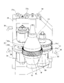
- the chamfering device 30 described above includes a chamfering cutter 31, a deburring cutter 32, support bases 33 and 34, a cutter swivel base 35, a cutter front / rear feed base 42, a cutter front / rear feed motor 44, and the like. It has.
- the chamfering cutter 31 is disposed on a support base 33 that is rotatably supported, and the deburring cutter 32 is disposed on a support base 34 that is rotatably supported.
- the deburring cutter 32 is moved up and down by a piston (not shown) incorporated in the support base 34 and a pressing means (not shown).
- These support bases 33 and 34 are fixed to the tip 35b side of a cutter swivel base (one feed base) 35.
- Fixing handles 38 and 39 for fixing the chamfering cutter 31 and the deburring cutter 32 to the cutter rotating table 35 are attached to the side portions of the cutter rotating table 35, respectively.
- height adjustment screws 36, 37 a, and 37 b for adjusting the height positions of the chamfering cutter 31 and the deburring cutter 32 are attached to the upper portion of the cutter swivel base 35 on the tip 35 b side. Therefore, the height adjusting screws 36, 37a, and 37b adjust the height direction positions of the chamfering cutter main bodies 31a and 31b described later and the heights of the deburring cutter main bodies 32a and 32b described later according to the height of the workpiece W. The position in the vertical direction can be adjusted.
- a hole 35 a is formed on the base end 35 c side of the cutter swivel base 35. It is arranged in a state where the front end 42b side of the cutter front / rear feed base (the other feed base) 42 is inserted into the hole 35a, and the end surface on the rear end side of the cutter swivel base 35 and the cutter front / rear feed base in the hole 35a. It arrange
- the cutter swivel base 35 is supported by the cutter front / rear feed base 42 via the swivel axis 41, and is supported by the cutter front / rear feed base 42 so as to be pivotable about the swivel axis 41 as a swivel center.
- the cutter front and rear feed base 42 is disposed on the base 43.
- a cutter back-and-forth feed motor 44 is fixed to one end side of the base 43.
- the front / rear feed motor 44 has a shaft body 45 extending toward the cutter swivel base 35. However, the longitudinal feed motor 44 is arranged so that the chamfering cutter 31 is positioned in the extending direction of the shaft body 45.
- the shaft body 45 is disposed so as to pass through a hole 42 a formed in the cutter front-rear feed base 42.
- a cylindrical member 46 (hereinafter referred to as a cylindrical member) 46 having a threaded portion on the inner surface is fixed near the end surface of the cutter front / rear feed base 42 on the cutter front / rear feed motor 44 side in the hole 42a.
- the threaded portion of the cylindrical member 46 is meshed with the threaded portion formed on the peripheral surface of the shaft body 45. Therefore, when the cutter front / rear feed motor 44 is driven to rotate the shaft body 45 forward and backward, the cutter front / rear feed base 42 slides on the base 43, and the position where the workpiece W and the chamfered cutter 31 mesh with each other, and the workpiece W The position of the cutter swivel 35 is adjusted between the position where the chamfering cutter 31 and the deburring cutter 32 are separated from each other.
- the shaft body 45 and the cylindrical member 46 described above form an axis feeding mechanism.
- a turning force addition spring 50 which is an elastic body, is disposed between the cutter turntable 35 and the cutter front / rear feed stand 42 described above. Specifically, the turning force adding spring 50 is disposed in a hole 35 d formed in the cutter swivel base 35 and a hole 42 e formed in the cutter front-rear feed base 42.
- the reaction force of the cutter front / rear feed base 42 is obtained and the cutter turning base 35 is urged. Therefore, the cutter swivel base 35 is swiveled around the swivel axis 41, and the chamfering cutter 31 fixed to the cutter swivel base 35 is arranged near the workpiece W than the deburring cutter 32.
- the chamfering cutter 31 can be easily brought into contact with the workpiece W before the deburring cutter 32 when the cutter swivel base 35 is moved to the workpiece W side. Furthermore, when the workpiece W and the chamfering cutter 31 are engaged with each other, even if the tooth crests of the workpiece W and the chamfering cutter 31 are in contact with each other, the chamfering cutter 31 is pushed by the workpiece W by rotating the workpiece W. The tooth crest position of the cutter 31 is changed, and the workpiece W can be meshed with the crest of the chamfering cutter 31 at the crest.
- a turning stopper 51 as a restricting means is fixed to the workpiece W side of the side portion 42c of the cutter front / rear feed base 42.
- the tip 51a of the swivel stopper 51 comes into contact with the hole 35a of the cutter swivel base 35, and the cutter Turning of the turntable 35 (counterclockwise movement in FIG. 4) is restricted. Therefore, the deburring cutter 32 can be positioned with respect to the workpiece W even after the workpiece W and the chamfering cutter 31 are engaged with each other.
- a meshing confirmation detector 48 for detecting a state in which the workpiece W and the chamfering cutter 31 are meshed with each other is disposed on the side portion 42 d of the cutter front-rear feed base 42 via the fixture 47.
- the chamfering cutter 31 described above is composed of a pair of upper and lower chamfering cutter bodies 31a and 31b whose peripheral surfaces are formed in a gear shape.
- the deburring cutter 32 described above has a disk shape and is composed of a pair of upper and lower deburring cutter main bodies 32a and 32b having blades formed on the peripheral surface.
- a diameter L1 of the chamfering cutter 31 is formed larger than a diameter L2 of the deburring cutter 32.
- the chamfering cutter 31 and the deburring cutter 32 are capable of chamfering the gear-worked workpiece W with the chamfering cutter 31 by axially feeding the cutter front / rear feed base 42 to the workpiece W, and the deburring cutter 32. Thus, it is arranged on the cutter swivel 35 so that the burrs of the workpiece W can be removed.
- the chamfering cutter side cutting change amount for the workpiece W is calculated.
- the cutting position of the chamfering cutter 31 is a position where the blade of the chamfering cutter 31 comes into contact with the gear of the workpiece W and is chamfered by the chamfering cutter 31.
- the deburring cutter side cutting change amount for the workpiece W is calculated.
- the cutting position of the deburring cutter 32 is a position where the blade of the deburring cutter 32 contacts the edge of the workpiece W and deburring is performed by the deburring cutter 32.
- the chamfering cutter 31 and the deburring cutter 32 are arranged on the cutter swivel 35 so that the chamfering cutter side cutting variation amount and the deburring cutter side cutting variation amount are substantially the same.
- the maximum shape and the minimum shape of the target workpiece are determined by the specifications of the chamfering cutter 31, the specifications of the deburring cutter 32, and the like.
- the target workpiece is a workpiece that can be processed by the chamfering cutter 31 and the deburring cutter.
- the chamfering cutter 31 With respect to the workpiece over a range from when the diameter of the workpiece that can be processed by the chamfering cutter 31 and the deburring cutter 32 is the maximum to the minimum. And the deburring cutter 32 are substantially the same.
- the chamfering cutter 31 and the deburring cutter 32 can be positioned by the single cutter back-and-forth feed base 42. Therefore, the positions of the cutters 31 and 32 can be adjusted with respect to the workpiece W with a simple structure.
- the apparatus can be miniaturized.
- the relationship between the size of the workpiece, the amount of movement of the chamfering cutter, and the amount of movement of the deburring cutter will be specifically described with reference to FIGS.
- the maximum shape (maximum diameter) of the target workpiece is indicated by a solid line
- the minimum shape (minimum diameter) of the target workpiece is indicated by a one-dot chain line.
- the workpiece W1, the chamfering cutter 31, and the deburring cutter 32 are arranged as shown by a solid line in FIG.
- a distance R1B in the cutting direction between the axis Wc of the workpiece W1 and the axis 32cb of the deburring cutter 32 and a distance R2B in the cutting direction between the axis Wc of the workpiece W1 and the axis 31cb of the chamfering cutter 31 are calculated.
- the workpiece W2 When the workpiece is the minimum shape of the target workpiece, the workpiece W2, the chamfering cutter 31, and the deburring cutter 32 are arranged as shown by a one-dot chain line in FIG.
- the distance R1A in the cutting direction between the axis Wc of the workpiece W2 and the axis 32ca of the deburring cutter 32 and the distance R2A in the cutting direction between the axis Wc of the workpiece W2 and the axis 31ca of the chamfering cutter 31 are calculated.
- the distance Y2 between the shaft centers 31ca and 31cb of the cutter 31 is calculated and calculated so as to satisfy the following expression (1).
- the workpiece can be processed over the range from the maximum to the minimum diameter of the workpiece that can be processed by the chamfering cutter 31 and the deburring cutter 32.
- the feed amount of the chamfering cutter 31 and the feed amount of the deburring cutter 32 with respect to W are the same.
- Fig. 6 (a) shows the case where the workpiece is arranged at the position near the chamfering cutter.
- the distances R1A, R1B, R2A, R2B in the cutting direction of the deburring cutter and chamfering cutter are set to the minimum shape and the maximum shape of the target workpiece and are arranged at positions Y11, Y12 different from Y1, Y2, formula (1) And X11> X12 as is clear from the figure.
- Fig. 6 (b) shows the case where the workpiece is arranged at the position near the deburring cutter side.
- the distance R1A, R1B, R2A, R2B in the cutting direction of the deburring cutter and the chamfering cutter is set to the minimum shape and the maximum shape of the target workpiece and arranged at positions Y21, Y22 different from Y1, Y2, formula (1) And X21 ⁇ X22 as apparent from the figure.
- the workpiece W extends over the range from when the diameter of the target workpiece is maximum to minimum.
- the feed amount of the chamfering cutter 31 and the feed amount of the deburring cutter 32 can be made substantially the same.
- the chamfering cutter 31 and the deburring cutter 32 can be positioned by one cutter front-and-rear feed base 42. Therefore, the position of each cutter can be adjusted with respect to the workpiece with a simple structure.
- the apparatus can be miniaturized.
- the chamfering cutter 31 and the deburring cutter 32 are located apart from the gear-worked workpiece W as shown in FIG.
- the cutter front / rear feed motor 44 is driven to rotate the shaft body 45, and the cutter front / rear feed base 42 is moved to a position where the gear of the workpiece W and the blade of the chamfered cutter 31 do not interfere with each other. Is moved (moved forward) to the workpiece W side.
- the workpiece W is rotated to position the cutter back-and-forth feed base 42 at the meshing confirmation position. Specifically, the cutter front / rear feed base 42 is moved to the workpiece W side.
- the cutter swivel base 35 is swiveled around the swiveling shaft 41 and the chamfering cutter 31 is pushed back. It is.
- the tip 48a of the meshing confirmation detector 48 is not in contact with the inner surface of the hole 35a of the cutter swivel base 35 and is turned OFF.
- the force to be pushed back is reduced to such an extent that the work W is not damaged by the turning force addition spring 50. That is, the impact at the time of contact between the workpiece W and the chamfering cutter 31 is reduced by the turning force adding spring 50.
- the turning stopper 51 is arranged at a position where it does not act, and the force of the shaft body 45 does not act.
- the cutter swivel base 35 is swung around the swivel shaft 41 by the swivel force addition spring 50, and the engagement between the workpiece W and the chamfered cutter 31 is completed.
- the tip 48a of the meshing confirmation detector 48 comes into contact with the hole 35a of the cutter swivel base 35 and is turned on (meshing is completed).
- the cutter back-and-forth feed base 42 is moved forward to the work W side and arranged.
- the chamfering cutter 31 is disposed at the edge of the workpiece W.
- the turning of the cutter swivel base 35 is regulated by the swivel stopper 51, and the chamfering processing force is passed through the swivel stopper 51, the cutter front / rear feed base 42, the cylindrical member 46, and the shaft body 45, and the cutter front / rear feed motor 44.
- the deburring cutter 32 is pressed against the workpiece W (the deburring cutter main body 32a is pressed down and the deburring cutter main body 32b is pressed up), and the burr generated by the chamfering process is removed.
- the chamfering cutter 31 and the deburring cutter 32 are simultaneously acted on the workpiece W, and the chamfering of the gear of the workpiece W and the deburring of the edge of the workpiece W are performed simultaneously.
- the flat teeth of the chamfering cutter 31 are pressed against the upper and lower edges W T , W L of the helical gear of the workpiece W (see the thick line portion of the workpiece W in FIG. 3) and plastically deformed. The portion is chamfered.
- burrs are generated on the upper and lower sides of the workpiece W. This burr is cut and removed by the teeth of the deburring cutter 32.
- the chamfering cutter 31 and the deburring cutter 32 are arranged on the same cutter swivel 35, it is not necessary to individually position the chamfering cutter 31 and the deburring cutter 32, and the work is facilitated. Further, the structure itself is simple, and an increase in equipment cost can be suppressed.
- the chamfering cutter 31, the deburring cutter 32 having a diameter L 2 different from the diameter L 1 of the chamfering cutter 31, the chamfering cutter 31 and the deburring cutter 32 are rotatably supported, and the chamfering cutter 30 is chamfered.
- a cutter swivel 35 and a cutter back-and-forth feed base 42 that can adjust the positions of the cutter 31 and the deburring cutter 32 with respect to the work W are provided.
- the turning stopper 51 it may be necessary to set an axial center distance slightly different from that of the deburring cutter 32, but it can be set by adjusting the turning stopper 51. Further, the reduction of the outer shape due to the cutting of the deburring cutter 32 can also be handled by adjusting the turning stopper 51 in the same manner.
- a hobbing machine is used as the gear processing machine 100, but a facility in which a chamfering device is installed in a gear processing machine other than the hobbing machine may be used. Even with such equipment, the same effects as the gear processing machine described above can be obtained.
- the chamfering device 30 that performs chamfering and deburring on the workpiece W that has been processed with a helical gear has been described. However, by changing the tooth shape of the chamfering cutter, Chamfering and deburring can also be performed.
- the chamfering apparatus 30 including the pair of chamfering cutter main bodies 31a and 31b and the pair of deburring cutter main bodies 32a and 32b has been described.
- the chamfering cutter main body and the deburring cutter are provided only on the upper side or the lower side of the workpiece.
- a chamfering device in which the main body is arranged may be used.
- the other side of the work can be chamfered and deburred by inverting the front and back of the work. Therefore, even such a chamfering device has the same effects as the chamfering device 30 described above.
- the chamfering cutter 30 including the chamfering cutter 31 and the deburring cutter 32 having the diameter L2 smaller than the diameter L1 of the chamfering cutter 31 has been described.
- the diameter is larger than the diameter of the chamfering cutter and the chamfering cutter. It is also possible to apply to a chamfering apparatus having a deburring cutter having
- the position adjustment of the chamfering cutter and the deburring cutter with respect to the workpiece can be easily performed with a simple structure, it can be used beneficially in the machine tool industry and the like.
Priority Applications (4)
| Application Number | Priority Date | Filing Date | Title |
|---|---|---|---|
| EP20100847965 EP2548684A1 (en) | 2010-03-15 | 2010-10-06 | Chamfering device and gear processing machine provided therewith |
| BR112012010109A BR112012010109A2 (pt) | 2010-03-15 | 2010-10-06 | dispositivo de chanfragem, e, máquina de corte de engrenagem |
| CN201080048373.6A CN102596473B (zh) | 2010-03-15 | 2010-10-06 | 倒角装置及具备该倒角装置的齿轮加工机 |
| US13/504,552 US9120166B2 (en) | 2010-03-15 | 2010-10-06 | Chamfering device and gear processing machine provided therewith |
Applications Claiming Priority (2)
| Application Number | Priority Date | Filing Date | Title |
|---|---|---|---|
| JP2010057009A JP5072993B2 (ja) | 2010-03-15 | 2010-03-15 | 面取り装置およびそれを具備する歯車加工機 |
| JP2010-057009 | 2010-03-15 |
Publications (1)
| Publication Number | Publication Date |
|---|---|
| WO2011114558A1 true WO2011114558A1 (ja) | 2011-09-22 |
Family
ID=44648678
Family Applications (1)
| Application Number | Title | Priority Date | Filing Date |
|---|---|---|---|
| PCT/JP2010/067504 WO2011114558A1 (ja) | 2010-03-15 | 2010-10-06 | 面取り装置およびそれを具備する歯車加工機 |
Country Status (7)
| Country | Link |
|---|---|
| US (1) | US9120166B2 (zh) |
| EP (1) | EP2548684A1 (zh) |
| JP (1) | JP5072993B2 (zh) |
| CN (1) | CN102596473B (zh) |
| BR (1) | BR112012010109A2 (zh) |
| TW (1) | TWI422449B (zh) |
| WO (1) | WO2011114558A1 (zh) |
Cited By (3)
| Publication number | Priority date | Publication date | Assignee | Title |
|---|---|---|---|---|
| EP2623244A3 (de) * | 2012-02-03 | 2017-08-23 | LIEBHERR-VERZAHNTECHNIK GmbH | Verfahren zum Betrieb einer Werkzeugmaschine sowie Werkzeugmaschine |
| US20170326662A1 (en) * | 2014-12-10 | 2017-11-16 | Gleason-Pfauter Maschinenfabrik Gmbh | Method for machining a set of teeth, tool arrangement, and tooth-cutting machine |
| CN110091003A (zh) * | 2019-05-14 | 2019-08-06 | 柳州欧维姆机械股份有限公司 | 一种圆形工件双面外圆倒角设备 |
Families Citing this family (13)
| Publication number | Priority date | Publication date | Assignee | Title |
|---|---|---|---|---|
| DE102011006993A1 (de) * | 2011-04-07 | 2012-10-11 | Mag Modul Verzahntechnik Gmbh | Verfahren zur Herstellung von Verzahnung an Werkstücken |
| JP5691944B2 (ja) | 2011-08-31 | 2015-04-01 | コベルコ建機株式会社 | 上部旋回体の機器支持構造 |
| JP2013212551A (ja) * | 2012-04-02 | 2013-10-17 | Asano Gear Co Ltd | 歯車加工装置および歯車加工方法 |
| JP5994057B2 (ja) * | 2012-08-02 | 2016-09-21 | 株式会社 神崎高級工機製作所 | 歯車加工装置 |
| DE102013212432B4 (de) * | 2013-06-27 | 2015-11-05 | Felsomat Gmbh & Co. Kg | Wälzfräsmaschine mit Schwenkarm, an dem eine Anfasvorrichtung und wenigstens ein Schneidwerkzeug angeordnet ist |
| DE102013218542B4 (de) * | 2013-09-16 | 2015-09-24 | Felsomat Gmbh & Co Kg | Verfahren zum Anfasen und Glätten von verzahnten Werkstücken und zugehörige Bearbeitungsstation |
| JP6231383B2 (ja) * | 2013-12-27 | 2017-11-15 | 株式会社 神崎高級工機製作所 | 加工システム及び加工具の交換方法 |
| DE102014010824B4 (de) * | 2014-07-23 | 2016-09-08 | Emag Holding Gmbh | Vorrichtung zum Anfasen und Entgraten verzahnter Werkstücke |
| DE102014013230A1 (de) * | 2014-09-05 | 2016-03-10 | Gleason-Pfauter Maschinenfabrik Gmbh | Verfahren zum Bearbeiten einer Verzahnung, Bearbeitungswerkzeug und Werkzeugmaschine |
| CN109153088B (zh) * | 2016-05-19 | 2021-06-29 | 格里森工场 | 齿轮的齿顶面倒角 |
| CN106217054B (zh) * | 2016-08-31 | 2023-07-07 | 浙江飞宇自动化科技股份有限公司 | 一种轴承钢圈自动成型机 |
| CN113070761B (zh) * | 2021-04-26 | 2022-04-12 | 常熟星祥益精密制造有限公司 | 一种高端装备制造零件倒角设备 |
| CN116652616B (zh) * | 2023-07-31 | 2023-09-26 | 冰轮环境技术股份有限公司 | 一种多功能管材加工装置 |
Citations (7)
| Publication number | Priority date | Publication date | Assignee | Title |
|---|---|---|---|---|
| JPS6074913U (ja) * | 1983-10-28 | 1985-05-25 | 三菱重工業株式会社 | 複合ホブ盤 |
| JPS6278220U (zh) * | 1985-10-31 | 1987-05-19 | ||
| JPH0899221A (ja) * | 1994-09-30 | 1996-04-16 | Ando Electric Co Ltd | 歯車のバニッシング装置 |
| JP3056882U (ja) * | 1997-08-22 | 1999-03-05 | ザ グリーソン ワークス | 歯車の歯の端縁を面取り、バリ取りする装置 |
| WO2006083767A2 (en) * | 2005-02-04 | 2006-08-10 | Magna Drivetrain Of America, Inc. | Multiple operation gear manufacturing apparatus with common work axis |
| JP2006224228A (ja) * | 2005-02-16 | 2006-08-31 | Kashifuji:Kk | 歯車加工装置 |
| JP2009039800A (ja) * | 2007-08-07 | 2009-02-26 | Mitsubishi Heavy Ind Ltd | 面取り装置およびそれを具備する歯車加工機 |
Family Cites Families (2)
| Publication number | Priority date | Publication date | Assignee | Title |
|---|---|---|---|---|
| JPH0356882U (zh) * | 1989-10-04 | 1991-05-31 | ||
| US6757949B2 (en) * | 2002-03-27 | 2004-07-06 | New Venture Gear, Inc. | Combination gear hobber, chamfer/debur and shaver apparatus and method |
-
2010
- 2010-03-15 JP JP2010057009A patent/JP5072993B2/ja active Active
- 2010-10-06 EP EP20100847965 patent/EP2548684A1/en not_active Withdrawn
- 2010-10-06 BR BR112012010109A patent/BR112012010109A2/pt not_active IP Right Cessation
- 2010-10-06 WO PCT/JP2010/067504 patent/WO2011114558A1/ja active Application Filing
- 2010-10-06 US US13/504,552 patent/US9120166B2/en not_active Expired - Fee Related
- 2010-10-06 CN CN201080048373.6A patent/CN102596473B/zh active Active
- 2010-10-20 TW TW99135808A patent/TWI422449B/zh active
Patent Citations (7)
| Publication number | Priority date | Publication date | Assignee | Title |
|---|---|---|---|---|
| JPS6074913U (ja) * | 1983-10-28 | 1985-05-25 | 三菱重工業株式会社 | 複合ホブ盤 |
| JPS6278220U (zh) * | 1985-10-31 | 1987-05-19 | ||
| JPH0899221A (ja) * | 1994-09-30 | 1996-04-16 | Ando Electric Co Ltd | 歯車のバニッシング装置 |
| JP3056882U (ja) * | 1997-08-22 | 1999-03-05 | ザ グリーソン ワークス | 歯車の歯の端縁を面取り、バリ取りする装置 |
| WO2006083767A2 (en) * | 2005-02-04 | 2006-08-10 | Magna Drivetrain Of America, Inc. | Multiple operation gear manufacturing apparatus with common work axis |
| JP2006224228A (ja) * | 2005-02-16 | 2006-08-31 | Kashifuji:Kk | 歯車加工装置 |
| JP2009039800A (ja) * | 2007-08-07 | 2009-02-26 | Mitsubishi Heavy Ind Ltd | 面取り装置およびそれを具備する歯車加工機 |
Cited By (5)
| Publication number | Priority date | Publication date | Assignee | Title |
|---|---|---|---|---|
| EP2623244A3 (de) * | 2012-02-03 | 2017-08-23 | LIEBHERR-VERZAHNTECHNIK GmbH | Verfahren zum Betrieb einer Werkzeugmaschine sowie Werkzeugmaschine |
| US20170326662A1 (en) * | 2014-12-10 | 2017-11-16 | Gleason-Pfauter Maschinenfabrik Gmbh | Method for machining a set of teeth, tool arrangement, and tooth-cutting machine |
| US10239139B2 (en) * | 2014-12-10 | 2019-03-26 | Gleason-Pfauter Maschinenfabrik Gmbh | Method for machining a set of teeth, tool arrangement, and tooth-cutting machine |
| CN110091003A (zh) * | 2019-05-14 | 2019-08-06 | 柳州欧维姆机械股份有限公司 | 一种圆形工件双面外圆倒角设备 |
| CN110091003B (zh) * | 2019-05-14 | 2024-04-05 | 柳州欧维姆机械股份有限公司 | 一种圆形工件双面外圆倒角设备 |
Also Published As
| Publication number | Publication date |
|---|---|
| JP5072993B2 (ja) | 2012-11-14 |
| EP2548684A1 (en) | 2013-01-23 |
| JP2011189449A (ja) | 2011-09-29 |
| CN102596473A (zh) | 2012-07-18 |
| CN102596473B (zh) | 2015-06-17 |
| US20120251258A1 (en) | 2012-10-04 |
| TW201139018A (en) | 2011-11-16 |
| BR112012010109A2 (pt) | 2016-06-07 |
| TWI422449B (zh) | 2014-01-11 |
| US9120166B2 (en) | 2015-09-01 |
Similar Documents
| Publication | Publication Date | Title |
|---|---|---|
| JP5072993B2 (ja) | 面取り装置およびそれを具備する歯車加工機 | |
| JP5192748B2 (ja) | 面取り装置およびそれを具備する歯車加工機 | |
| JP4648219B2 (ja) | 歯車研削盤 | |
| JP5761577B2 (ja) | クラウンギヤの製造装置及び製造方法 | |
| KR101254793B1 (ko) | 베벨기어 톱니선단을 모따기하거나 귀따기하는 베벨기어 절삭장치와 그 방법 | |
| US8257144B2 (en) | Neck portion grinding apparatus and grinding device employed in the neck portion grinding apparatus | |
| US20130121779A1 (en) | Method and device for machining tooth edges | |
| CN1721114A (zh) | 齿轮磨床 | |
| US9821392B2 (en) | Rotary machining apparatus and machining method using the same | |
| JP2010260171A (ja) | 歯切りされた被加工歯車の歯縁を機械加工する方法及び装置 | |
| US20160228961A1 (en) | Internal-gear machining device and internal-gear machining method | |
| CN104338988B (zh) | 切削工具 | |
| TW201249574A (en) | Gear grinding method | |
| WO2014148390A1 (ja) | 歯車加工装置 | |
| JP2010184324A (ja) | 再研磨方法 | |
| JP4377449B1 (ja) | 板ガラス加工装置 | |
| JP6668042B2 (ja) | 歯車用研磨体を用いた歯車研磨方法 | |
| JP2010184320A (ja) | 歯車加工方法 | |
| JP6815913B2 (ja) | ウォーム加工装置、ウォーム加工方法及びウォーム | |
| JP5877467B2 (ja) | 歯車の歯形を面取り加工する方法 | |
| JPH1086017A (ja) | 歯車の加工方法および歯車加工用バリ取り装置 | |
| JP4014833B2 (ja) | バリ取り装置およびバリ取り方法 | |
| JP6087596B2 (ja) | 研削方法 | |
| JP7331510B2 (ja) | 砥石による研削加工方法 | |
| JP2009034788A (ja) | 歯車加工装置 |
Legal Events
| Date | Code | Title | Description |
|---|---|---|---|
| WWE | Wipo information: entry into national phase |
Ref document number: 201080048373.6 Country of ref document: CN |
|
| 121 | Ep: the epo has been informed by wipo that ep was designated in this application |
Ref document number: 10847965 Country of ref document: EP Kind code of ref document: A1 |
|
| WWE | Wipo information: entry into national phase |
Ref document number: 2010847965 Country of ref document: EP |
|
| WWE | Wipo information: entry into national phase |
Ref document number: 1035/MUMNP/2012 Country of ref document: IN |
|
| WWE | Wipo information: entry into national phase |
Ref document number: 13504552 Country of ref document: US |
|
| WWE | Wipo information: entry into national phase |
Ref document number: 1201002000 Country of ref document: TH |
|
| NENP | Non-entry into the national phase |
Ref country code: DE |
|
| REG | Reference to national code |
Ref country code: BR Ref legal event code: B01A Ref document number: 112012010109 Country of ref document: BR |
|
| ENP | Entry into the national phase |
Ref document number: 112012010109 Country of ref document: BR Kind code of ref document: A2 Effective date: 20120427 |