WO2011111486A1 - 把持装置 - Google Patents
把持装置 Download PDFInfo
- Publication number
- WO2011111486A1 WO2011111486A1 PCT/JP2011/053232 JP2011053232W WO2011111486A1 WO 2011111486 A1 WO2011111486 A1 WO 2011111486A1 JP 2011053232 W JP2011053232 W JP 2011053232W WO 2011111486 A1 WO2011111486 A1 WO 2011111486A1
- Authority
- WO
- WIPO (PCT)
- Prior art keywords
- fine hairs
- gripping
- holding member
- gripping device
- fine
- Prior art date
- Legal status (The legal status is an assumption and is not a legal conclusion. Google has not performed a legal analysis and makes no representation as to the accuracy of the status listed.)
- Ceased
Links
Images



Classifications
-
- H—ELECTRICITY
- H10—SEMICONDUCTOR DEVICES; ELECTRIC SOLID-STATE DEVICES NOT OTHERWISE PROVIDED FOR
- H10P—GENERIC PROCESSES OR APPARATUS FOR THE MANUFACTURE OR TREATMENT OF DEVICES COVERED BY CLASS H10
- H10P72/00—Handling or holding of wafers, substrates or devices during manufacture or treatment thereof
- H10P72/70—Handling or holding of wafers, substrates or devices during manufacture or treatment thereof for supporting or gripping
- H10P72/72—Handling or holding of wafers, substrates or devices during manufacture or treatment thereof for supporting or gripping using electrostatic chucks
- H10P72/722—Details of electrostatic chucks
-
- H—ELECTRICITY
- H02—GENERATION; CONVERSION OR DISTRIBUTION OF ELECTRIC POWER
- H02N—ELECTRIC MACHINES NOT OTHERWISE PROVIDED FOR
- H02N13/00—Clutches or holding devices using electrostatic attraction, e.g. using Johnson-Rahbek effect
Definitions
- the present invention relates to a gripping device.
- biomimetics referred to as biomimetic technology, etc.
- biomimetic technology etc.
- An example of this is the ability to attach geckos when walking on a wall or ceiling with their extremities.
- van der Waals force is mounting electronic components (chip components) on a printed circuit board.
- a method using vacuum suction is generally used to hold a chip component at the tip of a robot arm or the like, but the chip component is becoming minute every year, and it is becoming difficult to hold the chip component by vacuum suction.
- the use of van der Waals force can be considered as a gripping method instead of the conventional method such as vacuum suction.
- Patent Document 1 discloses an adsorption device that has a longitudinal shape imitating the cilia of a gecko's sole and obtains a van der Waals force. This length has a structure in which a positive conductor and a negative conductor are blocked by an insulator.
- Patent Document 2 discloses an object handling module having an adsorption structure having anisotropic hairs.
- the hair-like portion is formed obliquely with respect to the base portion, and the tip of the hair-like portion is also inclined.
- the object handling module is configured to adsorb the object by bringing the hairs into contact with each other from the tangential direction of the contact surface of the object.
- Patent Document 3 discloses that fine particles such as dust attached to a nanostructure having a plurality of protrusions by van der Waals force are separated from the nanostructure by applying a potential to the nanostructure. Patent Document 3 also discloses the use of this nanostructure for moving an object.
- JP 2007-236174 A International Publication No. 2007/121450 US Patent Application Publication No. 2008/0169003
- Patent Document 1 the longitudinal length described in Patent Document 1 is a complicated structure that electrically insulates a conductor such as a metal that becomes both positive and negative electrodes, and it is not easy to manufacture, and a specific method thereof is not shown. .
- the object handling module described in Patent Document 2 is configured on the assumption that the object to be handled has a certain size, and has a drawback that it is difficult to handle a minute object.
- the van der Waals force is adjusted by applying a variable level potential to the nanostructure.
- the electrostatic force generated by the electric field when the potential is applied to the nanostructure also affects the adsorption force. Therefore, it is not easy to control the adsorption force with the contact surface only with either positive or negative potential.
- the present invention has been made in view of the above-described problems, and an object of the present invention is to provide a gripping device that can freely release an object gripped by van der Waals force. .
- a holding member having a plurality of fine hairs and formed of a dielectric material;
- a moving mechanism for moving the holding member relative to the object such that the plurality of fine hairs are in contact with the object;
- An electrode provided on a side opposite to the side having the plurality of fine hairs of the holding member;
- a drive circuit that applies a voltage that alternately changes polarity over time to the electrodes when the plurality of fine hairs release the object from a state of gripping the object by van der Waals force. Gripping device.
- the object gripped by van der Waals force can be freely released.
- FIG. 1 It is a figure which shows schematic structure of the holding part and control part of embodiment which concerns on this invention. It is a figure showing a schematic structure of a grasping device of an embodiment concerning the present invention. It is a perspective view of a holding member provided with fine hair. It is a figure which shows the electrical state of the holding part which is contacting the holding
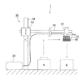
- FIG. 2 shows an overall schematic configuration of the gripping device 1 according to the embodiment of the present invention.
- the gripping device 1 includes a gripping moving unit 30 installed on a gantry.
- the gripping moving unit 30 can move the gripping object 50 gripped by the gripping unit 10 from a position A to a position B on the gantry in two dimensions (can be one-dimensional or three-dimensional).
- the gripping movement unit 30 includes a vertical guide shaft 34, a vertical movement unit 33, a horizontal guide shaft 32, and a horizontal movement unit 31.
- the vertical moving unit 33 can move in the vertical direction along the vertical guide shaft 34 fixed to the gantry, and the horizontal moving unit 31 can move in the horizontal direction along the horizontal guide shaft 32.
- the vertical moving unit 33 holds one end of the horizontal guide shaft 32 so that the horizontal guide shaft 32 is substantially perpendicular to the vertical guide shaft 34.
- Each of the vertical moving unit 33 and the horizontal moving unit 31 includes a driving unit such as a motor, and the horizontal moving unit 31 is held via the holding member 31a by controlling the driving unit by a movement control unit (not shown).
- the holding part 10 to be moved can be freely moved in two dimensions.
- the gripping unit 10 is moved when gripping the gripping target object 50.
- a configuration in which the gripping target object 50 is moved is also conceivable. Any device that moves relatively may be used.
- the grip unit 10 is connected to a control unit 20 that controls the power applied to the grip unit 10, and the grip target 50 can be gripped and released by controlling the applied power.
- the structure of the holding part 10 and the control part 20 is shown in FIG.
- the holding part 10 has a fine structure in which a plurality of fine hairs 12 are formed on a holding member 11 made of a non-conductive material.
- An electrode 13 formed of a conductive material is provided on the opposite side of the holding member 11 from the side where the fine hairs 12 are provided.
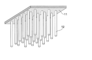
- FIG. 3 shows a state in which the tips of the fine hairs 12 on the side where the fine hairs 12 are in contact with the grasped object 50 face downward.
- the fine hairs 12 are provided so that the heights (lengths) from the lower surface of the holding member 11 to the tips of the fine hairs 12 are substantially uniform.
- the fine hairs 12 are formed of a conductive material, and are formed of CNTs (carbon nanotubes) in the present embodiment. In addition to CNT, metal fibers, conductive polymer fibers, and the like can be used.
- the gripping force when the fine hairs 12 are in contact with the gripping object 50 is the material, cross-sectional area, length, and density of the fine hairs 12 and the apparent contact area (the area that appears to be in contact with the gripping object 50). ). These conditions may be determined as appropriate according to the object to be grasped 50, but are substantially determined mainly from the cross-sectional area (diameter) of the fine hair 12 from the viewpoint of ease of manufacturing and cost. The smaller the diameter of the fine hairs 12, the larger the number of fine hairs 12 per unit area, the more substantial contact points with which the fine hairs 12 come into contact with the grasped object 50, and the grasping force (the vandel of the entire contact portion). (Worth force) becomes larger.
- the diameter and length of the fine hairs 12 may be appropriately determined in consideration of the size, weight, and surface condition such as waviness of the contact surface, ease of manufacture, and manufacturing cost.
- the diameter of the fine hair 12 is preferably 50 ⁇ m or less, and the aspect ratio (length / diameter) is preferably 2.5 or more. When the diameter is 50 ⁇ m or less and the aspect ratio is 2.5 or more, softness and flexibility are sufficient. Can be provided.
- the material of the holding member 11 may be any dielectric non-conductive material that can be thinned, for example, an insulating resin film, preferably having a higher dielectric constant.
- the holding member 11 preferably has a thickness and a dielectric constant that do not cause dielectric breakdown even by an applied voltage of several kV.
- the resin film that can also be used as the holding member 11 include a polyester film, a polycarbonate film, and a polyimide film.
- the holding member 11 having the fine hairs 12 when the holding member 11 is a resin film and the fine hairs 12 are CNTs, the CNTs are vertically oriented and grown on the silicon substrate using a CVD method. There is a method of pressing and transferring the surface portion to a resin film dissolved or coated with an adhesive.
- An electrode 13 is provided on the surface of the holding member 11 opposite to the surface on which the fine hairs 12 are present.
- the electrode 13 can be formed by, for example, vacuum deposition, and the electrode material is not particularly limited. Aluminum, zinc, tin, nickel, copper, silver, and the like can be used alone or in combination to form an alloy or multilayer. Can be used.
- the electrode 13 is insulated from the fine hair 12 and the electric liquid by the holding member 11, even when a voltage is applied to the electrode 13, a current from the fine hair 12 to the grasped object 50 is almost generated. In other words, it is possible to prevent discharge.
- the control unit 20 includes a drive circuit 201 that applies power to the electrode 13, a control circuit 203 that controls the drive circuit 201, and a drive power supply 202 that supplies power to the drive circuit 201 and the control circuit 203.
- the control circuit 203 controls the drive circuit 201 by a control signal or the like from the outside of the control unit 20.
- the control unit 20 may be integrated with a movement control unit that controls the gripping movement unit 30, and may be an overall control device that controls these in a unified manner, or may control the entire gripping device 1. .
- the drive circuit 201 can change the polarity of the voltage applied to the electrode 13 between positive and negative with the potential of the grasped object 50 as a reference potential (for example, GND) based on an instruction from the control circuit 203. Note that the potential of the grasped object 50 is not necessarily set to GND.
- FIGS. 4A to 4C schematically show the electrical state of the gripping portion 10 and the gripping target object 50 while paying attention to one fine hair 12.
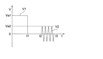
- FIG. 5 shows temporal changes in the voltage applied to the electrode 13. In FIG. 5, the upper side is negative.
- the gripping moving unit 30 detects the gripping unit 10 through the past movement experience of the gripping unit 10, detection of reaction force generated by contact, and the like.
- the fine hairs 12 are moved and pressed so as to approach and contact the grasped object 50 (pressing step).
- control circuit 203 controls the drive circuit 201 to apply a voltage of a predetermined value or more to the electrode 13 based on this instruction.
- the drive circuit 201 applies a negative voltage V ⁇ b> 1 of a predetermined value or more to the electrode 13 under the control of the control circuit 203.
- FIG. 4A shows an electrical state when the voltage V1 is applied to the electrode 13.
- FIG. 13 By applying the negative voltage V ⁇ b> 1 to the electrode 13, positive charges are concentrated in the vicinity of the surface of the holding member 11 on the side where the electrode 13 contacts, and negative charges are concentrated in the vicinity of the opposite surface. Due to the concentrated negative charges, positive charges are concentrated on the holding member 11 side of the fine hairs 12, and negative charges are concentrated near the tip of the opposite side.
- the fine hairs 12 are conductive, they have a certain amount of resistance, and therefore are schematically shown here as being similar to a dielectric.
- a voltage V1 greater than or equal to a predetermined value is temporarily applied to the gripping part 10 (between time t in FIG. 5 from 0 to t1) and stronger than the Van der Waals force between the gripping object 50 and the fine hair 12
- V1 greater than or equal to a predetermined value
- the voltage value Va1 of the voltage V1 applied to the electrode 13 is a static force stronger than the van der Waals force assumed to be generated when the fine hairs 12 are in contact with the grasped object 50 by the movement of the grasping part 10 by the grasping moving part 30.
- the value is greater than the value (predetermined value) at which power is generated.
- the distance between the fine hairs 12 and the object to be grasped 50 is closer, the contact between the fine hairs 12 and the object to be grasped 50 is promoted, and the contact pressure is also increased.
- the tip of the fine hairs 12 can contact and adhere to the back of the recess indicated by the surface roughness of the object to be grasped 50.
- the polarity of van der Waals force generally generated between the grasped object 50 and the fine hairs 12 (the electric dipole in FIG.
- the voltage V1 is a negative value in accordance with the direction. Since the polarity of this van der Waals force is determined by the material of the object to be grasped 50 and the fine hairs 12, it may be desirable to set the voltage V1 to a positive value depending on the material of the object to be grasped 50. Therefore, whether the voltage V1 is a negative value or a positive value may be determined according to the material of the grasped object 50.
- the controller 20 After the attachment of the gripping object 50 and the fine hair 12 as described above by the electrostatic force generated by the application of the voltage V1 to the electrode 13 (after the time t1 shown in FIG. 5 has elapsed), the controller 20 The end of voltage application is instructed. Based on this instruction, the control unit 20 stops applying the voltage V1 to the electrode 13 as shown in FIG. In the state immediately before the application of the voltage V1 is stopped, the end of the fine hair 12 and the surface of the object to be grasped 50 are contact or distance range in which van der Waals force is sufficiently exerted by electrostatic force regardless of the presence of minute irregularities. Is in. For this reason, as shown in FIG.
- an electric dipole (electric dipole) is formed in the vicinity of the surface of the grasped object 50 where the tip of the fine hair 12 and the tip of the fine hair 12 are in contact with or close to each other. Even if the application of the voltage V1 to the electrode 13 is stopped, the gripping unit 10 can sufficiently maintain the gripping state of the gripping object 50 by van der Waals force instead of the electrostatic force. In maintaining this gripping state, it is not necessary to supply power to the gripping unit 10, and the gripping device 1 can contribute to energy reduction.
- the voltage V1 is applied to the electrode 13 during the period up to time t1, but the application of the voltage V1 is not always necessary. Even if the voltage V ⁇ b> 1 is not applied to the electrode 13, if the fine hairs 12 can be sufficiently brought into close contact with the grasped object 50 by the movement of the grasping part 10 by the grasping and moving part 30, it works between the fine hairs 12 and the grasped object 50.
- the object to be grasped 50 can be grasped by Van der Waals force.
- the control circuit 203 applies a positive / negative alternating voltage V 2 having a predetermined amplitude value to the electrode 13.
- the drive circuit 201 applies an alternating voltage V ⁇ b> 2 whose polarity alternately changes with the passage of time to the electrode 13 according to an instruction from the control circuit 203.
- the amplitude value Va2 of the alternating voltage V2 is not more than a value (predetermined value) that generates an electrostatic force equivalent to the van der Waals force assumed to be generated in the attached state, and the electric charge concentrated on the contact surface side of the electrode 13 of the holding member 11 It is desirable that the electrostatic force be less than or equal to the assumed van der Waals force.
- the Van der Waals force assumed here may be an average assumed in a state where the object 50 is held. That is, since the contact state between each of the numerous fine hairs 12 and the grasped object 50 is considered to be different from each other, an average van der Waals force may be assumed as a whole.
- the frequency of the alternating voltage V2 can be determined by experiments or the like in the same manner as described above, the natural frequency of the fine hair 12 can be used as a guide when determining the frequency.
- the gripping part 10 a has an integral structure holding member 11 a and fine hairs 12 a made of a dielectric material.
- An electrode 13 is provided on the surface of the holding member 11a opposite to the surface on which the fine hairs 12a are present, as in the configuration of FIG.
- the dielectric material used for the holding member 11a and the fine hairs 12a is preferably a dielectric material having a dielectric constant that does not break down even by an applied voltage of several kV, and is a material that is flexible and can easily form a fine shape.
- a dielectric material having a dielectric constant that does not break down even by an applied voltage of several kV is preferably a material that is flexible and can easily form a fine shape.
- the integral structure of the holding member 11a and the fine hair 12a it can be manufactured by nanoimprinting, stereolithography, or the like using a rubber material mixed with a dielectric material such as barium titanate as a base material.
- the electrode 13 is insulated from the fine hairs 12a, and even when a voltage is applied to the electrode 13, almost no current is generated from the fine hairs 12a to the grasped object 50, and electric discharge can be made difficult to occur.
- the gripping unit 10 a can similarly hold and release the gripping target object 50. .
- the gripping unit 10 is temporarily disabled by the van der Waals force.
- the grasped object 50 can be reliably released.
- the configuration of the gripping unit 10 is simple, and the application of voltage to the electrode 13 can be achieved with a simple circuit configuration. Therefore, the gripping device 1 can be achieved at low cost. Furthermore, when the gripping part 10 maintains the gripping state of the gripping target object 50, since the van der Waals force is used, power for applying a voltage to the electrode 13 is not required, which can contribute to energy reduction.
Landscapes
- Manipulator (AREA)
Abstract
物体をファンデルワールス力により把持する把持装置において、複数の細毛を有し、誘電体材料で形成された保持部材と、前記複数の細毛が前記物体と接するように、前記保持部材を前記物体に対して相対的に移動させる移動機構と、前記複数の細毛が前記物体をファンデルワールス力により把持している状態から解放するときに、前記電極に時間の経過と共に交互に極性が変わる電圧を印加する駆動回路とを備えた。
Description
本発明は、把持装置に関する。
近年、エネルギー効率の面でバイオミメティックス(生物模倣技術等と称される。)が注目されつつある。その例として、ヤモリが四肢で壁や天井を歩く際の付着能力がある。
ヤモリの天井への付着力はその足の裏面に生えているナノサイズの微細毛によるものである。この付着力は、毛の先端と付着面との間の接触で発生するファンデルワールス力による。人工的にヤモリの足の微細毛を模倣した部材を製作し、この部材の付着力を利用しようとする研究が精力的に行われている。
ファンデルワールス力の利用の例として、プリント基板への電子部品(チップ部品)の実装がある。現状では、例えばロボットアーム等の先端部でのチップ部品の把持は、真空吸着を利用する方法が一般的であるが、チップ部品は年々微小となり、真空吸着による把持が困難な状況となりつつある。真空吸着等の従来方法に替わる把持方法としてファンデルワールス力の利用が考えられる。
特許文献1においては、ヤモリの足裏の繊毛を模した長手を備え、ファンデルワールス力を得る吸着装置が開示されている。この長手は、正の導体と負の導体とが絶縁体により遮断された構造を有している。
特許文献2においては、異方性の毛状部を有する吸着構造を備えた物体取り扱いモジュールが開示されている。この毛状部は、基部に対して斜めに形成されており、また毛状部の先端部も斜めになっている。物体取り扱いモジュールは、この毛状部を対象物の接触面の接線方向から接触させることにより、対象物を吸着するように構成されている。
特許文献3においては、複数の突起を備えるナノ構造にファンデルワールス力によって付着した塵等の微小粒子を、ナノ構造への電位の印加によりナノ構造より引き離すことが開示されている。また、特許文献3は、このナノ構造を物体の移動に用いることについても開示している。
しかしながら、特許文献1に記載の長手は、正負両極となる金属等の導体を電気的に絶縁する複雑な構造であり、これ製造することは容易ではなく、その具体的な方法は示されていない。
特許文献2に記載の物体取り扱いモジュールは、取り扱う物体がある程度の大きさであることを前提とした構成であり、微小な物体を扱うことは困難であるという欠点を有する。
特許文献3に記載のシステムでは、ナノ構造に可変レベルの電位を与えることによりファンデルワールス力を調整するとしているが、ナノ構造に電位を与えた場合の電場により生じる静電力は吸着力にもなり得るので、正負いずれかの電位のみで接触面との吸着力を制御することは容易でない。
本発明は、上記の課題を鑑みてなされたものであって、その目的とするところは、ファンデルワールス力によって把持された対象物を自在に解放することができる把持装置を提供することである。
上記の課題は、以下の構成により解決される。
物体をファンデルワールス力により把持する把持装置において、
複数の細毛を有し、誘電体材料で形成された保持部材と、
前記複数の細毛が前記物体と接するように、前記保持部材を前記物体に対して相対的に移動させる移動機構と、
前記保持部材の前記複数の細毛を有する側とは反対側に設けられた電極と、
前記複数の細毛が前記物体をファンデルワールス力により把持している状態から解放するときに、前記電極に時間の経過と共に交互に極性が変わる電圧を印加する駆動回路とを備えたことを特徴とする把持装置。
複数の細毛を有し、誘電体材料で形成された保持部材と、
前記複数の細毛が前記物体と接するように、前記保持部材を前記物体に対して相対的に移動させる移動機構と、
前記保持部材の前記複数の細毛を有する側とは反対側に設けられた電極と、
前記複数の細毛が前記物体をファンデルワールス力により把持している状態から解放するときに、前記電極に時間の経過と共に交互に極性が変わる電圧を印加する駆動回路とを備えたことを特徴とする把持装置。
本発明によれば、ファンデルワールス力によって把持された対象物を自在に解放することができる。
本発明を実施の形態に基づいて説明するが、本発明は該実施の形態に限らない。
図2に本発明に係る実施の形態の把持装置1の全体の概略構成を示す。把持装置1は、架台の上に設置される把持移動部30を備えている。把持移動部30は、例えば架台の上の位置Aから位置Bに把持部10で把持した把持対象物50を2次元(1次元や3次元とすることもできる)移動可能とするものである。把持移動部30は、垂直ガイド軸34、垂直移動部33、水平ガイド軸32及び水平移動部31を備えている。
垂直移動部33は、架台に固定されている垂直ガイド軸34に沿って垂直方向に移動可能であり、水平移動部31は、水平ガイド軸32に沿って水平方向に移動可能である。垂直移動部33は、水平ガイド軸32が垂直ガイド軸34に対し略直角方向となるように、その一方の端部を保持している。垂直移動部33及び水平移動部31は、それぞれ内部にモータ等の駆動部を備えており、図示しない移動制御部により駆動部を制御することにより、水平移動部31が保持部材31aを介して保持する把持部10を2次元で自在に移動可能とすることができる。尚、本実施の形態では、把持対象物50を把持するに際し、把持部10を移動させるが、把持対象物50を移動する形態のものも考えられ、把持部10は把持対象物50に対して相対的に移動するものであればよい。
把持部10には、把持部10に印加する電力を制御する制御部20が接続され、印加される電力の制御により把持対象物50の把持及び解放を行うことができる。把持部10及び制御部20の構成を図1に示す。
把持部10は、非導電材料で形成された保持部材11に細毛12が複数形成された微細構造体を有している。保持部材11の細毛12が備わる側の反対側には、導電性材料で形成された電極13が設けられている。
保持部材11に細毛12が備わっている様子を部分的に拡大して図3に示す。図3は、細毛12が把持対象物50に接する側である細毛12の先端部を下向きにした状態で示す。図3に示すように、細毛12は、保持部材11の下面から細毛12の先端までの高さ(長さ)がほぼ揃うように設けられている。細毛12は、導電材料で形成されており、本実施の形態ではCNT(カーボンナノチューブ)で形成されている。CNT以外には、金属繊維、導電性高分子繊維等を用いることができる。細毛12が把持対象物50に接した際の把持力は、細毛12の材料、断面積、長さ及び密度と、把持対象物50との見かけ接触面積(接触しているように見えている面積)とで決まると考えられる。これらの条件は、把持対象物50に応じて適宜決めれば良いが、製造の容易性やコストの観点から、実質的には細毛12の断面積(直径)を主体として決められる。細毛12の直径が小さい程、単位面積当たりの細毛12の数を多くすることができ、細毛12が把持対象物50に接触する実質的な接点が多くなり、把持力(接触部分全体のファンデルワールス力)はより大きくなる。
細毛12の直径及び長さは、把持対象物50の大きさ、重さ及び接触表面のうねり等の表面状態、製造の容易さ、製造コスト等を併せて考慮して適宜決めれば良い。細毛12に関しては、その直径は50μm以下が好ましく、そのアスペクト比(長さ/直径)は2.5以上が好ましく、直径を50μm以下でアスペクト比2.5以上とすると柔軟で可撓性を十分に備えたものとすることができる。
このような細毛12は、把持対象物50の接触表面に10μm程度のうねりがあっても、また細毛12自体の高さ(長さ)の製造ばらつきがあっても、把持対象物50の表面に対し、ファンデルワールス力が十分生じるような接触が可能となる。尚、直径の下限とアスペクト比の上限とは特に定めないが、ファンデルワールス力を利用すること、把持対象物50の大きさ及び製造の容易さ等の実用的な観点から自ずと制限され、仕様に応じて適宜定めればよい。
保持部材11の材料は、誘電体の非導電性材料で、薄くすることが可能なものであれば良く、例えば絶縁性の樹脂フィルムがあり、誘電率がより大きいものが好ましい。また、保持部材11は、数kVの印加電圧によっても絶縁破壊されない厚みと誘電率とを有するものが好ましい。保持部材11としても用いることができる樹脂フィルムとしては、例えばポリエステルフィルム、ポリカーボネートフィルム、ポリイミドフィルム等が挙げられる。
細毛12を備える保持部材11の製造の具体例として、保持部材11を樹脂フィルム、細毛12をCNTとすると、シリコン基板上にCVD法を用いてCNTを垂直に配向して成長させ、これを、表面部分を溶解又は接着剤を塗布した樹脂フィルムに押圧・転写する方法がある。
保持部材11の細毛12がある面の反対側の面には、電極13が設けられている。電極13は、例えば真空蒸着により形成することができ、その電極材料としては特に限定されるものではなく、アルミニウム、亜鉛、錫、ニッケル、銅及び銀等を単独で、また組み合わせて合金や多層にして用いることができる。
このように、電極13が保持部材11によって、細毛12と電気液に絶縁された状態とすることにより、電極13に電圧を印加しても、細毛12から把持対象物50への電流がほとんど生じることがなく、放電も生じ難くすることができる。
制御部20は、電極13に電力を付与する駆動回路201、駆動回路201を制御する制御回路203及び駆動回路201と制御回路203とに電力を供給する駆動電源202を備えている。制御回路203は、制御部20の外部からの制御信号等により駆動回路201を制御する。尚、制御部20は、把持移動部30を制御する移動制御部と一体化して、これらを統括して制御する統括制御装置としてもよく、把持装置1の全体を制御するものであってもよい。
駆動回路201は、制御回路203からの指示に基づき、把持対象物50の電位を基準電位(例えばGND)として、電極13に印加する電圧の極性を正負に変化させることができる。尚、把持対象物50の電位を必ずしもGNDとする必要はない。
これまで説明した把持装置1の動作について、図4、5を参照しながら説明する。図4(a)から(c)は、1つの細毛12に注目して把持部10と把持対象物50とにおける電気的状態を模式的に示している。図5は、電極13に印加する電圧の時間的な変化を示している。尚、図5においては、上方が負である。
移動制御部(図示しない)が把持対象物50の把持の指示を受けると、把持移動部30は、把持部10をこれまでの把持部10の移動経験や、接触により生じる反力検知等により、細毛12が把持対象物50に接近・接触するように移動させ、押圧する(押圧工程)。
次に、制御部20に対し把持対象物50の付着が指示されると、この指示に基づき制御回路203は電極13に所定値以上の電圧を印加するように駆動回路201を制御する。
駆動回路201は、図5に示すように、制御回路203の制御により所定値以上の負の電圧V1を電極13に印加する。電極13に電圧V1が印加された際の電気的状態を図4(a)に示す。電極13への負の電圧V1の印加により、保持部材11の電極13が接触する側の面の近傍には正の電荷が集中し、反対側の面の近傍には負の電荷が集中する。この集中した負の電荷によって、細毛12の保持部材11側には正の電荷が集中し、反対側の先端部付近には負の電荷が集中する。なお、細毛12は、導電性ではあるが、ある程度の抵抗を有するため、ここでは模式的に誘電体と同様のものとして示している。
細毛12の先端部付近の負の電荷により把持対象物50の表面には正の電荷が集中する。この細毛12と把持対象物50との電荷により静電力が生じ、把持対象物50は細毛12に付着される(付着工程)。
把持部10に一時的(図5の時間tが0からt1までの間)に所定値以上の電圧V1を付与して、把持対象物50と細毛12との間にファンデルワールス力よりも強力に作用する静電力を生じさせることで、把持対象物50と細毛12との接触を確実なものとすることができる。
電極13に印加する電圧V1の電圧値Va1は、把持移動部30による把持部10の移動により細毛12が把持対象物50に接触した状態で発生すると想定されるファンデルワールス力よりも強力な静電力が生じる値(所定値)以上としている。
発生させた静電力により、細毛12と把持対象物50との距離がより近づき、細毛12と把持対象物50との接触が促進され、接触圧もより大きくなるようになされる。これらは、細毛12と把持対象物50との接触面積がより大きくなるように作用し、例えば把持対象物50の表面粗さで示される凹部の奥まで細毛12の先端が接触・付着できるようになる。尚、電圧V1の電圧値Va1及び印加時間(t=0からt1)は、把持部10が確実(ファンデルワールス力のみで把持対象物50を把持できる状態)に把持対象物50を把持できる電圧値及び時間とし、実験等により定めることができる。
なお、本実施の形態では、細毛12としてCNTを用いているため、把持対象物50と細毛12との間で一般的に生じるファンデルワールス力の極性(図4(b)における電気双極子の向き)に合わせて、電圧V1を負の値としている。このファンデルワールス力の極性は把持対象物50と細毛12との素材で決まるものであるため、把持対象物50の素材によっては電圧V1を正の値とする方が望ましい場合がある。したがって、電圧V1を負の値とするか正の値とするかは、把持対象物50の素材によって決めればよい。
電極13への電圧V1の印加により生じる静電力により、一旦、上記のように把持対象物50と細毛12との付着がなされた後(図5に示す時間t1経過後)、制御部20に対し電圧印加の終了が指示される。この指示に基づき、制御部20は、図5に示すように、電極13への電圧V1の印加を停止する。電圧V1印加の停止直前の状態においては、細毛12端部と把持対象物50の表面とは、微小な凸凹の存在にかかわらず、静電力により、十分にファンデルワールス力の働く接触若しくは距離範囲内にある。このため、図4(b)に示すように、細毛12の先端部分及び細毛12の先端部分が接触又は近接する把持対象物50の表面近傍には、電気双極子(エレクトリック ダイポール:Electric dipole)が発生し、把持部10は、電極13への電圧V1の印加が停止されても、静電力に代わりファンデルワールス力により把持対象物50の把持状態を十分に維持することができる。この把持状態を維持する上で、把持部10への電力の供給は不要であり、把持装置1はエネルギー削減に寄与することができる。
なお、以上の説明では、時間t1までの期間に電圧V1を電極13に印加することにしているが、この電圧V1の印加は必ずしも必要ではない。電圧V1を電極13に印加しなくても把持移動部30による把持部10の移動によって細毛12を把持対象物50に十分に密着させることができれば、細毛12と把持対象物50との間で働くファンデルワールス力によって把持対象物50を把持することができる。
次に、制御部20に対し把持対象物50の解放が指示されると、この指示に基づき、制御回路203は、電極13に所定の振幅値の正負交番電圧V2を印加するように駆動回路201を制御する。図5に示すように、時間t2より、駆動回路201は、制御回路203の指示により、時間の経過と共に交互に極性が変わる交番電圧V2を電極13に印加する。
交番電圧V2の振幅値Va2は、付着状態で発生すると想定されるファンデルワールス力と同等の静電力を生じる値(所定値)以下とし、保持部材11の電極13の接触面側に集中する電荷は、想定されるファンデルワールス力と同等以下の静電力を生じる程度とすることが望ましい。尚、ここで想定されるファンデルワールス力とは、把持対象物50を把持した状態で平均的に想定されるものであればよい。つまり、多数の細毛12のそれぞれと把持対象物50との接触状態は、個々に異なると考えられるため、全体として平均的なファンデルワールス力を想定すればよい。
電極13に印加する電圧の極性を交互反転させると、ファンデルワールス力の発生源の双極子の方向に関わらず、少なくとも電圧変化サイクルの2回に1回はこのファンデルワールス力の全部又は一部を相殺する方向に静電力が発生する。ファンデルワールス力が相殺されると把持対象物50は、重力その他の力の関係により、把持部10から解放されることになる(解放工程)。
尚、交番電圧V2の振幅値及び印加時間(t=t2からt3)は、把持部10が確実に把持対象物50を解放できるように実験等により定めることができる。また、交番電圧V2の周波数は、上記と同様に実験等により定めることができるが、定める上で、細毛12の固有振動数を目安にすることができる。
次に、変形例として、図1の把持部10とは異なる構成の把持部10aを説明する。尚、他の構成、把持・解放動作は上記の説明と同様であるため、説明を省略する。
把持部10aは、図6の模式図に示すように、誘電体材料で形成された一体構造の保持部材11aと細毛12aを有している。保持部材11aの細毛12aがある面側の反対側の面には、図1の構成と同じく、電極13が設けてある。
保持部材11aと細毛12aとの形状は、図1の保持部材11と細毛12と同じなので、説明を省略する。
保持部材11aと細毛12aとに用いられる誘電体材料は、数kVの印加電圧によっても絶縁破壊されない誘電率を有するものが好ましく、また、可撓性があり微細形状を容易に形成できる材料であれば、特に限定されることはない。具体的な保持部材11aと細毛12aとの一体構造の例としては、ゴム材料にチタン酸バリウム等の誘電体を混合したものを基材として、ナノインプリントや光造形等により製造することができる。
電極13は、細毛12aと絶縁された状態となり、電極13に電圧を印加しても、細毛12aから把持対象物50への電流がほとんど生じることがなく、放電も生じ難くすることができる。
図1の構成と同様に、把持部10aの電極13に、制御部20の駆動回路201の出力を接続することで、把持部10aは把持対象物50の把持・解放を同様に行うことができる。
これまでに説明したように、把持部10、10aに所定値以下の振幅値で振動する交番電圧V2を付与することで、ファンデルワールス力を一時的に無力とすることにより、把持部10は把持対象物50の解放を確実に行うことができる。
把持部10の構成は簡単であり、電極13への電圧の付与も、簡単な回路構成で達成可能であるため、把持装置1は安価に達成することができる。更に、把持部10が把持対象物50の把持状態を維持する際は、ファンデルワールス力によるため、電極13に電圧を印加しておく電力を必要とせず、エネルギー削減に寄与することができる。
1 把持装置
10、10a 把持部
11、11a 保持部材
12、12a 細毛
13 電極
20 制御部
201 駆動回路
202 駆動電源
203 制御回路
30 把持移動部
31 水平移動部
32 水平ガイド軸
33 垂直移動部
34 垂直ガイド軸
50 把持対象物
10、10a 把持部
11、11a 保持部材
12、12a 細毛
13 電極
20 制御部
201 駆動回路
202 駆動電源
203 制御回路
30 把持移動部
31 水平移動部
32 水平ガイド軸
33 垂直移動部
34 垂直ガイド軸
50 把持対象物
Claims (7)
- 物体をファンデルワールス力により把持する把持装置において、
複数の細毛を有し、誘電体材料で形成された保持部材と、
前記複数の細毛が前記物体と接するように、前記保持部材を前記物体に対して相対的に移動させる移動機構と、
前記保持部材の前記複数の細毛を有する側とは反対側に設けられた電極と、
前記複数の細毛が前記物体をファンデルワールス力により把持している状態から解放するときに、前記電極に時間の経過と共に交互に極性が変わる電圧を印加する駆動回路とを備えたことを特徴とする把持装置。 - 前記複数の細毛は、前記誘電体材料により前記保持部材と一体構造で形成されていることを特徴とする請求項1に記載の把持装置。
- 前記複数の細毛は、導電材料で形成されていることを特徴とする請求項1に記載の把持装置。
- 前記複数の細毛は、カーボンナノチューブで形成されていることを特徴とする請求項3に記載の把持装置。
- 前記複数の細毛は、断面の直径が50μm以下でアスペクト比2.5以上であることを特徴とする請求項1から4の何れか一項に記載の把持装置。
- 前記駆動回路は、前記複数の細毛が前記物体を把持する際に、静電力を発生するための所定の電圧を前記電極に印加することを特徴とする請求項1から5の何れか一項に記載の把持装置。
- 前記移動機構は、前記保持部材を垂直方向に移動させる垂直移動部と、前記保持部材を水平方向に移動させる水平移動部とを有することを特徴とする請求項1から6の何れか一項に記載の把持装置。
Applications Claiming Priority (2)
| Application Number | Priority Date | Filing Date | Title |
|---|---|---|---|
| JP2010050341 | 2010-03-08 | ||
| JP2010-050341 | 2010-03-08 |
Publications (1)
| Publication Number | Publication Date |
|---|---|
| WO2011111486A1 true WO2011111486A1 (ja) | 2011-09-15 |
Family
ID=44563311
Family Applications (1)
| Application Number | Title | Priority Date | Filing Date |
|---|---|---|---|
| PCT/JP2011/053232 Ceased WO2011111486A1 (ja) | 2010-03-08 | 2011-02-16 | 把持装置 |
Country Status (1)
| Country | Link |
|---|---|
| WO (1) | WO2011111486A1 (ja) |
Cited By (1)
| Publication number | Priority date | Publication date | Assignee | Title |
|---|---|---|---|---|
| JP2014107319A (ja) * | 2012-11-26 | 2014-06-09 | Canon Inc | 接着力が制御可能な接着用部材 |
Citations (5)
| Publication number | Priority date | Publication date | Assignee | Title |
|---|---|---|---|---|
| JP2001358193A (ja) * | 2000-06-13 | 2001-12-26 | Ulvac Japan Ltd | 静電吸着装置、基板搬送装置、真空処理装置及び基板保持方法 |
| JP2002118164A (ja) * | 2000-10-05 | 2002-04-19 | Seiko Epson Corp | 静電チャック、半導体処理装置及び静電チャックの脱離方法 |
| JP2007236174A (ja) * | 2006-02-27 | 2007-09-13 | Oriol Lopez Berengueres Jose | 吸着装置 |
| JP2009117441A (ja) * | 2007-11-02 | 2009-05-28 | Creative Technology:Kk | ワーク保持装置 |
| JP2010021510A (ja) * | 2008-06-13 | 2010-01-28 | Canon Anelva Corp | 基板保持装置およびプラズマ処理装置 |
-
2011
- 2011-02-16 WO PCT/JP2011/053232 patent/WO2011111486A1/ja not_active Ceased
Patent Citations (5)
| Publication number | Priority date | Publication date | Assignee | Title |
|---|---|---|---|---|
| JP2001358193A (ja) * | 2000-06-13 | 2001-12-26 | Ulvac Japan Ltd | 静電吸着装置、基板搬送装置、真空処理装置及び基板保持方法 |
| JP2002118164A (ja) * | 2000-10-05 | 2002-04-19 | Seiko Epson Corp | 静電チャック、半導体処理装置及び静電チャックの脱離方法 |
| JP2007236174A (ja) * | 2006-02-27 | 2007-09-13 | Oriol Lopez Berengueres Jose | 吸着装置 |
| JP2009117441A (ja) * | 2007-11-02 | 2009-05-28 | Creative Technology:Kk | ワーク保持装置 |
| JP2010021510A (ja) * | 2008-06-13 | 2010-01-28 | Canon Anelva Corp | 基板保持装置およびプラズマ処理装置 |
Cited By (1)
| Publication number | Priority date | Publication date | Assignee | Title |
|---|---|---|---|---|
| JP2014107319A (ja) * | 2012-11-26 | 2014-06-09 | Canon Inc | 接着力が制御可能な接着用部材 |
Similar Documents
| Publication | Publication Date | Title |
|---|---|---|
| KR102410081B1 (ko) | 로봇 그리퍼 | |
| CN103780137B (zh) | 一种振动开关式摩擦发电机和摩擦发电方法 | |
| US8982531B2 (en) | Additional force augmented electroadhesion | |
| JP6356791B2 (ja) | スライド摩擦式発電機、発電方法及びベクトル変位センサ | |
| US20170236990A1 (en) | Energy harvester | |
| JP2010530810A5 (ja) | ||
| JP2017135775A (ja) | 発電素子及び発電装置 | |
| WO2011111486A1 (ja) | 把持装置 | |
| JP4808149B2 (ja) | 静電チャック | |
| KR101557238B1 (ko) | 액체방울을 이용한 발전소자 | |
| KR20140115167A (ko) | 전사 인쇄용 스탬프 구조체 및 이를 이용한 전사 인쇄 방법 | |
| US11926041B2 (en) | Three-dimensional electromechanical adhesive surface structure capable of adhesive force manipulation and tactile sensing, design and manufacturing method thereof using 3D printing | |
| JP6343618B2 (ja) | 搬送装置 | |
| CN103780140A (zh) | 一种共面式摩擦发电机 | |
| JP6171203B2 (ja) | ラベル貼付装置 | |
| KR20200007362A (ko) | 일체형 전극구조체가 구비된 마찰대전 발전기 | |
| CN210421782U (zh) | 一种磁粘性体发电地板 | |
| KR102122776B1 (ko) | 전기장을 이용하여 탈부착이 가능한 건식 접착 구조물 | |
| US11870372B2 (en) | Flexible and hybrid energy harvesting device combining piezoelectric and electrostatic conversions | |
| CN113285628B (zh) | 基于微间隙电晕放电的高输出性能多脉冲发电机及系统 | |
| TWI589358B (zh) | 帶電粉體導引裝置 | |
| JP4419579B2 (ja) | 静電チャック | |
| WO2024143432A1 (ja) | 静電チャック | |
| Choi et al. | Power generating characteristics of zinc oxide nanorods grown on a flexible substrate by a hydrothermal method | |
| KR20220005897A (ko) | 모양 및 배치의 변화에 따른 3차원 전자기계적 접착 표면 특성 제어 |
Legal Events
| Date | Code | Title | Description |
|---|---|---|---|
| 121 | Ep: the epo has been informed by wipo that ep was designated in this application |
Ref document number: 11753148 Country of ref document: EP Kind code of ref document: A1 |
|
| NENP | Non-entry into the national phase |
Ref country code: DE |
|
| 122 | Ep: pct application non-entry in european phase |
Ref document number: 11753148 Country of ref document: EP Kind code of ref document: A1 |
|
| NENP | Non-entry into the national phase |
Ref country code: JP |