WO2011108564A1 - Rouleau de verre et procédé de fabrication de rouleau de verre - Google Patents
Rouleau de verre et procédé de fabrication de rouleau de verre Download PDFInfo
- Publication number
- WO2011108564A1 WO2011108564A1 PCT/JP2011/054701 JP2011054701W WO2011108564A1 WO 2011108564 A1 WO2011108564 A1 WO 2011108564A1 JP 2011054701 W JP2011054701 W JP 2011054701W WO 2011108564 A1 WO2011108564 A1 WO 2011108564A1
- Authority
- WO
- WIPO (PCT)
- Prior art keywords
- glass film
- glass
- protective sheet
- roll
- film
- Prior art date
- Legal status (The legal status is an assumption and is not a legal conclusion. Google has not performed a legal analysis and makes no representation as to the accuracy of the status listed.)
- Ceased
Links
Images

Classifications
-
- C—CHEMISTRY; METALLURGY
- C03—GLASS; MINERAL OR SLAG WOOL
- C03B—MANUFACTURE, SHAPING, OR SUPPLEMENTARY PROCESSES
- C03B17/00—Forming molten glass by flowing-out, pushing-out, extruding or drawing downwardly or laterally from forming slits or by overflowing over lips
- C03B17/06—Forming glass sheets
- C03B17/064—Forming glass sheets by the overflow downdraw fusion process; Isopipes therefor
-
- C—CHEMISTRY; METALLURGY
- C03—GLASS; MINERAL OR SLAG WOOL
- C03B—MANUFACTURE, SHAPING, OR SUPPLEMENTARY PROCESSES
- C03B17/00—Forming molten glass by flowing-out, pushing-out, extruding or drawing downwardly or laterally from forming slits or by overflowing over lips
- C03B17/06—Forming glass sheets
-
- B—PERFORMING OPERATIONS; TRANSPORTING
- B32—LAYERED PRODUCTS
- B32B—LAYERED PRODUCTS, i.e. PRODUCTS BUILT-UP OF STRATA OF FLAT OR NON-FLAT, e.g. CELLULAR OR HONEYCOMB, FORM
- B32B17/00—Layered products essentially comprising sheet glass, or glass, slag, or like fibres
- B32B17/06—Layered products essentially comprising sheet glass, or glass, slag, or like fibres comprising glass as the main or only constituent of a layer, next to another layer of a specific material
- B32B17/10—Layered products essentially comprising sheet glass, or glass, slag, or like fibres comprising glass as the main or only constituent of a layer, next to another layer of a specific material of synthetic resin
-
- B—PERFORMING OPERATIONS; TRANSPORTING
- B32—LAYERED PRODUCTS
- B32B—LAYERED PRODUCTS, i.e. PRODUCTS BUILT-UP OF STRATA OF FLAT OR NON-FLAT, e.g. CELLULAR OR HONEYCOMB, FORM
- B32B3/00—Layered products comprising a layer with external or internal discontinuities or unevennesses, or a layer of non-planar shape; Layered products comprising a layer having particular features of form
- B32B3/02—Layered products comprising a layer with external or internal discontinuities or unevennesses, or a layer of non-planar shape; Layered products comprising a layer having particular features of form characterised by features of form at particular places, e.g. in edge regions
-
- B—PERFORMING OPERATIONS; TRANSPORTING
- B65—CONVEYING; PACKING; STORING; HANDLING THIN OR FILAMENTARY MATERIAL
- B65H—HANDLING THIN OR FILAMENTARY MATERIAL, e.g. SHEETS, WEBS, CABLES
- B65H18/00—Winding webs
- B65H18/08—Web-winding mechanisms
- B65H18/10—Mechanisms in which power is applied to web-roll spindle
-
- C—CHEMISTRY; METALLURGY
- C03—GLASS; MINERAL OR SLAG WOOL
- C03B—MANUFACTURE, SHAPING, OR SUPPLEMENTARY PROCESSES
- C03B17/00—Forming molten glass by flowing-out, pushing-out, extruding or drawing downwardly or laterally from forming slits or by overflowing over lips
- C03B17/06—Forming glass sheets
- C03B17/061—Forming glass sheets by lateral drawing or extrusion
- C03B17/062—Forming glass sheets by lateral drawing or extrusion combined with flowing onto a solid or gaseous support from which the sheet is drawn
-
- C—CHEMISTRY; METALLURGY
- C03—GLASS; MINERAL OR SLAG WOOL
- C03B—MANUFACTURE, SHAPING, OR SUPPLEMENTARY PROCESSES
- C03B17/00—Forming molten glass by flowing-out, pushing-out, extruding or drawing downwardly or laterally from forming slits or by overflowing over lips
- C03B17/06—Forming glass sheets
- C03B17/065—Forming profiled, patterned or corrugated sheets
-
- C—CHEMISTRY; METALLURGY
- C03—GLASS; MINERAL OR SLAG WOOL
- C03B—MANUFACTURE, SHAPING, OR SUPPLEMENTARY PROCESSES
- C03B17/00—Forming molten glass by flowing-out, pushing-out, extruding or drawing downwardly or laterally from forming slits or by overflowing over lips
- C03B17/06—Forming glass sheets
- C03B17/068—Means for providing the drawing force, e.g. traction or draw rollers
-
- B—PERFORMING OPERATIONS; TRANSPORTING
- B65—CONVEYING; PACKING; STORING; HANDLING THIN OR FILAMENTARY MATERIAL
- B65H—HANDLING THIN OR FILAMENTARY MATERIAL, e.g. SHEETS, WEBS, CABLES
- B65H2301/00—Handling processes for sheets or webs
- B65H2301/40—Type of handling process
- B65H2301/41—Winding, unwinding
- B65H2301/414—Winding
- B65H2301/4143—Performing winding process
- B65H2301/41432—Performing winding process special features of winding process
- B65H2301/414324—Performing winding process special features of winding process involving interleaf web/sheet, e.g. liner
-
- Y—GENERAL TAGGING OF NEW TECHNOLOGICAL DEVELOPMENTS; GENERAL TAGGING OF CROSS-SECTIONAL TECHNOLOGIES SPANNING OVER SEVERAL SECTIONS OF THE IPC; TECHNICAL SUBJECTS COVERED BY FORMER USPC CROSS-REFERENCE ART COLLECTIONS [XRACs] AND DIGESTS
- Y10—TECHNICAL SUBJECTS COVERED BY FORMER USPC
- Y10T—TECHNICAL SUBJECTS COVERED BY FORMER US CLASSIFICATION
- Y10T428/00—Stock material or miscellaneous articles
- Y10T428/24—Structurally defined web or sheet [e.g., overall dimension, etc.]
- Y10T428/24752—Laterally noncoextensive components
-
- Y—GENERAL TAGGING OF NEW TECHNOLOGICAL DEVELOPMENTS; GENERAL TAGGING OF CROSS-SECTIONAL TECHNOLOGIES SPANNING OVER SEVERAL SECTIONS OF THE IPC; TECHNICAL SUBJECTS COVERED BY FORMER USPC CROSS-REFERENCE ART COLLECTIONS [XRACs] AND DIGESTS
- Y10—TECHNICAL SUBJECTS COVERED BY FORMER USPC
- Y10T—TECHNICAL SUBJECTS COVERED BY FORMER US CLASSIFICATION
- Y10T428/00—Stock material or miscellaneous articles
- Y10T428/24—Structurally defined web or sheet [e.g., overall dimension, etc.]
- Y10T428/24777—Edge feature
-
- Y—GENERAL TAGGING OF NEW TECHNOLOGICAL DEVELOPMENTS; GENERAL TAGGING OF CROSS-SECTIONAL TECHNOLOGIES SPANNING OVER SEVERAL SECTIONS OF THE IPC; TECHNICAL SUBJECTS COVERED BY FORMER USPC CROSS-REFERENCE ART COLLECTIONS [XRACs] AND DIGESTS
- Y10—TECHNICAL SUBJECTS COVERED BY FORMER USPC
- Y10T—TECHNICAL SUBJECTS COVERED BY FORMER US CLASSIFICATION
- Y10T428/00—Stock material or miscellaneous articles
- Y10T428/26—Web or sheet containing structurally defined element or component, the element or component having a specified physical dimension
- Y10T428/266—Web or sheet containing structurally defined element or component, the element or component having a specified physical dimension of base or substrate
Definitions
- the present invention relates to flat panel displays such as liquid crystal displays and organic EL displays, glass substrates for devices such as solar cells, lithium ion batteries, digital signage, touch panels and electronic paper, and cover glasses and pharmaceuticals for devices such as organic EL lighting. It is related with the glass film used for a package etc., and its manufacturing method.
- flat panel displays such as a liquid crystal display, a plasma display, an organic EL display, and a field emission display have recently been used in place of the CRT type display which has been widely used.
- These flat panel displays are required to be thinner.
- organic EL displays are required to be easily carried by folding or winding, and to be usable not only on flat surfaces but also on curved surfaces.
- it is not limited to displays that are required to be used not only on flat surfaces but also on curved surfaces.
- objects having curved surfaces such as the surfaces of automobile bodies, roofs of buildings, pillars, and outer walls It is desired to form a solar cell or an organic EL illumination on the surface. Therefore, various glass plates including flat panel displays are required to be further thinned to satisfy high flexibility that can be applied to curved surfaces.
- Thin glass having a film shape of 200 ⁇ m or less has been developed.
- a glass substrate manufactured by a glass manufacturer is transported to an electronic device manufacturer, and the glass film is incorporated as a component such as a substrate of an electronic device. Therefore, it is necessary to pack the glass film described above so as not to be damaged when transported to an electronic device manufacturer.
- a packaging form of the glass film for example, in Patent Document 2, a glass film formed by a downdraw method is changed in the horizontal direction, the edge of the glass film is cut, and then a new roll wound up is formed.
- a packaging form is disclosed. Such a packing form pays attention to the flexibility of a glass film, and is considered effective as a packing form of a glass film.
- the sheet when a long sheet is wound into a roll shape, the sheet is generally wound while applying a tension in the winding direction (hereinafter also simply referred to as tension). If winding is performed without applying tension to the sheet, the sheet may be wrinkled or the roll may be loosened. For this reason, the quality of the sheet deteriorates, and the sheet wound on the roll is displaced in the axis (winding core) direction of the roll, and so-called winding misalignment is formed.
- a long glass film hereinafter simply referred to as a glass film
- wrinkles are generated in the resin film when the tension is not applied. The film is easily damaged.
- the glass film described in Patent Document 2 is wound after the trajectory is changed in the horizontal direction through the folding zone after molding, and the glass film continues from immediately after the glass film molding to the winding position. It has become.
- the manufacturing method of the glass film when winding is performed while applying tension to the glass film, there is a possibility that the curvature may change in the bending zone due to the tensile force at the time of winding, occurrence of warpage and undulation, Changes and other negative effects on glass film formation.
- a method of applying tension to the glass film using a tension roller used in a resin film is also conceivable.
- the surface of the glass film comes into pressure contact with the tension roller or the like, and the glass film Invisible micro-scratches can occur on the film surface.
- tensile stress due to tension or the like acts on the minute scratch, the stress concentrates on the tip of the minute scratch, thereby expanding the minute scratch and eventually damaging the glass film.
- the tension at the time of winding becomes excessive, the glass film immediately after molding may be directly affected.
- the present invention was made to solve the problems of the prior art, and does not adversely affect the molding of the glass film, does not cause problems such as cracking, and does not have a loosened tension.
- Manufacturing a glass film roll (glass roll) is a technical problem.
- the invention according to claim 1 is a method for producing a glass roll which forms a glass film by a downdraw method and winds the molded glass film on a protective sheet in a roll shape.
- the glass film and the protective sheet are wound up while applying a greater tension in the winding direction than the glass film.
- the invention according to claim 3 is the glass roll manufacturing method according to claim 1 or 2, wherein the protective sheet is placed on the outer peripheral side of the glass film so that the protective sheet is maintained in the outermost layer.
- the glass film and the protective sheet are wound up while being stacked.
- the invention according to claim 4 is the glass roll manufacturing method according to any one of claims 1 to 3, wherein the downdraw method is an overflow downdraw method.
- the invention according to claim 5 is a glass roll in which a glass film formed by a downdraw method is overlapped on a protective sheet and wound into a roll shape, and the protective sheet has a larger winding direction than the glass film. It is characterized in that the tension of is applied.
- the invention according to claim 6 is the glass roll according to claim 5, wherein the glass film has a thickness of 1 ⁇ m or more and 200 ⁇ m or less.
- the invention according to claim 7 is the glass roll according to claim 5 or 6, wherein the arithmetic average roughness Ra of both end faces in the width direction of the glass film is 0.1 ⁇ m or less. is there.
- the invention according to claim 8 is the glass roll according to any one of claims 5 to 7, characterized in that the protective sheet protrudes from both sides in the width direction of the glass film.
- a method for producing a glass roll which forms a glass film by a downdraw method and winds the molded glass film on a protective sheet in a roll shape. Since the winding is performed so that a large tension in the winding direction is applied to the protective sheet, a relatively large winding applied to the protective sheet without applying a large tension in the winding direction to the glass film.
- a glass roll having no looseness in winding can be produced by the directional tension.
- the glass film is not applied with a tension in the winding direction or the tension is small, so that the curvature of the curved region changes while the glass film is being sent along with the winding.
- the glass film can be stably formed, and the glass film having no warpage or undulation or change in plate thickness can be taken up. In addition, no fine scratches are generated on the glass film surface.
- the ears formed at both ends in the width direction of the glass film are laser-cut at the stage until the glass film is wound into a roll shape, post-processing such as polishing is performed. Without giving, moderate smoothness can be easily given to the cut surface which constitutes the both end surfaces of the width direction of a glass film. Since the protective sheet is given a relatively large tension in the winding direction, the end face of the glass film and the protective sheet are likely to come into contact with each other, but even when contacted, the end face is protected by smoothing the end face of the glass film. It is possible to maintain good separation between the glass film and the protective sheet without biting into the sheet.
- the laser cutting here includes laser cleaving using thermal stress resulting from heating with a laser and cooling with a refrigerant, and laser fusing for melting and cutting glass by heating with a laser.
- the downdraw method is an overflow downdraw method, a glass film having excellent surface smoothness can be formed without any additional processing after forming, A glass roll with excellent accuracy can be produced.
- the thickness of a glass film is 1 micrometer or more and 200 micrometers or less, appropriate flexibility can be provided to a glass film. Therefore, unreasonable stress acting on the glass film when the glass film is wound can be reduced, and breakage can be prevented.
- the arithmetic average roughness Ra of both end surfaces in the width direction of the glass film is 0.1 ⁇ m or less, appropriate smoothness is imparted to both end surfaces in the width direction of the glass film. can do. Since a relatively large winding direction tension is applied to the protective sheet, the end face of the glass film and the protective sheet are easily in contact, but even when contacted, the end face is protected by smoothing the end face of the glass film. It is possible to maintain good separation between the glass film and the protective sheet without biting into the sheet.
- both end surfaces in the width direction of the glass film can be protected by the protective sheet. Moreover, since the both ends of the glass film in the width direction are covered with the protective sheet, it is possible to prevent foreign substances from entering from the outside.
- the glass roll (1) according to the present invention forms a glass film (2) by a downdraw method, and a protective sheet (3) is stacked on the outer peripheral side of the formed glass film (2). And it is produced by winding up in roll shape so that the tension
- a molding body (41) having a wedge-shaped outer surface shape is disposed inside the molding apparatus (4), and glass (molten glass) melted in a melting furnace (not shown) is molded into the molding body.
- the said molten glass overflows from the top part of a molded object (41).
- the overflowing molten glass starts to form a glass film ribbon (G) from the molten glass by joining at the lower end along both side surfaces of the molded body (41) having a cross-sectional wedge shape. Yes.
- the glass film ribbon (G) molded in the molding region (4A) located at the uppermost part of the molding apparatus (4) flows down as it is, and is gradually cooled below the molding region (4A).
- the region (4B) is reached.
- region (4B) the residual distortion is removed (annealing process), cooling a glass film ribbon (G) slowly.
- a cooling region (4C) is provided further downstream (downward) of the slow cooling region (4B), and the slowly cooled glass film ribbon (G) is sufficiently cooled to a temperature of about room temperature.
- a plurality of rollers (42) for guiding the glass film ribbon (G) downward are arranged in the slow cooling region (4B) and the cooling region (4C).
- the roller (42) disposed at the top of each region (4B) in the molding device (4) functions as a cooling roller for cooling the glass film ribbon (G), and the glass It also functions as a driving roller for applying a downward pulling force to the film ribbon (G).
- the remaining rollers (42) fulfill the function of pulling out the glass film ribbon (G) as an idle roller and a pulling roller while guiding the glass film ribbon (G) downward.
- the glass film ribbon (G) that has passed through the cooling region (4C) changes its traveling direction from the vertical direction to the horizontal direction, and is arranged on the most downstream side of the glass film (2) manufacturing apparatus (5). It is pulled out toward. Specifically, a vertical drawing region (4D) from which the glass film ribbon (G) is continuously pulled out vertically continues continuously below the cooling region (4C), and below the glass film ribbon (G).
- the curved region (4E) that curves (G) and converts the pulling direction from the vertical direction to the substantially horizontal direction is continuous.
- a plurality of bending auxiliary rollers (43) for bending the glass film ribbon (G) with a predetermined radius of curvature in the bending region (4E) are provided.
- the glass film ribbon (G) is sent out toward a horizontal drawing region (4F) described later. Further, on the downstream side of the curved region (4E) (the left side of the curved region (4E) in FIG. 1), the glass film ribbon (G) that has passed through the curved region (4E) is pulled out in a substantially horizontal direction.
- the drawer area (4F) is continuous.
- a longitudinal cutting device (6) capable of cutting the glass film ribbon (G) along its longitudinal direction is disposed, and the curved area (4E) is passed.
- both end portions in the width direction of the glass film ribbon (G) reaching the horizontal drawing region (4F) can be continuously cut along the longitudinal direction.
- the longitudinal direction cutting device (6) it is possible to use a device that forms a scribe line using a diamond cutter and cuts the ear portion along the scribe line by breaking the ear portion.
- a device that forms a scribe line using a diamond cutter and cuts the ear portion along the scribe line by breaking the ear portion for example, local heating means, cooling means, a support member that supports the back surface around the planned cutting line of the glass film ribbon, and an initial crack in the planned cutting line.
- a laser cutting device provided with a crack forming means. Thereby, moderate smoothness can be easily provided to the cut surface which comprises the both end surfaces of the width direction of a glass film (2), without performing post-processing, such as grinding
- the end face of the glass film (2) is smooth, the end face of the glass film (2) does not bite into the protective sheet (3), and the separation between the glass film (2) and the protective sheet (3) is excellent. Can be maintained. Moreover, when winding a glass film (2) in roll shape, the chip
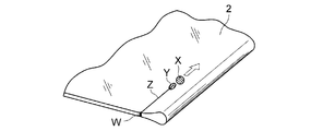
- the laser cleaving forms an initial crack (W) at the downstream end of the glass film (2), and the heating point (X) by laser irradiation in the longitudinal direction of the glass film (2).
- the heated portion is cooled while scanning the cooling point (Y) by the refrigerant, and the initial crack (W) is developed by the thermal stress generated at that time to form the breaking line (Z) It is.
- this breaking line (Z) is continuously formed over the back surface from the surface of a glass film (2). Accordingly, when the initial crack (W) is advanced to form the breaking line (Z), the ear corresponding to the part where the breaking line (Z) is formed is cut.
- the scanning of the laser heating point (X) and the cooling point (Y) by the coolant is performed in the direction in which the glass film (2) is transported with the laser heating point (X) and the cooling point (Y) by the coolant fixed. This is performed by sequentially transporting downstream (leftward in the example shown in FIG. 1).
- the glass film (2) excluding these both ends in the width direction is around the winding core (51) of the winding device (5).
- a protective sheet supply device (7) is disposed in the vicinity of the winding device (5), and the protective sheet (3) supplied from the protective sheet supply device (7). Is wound together with the glass film (2) in a roll around the winding core (51) of the winding device (5).
- the protective sheet supply device (7) is provided with a tension applying roller (71), and the protective sheet (3) is given a greater tension in the winding direction than the glass film (2).
- the glass roll (1) is produced by winding in the state made.
- the glass roll (1) may be created by winding the sheet (3) in a state in which a greater tension in the winding direction than the glass film (2) is applied to the protective sheet (3).
- a relatively large winding direction tension is applied to the protective sheet (3) without applying a large winding direction tension to the glass film (2), and the glass roll has no looseness in winding. (1) can be produced.
- the glass film ribbon (G) can be molded stably, and the glass film (2) having no warpage, undulation or change in plate thickness can be wound.
- the tension applied to the protective sheet (3) is preferably 0.01 to 10 GPa. If it is less than 0.01 GPa, the repulsive force of the glass film (2) may become stronger, making it difficult to produce a loose glass roll (1). If it exceeds 10 GPa, depending on the material, a protective sheet (3 ) May break.
- the tension applied to the protective sheet (3) is more preferably 0.05 to 5 GPa, and most preferably 0.1 to 2.5 GPa.
- the glass film (2) preferably has a low applied tension, and is preferably substantially free of tension.
- the molding accuracy of the glass film ribbon (G) can be increased by keeping the tension applied to the glass film (2) low.
- the glass film (2) is cut in the width direction by a width direction cutting device (not shown).
- the width direction cutting device may be located on the downstream side of the drawing path of the glass film ribbon (G) from the longitudinal direction cutting device (6), and conversely, the longitudinal direction cutting device. (6) may be located downstream of the width direction cutting device.
- the glass film (2) is preferably formed by an overflow down draw method.
- the overflow down draw method is a molding method in which both sides of the glass plate do not come into contact with the molded member during molding, and both surfaces (translucent surface) of the obtained glass plate are hard to be scratched and have a high surface without being polished. This is because quality can be obtained.
- the glass roll (1) which concerns on this invention is a glass roll which piled up the glass film (2) shape
- the silicate glass is used for the glass film (2), preferably silica glass or borosilicate glass is used, and most preferably non-alkali glass is used.
- an alkali component is contained in the glass film (2), cation is dropped on the surface, so-called soda blowing phenomenon occurs, and the structure becomes rough.
- the glass film (2) is curved and used, there is a possibility that the glass film (2) is likely to be damaged from a portion roughened due to aging.
- the alkali-free glass is a glass that does not substantially contain an alkali metal oxide, and specifically, a glass having an alkali metal oxide of 1000 ppm or less.
- the content of the alkali component in the present invention is preferably 500 ppm or less for alkali metal oxides, and more preferably 300 ppm or less for alkali metal oxides.
- OA-10G manufactured by Nippon Electric Glass Co., Ltd. is preferable.
- the glass film (2) can be wound up, it is particularly suitable for long objects. That is, the length (long side) with respect to the width (short side) of the glass film (2) is preferably 3 times or more, more preferably 5 times or more, and even more preferably 10 times or more. Thus, even if it is a long object, it can be packed compactly and is suitable for transportation.
- the width of the glass film (2) is 12.5 mm or more and is appropriately selected depending on the size of the substrate of the device used, such as a small display for a mobile phone to a large screen display, but is 100 mm or more. Preferably, it is 300 mm or more, more preferably 500 mm or more.
- the thickness of the glass film (2) is more preferably 1 ⁇ m to 200 ⁇ m, and most preferably 10 ⁇ m to 100 ⁇ m.
- appropriate flexibility can be provided to a glass film (2), and when a glass film (2) is wound up, it starts to a glass film (2). This is because unreasonable stress can be reduced and the glass film (2) can be prevented from being damaged.
- the thickness is less than 1 ⁇ m, the strength of the glass film (2) is insufficient, and if it exceeds 200 ⁇ m, the glass film (2) is likely to be damaged by a tensile stress when wound to a small diameter. Absent.
- the arithmetic average roughness Ra of both end surfaces in the width direction of the glass film (2) is preferably 0.1 ⁇ m or less, and more preferably 0.05 ⁇ m or less. This is because appropriate smoothness can be imparted to both end surfaces in the width direction of the glass film (2). Therefore, in this case, when the glass film (2) is wound into a roll shape, it is difficult for fine scratches to occur on both end faces of the glass film (2), and the glass film (2) can be wound without any trouble. It becomes possible. Moreover, since the glass powder generate
- the thickness of the protective sheet (3) is preferably 10 ⁇ m to 2000 ⁇ m. If it is less than 10 ⁇ m, the cushioning performance of the protective sheet is not sufficient, and if it exceeds 2000 ⁇ m, the roll outer diameter of the glass roll formed after winding the glass film (2) becomes unreasonably large. Is also not preferred.
- the protective sheet (3) should not be denatured such as softening around 100 ° C. Is preferred.
- the protective sheet (3) is preferably wider than the glass film (2) in the width direction. That is, it is preferable that the protective sheet (3) protrudes from both sides in the width direction of the glass film (2) in the state of the glass roll (1). If it does in this way, since the width direction both end surfaces of a glass film (2) are protected by a protection sheet (3), the fine damage
- protective sheet (3) ionomer film, polyethylene film, polypropylene film, polyvinyl chloride film, polyvinylidene chloride film, polyvinyl alcohol film, polypropylene film, polyester film, polycarbonate film, polystyrene film, polyacrylonitrile film, ethylene vinyl acetate
- copolymer film ethylene-vinyl alcohol copolymer film, ethylene-methacrylic acid copolymer film, polyamide resin film (nylon film), polyimide resin film, resin cushioning material such as cellophane, interleaf, nonwoven fabric, etc.
- a polyethylene foam resin sheet as the protective sheet (3) because it can absorb impact and has high strength against tensile stress.
- the protective sheet (3) is preferably made of an elastically deformable material. Thereby, the glass roll (1) without a looseness can be produced, giving the tension
- the tensile modulus of the protective sheet (3) is preferably 1 to 5 GPa.
- the protective sheet (3) is preferably provided with conductivity. If it does in this way, when taking out a glass film (2) from a glass roll (1), since it becomes difficult to produce peeling electrification between a glass film (2) and a protection sheet (3), glass film (2) and This is because the protective sheet (3) can be easily peeled off.
- the protective sheet (3) is made of a resin
- conductivity can be imparted by adding a component imparting electrical conductivity such as polyethylene glycol to the protective sheet (3).
- conductivity can be imparted by incorporating conductive fibers.
- Conductivity can also be imparted by forming a conductive film such as ITO on the surface of the protective sheet (3).
- the present invention can be suitably used for glass substrates used in flat panel displays such as liquid crystal displays and organic EL displays, devices such as solar cells, and cover glasses for organic EL lighting.
Landscapes
- Chemical & Material Sciences (AREA)
- Engineering & Computer Science (AREA)
- Materials Engineering (AREA)
- Organic Chemistry (AREA)
- Re-Forming, After-Treatment, Cutting And Transporting Of Glass Products (AREA)
- Packaging Frangible Articles (AREA)
- Liquid Crystal (AREA)
- Packaging Of Machine Parts And Wound Products (AREA)
- Controlling Rewinding, Feeding, Winding, Or Abnormalities Of Webs (AREA)
Abstract
L'invention concerne un procédé de fabrication d'un rouleau de verre(1) de façon à ce que le rouleau de film de verre soit tendu et serré sans avoir d'incidence défavorable sur la formation du film de verre et sans provoquer de problèmes tels qu'une rupture. A cet effet, le procédé de l'invention comprend la formation d'un film de verre (2) par un processus d'étirage par le bas, et le film de verre formé (2) est enroulé en forme de rouleau tout en étant superposé sur une feuille protectrice (3). Le rouleau de verre (1) est obtenu en effectuant l'enroulement d'une manière telle qu'une tension plus grande dans une direction d'enroulement soit appliquée à la feuille protectrice (3) qu'au film de verre (2).
Priority Applications (1)
| Application Number | Priority Date | Filing Date | Title |
|---|---|---|---|
| KR1020127013831A KR101833811B1 (ko) | 2010-03-03 | 2011-03-02 | 유리 롤 및 유리 롤의 제조 방법 |
Applications Claiming Priority (2)
| Application Number | Priority Date | Filing Date | Title |
|---|---|---|---|
| JP2010-046111 | 2010-03-03 | ||
| JP2010046111 | 2010-03-03 |
Publications (1)
| Publication Number | Publication Date |
|---|---|
| WO2011108564A1 true WO2011108564A1 (fr) | 2011-09-09 |
Family
ID=44531603
Family Applications (1)
| Application Number | Title | Priority Date | Filing Date |
|---|---|---|---|
| PCT/JP2011/054701 Ceased WO2011108564A1 (fr) | 2010-03-03 | 2011-03-02 | Rouleau de verre et procédé de fabrication de rouleau de verre |
Country Status (5)
| Country | Link |
|---|---|
| US (1) | US20110217521A1 (fr) |
| JP (1) | JP5720885B2 (fr) |
| KR (1) | KR101833811B1 (fr) |
| TW (1) | TWI530462B (fr) |
| WO (1) | WO2011108564A1 (fr) |
Cited By (2)
| Publication number | Priority date | Publication date | Assignee | Title |
|---|---|---|---|---|
| WO2013002210A1 (fr) * | 2011-06-30 | 2013-01-03 | 日本電気硝子株式会社 | Procédé de fabrication de rouleau de verre |
| US20250011216A1 (en) * | 2021-11-23 | 2025-01-09 | Corning Incorporated | Systems and methods for glass streak improvement via high resolution heating |
Families Citing this family (29)
| Publication number | Priority date | Publication date | Assignee | Title |
|---|---|---|---|---|
| JP5788134B2 (ja) * | 2008-10-01 | 2015-09-30 | 日本電気硝子株式会社 | ガラスロール及びガラスロールの製造方法 |
| JP5532507B2 (ja) * | 2008-10-01 | 2014-06-25 | 日本電気硝子株式会社 | ガラスロール及びガラスロールの処理方法 |
| US8113015B2 (en) * | 2009-06-17 | 2012-02-14 | Corning Incorporated | Control of the bow of a glass ribbon |
| US9656901B2 (en) | 2010-03-03 | 2017-05-23 | Nippon Electric Glass Co., Ltd. | Method of manufacturing a glass roll |
| TWI591029B (zh) | 2010-05-28 | 2017-07-11 | 康寧公司 | 纏繞玻璃帶的方法 |
| JP5669001B2 (ja) * | 2010-07-22 | 2015-02-12 | 日本電気硝子株式会社 | ガラスフィルムの割断方法、ガラスロールの製造方法、及びガラスフィルムの割断装置 |
| JP2013535499A (ja) | 2010-08-09 | 2013-09-12 | インスティテュート テクノロヒコ イ デ エステューディオス スペリオレス デ モンテレイ | 生物活性化合物が濃縮されたアボカド抽出物由来の抗菌、抗細菌、または芽胞発芽阻止活性 |
| TWI542527B (zh) * | 2010-11-30 | 2016-07-21 | 康寧公司 | 藉由張緊交插材料捲繞玻璃帶 |
| JP5679324B2 (ja) * | 2011-05-19 | 2015-03-04 | 日本電気硝子株式会社 | ガラスロールの製造方法および製造装置 |
| DE102011084132A1 (de) * | 2011-10-07 | 2013-04-11 | Schott Ag | Glasrolle |
| DE102011084129A1 (de) * | 2011-10-07 | 2013-04-11 | Schott Ag | Glasfolie mit speziell ausgebildeter Kante |
| JP6016723B2 (ja) * | 2012-08-07 | 2016-10-26 | 株式会社神戸製鋼所 | ガラスフィルム搬送装置 |
| JP5859405B2 (ja) | 2012-08-27 | 2016-02-10 | 株式会社神戸製鋼所 | ガラスフィルム搬送装置 |
| US9038414B2 (en) * | 2012-09-26 | 2015-05-26 | Corning Incorporated | Methods and apparatuses for steering flexible glass webs |
| US8904822B2 (en) * | 2012-11-06 | 2014-12-09 | Corning Incorporated | Thickness control of substrates |
| US9216924B2 (en) * | 2012-11-09 | 2015-12-22 | Corning Incorporated | Methods of processing a glass ribbon |
| KR20150084758A (ko) | 2012-11-13 | 2015-07-22 | 니폰 덴키 가라스 가부시키가이샤 | 판 유리의 제조 방법 및 제조 장치 |
| US9290403B2 (en) * | 2013-02-25 | 2016-03-22 | Corning Incorporated | Repositionable heater assemblies for glass production lines and methods of managing temperature of glass in production lines |
| DE102013110803A1 (de) * | 2013-09-30 | 2015-04-02 | Schott Ag | Verfahren zur Weiterverarbeitung von Dünnglas und verfahrensgemäß hergestelltes Dünnglas |
| DE102014207792A1 (de) * | 2014-04-25 | 2015-10-29 | Tesa Se | Dünnglasverbund und Verfahren zum Lagern einer Dünnglasfolie |
| DE102014106817A1 (de) * | 2014-05-14 | 2015-11-19 | Schott Ag | Verfahren und Vorrichtung zur Herstellung eines Dünnglas-Bands und verfahrensgemäß hergestelltes Dünnglas-Band |
| DE102016218176B4 (de) | 2015-10-02 | 2025-01-09 | Schott Ag | Langzeitbiegbares Glasmaterial, sowie Verfahren zur Herstellung eines langzeitbiegbaren Glasmaterials |
| KR102410719B1 (ko) * | 2017-02-07 | 2022-06-20 | 니폰 덴키 가라스 가부시키가이샤 | 유리 필름의 제조 방법 |
| JP6720900B2 (ja) * | 2017-03-14 | 2020-07-08 | 日本電気硝子株式会社 | ガラスロールの製造方法 |
| JP6818256B2 (ja) * | 2017-04-28 | 2021-01-20 | 日本電気硝子株式会社 | ガラスロールの製造方法 |
| JP6909403B2 (ja) * | 2017-07-31 | 2021-07-28 | 日本電気硝子株式会社 | ガラスフィルムの製造方法 |
| JP6999899B2 (ja) * | 2017-11-24 | 2022-01-19 | 日本電気硝子株式会社 | 透明導電膜付きガラスロール及び透明導電膜付きガラスシートの製造方法 |
| JP7262703B2 (ja) * | 2019-06-11 | 2023-04-24 | 日本電気硝子株式会社 | ガラスロールの製造方法 |
| JP7357500B2 (ja) * | 2019-09-26 | 2023-10-06 | 日東電工株式会社 | 複層構造体 |
Citations (3)
| Publication number | Priority date | Publication date | Assignee | Title |
|---|---|---|---|---|
| JP2001097733A (ja) * | 1999-09-29 | 2001-04-10 | Mitsubishi Plastics Ind Ltd | ガラスフィルムの取扱い方法及びガラス積層体 |
| JP2007314414A (ja) * | 2006-05-23 | 2007-12-06 | Jenoptik Automatisierungstechnik Gmbh | フロートガラスリボンの端部を切り落とす方法及び装置 |
| JP2008105882A (ja) * | 2006-10-24 | 2008-05-08 | Nippon Electric Glass Co Ltd | ガラスリボンの製造装置及びその製造方法 |
Family Cites Families (4)
| Publication number | Priority date | Publication date | Assignee | Title |
|---|---|---|---|---|
| DE19918936A1 (de) * | 1999-04-27 | 2000-11-02 | Schott Glas | Verfahren und Vorrichtung zur Herstellung von Einzelglasscheiben |
| DE10040640C2 (de) | 2000-08-16 | 2002-11-21 | Schott Glas | Verfahren und Vorrichtung zur Herstellung von Einzelglasscheiben |
| US20090314032A1 (en) * | 2006-10-24 | 2009-12-24 | Nippon Electric Glass Co., Ltd | Glass ribbon producing apparatus and process for producing the same |
| EP2236281B1 (fr) * | 2008-01-25 | 2012-08-15 | Asahi Glass Company, Limited | Procédé de fabrication d'un composite verre/résine |
-
2011
- 2011-03-01 JP JP2011044137A patent/JP5720885B2/ja active Active
- 2011-03-02 KR KR1020127013831A patent/KR101833811B1/ko active Active
- 2011-03-02 WO PCT/JP2011/054701 patent/WO2011108564A1/fr not_active Ceased
- 2011-03-02 US US13/038,747 patent/US20110217521A1/en not_active Abandoned
- 2011-03-03 TW TW100107132A patent/TWI530462B/zh active
Patent Citations (3)
| Publication number | Priority date | Publication date | Assignee | Title |
|---|---|---|---|---|
| JP2001097733A (ja) * | 1999-09-29 | 2001-04-10 | Mitsubishi Plastics Ind Ltd | ガラスフィルムの取扱い方法及びガラス積層体 |
| JP2007314414A (ja) * | 2006-05-23 | 2007-12-06 | Jenoptik Automatisierungstechnik Gmbh | フロートガラスリボンの端部を切り落とす方法及び装置 |
| JP2008105882A (ja) * | 2006-10-24 | 2008-05-08 | Nippon Electric Glass Co Ltd | ガラスリボンの製造装置及びその製造方法 |
Cited By (2)
| Publication number | Priority date | Publication date | Assignee | Title |
|---|---|---|---|---|
| WO2013002210A1 (fr) * | 2011-06-30 | 2013-01-03 | 日本電気硝子株式会社 | Procédé de fabrication de rouleau de verre |
| US20250011216A1 (en) * | 2021-11-23 | 2025-01-09 | Corning Incorporated | Systems and methods for glass streak improvement via high resolution heating |
Also Published As
| Publication number | Publication date |
|---|---|
| TW201136845A (en) | 2011-11-01 |
| JP5720885B2 (ja) | 2015-05-20 |
| KR101833811B1 (ko) | 2018-03-02 |
| US20110217521A1 (en) | 2011-09-08 |
| TWI530462B (zh) | 2016-04-21 |
| KR20130036172A (ko) | 2013-04-11 |
| JP2011201765A (ja) | 2011-10-13 |
Similar Documents
| Publication | Publication Date | Title |
|---|---|---|
| JP5720885B2 (ja) | ガラスロール、及びガラスロールの製造方法 | |
| JP5742082B2 (ja) | ガラスロールの製造方法 | |
| US10189736B2 (en) | Method of manufacturing a glass roll | |
| CN102083713B (zh) | 玻璃辊 | |
| JP5435267B2 (ja) | ガラスロール、ガラスロールの製造装置、及びガラスロールの製造方法 | |
| US11999133B2 (en) | Manufacturing method for glass film with resin tape, and manufacturing method for glass film | |
| JP5691148B2 (ja) | ガラスロール、ガラスロールの製造装置、及びガラスロールの製造方法 | |
| JP5783443B2 (ja) | ガラスロール及びガラスロールの製造方法 | |
| JP2011207721A (ja) | ガラスフィルムの切断方法及びガラスロールの製造方法 | |
| JP2015096313A (ja) | ガラスフィルム積層体および液晶パネルの製造方法 | |
| JP6327580B2 (ja) | ガラスフィルム積層体および電子デバイスの製造方法 | |
| WO2014178405A1 (fr) | Stratifié de film de verre, et procédé de production de dispositif électronique | |
| JP2016060135A (ja) | ガラスフィルム積層体、及び、電子デバイスの製造方法 |
Legal Events
| Date | Code | Title | Description |
|---|---|---|---|
| 121 | Ep: the epo has been informed by wipo that ep was designated in this application |
Ref document number: 11750673 Country of ref document: EP Kind code of ref document: A1 |
|
| ENP | Entry into the national phase |
Ref document number: 20127013831 Country of ref document: KR Kind code of ref document: A |
|
| NENP | Non-entry into the national phase |
Ref country code: DE |
|
| 122 | Ep: pct application non-entry in european phase |
Ref document number: 11750673 Country of ref document: EP Kind code of ref document: A1 |