WO2011108482A1 - 賦型シート及びその製造方法 - Google Patents
賦型シート及びその製造方法 Download PDFInfo
- Publication number
- WO2011108482A1 WO2011108482A1 PCT/JP2011/054478 JP2011054478W WO2011108482A1 WO 2011108482 A1 WO2011108482 A1 WO 2011108482A1 JP 2011054478 W JP2011054478 W JP 2011054478W WO 2011108482 A1 WO2011108482 A1 WO 2011108482A1
- Authority
- WO
- WIPO (PCT)
- Prior art keywords
- sheet
- ink
- infrared
- resin sheet
- resin
- Prior art date
- Legal status (The legal status is an assumption and is not a legal conclusion. Google has not performed a legal analysis and makes no representation as to the accuracy of the status listed.)
- Ceased
Links
Images










Classifications
-
- B—PERFORMING OPERATIONS; TRANSPORTING
- B29—WORKING OF PLASTICS; WORKING OF SUBSTANCES IN A PLASTIC STATE IN GENERAL
- B29C—SHAPING OR JOINING OF PLASTICS; SHAPING OF MATERIAL IN A PLASTIC STATE, NOT OTHERWISE PROVIDED FOR; AFTER-TREATMENT OF THE SHAPED PRODUCTS, e.g. REPAIRING
- B29C45/00—Injection moulding, i.e. forcing the required volume of moulding material through a nozzle into a closed mould; Apparatus therefor
- B29C45/16—Making multilayered or multicoloured articles
-
- B—PERFORMING OPERATIONS; TRANSPORTING
- B29—WORKING OF PLASTICS; WORKING OF SUBSTANCES IN A PLASTIC STATE IN GENERAL
- B29C—SHAPING OR JOINING OF PLASTICS; SHAPING OF MATERIAL IN A PLASTIC STATE, NOT OTHERWISE PROVIDED FOR; AFTER-TREATMENT OF THE SHAPED PRODUCTS, e.g. REPAIRING
- B29C45/00—Injection moulding, i.e. forcing the required volume of moulding material through a nozzle into a closed mould; Apparatus therefor
- B29C45/14—Injection moulding, i.e. forcing the required volume of moulding material through a nozzle into a closed mould; Apparatus therefor incorporating preformed parts or layers, e.g. injection moulding around inserts or for coating articles
- B29C45/14827—Injection moulding, i.e. forcing the required volume of moulding material through a nozzle into a closed mould; Apparatus therefor incorporating preformed parts or layers, e.g. injection moulding around inserts or for coating articles using a transfer foil detachable from the insert
-
- B—PERFORMING OPERATIONS; TRANSPORTING
- B29—WORKING OF PLASTICS; WORKING OF SUBSTANCES IN A PLASTIC STATE IN GENERAL
- B29C—SHAPING OR JOINING OF PLASTICS; SHAPING OF MATERIAL IN A PLASTIC STATE, NOT OTHERWISE PROVIDED FOR; AFTER-TREATMENT OF THE SHAPED PRODUCTS, e.g. REPAIRING
- B29C45/00—Injection moulding, i.e. forcing the required volume of moulding material through a nozzle into a closed mould; Apparatus therefor
- B29C45/17—Component parts, details or accessories; Auxiliary operations
- B29C45/26—Moulds
-
- B—PERFORMING OPERATIONS; TRANSPORTING
- B29—WORKING OF PLASTICS; WORKING OF SUBSTANCES IN A PLASTIC STATE IN GENERAL
- B29C—SHAPING OR JOINING OF PLASTICS; SHAPING OF MATERIAL IN A PLASTIC STATE, NOT OTHERWISE PROVIDED FOR; AFTER-TREATMENT OF THE SHAPED PRODUCTS, e.g. REPAIRING
- B29C59/00—Surface shaping of articles, e.g. embossing; Apparatus therefor
- B29C59/16—Surface shaping of articles, e.g. embossing; Apparatus therefor by wave energy or particle radiation, e.g. infrared heating
-
- B—PERFORMING OPERATIONS; TRANSPORTING
- B29—WORKING OF PLASTICS; WORKING OF SUBSTANCES IN A PLASTIC STATE IN GENERAL
- B29C—SHAPING OR JOINING OF PLASTICS; SHAPING OF MATERIAL IN A PLASTIC STATE, NOT OTHERWISE PROVIDED FOR; AFTER-TREATMENT OF THE SHAPED PRODUCTS, e.g. REPAIRING
- B29C59/00—Surface shaping of articles, e.g. embossing; Apparatus therefor
- B29C59/18—Surface shaping of articles, e.g. embossing; Apparatus therefor by liberation of internal stresses, e.g. plastic memory
-
- B—PERFORMING OPERATIONS; TRANSPORTING
- B29—WORKING OF PLASTICS; WORKING OF SUBSTANCES IN A PLASTIC STATE IN GENERAL
- B29C—SHAPING OR JOINING OF PLASTICS; SHAPING OF MATERIAL IN A PLASTIC STATE, NOT OTHERWISE PROVIDED FOR; AFTER-TREATMENT OF THE SHAPED PRODUCTS, e.g. REPAIRING
- B29C61/00—Shaping by liberation of internal stresses; Making preforms having internal stresses; Apparatus therefor
- B29C61/02—Thermal shrinking
-
- B—PERFORMING OPERATIONS; TRANSPORTING
- B29—WORKING OF PLASTICS; WORKING OF SUBSTANCES IN A PLASTIC STATE IN GENERAL
- B29C—SHAPING OR JOINING OF PLASTICS; SHAPING OF MATERIAL IN A PLASTIC STATE, NOT OTHERWISE PROVIDED FOR; AFTER-TREATMENT OF THE SHAPED PRODUCTS, e.g. REPAIRING
- B29C61/00—Shaping by liberation of internal stresses; Making preforms having internal stresses; Apparatus therefor
- B29C61/06—Making preforms having internal stresses, e.g. plastic memory
-
- B—PERFORMING OPERATIONS; TRANSPORTING
- B29—WORKING OF PLASTICS; WORKING OF SUBSTANCES IN A PLASTIC STATE IN GENERAL
- B29C—SHAPING OR JOINING OF PLASTICS; SHAPING OF MATERIAL IN A PLASTIC STATE, NOT OTHERWISE PROVIDED FOR; AFTER-TREATMENT OF THE SHAPED PRODUCTS, e.g. REPAIRING
- B29C35/00—Heating, cooling or curing, e.g. crosslinking or vulcanising; Apparatus therefor
- B29C35/02—Heating or curing, e.g. crosslinking or vulcanizing during moulding, e.g. in a mould
- B29C35/08—Heating or curing, e.g. crosslinking or vulcanizing during moulding, e.g. in a mould by wave energy or particle radiation
- B29C35/0805—Heating or curing, e.g. crosslinking or vulcanizing during moulding, e.g. in a mould by wave energy or particle radiation using electromagnetic radiation
- B29C2035/0822—Heating or curing, e.g. crosslinking or vulcanizing during moulding, e.g. in a mould by wave energy or particle radiation using electromagnetic radiation using IR radiation
-
- Y—GENERAL TAGGING OF NEW TECHNOLOGICAL DEVELOPMENTS; GENERAL TAGGING OF CROSS-SECTIONAL TECHNOLOGIES SPANNING OVER SEVERAL SECTIONS OF THE IPC; TECHNICAL SUBJECTS COVERED BY FORMER USPC CROSS-REFERENCE ART COLLECTIONS [XRACs] AND DIGESTS
- Y10—TECHNICAL SUBJECTS COVERED BY FORMER USPC
- Y10T—TECHNICAL SUBJECTS COVERED BY FORMER US CLASSIFICATION
- Y10T428/00—Stock material or miscellaneous articles
- Y10T428/24—Structurally defined web or sheet [e.g., overall dimension, etc.]
- Y10T428/24479—Structurally defined web or sheet [e.g., overall dimension, etc.] including variation in thickness
Definitions
- the present invention relates to a molding sheet capable of forming irregularities on the surface of an injection-molded body by peeling after injection molding in a state of being inserted into an injection mold, and a method for producing the same.
- the concavo-convex forming layer has fine concavo-convex, and is made of urethane acrylate, polyester acrylate, epoxy acrylate, polyether acrylate.
- a molding film which is a cured product of a photocurable resin composition containing the selected acrylate oligomer and a release agent as essential components, is inserted into an injection mold and the resin is injected into the injection mold.
- the moldable film is composed of a plurality of layers of a base material and a concavo-convex forming layer, and there is a problem that the concavo-convex forming layer is peeled off from the base material at the time of injection molding or peeling and cannot be completely peeled off. . Also, in order to use the stamper plate, it was necessary to remake the plate according to the uneven pattern.
- the problem to be solved by the present invention is that in the method of manufacturing an injection-molded article having irregularities on the surface, it is excellent in handling without embossing, can accurately reproduce complex irregularities, and can be sufficiently felt by visual and tactile sensations.
- An object of the present invention is to provide a moldable sheet for obtaining a reproducible injection-molded article having excellent design characteristics having unevenness with different heights.
- the inventors use a shaped sheet having a partial film thickness difference formed by irradiating a resin sheet having heat shrinkability having a part A and a part B having different infrared absorptivity formed on the surface by infrared irradiation. This solved the above problem.
- part B are the said site
- the heat-shrinkable resin sheet shrinks by heating to restore the sheet to the state before stretching.
- the force indicated at this time is the orientation return strength, and the strength varies depending on the heating temperature.
- the inventors of the present invention hold the heat-shrinkable resin sheet so that the plurality of portions in the same plane of the resin sheet have different surface temperatures, and at least the plurality of portions. It has been found that when one surface temperature is heated to a surface temperature equal to or higher than the orientation return strength inflection point temperature T of the resin sheet, the sheet behavior of a plurality of portions is different, resulting in a difference in film thickness at each portion. .
- the present invention succeeded in intentionally producing a film thickness difference, that is, unevenness by utilizing the temperature difference of the sheet.
- Irradiation with infrared rays so that a plurality of parts on the same plane of the resin sheet have different surface temperatures means that a part having a relatively high surface temperature is part A and a part having a relatively low surface temperature Specifically, there is a method using infrared absorbing ink or infrared reflecting ink (described later (1) to (3)).
- Infrared absorbing ink or infrared reflecting ink is ink that reacts to infrared rays.
- Infrared absorbing ink is an ink containing an infrared absorbing agent and the like, and absorbs infrared rays and generates heat. That is, when the resin sheet printed with the infrared absorbing ink is irradiated with infrared rays, only the amount of heat applied by the infrared irradiation is applied only to the portion printed with the infrared absorbing ink.
- the infrared reflecting ink is an ink containing an infrared reflecting material and reflects the irradiated infrared rays.
- the resin sheet printed with infrared reflecting ink is irradiated with infrared rays from the resin sheet side (that is, the surface opposite to the printing surface of the resin sheet), the infrared rays that have passed through the resin sheet are reflected by the infrared reflecting ink.
- the printing part where the infrared transmission part and the reflection part overlap is applied with a heat amount equal to or more than the amount of heat applied by infrared irradiation (specifically, the part A is compared with the part B where no pattern is provided) It is estimated that heat can be supplied to the sheet more efficiently).
- the surface temperature of the portion can be increased, and as a result, the infrared absorption of the resin sheet is increased.
- a temperature difference can be generated between a portion printed with ink and a portion not printed.
- the resin sheet having heat shrinkability is provided with a pattern with infrared absorbing ink or infrared reflecting ink, and the pattern A and the pattern A are provided with the infrared absorbing ink or infrared reflecting ink. Irradiation with infrared rays is performed so that the surface temperature is different from that of the non-part B. Since only the part A has a heat amount equal to or greater than the amount of heat applied by infrared irradiation, the surface temperature of the part A becomes higher than the part B that is not printed.
- the resin sheet having heat shrinkability is provided with a pattern so as to have the portion A having a high ink concentration and the portion B having a low ink concentration with infrared absorbing ink or infrared reflecting ink, Irradiation with infrared rays is performed so that the portion A having a high ink density and the portion B having a low ink density have different surface temperatures.
- both the part A and the part B are subjected to heat more than the amount of heat applied by infrared irradiation, but the part A is heated more as a result of the higher ink density than the part B. Therefore, the surface temperature of the part A is relatively higher than that of the part B.
- a resin sheet having heat shrinkability is provided with a pattern with a plurality of infrared absorbing inks or infrared reflecting inks having different infrared absorptivity or reflectance
- the portion A where the pattern is provided with the ink having high infrared absorption or reflectance and the portion B where the pattern is provided with the ink having low infrared absorption or reflectance are set to have different surface temperatures.
- both the part A and the part B are subjected to heat more than the amount of heat imparted by infrared irradiation, but the part A is heated more as a result of providing ink having higher infrared absorption or reflectance than the part B. Therefore, the surface temperature of the part A is relatively higher than that of the part B.
- the present invention is a molding sheet that can impart irregularities to the surface of an injection-molded product by peeling after injection molding in the state of being inserted into an injection mold, and has an infrared absorbing property formed on the surface.
- the present invention is a method for producing the above-described shaping sheet, wherein the resin sheet having heat shrinkability having a part A and a part B having different infrared absorptivity formed on the surface is retained, The surface temperature of the part A and the part B is different between the part A and the part B, and at least the surface temperature of the part A is a surface temperature equal to or higher than the orientation return strength inflection point temperature T of the resin sheet.
- seat which makes infrared irradiation and produces the film thickness difference in the said site
- the moldable sheet of the present invention By using the moldable sheet of the present invention, it is excellent in handling, can accurately reproduce complex irregularities, and has excellent design with injections having irregularities with height differences that can be sufficiently felt by visual and tactile sensations.
- the body can be obtained with good reproducibility.
- the shaped sheet of the present invention has irregularities on both sides in the state where the preform is not performed, and irregularities are formed on one side in the state where the preform is performed, and in any state as a molding sheet for injection molding Can be used.
- the shaped sheet of the present invention has a concavo-convex shape in which the internal stress is relieved, so that the concavo-convex is relieved by heating or pressure by the preform or injection molding, and does not fall out. It is possible to accurately reproduce complex irregularities. Accordingly, the surface of the injection-molded product can be uneven by performing injection molding in the state of being inserted into the injection mold and then peeling off.
- the unevenness appears in the present invention in the infrared absorption. It is the site
- the ink can be printed with a general-purpose printing method such as gravure printing, screen printing, and ink jet printing, and does not require a physical method for imparting irregularities, so that defects such as winding misalignment and gauge bands are less likely to occur. The cost can be reduced without requiring an excessive device such as embossing in the sheet manufacturing process.
- the formation of the unevenness is that the adjacent portion A and the portion B in the same plane of the resin sheet have different surface temperatures while holding the resin sheet having heat shrinkability.
- Arise a part having a relatively high surface temperature is defined as part A, and a part having a relatively low surface temperature is defined as part B. At this time, the part A becomes a relatively concave part and the part B becomes a relatively convex part.
- the resin sheet having heat shrinkability is irradiated with infrared rays, the resin is plasticized and the orientation return of the resin sheet starts to be reduced, so that the thinning of the central portion occurs due to the self-shrinkage behavior.
- the thickness change due to this self-shrinkage behavior has no starting point and tends to shrink overall and thicken when the resin sheet is not held, but when the resin sheet is held by a clamp or the like, the temperature changes. There is a tendency for shrinkage to occur starting from a low clamp portion or the like. Therefore, the part A often becomes thinner than the film thickness of the resin sheet before infrared irradiation, that is, before shrinkage.
- the part B is a part adjacent to the part A and has a surface temperature different from the part A and a surface temperature relatively lower than that of the part A.
- the part B is thinned at the center of the part A. Therefore, it is considered that the resin component present in the part A is moved and contracted due to self-shrinkage, and the film thickness is relatively thicker than the part A.
- the part B is often thicker than the film thickness of the resin sheet before infrared irradiation, that is, before shrinkage.
- the boundary between the part A and the part B becomes thicker. Thereby, a stronger sense of unevenness can be obtained.
- FIGS. Figure 1 shows an infrared heater applied to a heat-shrinkable resin sheet printed with a pattern using three types of ink, high-concentration infrared absorption ink, low-concentration infrared absorption ink, and color ink (which does not absorb infrared rays). It is a figure which shows the one aspect which showed the state which uses and irradiates infrared rays, and FIG. 2 showed the state of the said resin sheet after irradiating infrared rays in the state which hold
- the printed portion 4 of the high-density infrared absorbing ink that is, the portion A is most thinned or becomes a concave portion, and the low-density infrared absorbing ink.
- 5 is a thicker film than the printing unit 4) but is a thin film than the color ink printing unit 6, and is a convex part when viewed from the printing unit 4. Furthermore, since the color ink printing part 6 becomes the thickest film, it becomes the highest convex part.
- the high-concentration infrared-absorbing ink printing part is a concave part
- the low-concentration infrared-absorbing ink printing part is a low convex part or non-printing part. Is the highest protrusion. (Not shown) As described above, since the film is relatively thin and thick, unevenness is generated.
- the formation of the unevenness occurs evenly on both surfaces of the resin sheet as shown in FIG. Accordingly, the surface of the resin sheet in contact with the adherend is also uneven.
- the height difference of the unevenness can be measured with a surface roughness meter or a film thickness meter. If the difference between the highest and lowest surface unevenness (hereinafter referred to as the film thickness difference) is about 10 ⁇ m, it can be recognized as unevenness expression. In order to express clear irregularities, the film thickness difference is preferably about 15 ⁇ m, and more preferably 20 ⁇ m or more. On the other hand, since the difference in film thickness becomes smaller in proportion to the expansion ratio, the deeper molded product tends to decrease in uneven film thickness. Moreover, the width of each unevenness tends to increase as the development magnification increases.
- the pattern expressed by the unevenness is not particularly limited, and there is no particular limitation on the thickness, size, shape, etc. of the drawing that expresses the pattern shape such as a pattern or a character. That is, according to the present invention, since the unevenness can be expressed by printing, handwriting or the like by the means (1) to (3), any unevenness can be used as long as it is a pattern or character that can cause a plate or can be printed. Examples of patterns include drawing expressed with pointillism and line drawing (specifically, outlines of paintings and characters, wood grain, stripes, hairline patterns, etc.), dots, geometric patterns, characters and marks themselves When it is desired, an object having a small pattern area is more preferable.
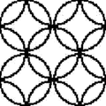
- FIG. 3 to FIG. 6 show examples of pattern patterns expressed by unevenness in the present invention.
- the black part is a part printed with an infrared absorbing ink or an infrared reflecting ink.
- 3 represents a stripe
- FIG. 4 represents a dot
- FIG. 5 represents a geometric pattern
- FIG. 6 represents a grain.
- “surface temperature of the part A and the part B” is defined as an index of the temperature.
- the thermal behavior of the part A and the part B of the resin sheet is the part A. It is presumed that it occurs in a state where the temperature is uniformly applied not only to the surface of the part B but also to the inside.
- the surface temperature was defined.
- the surface temperature used was "Thermo Tracer 9100" manufactured by NEC / Avio.
- the heat-shrinkable resin sheet used in the present invention (hereinafter abbreviated as “resin sheet S”) is a resin that exhibits spreadability by heating and can be formed into a film, and further has an orientation return strength inflection point. Furthermore, a thermoplastic resin sheet is preferable from the viewpoint of easy spreadability during vacuum forming.
- the orientation return strength inflection point temperature in the present invention is the film temperature when heat is applied to the film from the outside, and when the film itself reaches this temperature, the stretched molecules start to contract, In the present invention, the orientation return strength inflection point temperature T is defined by the following method.
- the orientation return strength used in the present invention is measured in accordance with ASTM D-1504.
- the orientation return strength is the force that the sheet shows when it is heated to restore its state before stretching, and the maximum stress at each measured temperature is divided by the cross-sectional area of the sheet. It becomes a parameter
- the temperature T of the inflection point that becomes the convex of the right-upward graph showing the relationship between the orientation return strength and the heating temperature was obtained using the heat shrinkage stress measurement method.
- the orientation return strength inflection point temperature T When there are a plurality of inflection points that are convex, the temperature of the inflection point in the highest temperature range is defined as the orientation return strength inflection point temperature T.
- FIG. 7 is a graph when measuring a biaxially stretched PET sheet “Soft Shine X1130 (film thickness 125 ⁇ m)” (sheet S1 in Examples) manufactured by Toyobo Co., Ltd.
- the inflection point temperature T188 ° C. which is convex in the highest temperature range of the graph was defined as the orientation return strength inflection point temperature T of the sheet S1.
- the resin sheet having an orientation return strength inflection point is generally subjected to stretching treatment, and as the stretching treatment method, the resin is melt-extruded by extrusion film forming method or the like to form a sheet, and then uniaxial stretching. It is common to perform simultaneous biaxial stretching or sequential biaxial stretching. In the case of sequential biaxial stretching, it is common to first perform longitudinal stretching and then perform lateral stretching. Specifically, a method of combining longitudinal stretching using a speed difference between rolls and transverse stretching using a tenter is often used.
- the tenter method is advantageous in that a wide range of products can be obtained and productivity is high.
- the stretching conditions, etc. depending on the resin plasticity and the desired physical properties and moldability, but the surface magnification is usually 1.2 to 18 times, more preferably 2.0 to 15 times.
- the draw ratio in the flow direction is 1.2 to 5 times, preferably 1.5 to 4.0 times
- the draw ratio in the cross direction with respect to the flow direction is preferably 1.1 to 5 times. Is 1.5 to 4.5 times.
- the draw ratio in each direction of simultaneous biaxial stretching is 1.1 to 3.5 times, preferably 1.2 to 4.2 times.
- a stretched sheet such as a uniaxially stretched sheet or a biaxially stretched sheet can be used, but a biaxially stretched sheet is preferable because it can maximize the effects of the present invention.
- a simultaneous biaxially stretched sheet if it is a simultaneous biaxially stretched sheet, the in-plane shrinkage rate is uniform, so an uneven design without distortion can be obtained.
- strain is calculated in advance and uniaxially stretched or two-stage sequential biaxially stretched sheet is used There is also.
- the resin used is not particularly limited as long as it is a stretchable resin.
- polyester resin such as polyethylene terephthalate and polybutylene terephthalate, polyolefin resin such as polyethylene and polypropylene, polyvinyl chloride, acrylic resin and polystyrene resin. Nylon or vinylon can be used. Of these, a polyester resin is preferred because of its good uniformity of thickness after stretching.
- the film thickness of the resin sheet S is not particularly limited as long as it is a film thickness usually used for a thermoforming sheet. In general, a sheet having a thickness of about 0.1 mm to 0.5 mm is preferably used.
- the infrared absorbing ink or infrared reflecting ink used in the means (1) to (3) will be described.
- the infrared absorbing ink is an ink containing an infrared absorbing agent
- the infrared reflecting ink is an ink containing an infrared reflecting substance, both of which are used as security inks.
- the infrared absorbing ink absorbs the irradiated infrared rays and generates heat.
- the infrared reflecting ink is an ink containing an infrared reflecting material and reflects the irradiated infrared rays.
- the temperature of the resin sheet S itself is increased by irradiating with infrared rays to obtain an elastic region suitable for thermoforming.
- the portion A at this time a portion having a relatively high surface temperature
- the temperature difference between the part A and the part B is preferably 7 ° C. or higher, more preferably 10 ° C. or higher, and further preferably 15 ° C. or higher because deeper irregularities can be imparted.
- Infrared irradiation may be performed so that only part A has a surface temperature equal to or higher than the orientation return strength inflection point temperature T, and both part A and part B have surface temperatures equal to or higher than the orientation return strength inflection point temperature T. You may irradiate with infrared rays. In this case, deeper irregularities can be obtained in the latter case.
- Infrared absorbing ink is a material that is generally commercially available as an infrared absorbing agent, or various known infrared absorbing pigments that have a function of generating heat by absorbing wavelengths in the wavelength range of red, near infrared, and infrared laser light.
- Ink containing dyes and dyes is preferred.
- Specific examples of the infrared absorber include insoluble azo pigments, azo lake pigments, condensed azo pigments, chelate azo pigments, phthalocyanine pigments, anthraquinone pigments, perylene and perinone pigments, thioindigo pigments, quinacridone pigments, dioxazine pigments.
- Infrared reflective materials contained in the infrared reflective ink include metals such as aluminum, gold, silver, copper, brass, titanium, chromium, nickel, nickel chrome, and stainless steel, Fe-Cr complex oxides, antimony trioxide, and antimony dichromate. Etc.
- the particle size of the infrared absorber or infrared reflecting material is not particularly limited, and can be used without any particular problem as long as it is a range used as a normal ink.
- the ink density increases, the amount of heat applied to the portion A increases. Therefore, it is preferable to change the content appropriately depending on the desired degree of unevenness.
- the concentration is too low, the amount of heat generated by infrared irradiation and the amount of infrared reflection are too small to form a recess, and if the concentration is too high, the amount of heat generated and the amount of infrared reflection are too large, causing tears and holes. Therefore, it is necessary to adjust appropriately so that the elastic modulus at the time of molding does not become 0.5 MPa or less as described later.
- the ink varnish is not particularly limited, and a known varnish resin or the like can be used.
- the varnish resin include acrylic resin, polyurethane resin, polyester resin, vinyl resin (vinyl chloride, vinyl acetate, vinyl chloride-vinyl acetate copolymer resin), chlorinated olefin resin, ethylene-acrylic resin, petroleum Well-known inks such as a resin-based resin and a cellulose derivative resin can be used.
- the method of providing a pattern on the resin sheet S with infrared absorbing ink or infrared reflecting ink includes handwriting, coating, printing, etc., but printing is preferred industrially.
- the method is not particularly limited, and examples thereof include gravure printing, offset printing, screen printing, ink jet printing, brush coating, roll coating, comma coating, rod gravure coating, and micro gravure coating. Of these, the gravure printing method is preferred.
- irradiation is performed so that infrared rays pass through the resin sheet and reach the infrared absorbing ink or infrared reflecting ink layer.
- the infrared reflection ink reflects the infrared rays before passing through the resin sheet, that is, the infrared rays are transmitted to the printing portion of the resin sheet. Without being plasticized.
- the portion A provided with a pattern with infrared absorbing ink or infrared reflecting ink has a surface temperature relatively high due to the application of heat equal to or greater than the amount of infrared irradiation, resulting in a recess.
- the surface temperature becomes relatively lower than the part A and becomes a convex part.
- the means of (2) heat is applied to the part A and the part B at an amount equal to or greater than the amount of infrared irradiation, but the part A is heated more than the part B as a result of the ink density higher than the part B. Therefore, the surface temperature of the part A is relatively higher than that of the part B, so that the part A becomes a concave part and the part B becomes a convex part.
- the means (2) is provided with the portion A and the portion B using inks having different ink concentrations, or the amount of ink is increased in the portion A although the ink is one kind. The ink density can be adjusted by this method. Further, it is not necessary that the portion A is one.
- the portion using the ink having the lowest density becomes the portion B and becomes a convex portion, and the ink having the highest concentration.
- the portion using the is the portion A ′′ which is the deepest recess.
- the part A is provided with ink having higher infrared absorption or reflectance than the part B. It adds more heat than it does. Therefore, the surface temperature of the part A is relatively higher than that of the part B, so that the part A becomes a concave part and the part B becomes a convex part.
- the absorptivity of the infrared absorbing ink or the reflectance of the infrared reflecting ink cannot be generally compared, but as a rough guide, when using an infrared reflecting ink using aluminum and an infrared absorbing ink using carbon black in combination
- the ink using aluminum becomes a concave portion
- the ink using carbon black becomes a convex portion.
- an infrared absorbing ink using carbon black and an infrared absorbing ink using titanium oxide are used in combination, the ink using carbon black becomes a concave portion, and the ink using titanium oxide becomes a convex portion.
- the part A when the part A is printed with ink containing aluminum and the part B is printed with ink containing carbon black, the part A becomes a concave part and the part B becomes a convex part. Further, if the part A is printed with an ink containing carbon black and the part B is printed with an ink containing titanium oxide, the part A becomes a concave part and the part B becomes a convex part.
- the heat generating material can be appropriately selected in consideration of a desired uneven design and a design having visibility.
- the portion of the multiple printing is deepest. It is a concave portion, and the portion of general printing is a convex portion when viewed from a plurality of portions to be printed, and a concave portion when viewed from a non-printing portion, and an unevenness such that the non-printing portion is a convex portion can be provided.
- the printed portion of the high concentration ink is the deepest concave portion, and the concentration
- the printing part using a low-density ink is a convex part when viewed from the printing part of the ink with the above high density, and is a concave part when viewed from a non-printing part, and the non-printing part is a convex part. Can do.
- the resin sheet S may be provided with a pattern layer that can be transferred to the injection molded body.
- the molding sheet in which the resin sheet S / the release layer / the infrared absorbing ink and the infrared reflecting ink that cause the unevenness are laminated in this order is injection molded in the state of being inserted into an injection mold and then peeled off. Then, in order to peel between the release layer and the infrared absorbing ink or the infrared reflecting ink, the infrared absorbing ink or the infrared reflecting ink is transferred to the injection-molded product, that is, an additive having a pattern along the unevenness.
- a decorated injection molded body can be obtained.
- a general-purpose color material can be utilized, which is preferable.
- a pattern layer may be separately provided with ink containing a general-purpose color material by changing the plate.
- the color material used in this case is not particularly limited, but it is preferable to change the blending ratio as appropriate according to the purpose because the heat-absorbing color material can cause unevenness in the printed portion.
- a pattern other than the pattern along the unevenness can be transferred.
- the surface protective layer When the pattern layer is transferred, it is transparent, translucent or clear in order to impart performance such as friction resistance, scratch resistance, weather resistance, stain resistance, water resistance, chemical resistance and heat resistance.
- One or more surface protective layers can be provided.
- the surface protective layer is preferably disposed between a later-described release layer and a pattern printing layer to be transferred. As a result, the printed layer is under the surface protective layer, and it is possible to protect the pattern of the obtained injection-molded product. Specifically, it is desirable to laminate in the order of resin sheet S / release layer / transparent cured resin layer / pattern printing layer to be transferred / adhesive layer.
- the surface protective layer may be a resin layer exhibiting plasticity at a temperature higher than that of the resin sheet S, but preferably has a flexibility capable of following the film thickness difference between the part A and the part B to some extent. From such a viewpoint, in addition to a methacrylic resin layer having a high glass transition temperature, a surface protective layer that is partially crosslinked to such an extent that the spreadability is not hindered is preferable.
- thermosetting reaction between isocyanate and hydroxyl group thermosetting reaction between epoxy group and hydroxyl group
- An existing reaction such as a hydrolytic condensation reaction of a functional silyl group may be used, but a thermosetting reaction between an isocyanate and a hydroxyl group is preferable because the crosslinking reaction can be promoted by using heat applied during thermoforming.
- the surface protective layer is preferably transparent, translucent, or colored clear so that the provided concavo-convex pattern (depth feeling) can be visually recognized.
- the release layer material is epoxy resin release agent, epoxy melamine resin release agent, amino alkyd resin release agent, melamine resin release agent, silicone resin release agent, fluororesin release agent Agents, cellulose derivative release agents, urea resin release agents, polyolefin resin release agents, paraffin release agents, and composite release agents thereof can be used.
- a matte feeling can be expressed by including fine powders such as calcium carbonate, silica, zinc oxide, magnesium carbonate, polyethylene wax, and glass beads in the release layer.
- fine powders such as calcium carbonate, silica, zinc oxide, magnesium carbonate, polyethylene wax, and glass beads in the release layer.
- various printing methods and coating methods are preferably used.
- an adhesive layer or a pressure-sensitive adhesive layer that is usually used for the thermal transfer sheet may be provided.
- the adhesive layer is arbitrarily used for the purpose of favorably adhering the ink to the resin for injection molding, and therefore needs to be selected according to the type of the resin for injection molding, but as a general adhesive, for example, an acrylic resin, Synthesis of urethane resin, urethane modified polyester resin, polyester resin, epoxy resin, ethylene-vinyl acetate copolymer resin (EVA), vinyl chloride resin, vinyl chloride-vinyl acetate copolymer resin, natural rubber, SBR, NBR, silicone rubber, etc. Examples thereof include rubber, and a solvent type or solventless type can be used.
- the shaping sheet of the present invention is in a state before a partial film thickness difference occurs, and the film thickness as a whole with the addition of the infrared absorbing ink or infrared reflecting ink layer or other layers is the thermoforming sheet.
- the film thickness is not particularly limited as long as it is usually used, but it is particularly preferable that the film thickness is used for vacuum forming for the reasons described below.
- the shaping sheet of the present invention holds the resin sheet S having the portions A and B having different infrared absorptivity formed on the surface subjected to the means (1) to (3).
- the part A and the part B have different surface temperatures of the part A and the part B, and at least the surface temperature of the part A is not less than the orientation return strength inflection point temperature T of the resin sheet.
- the surface temperature is obtained by irradiating with infrared rays so as to cause a difference in film thickness between the part A and the part B.
- the held state is a state in which only a part of the outer periphery of the resin sheet S or the entire outer periphery is fixed as described above, that is, the surface of the sheet S in contact with the resin for injection molding is a substrate or the like. Refers to an unsupported state.
- a method of fixing a part of the resin sheet S by clamping or the like there are a method of fixing a part of the resin sheet S by clamping or the like, and a method of clamping and fixing the entire periphery of the resin sheet S by a frame-shaped clamp.
- a method in which the entire periphery of the sheet is clamped and fixed by a frame-like clamp is preferable.
- fixation here is possible also by preventing plasticization and shrinkage
- Tg glass transition temperature
- infrared irradiation is performed so that at least the surface temperature of the portion A is equal to or higher than the orientation return strength inflection point temperature T of the resin sheet. Is heated to a different surface temperature, and as a result, a difference in film thickness occurs between the part A and the part B.
- the infrared rays irradiated at this time are not particularly limited as long as they are in the wavelength range from red to near infrared and infrared laser light.
- the upper limit of the amount of infrared irradiation is not particularly limited.
- the resin sheet S may be deteriorated in rigidity, which may cause plasticization and breakage.
- Is preferably set to 0.5 MPa or more, more preferably 1 MPa or more as a value of storage elastic modulus (E ′) of dynamic viscoelasticity measurement obtained by JIS K7244-1 method. It is preferable to set the dose so that As an infrared irradiation device, anything such as an oven or a heater may be used as long as it can irradiate with the resin sheet S held.
- the shaped sheet of the present invention can efficiently express unevenness by irradiating with infrared rays under vacuum forming, so that the existing indirect heating mold used in vacuum forming method, pressure vacuum forming method, etc. It is preferable to use a thermoforming machine. Infrared irradiation equipment that heats sheets needs to irradiate wavelengths that can be absorbed only by heat-generating substances, so halogen heaters, short wavelength heaters, carbon heaters with strong wavelength peaks in the mid-infrared to near-infrared region It is preferable to use a mid-infrared heater or the like.
- the peak of the main wavelength of these infrared irradiation devices is preferably within 1.0 to 3.5 ⁇ m, can produce an efficient film thickness, and the temperature difference between the endothermic material and other parts is not excessive.
- the range of 1.5 to 3.0 ⁇ m is more preferable because efficient production is possible.
- an infrared irradiation device installed as a heating means is temperature controlled. Therefore, in this invention, the infrared irradiation amount was evaluated from the surface temperature of the site
- the minimum amount of infrared irradiation is set so that at least the surface temperature of the part A of the resin sheet S is equal to or higher than the orientation return strength inflection point temperature T of the resin sheet.
- E ′ measured by the dynamic viscoelasticity measurement of the part A is 0. It is preferable to set the maximum amount of infrared irradiation so as to be 5 MPa or more, and more preferably 1.0 MPa or less.
- the infrared irradiation is not particularly problematic when performed under atmospheric pressure, but is preferably performed under vacuum because it can efficiently generate unevenness.
- heating is performed by infrared irradiation under atmospheric pressure, but in the present invention, it has been found that a larger film thickness difference can be effectively expressed even at the same temperature by performing infrared irradiation in a vacuum state. .
- This is presumed to be because the wavelength of infrared rays efficiently reaches the resin sheet S and ink without being affected by heat conduction in the atmosphere. In other words, it is estimated that excess heat is hardly transmitted to the part A and the part B because there is almost no ambient heated air.
- preform molding may be performed as necessary.
- an existing thermoforming method such as a hot plate forming method, a vacuum forming method, an ultra-high pressure forming method, a pressure forming method, a pressure forming method or the like can be used.
- these heating methods since the unevenness can be efficiently expressed, the indirect heating method using radiant heat by a heater that emits wavelengths in the near-infrared and mid-infrared regions described above is preferably used.
- a pressure air vacuum forming method Since the preform mold is easily removed, it is preferable to use a metal such as stainless steel or silicon.
- the shape is not particularly limited, and a plate such as a flat plate or a three-dimensional shape can be used.
- the trimming method is not particularly limited, and the trimming method can be processed by a method of cutting with scissors or a cutter, a die cutting method, a laser cutting method, a water jet method, or a punching blade press method.
- injection molding By using the shaping sheet of the present invention, an injection-molded article with irregularities shaped can be obtained.
- the method for producing an injection-molded body include, for example, a step of mounting the molding sheet or a preform body of the molding sheet in an injection molding mold and injection molding, and after the injection molding, It can obtain by the process of peeling the produced resin sheet.
- the resin used for injection molding is not particularly limited, and known injection molding resins can be used. Specifically, ABS polymer alloys such as ABS resin, PVC (polyvinyl chloride) / ABS resin, PA (polyamide) / ABS resin, PC (polycarbonate) / ABS resin, PBT (polybutylene terephthalate) / ABS, AAS (acrylonitrile / acrylic rubber / styrene) resin, AS (acrylonitrile / styrene) resin, AES (acrylonitrile / ethylene rubber / styrene) resin, MS ((meth) acrylic acid ester / styrene resin, PC resin, PMMA (poly) Methyl methacrylate) resin, PP (polypropylene) resin, and the like.
- ABS polymer alloys such as ABS resin, PVC (polyvinyl chloride) / ABS resin, PA (polyamide) / ABS resin, PC (polycarbonate)
- an inorganic filler can be added to the injection molding resin in order to prevent deformation during molding or after molding.
- the inorganic filler is not particularly limited, and examples thereof include talc, calcium carbonate, clay, diatomaceous earth, mica, magnesium silicate, silica and the like.
- conventional additives may be added as long as the moldability is not inhibited.
- plasticizers for example, plasticizers, light-resistant additives (ultraviolet absorbers, stabilizers, etc.), antioxidants, ozonization inhibitors, activators , Antistatic agents, lubricants, antifriction agents, surface conditioners (leveling agents, antifoaming agents, antiblocking agents, etc.), antifungal agents, antibacterial agents, dispersants, flame retardants and wake accelerators You may mix
- blend additives such as an agent.
- a colorant may be added to the resin for injection molding.
- the addition amount of the colorant varies depending on the kind of the colorant and the target color tone, but is preferably 30 parts by mass or less, more preferably 20 parts by mass or less with respect to 100 parts by mass of the resin for injection molding.
- the colorant to be used is not particularly limited, and conventional inorganic pigments, organic pigments and dyes used for coloring general thermoplastic resins can be used according to the intended design.
- inorganic pigments such as titanium oxide, titanium yellow, iron oxide, complex oxide pigments, ultramarine, cobalt blue, chromium oxide, bismuth vanadate, carbon black, zinc oxide, calcium carbonate, barium sulfate, silica, talc; azo Pigments, phthalocyanine pigments, quinacridone pigments, dioxazine pigments, anthraquinone pigments, isoindolinone pigments, isoindoline pigments, perylene pigments, perinone pigments, quinophthalone pigments, thioindigo pigments and diketopyrrolo Organic pigments such as pyrrole pigments; metal complex pigments and the like.
- the injection molding conditions are not particularly limited, and may be injection condition setting and mold temperature setting according to the resin for injection molding, but the mold temperature is the orientation return strength inflection point temperature T of the resin sheet S.
- the temperature is preferably not exceeded.
- the mold temperature may be controlled by water cooling to about 100 ° C for both cavity side mold and core side mold in insert molding of polypropylene resin or ABS resin, but warpage may occur depending on the shape of the transferred material after insert molding. In such a case, mold temperature control may be performed by providing a temperature difference between the cavity side mold and the core side mold.
- an injection delay time is set for holding in the mold clamped range of 1 to 100 seconds. May be.
- the resin temperature of the resin for injection molding is not particularly limited, but is preferably about 180 to 250 ° C. at which injection is possible as long as it is a thermoplastic resin such as polypropylene resin or ABS resin.
- a general-purpose insert film may be provided between the shaping sheet of the present invention and the injection molding resin.
- a thermal transfer type peelable film can be preferably used.
- an insert molding injection molding machine equipped with a heater that emits wavelengths in the near-infrared and mid-infrared regions that can irradiate infrared rays the infrared absorbing property formed on the surface at the place where the insert film is installed
- a heat-shrinkable resin sheet having different parts A and B is installed, and the surface is uneven by using the shaped sheet of the present invention by injection molding after irradiation with infrared rays to generate unevenness. Continuous production of injection molded products is possible.
- the shaping sheet is peeled off from the obtained injection molded body.
- the peeling method is not particularly limited.
- the boundary end face may be lifted and peeled off.
- an adhesive tape or the like may be attached to make a peeling end and then peeled off.
- the shaping sheet and the injection molding resin are the same series of resins, adhesion due to heat fusion occurs, and peeling becomes difficult. In this way, when the adhesiveness is strong and peeling becomes difficult, it is preferable to provide a peeling layer.
- Sheet S As the resin sheet S, the following sheets were used.
- Sheet S0 Biaxially stretched PET sheet “Soft Shine X1130” manufactured by Toyobo Co., Ltd. (film thickness: 188 ⁇ m)
- Sheet S1 Biaxially stretched PET sheet “Soft Shine X1130” manufactured by Toyobo Co., Ltd. (film thickness 125 ⁇ m)
- Sheet S2 Biaxially stretched PET sheet “Teflex FT3NC3” (film thickness 50 ⁇ m) manufactured by Teijin DuPont Films Ltd.
- Sheet S3 A biaxially stretched polystyrene sheet (film thickness 250 ⁇ m) “polystyrene CR-4500 manufactured by DIC” was extruded at 210 ° C. using an extruder, and an unstretched original film was formed from a T-die. Thereafter, the sheet S4 was stretched under a temperature condition of 130 ° C. to obtain a 250 ⁇ m-thick stretched sheet having a thermal shrinkage stress of 0.4 Mpa in the MD direction and 0.5 Mpa in the TD direction: an unstretched sheet “A- PET PT700M "(film thickness 250 ⁇ m)
- Insert film Thermal transfer type peelable film OPET sheet “T9116-05” (film thickness 52 ⁇ m) manufactured by Nippon Decor Co., Ltd.
- the transfer layer has a hairline transfer printing layer and a top coat layer, and after the transfer to the adherend, the top coat layer is UV cured.
- Embossed sheet Embossed decorative sheet made by Nippon Decor Co., Ltd. (unevenness is given by a hot roll in advance) Sunnycloth-05E (film thickness 140 ⁇ m)
- the orientation return strength inflection point temperature T of the resin sheet S was performed as follows. D. manufactured by NRI Corporation. An N-type stress tester was used, the voltage adjustment memory was set to 6, the heater temperature was increased in increments of 5 ° C., the orientation return stress at each measurement temperature was measured, and the orientation return strength inflection point temperature T was read. result, Sheet S0 orientation return strength inflection point temperature T: 188 ° C. Sheet S1 orientation return strength inflection point temperature T: 188 ° C. Orientation return strength inflection point temperature T of sheet S2: 170 ° C. Orientation return strength inflection point temperature T of sheet S3: 109 ° C. Sheet S5 orientation return strength inflection point temperature T: None
- Infrared absorbing ink or infrared reflecting ink The following inks were used as the infrared absorbing ink, the infrared reflecting ink, and the color ink.
- Ink P1 “Paint Marker” black manufactured by Mitsubishi Pencil Co., Ltd. Used as infrared absorbing ink.
- Ink P2 “Pencil Marker” silver manufactured by Mitsubishi Pencil Co., Ltd. Used as an infrared reflective ink.
- Ink P3 “Paint Marker” blue color ink manufactured by Mitsubishi Pencil Co., Ltd.
- Ink G1 Ink for gravure printing “NH-NT” manufactured by DIC Graphics, Inc.
- Ink G2 Gravure printing ink “NH-NT” manufactured by DIC Graphics, Inc. Silver color Aluminum paste is used as an infrared reflective ink.
- Ink GH1 Gravure printing ink “XS-756” manufactured by DIC, used as red ink.
- Ink GH2 Gravure printing ink “XS-756” manufactured by DIC Blue Ink used as color ink GH3: DIC gravure printing ink “XS-756” Yellow Used as color ink GH4: DIC gravure printing ink “XS-756” pearl color Used as a color ink
- the surface temperature of the ink G1 and the ink G2 is higher than that of the ink G1.
- any of the sheets S1 to S3 was used as the resin sheet S, and a straight line having a width of 2 mm was drawn using the inks P1 to P3 in the flow direction (MD) and the cross direction (CD).
- MD flow direction
- CD cross direction
- the resin sheet S is Indirect heating was performed from the side opposite to the surface on which the straight line was drawn.
- the sample was cooled to room temperature and the clamp was removed to prepare a sample.
- the surface temperature of the part A where the ink is drawn and the part B where the ink is not drawn is determined by using the thermotracer TH9100 manufactured by NEC / Avio, and the part A changes the orientation return strength of the resin sheet S used.
- the bending point temperature T is reached, the temperature difference between the part A and the part B / ° C., and the surface temperature of the resin sheet S to be used rises to the heater set temperature (this temperature is usually determined by thermoforming). The temperature of the part A and the part B was measured).
- the measurement of the film thickness of the said part A and the said part B uses K351C made from Anritsu, and the height difference measurement uses the surface roughness system of Surfcom ver1.71 made by Tokyo Seimitsu Co., Ltd.
- the maximum film thickness difference was measured.
- a reference example is obtained by appropriately changing the combination of the sheets S1 to S3 and the inks P1 and P2 according to Table 1. The results are shown in Table 1-1, Table 1-2, and Table 2.
- Reference Examples 1 to 6 were able to express good irregularities.
- Reference Comparative Example 1 is an example in which the temperature of the portion A is lower than the orientation return strength inflection point temperature of the sheet, but the unevenness could not be expressed.
- the reference comparative example 2 uses color ink, the unevenness
- Reference Comparative Example 3 is an example using a sheet S4 that does not exhibit heat shrinkability (no orientation return strength inflection point temperature). The set temperature of the heater is a temperature exceeding the thermal softening point of S4, and the molding can be performed without any problem, but unevenness could not be expressed.
- Injection molding resin P1 Japan A & L Co., Ltd. Clarastic GA-501 Injection molding resin temperature 240 ° C
- Injection molding resin P2 Teijin Chemicals Co., Ltd. Multilon T-3714 Injection molding resin temperature 270 ° C
- Injection molding resin P3 DIC Corporation Dicstyrene XC520 Injection molding resin temperature 220 ° C.
- Example 1 Manufacturing method of shaped sheet (1)
- the sheet S1 was used as the resin sheet S, and predetermined pattern printing was performed by gravure printing with the ink G1 (see FIG. 8).
- the upper and lower boxes of “NGF-0709 molding machine” manufactured by Fuse Vacuum Co., Ltd. are closed and the inside of the box is almost completely vacuumed.
- the resin sheet S is used by using a mid-infrared heater manufactured by Helius as a heater. Indirect heating was performed from the upper surface.
- Example 2 Production method of preformed shaped sheet (2)
- the sheet S1 was used as the resin sheet S, and predetermined pattern printing was performed by gravure printing with the ink G2 (see FIG. 8).
- the upper and lower boxes of “NGF-0709 molding machine” manufactured by Fuse Vacuum Co., Ltd. are closed and the inside of the box is almost completely vacuumed.
- the resin sheet S is used by using a mid-infrared heater manufactured by Helius as a heater. Indirect heating was performed from the upper surface.
- Example 3 Method for producing preformed shaped sheet (3)
- the sheet S3 was used as the resin sheet S, and predetermined pattern printing was performed by gravure printing with the ink G1 (see FIG. 8).
- a shaped sheet (3) which was preformed and only the printing surface was uneven was obtained (see FIG. 10).
- Example 4 Production method of preformed shaped sheet (4)
- a sheet S2 was used as the resin sheet S, and predetermined pattern printing was performed by gravure printing with the ink G1 (see FIG. 8).
- a shaped sheet (4) which was preformed and only the printing surface was uneven was obtained (see FIG. 10).
- Type A was used.
- the unevenness reproducibility and scratch resistance evaluation of the obtained injection molded articles of Reference Examples 1 to 4 were evaluated as follows.
- UV irradiation made by GS Yuasa Co., Ltd. equipped with a high pressure mercury lamp (main wavelengths: 254 nm, 313 nm, 365 nm, 405 nm, 436 nm, 546 nm, 576 nm) made by GS Yuasa Co., Ltd. was applied to the topcoat layer transferred from the insert film.
- curing was performed by irradiating with UV light having an irradiation amount of 1000 mJ / cm 2 and a peak intensity of 200 mW / cm 2 . The results are shown in Table 5.
- Example 6 Production method of preformed shaped sheet (6)
- the sheet S2 was used as the resin sheet S.
- predetermined pattern printing was performed by gravure printing with inks G1, GH1, GH2, and GH4 (see FIG. 11). Except that the printing surface of the sheet S2 was pressed against the stainless steel plate, a shaped sheet (6) was obtained which was preformed and was uneven only on the non-printing surface (see FIG. 12). ).
- the surface protective layer used was a mixture of a hydroxyl group-containing copolymer and a polyisocyanate compound in a ratio of 1: 1, and was applied to a thickness of 10 ⁇ m.
- the weight average molecular weight of the obtained resin was 100,000, the hydroxyl value of the solid content was 79 KOH mg / g, and the glass transition temperature Tg was 95 ° C.
- the weight average molecular weight is a polystyrene equivalent value measured by GPC, the hydroxyl value is a calculated value as a KOH neutralization amount from the monomer charge composition, and the polymer Tg is a value measured by DSC.
- polyisocyanate compound As the polyisocyanate compound, an isocyanurate ring-containing polyisocyanate “BURNOCK DN-981” (trade name, manufactured by DIC Corporation, number average molecular weight of about 1000, non-volatile content 75% (solvent: ethyl acetate), functional group number 3, NCO concentration 13 ⁇ 14%) was used.
- BURNOCK DN-981 trade name, manufactured by DIC Corporation, number average molecular weight of about 1000, non-volatile content 75% (solvent: ethyl acetate), functional group number 3, NCO concentration 13 ⁇ 14%) was used.
- Example 7 Production method of preformed shaped sheet (7)
- the sheet S1 was used as the resin sheet S, and predetermined pattern printing was performed by gravure printing with the ink G1 (see FIG. 8).
- the upper and lower boxes of “NGF-0709 molding machine” manufactured by Fuse Vacuum Co., Ltd. are closed and the inside of the box is almost completely vacuumed.
- the resin sheet S is used by using a mid-infrared heater manufactured by Helius as a heater. Indirect heating was performed from the upper surface.
- Example 1 An example of using a shaped sheet that does not use irregularities and does not use infrared rays as a heat source
- Example 1 instead of Helius's mid-infrared heater, the same procedure as in Example 1 was performed except that it was put into Tabai gear oven GPH-100 (heat source is hot air) heated and kept at a predetermined temperature for 5 minutes.
- GPH-100 heat source is hot air
- FIG. 4 is a schematic diagram of cross-sectional views of the shaping sheets (2) to (4) and (7) of the examples.
- It is the schematic diagram of the printed resin sheet S in the shaping sheet (6) of an Example. The upper part is a plan view, and the lower part is a cross-sectional view of the black frame of the plan view.
- It is a schematic diagram of sectional drawing of the shaping sheet (6) of an Example.
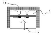
- It is a schematic diagram of the manufacturing method of the injection-molded body of Reference Example 6.
- It is a schematic diagram of the manufacturing method of the injection-molded body of Reference Example 6.
- It is a schematic diagram of the manufacturing method of the injection-molded body of Reference Example 6.
- It is a schematic diagram of the manufacturing method of the injection-molded body of Reference Example 6.
- Infrared heater 2 Infrared 3: Resin sheet having heat shrinkability 4: High-concentration infrared-absorbing ink printing unit 5: Low-concentration infrared-absorbing ink printing unit 6: Color ink printing unit 7 (does not absorb infrared rays) 7: Injection molding resin 8: Ink G1 9: Ink G2 10: Ink GH1 11: Ink GH2 12: Ink GH3 13: Ink GH4 14: Ink G4 15: Mold for injection molding 16: Surface protective layer
Landscapes
- Engineering & Computer Science (AREA)
- Manufacturing & Machinery (AREA)
- Mechanical Engineering (AREA)
- Physics & Mathematics (AREA)
- Thermal Sciences (AREA)
- Health & Medical Sciences (AREA)
- Toxicology (AREA)
- Laminated Bodies (AREA)
- Moulds For Moulding Plastics Or The Like (AREA)
- Injection Moulding Of Plastics Or The Like (AREA)
- Blow-Moulding Or Thermoforming Of Plastics Or The Like (AREA)
- Shaping Of Tube Ends By Bending Or Straightening (AREA)
Abstract
Description
また、賦型シートやエンボス加工あるいはシュライナー加工等の加熱した彫刻ロールの接圧により物理的に予めシート表面に凹凸を施した賦型シートを射出成形用金型内に装着し、射出成形後剥離して凹凸を賦型する方法等が知られている。これはシート製造工程においてエンボス装置や特殊印刷工程を必要とするため高コストであったり、凹凸の模様に応じて版を作り替える必要があった。また巻きの状態で既に凹凸が生じていることから巻きズレ不良が起こりやすいこと、凸部分の重ね合わせによるゲージバンド不良が発生し易いこと等取り扱いの点での問題や、射出成形時の高い樹脂温度に曝露されたエンボス加工部が配向戻りによる塑性変形を起こし所望の凹凸が得られないといった問題があった。
賦型シートは、表面に形成された赤外線吸収性の異なる部位Aと部位Bを有する熱収縮性を有する樹脂シートを、保持した状態で、前記部位Aと前記部位Bとが、前記部位Aと前記部位Bとの表面温度が異なり、且つ、少なくとも部位Aの表面温度が前記樹脂シートの配向戻り強度変曲点温度T以上の表面温度となるように赤外線照射して、前記部位Aと部位Bとに膜厚差を生じさせることで得られる。
本発明者らは、該熱収縮性を有する樹脂シートを保持した状態で、且つ、該樹脂シートの同一面内にある複数の部位が異なる表面温度となるように、且つ、複数の部位の少なくとも1つの表面温度が前記樹脂シートの配向戻り強度変曲点温度T以上の表面温度となるように加熱すると、複数の部位のシート挙動が異なる結果各々の部位に膜厚差を生じることを見出した。本発明はこのシートの温度差を利用することで、膜厚差即ち凹凸を故意的に生じさせることに成功した。
赤外線吸収インキは赤外線吸収剤等を含有するインキであり、照射された赤外線を吸収し発熱する。即ち赤外線吸収インキで印刷された樹脂シートに赤外線を照射すると、前記赤外線吸収インキで印刷された部位のみに、赤外線照射で付与される熱量以上の熱量が加わる。
一方、赤外線反射インキは赤外線反射物質を含有するインキであり、照射された赤外線を反射する。赤外線反射インキで印刷された樹脂シートに該樹脂シート側(即ち樹脂シートの印刷面とは反対側の面)から赤外線を照射すると、該樹脂シートを通過した赤外線が該赤外線反射インキで反射されることにより、赤外線透過部位と反射部位とが重なる印刷部位のみに、赤外線照射で付与される熱量以上の熱量が加わる(これは具体的には、絵柄を設けない部位Bと比較し、部位Aはより効率よくシートへ熱を供給できる結果、と推定している)。
即ち、赤外線吸収インキ又は赤外線反射インキを印刷した部位のみに、赤外線照射で付与される熱量以上の熱量が加わるため、該部位の表面温度を高くすることができ、結果、樹脂シートの、赤外線吸収インキで印刷された部位と印刷されない部位とに温度差を生じさせることができる。
この場合、部位A及び部位Bともに赤外線照射で付与される熱量以上の熱量が加わるが、部位Aは部位Bよりインキ濃度が高い結果、より熱が加わる。従って、部位Aのほうが相対的に部位Bよりも表面温度が高くなる。
前記赤外線吸収または反射率の高いインキで絵柄を設けた部位Aと前記赤外線吸収または反射率の低いインキで絵柄を設けた部分Bとが異なる表面温度となるようにする。
この場合、部位A及び部位Bともに赤外線照射で付与される熱量以上の熱量が加わるが、部位Aは部位Bよりも赤外線吸収または反射率の高いインキを設けた結果、より熱が加わる。従って、部位Aのほうが相対的に部位Bよりも表面温度が高くなる。
本発明の賦型シートは、プリフォームを行わない状態では両面に凹凸が生じており、プリフォームを行った状態では片面に凹凸が生じており、いずれの状態でも射出成形用の賦型シートとして使用することができる。
本発明の賦型シートは、シート自体が内部応力が緩和された凹凸形状となっているので、プリフォーム、あるいは射出成形による加熱や圧力によっても凹凸が緩和され抜け落ちることがなく、射出成型体に複雑な凹凸を正確に再現することが可能である。従って射出成形用金型に挿入された状態で射出成形した後剥離することで、射出成形体表面に凹凸を賦型できる。
本発明において凹凸の形成は、前述の通り、熱収縮性を有する樹脂シートを保持した状態で、該樹脂シートの同一面内にある隣り合う部位Aと部位Bとが異なる表面温度となることで生じる。本発明においては、相対的に表面温度の高い部位を部位A、相対的に表面温度の低い部位を部位Bと定義する。この時部位Aは相対的に凹部となり部位Bは相対的に凸部となる。
この自己収縮挙動による厚み変化は、樹脂シートを保持しない状態では、起点を持たず全体的に収縮が起こり全体的に厚くなる傾向があるが、樹脂シートをクランプ等で保持した状態では、温度の低いクランプ部分等を起点に収縮が発生する傾向がありこの結果部位Aの薄膜化が発生すると考えられる。従って、部位Aは赤外線照射前、即ち収縮前の樹脂シートの膜厚よりも薄くなる場合が多い。
前記色インキ印刷部6を使用せずに非印刷部を有する樹脂シートの場合は、高濃度の赤外線吸収インキ印刷部が凹部となり、低濃度の赤外線吸収インキ印刷部が低い凸部、非印刷部が最も高い凸部となる。(図不示)
このように相対的に薄膜化と厚膜化が生じるため、凹凸が生じる。
前記凹凸の高低差は表面荒さ計や膜厚計にて測定でき、表面凹凸の最も高い部分と最も低い部分の差(以下膜厚差という)が10μm程度であれば凹凸発現として認識できる。明瞭な凹凸を発現させるためには膜厚差が15μm程度であることが好ましく、更に好ましくは20μm以上である。一方膜厚差は展開倍率に比例し小さくなるため深い成形品程凹凸の膜厚差は下がる傾向にある。また、展開倍率が高い程凹凸各々の幅も広がる傾向にある。
柄の例としては、点描や線描(具体的には絵画や文字の輪郭、木目、ストライプ、ヘアライン模様等が挙げられる)で表現された描画や、ドットや幾何学模様、文字やマークそのものを浮き出したい場合にはその模様の面積が小さい物の方がより好ましい。勿論本発明においてはこの限りではなく、模様や文字等、模様状の全ての柄を表現することが可能である。
図3~図6に、本発明において凹凸で表現される柄模様の例を示す。黒部分が赤外線吸収インキ又は赤外線反射インキで絵柄印刷された部分である。図3はストライプ、図4はドット、図5は幾何学模様、図6は木目を表す。
本発明においては、前記温度の指標として「前記部位Aと前記部位Bとの表面温度」と定義しているが、前述の通り樹脂シートの前記部位Aと前記部位Bの熱挙動は前記部位Aと部位Bとの表面だけではなく内部まで均等に温度がかかった状態で生じるものと推定される。しかしながら内部温度を測定する手段はないために、表面温度で定義した。本発明において表面温度はNEC/Avio社製「サーモトレーサー9100」を使用した。
本発明で使用する熱収縮性を有する樹脂シート(以下樹脂シートSと略す)は、加熱により展延性を示しフィルム化可能な樹脂であり、更に配向戻り強度変曲点を有する樹脂シートである。更に真空成形時の展延性の容易さから熱可塑性樹脂シートであることが好ましい。
本発明における配向戻り強度変曲点温度とは、フィルムに外部から熱が加えられた時のフィルム温度であって、フィルム自体がこの温度になると延伸された分子が収縮し始めることにより、フィルム全体が収縮する温度であり、本発明においては、下記方法において配向戻り強度変曲点温度Tを定義している。
本発明においては前記熱収縮応力測定法を利用して、配向戻り強度と加熱温度との関係を示す右上がりグラフの凸となる変曲点の温度Tを求めた。凸となる変曲点が複数ある場合は、最も高い温度域の変曲点の温度を配向戻り強度変曲点温度Tとした。
具体的には、日理工業株式会社製D.N式ストレステスターを用い、電圧調整メモリを6とし、ヒーター温度を5℃刻みで昇温し、各測定温度での配向戻り応力を測定し、収縮応力が発現した後、配向戻り強度と加熱温度との関係を示すグラフの変曲点温度Tを求めた。図7に例を示した。図7は、東洋紡績株式会社製の二軸延伸PETシート「ソフトシャインX1130(膜厚125μm)」(実施例におけるシートS1)を測定したときのグラフである。該グラフの最も高い温度域の凸となる変曲点の温度T188℃を、シートS1の配向戻り強度変曲点温度Tとした。
また、使用される樹脂は、延伸可能な樹脂であれば特に限定はなく、例えば、ポリエチレンテレフタレートやポリブチレンテレフタレート等のポリエステル樹脂、ポリエチレンやポリプロピレン等のポリオレフィン樹脂、ポリ塩化ビニル、アクリル樹脂やポリスチレン樹脂、ナイロンやビニロン等を使用することができる。中でもポリエステル樹脂が延伸後の厚みの均一性が良好な事から好ましい。
前記(1)~(3)の手段で使用する赤外線吸収インキ又は赤外線反射インキについて説明する。
赤外線吸収インキとは赤外線吸収剤を含むインキであり、赤外線反射インキは赤外線反射物質を含有するインキであり、いずれもセキュリティインキ等に利用されているインキである。
前述の通り、赤外線吸収インキは照射された赤外線を吸収し発熱する。即ち赤外線吸収インキで印刷された樹脂シートに赤外線を照射すると、前記赤外線吸収インキで印刷された部位のみに、赤外線照射で付与される熱量以上の熱量が加わる。一方、赤外線反射インキは赤外線反射物質を含有するインキであり、照射された赤外線を反射する。赤外線反射インキで印刷された樹脂シートに該樹脂シート側(即ち樹脂シートの印刷面とは反対側の面)から赤外線を照射すると、該樹脂シートを通過した赤外線が該赤外線反射インキで反射されることにより、赤外線透過部位と反射部位とが重なる印刷部位のみに、赤外線照射で付与される熱量以上の熱量が加わる。即ち、赤外線吸収インキ又は赤外線反射インキを印刷した部位のみに、赤外線照射で付与される熱量以上の熱量が加わるため、該部位の表面温度を高くすることができ、結果、樹脂シートの、赤外線吸収インキで印刷された部位と印刷されない部位とに温度差を生じさせることができる。
部位Aのみが配向戻り強度変曲点温度T以上の表面温度となるように赤外線照射してもよく、また、部位Aと部位Bの両方が配向戻り強度変曲点温度T以上の表面温度となるように赤外線照射してもよい。この場合、後者のほうがより深い凹凸を得ることができる。
一方、前記インキ濃度は、濃度が高い程部位Aにかかる熱量が大きくなる。従って所望する凹凸の程度により適宜含有量を変えることが好ましい。一方濃度が低すぎると赤外線照射により発生する熱量や赤外線反射量が少なすぎて凹部とならず、濃度が高すぎると発生する熱量や赤外線反射量が大きくなりすぎて、破れや穴あき等の原因となるので、後述の通り成形時の弾性率が0.5MPa以下にならない様に適宜調整をする必要がある。
通常は、図1のように、赤外線が樹脂シートを透過して赤外線吸収インキ又は赤外線反射インキ層に到達するように照射する。特に赤外線反射インキを使用した場合には、このような照射方法としないと、逆に赤外線反射インキが樹脂シートを透過する前に赤外線を反射してしまい、即ち樹脂シートの印刷部に赤外線が透過せずに可塑化されない可能性がある。
前記(2)の手段は、具体的には、インキ濃度の異なるインキを使用して部位A及び部位Bを設ける、あるいは、インキは1種であるがそのインキ盛り量を部位Aにより多くするなどの方法により、インキ濃度を調整することが可能である。
また、部位Aは1つである必要はなく、例えば、インキ濃度の異なる3種のインキを使用した場合、濃度の最も低いインキを使用した部位は部位Bとなり凸部となり、濃度の最も高いインキを使用した部位は最も深い凹部である部位A”となる。またインキ盛り量で調節することも勿論可能である。
前記赤外線吸収インキの吸収率、あるいは赤外線反射インキの反射率は一概には比較できないが、大まかな目安としては、アルミニウムを使用した赤外線反射インキとカーボンブラックを使用した赤外線吸収インキを併用した場合には、アルミニウムを使用したインキが凹部となりカーボンブラックを使用したインキは凸部となる。またカーボンブラックを使用した赤外線吸収インキと酸化チタンを使用した赤外線吸収インキとを併用した場合には、カーボンブラックを使用したインキが凹部となり酸化チタンを使用したインキは凸部となる。
従って、具体的には、部位Aをアルミニウムを含むインキで印刷し、部位Bをカーボンブラックを含むインキで印刷すれば、部位Aは凹部となり部位Bが凸部となる。また、部位Aをカーボンブラックを含むインキで印刷し、部位Bを酸化チタンを含むインキで印刷すれば、部位Aは凹部となり部位Bが凸部となる。このように、熱発生物質は、所望する凹凸意匠と視認性を有する絵柄意匠とを加味して適宜選択することが可能である。
また赤外線吸収インキであって濃度の低いインキと濃度の高いインキとを使用して印刷を行い、且つ非印刷部を設けた場合は、濃度の高いインキの刷り部位が最も深い凹部であり、濃度の低いインキを使用の刷り部位が前記濃度の高いインキの刷りの部位からみると凸部であり非印刷部からみると凹部であり、且つ非印刷部が凸部であるような凹凸を与えることができる。
前記樹脂シートSに、射出成形体に転写可能な絵柄層を設けることもできる。例えば、前記樹脂シートS/前記離型層/凹凸を生じさせる前記赤外線吸収インキや赤外線反射インキの順に積層された賦型シートは、射出成形用金型に挿入された状態で射出成形した後剥離すると、離型層と前記赤外線吸収インキや赤外線反射インキのとの間で剥離するために、前記赤外線吸収インキや赤外線反射インキは射出成形体に転写され、即ち、凹凸に沿って絵柄を有する加飾された射出成形体を得ることができる。この際、所望する意匠性に応じて、前記赤外線吸収インキ又は赤外線反射インキに汎用の色材等を含有してもよい。このとき、前記赤外線吸収剤や赤外線反射物質として透明性の高いものを使用すれば、汎用の色材を生かすことができ好ましい。また版を変えて汎用の色材を含有したインキで別途絵柄層を設けてもよい。この場合に使用する色材は特に限定はないが、熱吸収性を有する色材は該印刷部分に凹凸を生じさせることも可能なため、目的に応じ適宜配合割合を変える事が好ましい。
また、前記赤外線吸収インキや赤外線反射インキだけでなく、通常の色インキ(赤外線を吸収あるいは反射することのない)も使用すると、凹凸に沿った絵柄以外の柄も転写することができる。
前記絵柄層を転写させる場合には、耐摩擦性、耐擦傷性、耐候性、耐汚染性、耐水性、耐薬品性及び耐熱性等の性能を付与するために、透明、半透明若しくは着色クリアの表面保護層を1層以上設けることもできる。表面保護層は、後述の離型層と、転写したい絵柄印刷層の間に配することが好ましい。これにより印刷層が表面保護層の下となり、得られる射出成形体の絵柄を保護することが可能となる。具体的には、樹脂シートS/離型層/透明な樹脂硬化層/転写したい絵柄印刷層/接着層の順に積層されていることが望ましい。このとき、赤外線吸収インキ又は赤外線反射インキ層も射出成形体表面に転写したい場合には、樹脂シートS/離型層/透明な樹脂硬化層/転写したい絵柄印刷層・赤外線吸収インキ又は赤外線反射インキ層/接着層の順に積層されていることが望ましい。
また前記樹脂シートSに離型層を設ける事も好ましく、表面保護層や熱発生物質を含むインキを射出成形体に容易に転写させることが可能となる。離型層は、樹脂シートSを剥離した際に、樹脂シートS本体とともに離型する。離型層の材質としては、エポキシ樹脂系離型剤、エポキシメラミン樹脂系離型剤、アミノアルキッド樹脂系離型剤、メラミン樹脂系離型剤、シリコーン樹脂系離型剤、フッ素樹脂系離型剤、セルロース誘導体系離型剤、尿素樹脂系離型剤、ポリオレフィン樹脂系離型剤、パラフィン系離型剤およびこれらの複合型離型剤などを用いることができる。更に離型層中に炭酸カルシウム、シリカ、酸化亜鉛、炭酸マグネシウム、ポリエチレンワックス、ガラスビーズなどの微粉末を含有させる事によりマット感を表現することが可能となる。
離型層を形成する方法としては、各種印刷法や塗工法などが好適に用いられる。
また、インキ層と射出成形体との接着性を高める目的で、熱転写シートに通常使用する接着層や粘着層を設けていてもよい。
接着層は、インキを射出成形用樹脂に良好に接着させる目的で任意に用いられるため射出成形用樹脂の種類に合わせて選定する必要があるが一般的な接着剤としては、例えば、アクリル樹脂、ウレタン樹脂、ウレタン変性ポリエステル樹脂、ポリエステル樹脂、エポキシ樹脂、エチレン-酢酸ビニル共重合樹脂(EVA)、塩化ビニル樹脂、塩化ビニル-酢酸ビニル共重合樹脂、天然ゴム、SBR、NBR、シリコーンゴム等の合成ゴムなどがあげられ、溶剤型又は無溶剤型のものが使用出来る。
その他、必要に応じて、本発明の効果を損なわない範囲において任意の層を有していても良い。
本発明の賦型シートは、具体的には、前記(1)~(3)の手段を施した表面に形成された赤外線吸収性の異なる部位Aと部位Bを有する樹脂シートSを、保持した状態で、前記部位Aと前記部位Bとが、前記部位Aと前記部位Bとの表面温度が異なり、且つ、少なくとも部位Aの表面温度が前記樹脂シートの配向戻り強度変曲点温度T以上の表面温度となるように、赤外線照射して、前記部位Aと部位Bとに膜厚差を生じさせることにより得られる。
前記工程1において、保持した状態とは、前述の通り、該樹脂シートS外周の一部のみもしくは外周全部を固定した状態、即ち、該シートSの射出成形用樹脂と接する面は基板等でなんら支持されない状態を指す。具体的には、樹脂シートSの一部分を挟持等で固定する方法や樹脂シートSの全周囲を枠状クランプで挟持させ固定する方法等が挙げられるが、樹脂シートSの張力を適正化(均一化)することができるためシートの全周囲を枠状クランプで挟持させ固定する方法が好ましい。
なおここで固定とは、枠状クランプ等のジグを使用して挟持する方法の他、樹脂シートSの可塑化や収縮を防止することによっても可能である。具体的には、樹脂シートSの射出成形用樹脂と接する面以外の部分、好ましくはシート外周部位のシート温度をガラス転移温度(以下Tgと称する場合がある)以下に保ち可塑化を防ぐことによっても、固定が可能である。
前記樹脂シートSを保持した状態で、少なくとも部位Aの表面温度が前記樹脂シートの配向戻り強度変曲点温度T以上の表面温度となるように赤外線照射することで、前記部位Aと前記部位Bとが異なる表面温度となって加温され、結果、前記部位Aと部位Bとに膜厚差が生じる。
このとき照射する赤外線は、赤色から近赤外、赤外レーザー光の波長域であれば特に限定はなく使用できる。赤外線照射量の上限は、特に制限はないが、あまり高い熱量がかかると樹脂シートSの剛性が落ち、可塑化が進み破れ発生等、成形に支障をきたすおそれがあるため、使用する樹脂シートSの最も高い部分の温度が、JIS K7244-1法で求められる動的粘弾性測定の貯蔵弾性率(E’)の値として0.5MPa以上となる様にすることが好ましく、より好ましくは1MPa以上となるように照射量を設定することが好ましい。
赤外線照射装置としては、樹脂シートSを保持した状態で照射できるものであればオーブンやヒーター等何でもよい。また本発明の賦型シートは、後述の通り、真空成形下で赤外線照射することにより効率よく凹凸の発現が可能となることから、真空成形法、圧空真空成形法等に用いる既存の間接加熱型熱成形機を利用することは好ましい。シートの加熱を行う赤外線照射装置は熱発生物質のみが吸収可能な波長を照射する必要があるため、中赤外から近赤外の領域に強い波長ピークをもつハロゲンヒーター、短波長ヒーター、カーボンヒーター、中赤外線ヒーター等を使用することが好ましい。これら赤外線照射装置のメイン波長のピークは1.0~3.5μm内にあることが好ましく、効率よい膜厚さを生じさせることが出来、吸熱性物質とその他の部分の温度差が付きすぎず効率の良い生産が可能な事から1.5~3.0μmの範囲が更に好ましい。
赤外線照射の最低量は、樹脂シートSの少なくとも部位Aの表面温度が前記樹脂シートの配向戻り強度変曲点温度T以上の表面温度となるように設定する。一方、部位Aの温度は、あまり高い温度となると部位Aの可塑化が進み穴あき等の不良が発生するおそれがあることから、部位Aの動的粘弾性測定で測定されるE’が0.5MPa以上とするように、赤外線照射の最高量を設定することが好ましく、より好ましくは1.0MPa以下である。
プリフォームの型は、外しやすいことからステンレス等の金属製あるいはシリコン製を使用することが好ましい。また形状は特に限定はなく、平板、3次元形状等の型を使用することができる。
本発明の賦型シートを使用することにより、凹凸が賦型された射出成形体を得ることができる。
射出成形体の製造方法としては、例えば、前記賦型シート、または賦型シートのプリフォーム体を射出成形用金型内に装着し射出成形する工程と、前記射出成形後、前記膜厚差の生じた樹脂シートを剥離する工程とにより得ることが出来る。
射出成形に使用する樹脂は特に限定はなく、公知の射出成形樹脂が使用できる。具体的には、ABS樹脂、PVC(ポリ塩化ビニル)/ABS樹脂、PA(ポリアミド)/ABS樹脂、PC(ポリカーボネート)/ABS樹脂、PBT(ポリブチレンテレフタレート)/ABS等のABS系のポリマーアロイ、AAS(アクリロニトリル・アクリルゴム・スチレン)樹脂、AS(アクリロニトリル・スチレン)樹脂、AES(アクリロニトリル・エチレンゴム・スチレン)樹脂、MS((メタ)アクリル酸エステル・スチレン系樹脂、PC系樹脂、PMMA(ポリメチルメタクリレート)系樹脂、PP(ポリプロピレン)系樹脂、等が挙げられる。
更に、成形性が阻害されない範囲で慣用の添加剤を添加してもよく、例えば、可塑剤、耐光性添加剤(紫外線吸収剤、安定剤等)、酸化防止剤、オゾン化防止剤、活性剤、耐電防止剤、滑剤、耐摩擦剤、表面調節剤(レベリング剤、消泡剤、ブロッキング防止剤等)、防カビ剤、抗菌剤、分散剤、難燃剤及び加流促進剤や加流促進助剤等の添加剤を配合してもよい。これら添加剤は単独で使用しても2種類以上を併用してもよい。
用いる着色剤は、特に限定されず、目的とする意匠に合わせて、一般の熱可塑性樹脂の着色に使用される慣用の無機顔料、有機顔料および染料などが使用できる。例えば、酸化チタン、チタンイエロー、酸化鉄、複合酸化物系顔料、群青、コバルトブルー、酸化クロム、バナジウム酸ビスマス、カーボンブラック、酸化亜鉛、炭酸カルシウム、硫酸バリウム、シリカ、タルク等の無機顔料;アゾ系顔料、フタロシアニン系顔料、キナクリドン系顔料、ジオキサジン系顔料、アンスラキノン系顔料、イソインドリノン系顔料、イソインドリン系顔料、ペリレン系顔料、ペリノン系顔料、キノフタロン系顔料、チオインジゴ系顔料及びジケトピロロピロール系顔料等の有機顔料;金属錯体顔料などが挙げられる。また染料としては主として油溶性染料のグループから選ばれる1種または2種を使用することが好ましい。
金型温度はポリプロピレン樹脂やABS樹脂のインサート成形ではキャビティー側金型、コア側金型ともに水冷~100℃程度の温調で良いが、インサート成形後の被転写体の形状によっては反りを生じる場合があり、こうした場合にはキャビティー側金型とコア側金型に温度差を設けた金型温調を行なっても良い。また金型内に挿入した装飾シートを射出成形用樹脂の充填前に金型温度まで加温するために、型締めした金型内で1~100秒の範囲で保持させる射出遅延時間を設定しても良い。
射出成形用樹脂の樹脂温度は特に制限されるものではないが、ポリプロピレン系樹脂、ABS系樹脂等の熱可塑性樹脂であれば、射出可能な180~250℃程度が好ましい。
また、赤外線照射できるような近赤外線、中赤外線領域の波長を放出するヒーターを内部に備えたインサート成形用射出成形機を使用し、インサートフィルムの設置箇所に、表面に形成された赤外線吸収性の異なる部位Aと部位Bを有する熱収縮性を有する樹脂シートを設置し、赤外線照射して凹凸を生じさせた後射出成形することで、本発明の賦型シートを利用し、表面に凹凸を有する射出成形体の連続生産が可能となる。更にインサートフィルムを使用する場合は、本発明の賦型シートと射出成形用樹脂との間に設置する。
得られた射出成形体から、賦型シートを剥離する。剥離方法は特に限定はなく、例えば、境界端面を浮き上がらせ、引き剥がせばよい。境界端面を浮き上げ難い場合は、粘着テープ等を貼り付けて、剥離端を作ってから引き剥がしてもよい。尚、賦型シートと射出成型樹脂が同系列の樹脂である場合、熱融着による接着が起こってしまい、剥離が困難になる。このように接着性が強く剥離が困難となる場合には、剥離層を設ける事が好ましい。
樹脂シートSとしては、以下のシートを使用した。
シートS0:東洋紡績株式会社製の二軸延伸PETシート「ソフトシャインX1130」(膜厚188μm)
シートS1:東洋紡績株式会社製の二軸延伸PETシート「ソフトシャインX1130」(膜厚125μm)
シートS2:帝人デュポンフィルム株式会社製の二軸延伸PETシート「テフレックスFT3NC3」(膜厚50μm)
シートS3:二軸延伸ポリスチレンシート(膜厚250μm)「DIC社製ポリスチレンCR-4500」を押出機用いて210℃にて押出後、Tダイから無延伸原反を成膜した。その後、130℃の温度条件で延伸加工を行いMD方向0.4Mpa、TD方向0.5Mpaの熱収縮応力を持つ膜厚250μmの延伸シートとした
シートS4:ポリテック社製の未延伸シート「A-PET PT700M」(膜厚250μm)
インサートフィルム:日本デコール株式会社製熱転写型剥離性フィルムOPETシート 「T9116-05」(膜厚52μm)。ヘアライン転写印刷層及びトップコート層とを転写層に有し、被着体に転写後トップコート層をUV硬化させる。
エンボスシート:日本デコール株式会社製エンボス化粧シート(事前に熱ロールにより凹凸が付与されている) サニークロス-05E(膜厚140μm)
前記樹脂シートSの配向戻り強度変曲点温度Tは、以下のように行った。
日理工業株式会社製D.N式ストレステスターを用い、電圧調整メモリを6とし、ヒーター温度を5℃刻みで昇温し、各測定温度での配向戻り応力を測定し、配向戻り強度変曲点温度Tを読み取った。
結果、
シートS0の配向戻り強度変曲点温度T: 188℃
シートS1の配向戻り強度変曲点温度T: 188℃
シートS2の配向戻り強度変曲点温度T: 170℃
シートS3の配向戻り強度変曲点温度T: 109℃
シートS5の配向戻り強度変曲点温度T: 無し
赤外線吸収インキ又は赤外線反射インキ、及び色インキは以下のインキを使用した。
インキP1:三菱鉛筆社製「ペイントマーカー」黒色 赤外線吸収インキとして使用。
インキP2:三菱鉛筆社製「ペイントマーカー」銀色 赤外線反射インキとして使用。
インキP3:三菱鉛筆社製「ペイントマーカー」青色 色インキとして使用。
インキG1:DICグラフィクス社製グラビア印刷用インキ「NH-NT」黒色 カーボンブラックを含み赤外線吸収インキとして使用。
インキG2:DICグラフィクス社製グラビア印刷用インキ「NH-NT」銀色 アルミペーストを含み赤外線反射インキとして使用。
インキGH1:DIC社製グラビア印刷用インキ「XS-756」赤色 色インキとして使用。
インキGH2:DIC社製グラビア印刷用インキ「XS-756」青色 色インキとして使用
インキGH3:DIC社製グラビア印刷用インキ「XS-756」黄色 色インキとして使用
インキGH4:DIC社製グラビア印刷用インキ「XS-756」パール色 色インキとして使用
なお、前記インキG1とインキG2では、G2のほうが表面温度が高くなる。
樹脂シートSとしてシートS1~シートS3のいずれかを使用し、流れ方向(MD)及びクロス方向(CD)に、前記インキP1~P3を使用して幅2mmの直線を描いた。これを布施真空株式会社製「NGF-0709成形機」を使用し、真空下、シート周囲を完全にクランプで固定した状態で、ヒーターとしてヘリウス社製中赤外線ヒーターを使用し前記樹脂シートSを前記直線を描いた面とは反対側から間接加熱した。
キーエンス社製FT-H30放射温度計にて、樹脂シートSの表面温度がヒーター設定温度まで上昇したことを確認した後、常温まで冷却しクランプをはずして試料とした。
インキが描かれている部位Aとインキが描かれていない部位Bの表面温度は、NEC/Avio社製サーモトレーサーTH9100を使用して、前記部位Aが、使用する樹脂シートSの配向戻り強度変曲点温度Tとなった時の、前記部位Aと前記部位Bの温度差/℃と、使用する樹脂シートSの表面温度がヒーター設定温度まで上昇した時(該温度は、通常、熱成形が可能となったことを判断する温度である)の、前記部位Aと前記部位Bの温度を測定した。
また、前記部位Aと前記部位Bの膜厚の測定は、アンリツ社製K351C、高低差測定は東京精密社製サーフコムver1.71表面粗さ系を使用し、前記部位Aと前記部位Bとの最大膜厚差を測定した。
以下、シートS1~S3と、インキP1~P2の組み合わせを表1に従い適宜変更したものを、参考例とした。結果を表1-1、表1-2及び表2に示す。


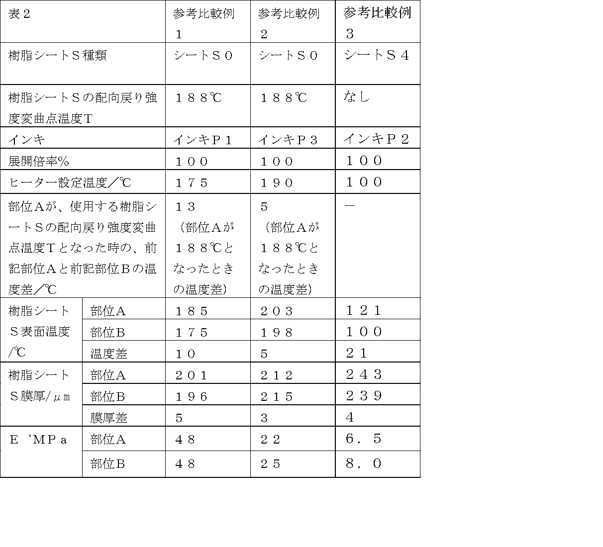
参考比較例1は、シートの配向戻り強度変曲点温度よりも部位Aの温度が低い例であるが、凹凸を発現させることができなかった。
また参考比較例2は、色インキを使用したものであるが、部位Aが配向度戻り開始点温度以上になったにもかかわらず凹凸を発現させることができなかった。
また、参考比較例3は、熱収縮性を示さない(配向戻り強度変曲点温度がない)シートS4を使用した例である。ヒーターの設定温度はS4の熱軟化点を超える温度であり、成形は問題なくできる温度であるが、凹凸を発現させることができなかった。
射出成形用樹脂P1:日本A&L社製 クララスチック GA-501 射出成形用樹脂温240℃
射出成形用樹脂P2:帝人化成社製 マルチロン T-3714 射出成形用樹脂温270℃
射出成形用樹脂P3:DIC株式会社製 ディクスチレンXC520 射出成形用樹脂温 220℃
前記樹脂シートSに、前記インキG1又はG2を使用して、グラビア4色印刷機にて厚さ3μmの絵柄を印刷した。
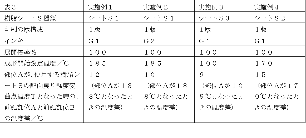
樹脂シートSとしてシートS1を使用し、インキG1でグラビア印刷にて所定の絵柄印刷を行った(図8参照)。周囲をクランプ後、布施真空株式会社製「NGF-0709成形機」の上下ボックスを閉じ、ボックス内をほぼ完全真空状態にした後、ヒーターとしてヘリウス社製中赤外線ヒーターを使用し前記樹脂シートSを上面より間接加熱を行った。前記樹脂シートS1の表面温度を成形開始設定温度まで上昇した後に、常温まで冷却しクランプをはずし、印刷面、非印刷面とも凹凸状態になっている賦型シート(1)を得た(図9参照)。
樹脂シートSとしてシートS1を使用し、インキG2でグラビア印刷にて所定の絵柄印刷を行った(図8参照)。周囲をクランプ後、布施真空株式会社製「NGF-0709成形機」の上下ボックスを閉じ、ボックス内をほぼ完全真空状態にした後、ヒーターとしてヘリウス社製中赤外線ヒーターを使用し前記樹脂シートSを上面より間接加熱を行った。その後平滑なステンレス板を乗せたテーブルを上昇させ、上ボックス中に0.2MPaの圧空を吹き込み、前記樹脂シートSの非印刷面をステンレス板に押し当て、プリフォームされ、印刷面のみが凹凸となっている賦型シート(2)を得た(図10参照)。
樹脂シートSとしてシートS3を使用し、インキG1でグラビア印刷にて所定の絵柄印刷を行った(図8参照)。
実施例2と同様にして、プリフォームされ、印刷面のみが凹凸となっている賦型シート(3)を得た(図10参照)。
樹脂シートSとしてシートS2を使用し、インキG1でグラビア印刷にて所定の絵柄印刷を行った(図8参照)。
実施例2と同様にして、プリフォームされ、印刷面のみが凹凸となっている賦型シート(4)を得た(図10参照)。
前記実施例1~4で得た賦型シート(1)~(4)を、インキ層と反対側の面が射出成形用金型の雌型に接触するように密着させ金型温度50℃で加熱後、射出成形用樹脂P1~P3のいずれかを所定の射出成形用樹脂温に加熱し金型内に射出して一体成形した。金型から取り出し後賦型シートを剥離し、射出成形体(1)~(4)を作成した。なお、射出成形機は東芝機械(株)製のEC75N-1.5Yを用いた。射出成形金型は、99.5(L)×99.5(W)×12.5(H)mm、コーナーR=10mm、立ち上がり部のR=5R、抜き勾配18.5°のトレー状の型Aを用いた。
得られた参考例1~4の射出成形体の凹凸差再現性、耐擦傷性評価は以下のように行った。
○:加飾射出成型品凹凸差/射出成形前フィルム最大凹凸差×100で表される凹凸転写率90%以上。
△:加飾射出成型品凹凸差/射出成形前フィルム最大凹凸差×100で表される凹凸転写率90%未満
×:加飾射出成型品凹凸差/射出成形前フィルム最大凹凸差×100で表される凹凸転写率30%未満
尚、射出成形前フィルム最大凹凸は、樹脂シートSの状態もしくは賦型シートとしたときの状態のうち最も膜厚差がある状態での膜厚差値とした。
ラビングテスター(大平理化工業株式会社製)を用いて、射出成形体表面に5%クレンザー溶液を十分に脱脂綿に染み込ませてから載せ、その上を試験機端子で押さえ、1kgの荷重をかけて30往復した後、水洗し直ちにタオルドライし、塗面を目視評価した。評価は賦型シート無しで作成した同一樹脂比較板との差とした。用いた基準は以下の通りである。
△:比較板に比べツヤビケが少し認められた。
×:ツヤビケが著しく認められた。
結果を表4に示す。

実施例2で得た賦型シート(2)と日本デコール株式会社製のインサートフィルム「T9116-05」とを、前記賦型シート(2)のインキ層と反対側の面が射出成形用金型の雌型に接触するように密着させ、且つ賦型シート(2)のインキ層とインサートフィルムのインキ層と反対側の面とが合うように重ね合わせた状態で、金型内に装着した。
金型温度50℃で加熱後、射出成形用樹脂P2を所定の射出成形用樹脂温に加熱し金型内に射出して一体成形した。金型から取り出し後賦型シート及びインサートフィルムの離型フィルムを剥離し、ヘアライン印刷層とトップコート層とが転写印刷された射出成形体(5)を作成した。その後、インサートフィルムから転写されたトップコート層を、GSユアサ株式会社製の高圧水銀灯(主波長は254nm、313nm、365nm、405nm、436nm、546nm、577nm)を装着したGSユアサ株式会社製のUV照射装置を使用し、照射量1000mJ/cm2、ピーク強度200mW/cm2のUV光を照射することにより硬化させた。結果を表5に示す。

樹脂シートSとしてシートS2を使用した。表面保護層を塗布したシートS2の該表面保護層(以下TPと称す)の上に、インキG1、GH1、GH2、GH4でグラビア印刷にて所定の絵柄印刷を行った(図11参照)。
前記シートS2の印刷面をステンレス板に押し当てた以外は実施例2と同様にして、プリフォームされ、非印刷面のみが凹凸となっている賦型シート(6)を得た(図12参照)。
参考例1~4と同様にして射出成形体(6)を得た(図13~図16参照)。
射出成形体(6)は、インキG1及びインキGH1が転写されていた。結果を表7に示す。
前記表面保護層は、水酸基含有共重合体とポリイソシアネート化合物を1:1の割合で混合したものを使用し、10μmの厚さに塗布した。
酢酸ブチル850部とパーブチルZ(商品名、日本油脂社製、t-ブチルパーオキシベンゾエート)1部の混合溶液中を110℃に加熱し、メチルメタクリレート660部、t-ブチルメタクリレート150部、2-ヒドロキシエチルメタクリレート190部の混合溶液、及び、酢酸イソブチル200部、パーブチルO(商品名、日本油脂社製、t-ブチルパーオキシ-2-エチルヘキサノエート)9部、パーブチルZ(商品名、日本油脂社製、t-ブチルパーオキシベンゾエート)2部の混合溶液を、窒素雰囲気下で約5時間かけて滴下混合した後、15時間攪拌し、固形分含有率60%の水酸基含有共重合体を得た。得られた樹脂の重量平均分子量は100,000、固形分の水酸基価は79KOHmg/g、ガラス転移温度Tgは95℃であった。ここで、重量平均分子量はGPC測定のポリスチレン換算値、水酸基価はモノマー仕込み組成よりKOH中和量としての算出値、ポリマーTgはDSCによる測定値である。
ポリイソシアネート化合物として、イソシアヌレート環含有ポリイソシアネート「BURNOCK DN-981」(商品名、DIC株式会社製、数平均分子量約1000、不揮発分75%(溶剤:酢酸エチル)、官能基数3、NCO濃度13~14%)を用いた。
樹脂シートSとしてシートS1を使用し、インキG1でグラビア印刷にて所定の絵柄印刷を行った(図8参照)。
周囲をクランプ後、布施真空株式会社製「NGF-0709成形機」の上下ボックスを閉じ、ボックス内をほぼ完全真空状態にした後、ヒーターとしてヘリウス社製中赤外線ヒーターを使用し前記樹脂シートSを上面より間接加熱を行った。99.5(L)×99.5(W)×12.5(H)mm、コーナーR=10mm、立ち上がり部のR=5R、抜き勾配18.5°のトレー状の型Aを用い、樹脂シートSの表面温度が成形開始設定温度まで上昇した後に、型Aを載せたテーブルを上昇させ、上ボックス中に0.2MPaの圧空を吹き込み、型Aでプリフォームされ、印刷面のみが凹凸となっている賦型シート(7)を得た。
前記賦型シート(7)を、前記型Aと同形状の射出成形用金型の雌型に接触するように密着させ金型温度50℃で加熱後、射出成形用樹脂P3を所定の射出成形用樹脂温に加熱し金型内に射出して一体成形した。金型から取り出し後賦型シート(7)を剥離し、射出成形体(7)を作成した。結果を表7に示す。

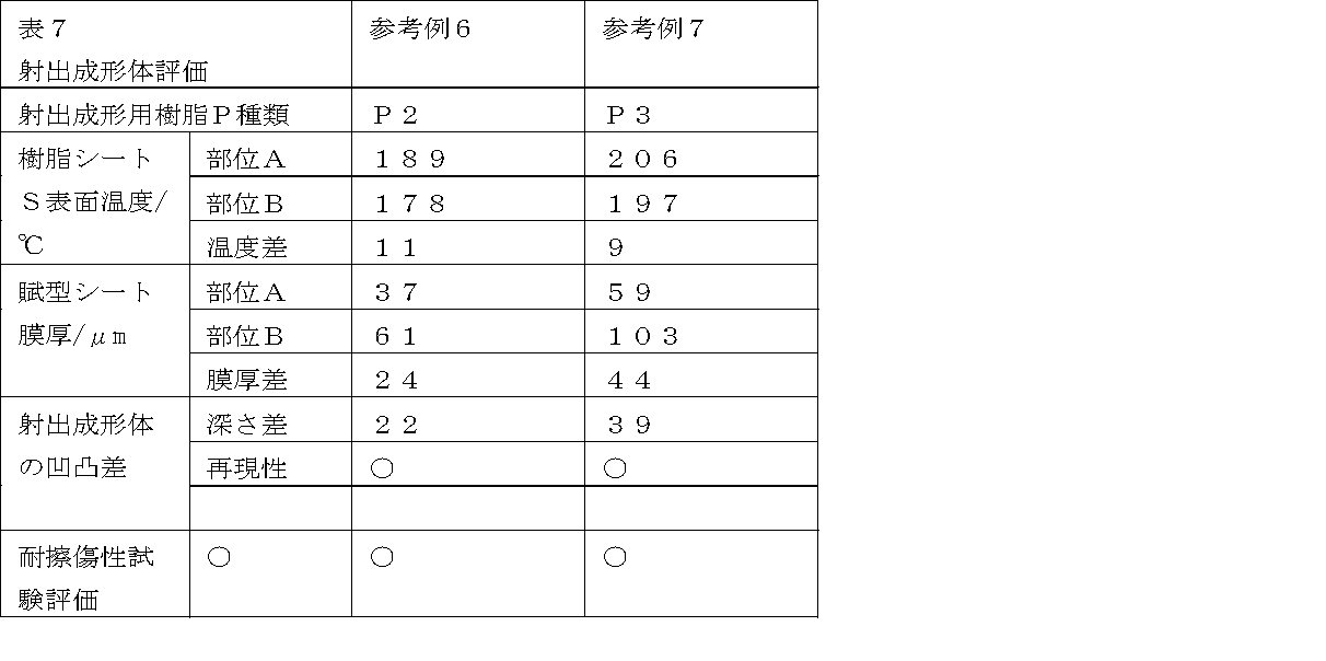
実施例1において、ヘリウス社製中赤外線ヒーターの代わりに所定の温度に加熱保温したタバイ社製ギアオーブンGPHH-100(加熱源は熱風である)に5分間投入した以外は実施例1と同様にして賦型シート(H1)を得た。
前記賦型シート(H1)を使用する以外は参考例1~4と同様にして射出成形体(H1)を得た。結果を表8に示す。その結果、膜厚差は生じず、凹凸を有する加飾成形体は得られなかった。

シートとして、日本デコール株式会社製のエンボス化粧シート「サニークロス-05E(膜厚140μm)」を用いた以外は実施例6と同様の方法で射出成形体(H2)を作製した。「サニークロス-05E」は事前に熱ロールにより凹凸が付与されているため、予備成形前のシートS6の凹凸深さ、予備成形後のシートS6の凹凸深さ、射出成形体(H2)の凹凸差を示した。また再現性評価に関しては、最も凹凸差のある「サニークロス-05E」の凹凸差を基準に評価を行った。その結果、プリフォーム作製時に凹凸が緩和されてしまい、射出成形体(H2)の凹凸差再現性評価が×であった。結果を表9に示す。

2:赤外線
3:熱収縮性を有する樹脂シート
4:高濃度の赤外線吸収インキ印刷部
5:低濃度の赤外線吸収インキ印刷部
6:(赤外線を吸収しない)色インキ印刷部
7:射出成形用樹脂
8:インキG1
9:インキG2
10:インキGH1
11:インキGH2
12:インキGH3
13:インキGH4
14:インキG4
15:射出成形用金型
16:表面保護層
Claims (9)
- 射出成形用金型に挿入された状態で射出成形した後剥離することで、射出成形体表面に凹凸を付与できる賦型シートであって、表面に形成された赤外線吸収性の異なる部位Aと部位Bを有する熱収縮性を有する樹脂シートを赤外線照射してなる部分的な膜厚差を有することを特徴とする賦型シート。
- 前記賦型シートが、赤外線吸収インキ又は赤外線反射インキで印刷した熱収縮性を有する樹脂シートを赤外線照射してなる部分的な膜厚差を有する、請求項1に記載の賦型シート。
- 前記熱収縮性を有する樹脂シートが二軸延伸性ポリエチレンテレフタレートである、請求項1又は2に記載の賦型シート。
- 前記熱収縮性を有する樹脂シートが転写可能な絵柄層を有する、請求項1~3のいずれかに記載の賦型シート。
- 請求項1~4のいずれかに記載の賦型シートの製造方法であって、表面に形成された赤外線吸収性の異なる部位Aと部位Bを有する熱収縮性を有する樹脂シートを、保持した状態で、前記部位Aと前記部位Bとが、前記部位Aと前記部位Bとの表面温度が異なり、且つ、少なくとも部位Aの表面温度が前記樹脂シートの配向戻り強度変曲点温度T以上の表面温度となるように、赤外線照射して、前記部位Aと部位Bとに膜厚差を生じさせることを特徴とする賦型シートの製造方法。
- 前記熱収縮性を有する樹脂シートが、赤外線吸収インキ又は赤外線反射インキで絵柄を設けており、前記赤外線吸収インキ又は赤外線反射インキで絵柄を設けた部位Aと絵柄を設けない部位Bとを有する、請求項5に記載の賦型シートの製造方法。
- 前記熱収縮性を有する樹脂シートが、赤外線吸収インキ又は赤外線反射インキで絵柄を設けており、前記インキ濃度の高い部位Aと前記インキ濃度の低い部位Bとを有する、請求項5に記載の賦型シートの製造方法。
- 前記熱収縮性を有する樹脂シートが、赤外線吸収率または反射率の異なる複数種の赤外線吸収インキ又は赤外線反射インキで絵柄を設けており、前記赤外線吸収または反射率の高いインキで絵柄を設けた部位Aと前記赤外線吸収または反射率の低いインキで絵柄を設けた部位Bとを有する、請求項5に記載の賦型シートの製造方法。
- 前記熱収縮性を有する樹脂シートが、二軸延伸性ポリエチレンテレフタレートである、請求項5~8のいずれかに記載の賦型シートの製造方法。
Priority Applications (4)
| Application Number | Priority Date | Filing Date | Title |
|---|---|---|---|
| US13/577,806 US20130052422A1 (en) | 2010-03-05 | 2011-02-28 | Patterning sheet and manufacturing method therefor |
| KR1020127005651A KR101369917B1 (ko) | 2010-03-05 | 2011-02-28 | 부형 시트 및 그 제조 방법 |
| JP2011524117A JP4919137B2 (ja) | 2010-03-05 | 2011-02-28 | 賦型シート及びその製造方法 |
| CN2011800053319A CN102695594A (zh) | 2010-03-05 | 2011-02-28 | 赋型片及其制造方法 |
Applications Claiming Priority (2)
| Application Number | Priority Date | Filing Date | Title |
|---|---|---|---|
| JP2010-049062 | 2010-03-05 | ||
| JP2010049062 | 2010-03-05 |
Publications (1)
| Publication Number | Publication Date |
|---|---|
| WO2011108482A1 true WO2011108482A1 (ja) | 2011-09-09 |
Family
ID=44542134
Family Applications (1)
| Application Number | Title | Priority Date | Filing Date |
|---|---|---|---|
| PCT/JP2011/054478 Ceased WO2011108482A1 (ja) | 2010-03-05 | 2011-02-28 | 賦型シート及びその製造方法 |
Country Status (6)
| Country | Link |
|---|---|
| US (1) | US20130052422A1 (ja) |
| JP (1) | JP4919137B2 (ja) |
| KR (1) | KR101369917B1 (ja) |
| CN (1) | CN102695594A (ja) |
| TW (1) | TW201139108A (ja) |
| WO (1) | WO2011108482A1 (ja) |
Families Citing this family (4)
| Publication number | Priority date | Publication date | Assignee | Title |
|---|---|---|---|---|
| US20130008591A1 (en) * | 2010-03-18 | 2013-01-10 | Kanemitsu Kondo | Resin film coating method and coating device |
| JP5898505B2 (ja) * | 2012-01-20 | 2016-04-06 | リンテック株式会社 | 硬質平面板貼合用樹脂シート、積層体及び表示体 |
| DE102018122448A1 (de) * | 2018-09-13 | 2020-03-19 | Yazaki Systems Technologies Gmbh | Schrumpffolie, Schrumpfschlauch, System und Verfahren zum Betrieb solch eines Systems |
| FR3103133A1 (fr) * | 2019-11-18 | 2021-05-21 | Airbus Operations (S.A.S.) | : enveloppe a bache coloree pour reparation de panneau composite et procede de coloration et reparation |
Citations (3)
| Publication number | Priority date | Publication date | Assignee | Title |
|---|---|---|---|---|
| JPS5059448A (ja) * | 1973-09-25 | 1975-05-22 | ||
| JPS53105558A (en) * | 1977-02-28 | 1978-09-13 | Dainippon Printing Co Ltd | Forming of relief pattern |
| WO2010113601A1 (ja) * | 2009-03-31 | 2010-10-07 | Dic株式会社 | 加飾成形体の製造方法 |
Family Cites Families (7)
| Publication number | Priority date | Publication date | Assignee | Title |
|---|---|---|---|---|
| US4136224A (en) * | 1971-12-11 | 1979-01-23 | Dai Nippon Printing Co., Ltd. | Decorative laminated structures and method of making the same |
| US5976676A (en) * | 1996-01-10 | 1999-11-02 | Mitsubishi Polyester Film Corporation | Polyester film and decorative plate using same |
| JP3938253B2 (ja) * | 1997-12-26 | 2007-06-27 | 日本板硝子株式会社 | 樹脂正立等倍レンズアレイおよびその製造方法 |
| JP4156415B2 (ja) * | 2003-03-20 | 2008-09-24 | 大日本印刷株式会社 | 賦型方法、賦型フィルム、及び射出成形品 |
| DE102004041868B3 (de) * | 2004-08-27 | 2006-03-02 | Leonhard Kurz Gmbh & Co. Kg | Transferfolie, deren Verwendung sowie Verfahren zur Herstellung von dekorierten Kunststoffartikeln |
| JP4878837B2 (ja) * | 2005-12-28 | 2012-02-15 | 三菱樹脂株式会社 | 熱収縮性フィルム、並びにこの熱収縮性フィルムを用いた成形品、熱収縮性ラベル、及びこの成形品を用いた、又はこのラベルを装着した容器 |
| WO2011113601A1 (en) * | 2010-03-17 | 2011-09-22 | Biogenerix Ag | Method for obtaining biologically active recombinant human g-csf |
-
2011
- 2011-02-28 WO PCT/JP2011/054478 patent/WO2011108482A1/ja not_active Ceased
- 2011-02-28 US US13/577,806 patent/US20130052422A1/en not_active Abandoned
- 2011-02-28 KR KR1020127005651A patent/KR101369917B1/ko not_active Expired - Fee Related
- 2011-02-28 JP JP2011524117A patent/JP4919137B2/ja not_active Expired - Fee Related
- 2011-02-28 CN CN2011800053319A patent/CN102695594A/zh active Pending
- 2011-03-04 TW TW100107253A patent/TW201139108A/zh unknown
Patent Citations (3)
| Publication number | Priority date | Publication date | Assignee | Title |
|---|---|---|---|---|
| JPS5059448A (ja) * | 1973-09-25 | 1975-05-22 | ||
| JPS53105558A (en) * | 1977-02-28 | 1978-09-13 | Dainippon Printing Co Ltd | Forming of relief pattern |
| WO2010113601A1 (ja) * | 2009-03-31 | 2010-10-07 | Dic株式会社 | 加飾成形体の製造方法 |
Also Published As
| Publication number | Publication date |
|---|---|
| CN102695594A (zh) | 2012-09-26 |
| US20130052422A1 (en) | 2013-02-28 |
| TW201139108A (en) | 2011-11-16 |
| JP4919137B2 (ja) | 2012-04-18 |
| JPWO2011108482A1 (ja) | 2013-06-27 |
| KR20120055587A (ko) | 2012-05-31 |
| KR101369917B1 (ko) | 2014-03-06 |
Similar Documents
| Publication | Publication Date | Title |
|---|---|---|
| JP4609605B2 (ja) | 加飾成形体の製造方法 | |
| JP4811541B2 (ja) | 射出成形体の製造方法 | |
| TWI447021B (zh) | 耐箔毛邊性優異的轉印材之製法及轉印材 | |
| JP5223221B2 (ja) | 転写加飾シート、加飾成形品の製造方法及び加飾成形品 | |
| JP5244389B2 (ja) | 転写フィルムおよびその用途、並びに加飾樹脂製品の生産方法およびその使用 | |
| JP6163925B2 (ja) | マット調転写フィルム、及びそれを用いた成形品 | |
| JP4919137B2 (ja) | 賦型シート及びその製造方法 | |
| KR101103409B1 (ko) | 고광택 곡면 장식 패널 및 그 제조방법 | |
| JP6260219B2 (ja) | インモールド成形用転写フィルム及びそれを用いた成形品 | |
| JP5641307B2 (ja) | 凹凸模様を有する真空成形体の製造方法及び樹脂容器 | |
| JP2009274378A (ja) | フィルムインサート成形用フィルム、及び、成形品 | |
| JP5531686B2 (ja) | 熱成形用加飾シート及び加飾成形体の製造方法 | |
| JP2019038233A (ja) | 装飾シート、装飾シートを含む構造体及び装飾シートの製造方法 | |
| JP5641306B2 (ja) | 加飾成形体の製造方法 | |
| JP5641313B2 (ja) | 裏面加飾用積層シート、裏面加飾体及び裏面加飾体の製造方法 | |
| JP6794916B2 (ja) | 転写シート、転写シートの製造方法及び加飾成形品の製造方法 | |
| JP2012000781A (ja) | 表面に凹凸を有する化粧シートの製造方法 | |
| JP2012116128A (ja) | 二次加工用化粧シートおよびそれを用いた化粧材の製造方法 | |
| JP5825777B2 (ja) | 化粧シートおよび化粧シート被覆成形体の製造方法 |
Legal Events
| Date | Code | Title | Description |
|---|---|---|---|
| WWE | Wipo information: entry into national phase |
Ref document number: 2011524117 Country of ref document: JP |
|
| 121 | Ep: the epo has been informed by wipo that ep was designated in this application |
Ref document number: 11750592 Country of ref document: EP Kind code of ref document: A1 |
|
| ENP | Entry into the national phase |
Ref document number: 20127005651 Country of ref document: KR Kind code of ref document: A |
|
| NENP | Non-entry into the national phase |
Ref country code: DE |
|
| WWE | Wipo information: entry into national phase |
Ref document number: 13577806 Country of ref document: US |
|
| 122 | Ep: pct application non-entry in european phase |
Ref document number: 11750592 Country of ref document: EP Kind code of ref document: A1 |