WO2011108455A1 - リチウム二次電池 - Google Patents
リチウム二次電池 Download PDFInfo
- Publication number
- WO2011108455A1 WO2011108455A1 PCT/JP2011/054300 JP2011054300W WO2011108455A1 WO 2011108455 A1 WO2011108455 A1 WO 2011108455A1 JP 2011054300 W JP2011054300 W JP 2011054300W WO 2011108455 A1 WO2011108455 A1 WO 2011108455A1
- Authority
- WO
- WIPO (PCT)
- Prior art keywords
- negative electrode
- battery
- lithium
- oxide
- active material
- Prior art date
- Legal status (The legal status is an assumption and is not a legal conclusion. Google has not performed a legal analysis and makes no representation as to the accuracy of the status listed.)
- Ceased
Links
Images

Classifications
-
- H—ELECTRICITY
- H01—ELECTRIC ELEMENTS
- H01M—PROCESSES OR MEANS, e.g. BATTERIES, FOR THE DIRECT CONVERSION OF CHEMICAL ENERGY INTO ELECTRICAL ENERGY
- H01M4/00—Electrodes
- H01M4/02—Electrodes composed of, or comprising, active material
- H01M4/36—Selection of substances as active materials, active masses, active liquids
- H01M4/48—Selection of substances as active materials, active masses, active liquids of inorganic oxides or hydroxides
- H01M4/485—Selection of substances as active materials, active masses, active liquids of inorganic oxides or hydroxides of mixed oxides or hydroxides for inserting or intercalating light metals, e.g. LiTi2O4 or LiTi2OxFy
-
- H—ELECTRICITY
- H01—ELECTRIC ELEMENTS
- H01M—PROCESSES OR MEANS, e.g. BATTERIES, FOR THE DIRECT CONVERSION OF CHEMICAL ENERGY INTO ELECTRICAL ENERGY
- H01M50/00—Constructional details or processes of manufacture of the non-active parts of electrochemical cells other than fuel cells, e.g. hybrid cells
- H01M50/40—Separators; Membranes; Diaphragms; Spacing elements inside cells
- H01M50/409—Separators, membranes or diaphragms characterised by the material
- H01M50/411—Organic material
- H01M50/414—Synthetic resins, e.g. thermoplastics or thermosetting resins
- H01M50/417—Polyolefins
-
- H—ELECTRICITY
- H01—ELECTRIC ELEMENTS
- H01M—PROCESSES OR MEANS, e.g. BATTERIES, FOR THE DIRECT CONVERSION OF CHEMICAL ENERGY INTO ELECTRICAL ENERGY
- H01M10/00—Secondary cells; Manufacture thereof
- H01M10/05—Accumulators with non-aqueous electrolyte
- H01M10/052—Li-accumulators
-
- H—ELECTRICITY
- H01—ELECTRIC ELEMENTS
- H01M—PROCESSES OR MEANS, e.g. BATTERIES, FOR THE DIRECT CONVERSION OF CHEMICAL ENERGY INTO ELECTRICAL ENERGY
- H01M4/00—Electrodes
- H01M4/02—Electrodes composed of, or comprising, active material
- H01M4/64—Carriers or collectors
- H01M4/66—Selection of materials
- H01M4/661—Metal or alloys, e.g. alloy coatings
-
- H—ELECTRICITY
- H01—ELECTRIC ELEMENTS
- H01M—PROCESSES OR MEANS, e.g. BATTERIES, FOR THE DIRECT CONVERSION OF CHEMICAL ENERGY INTO ELECTRICAL ENERGY
- H01M50/00—Constructional details or processes of manufacture of the non-active parts of electrochemical cells other than fuel cells, e.g. hybrid cells
- H01M50/40—Separators; Membranes; Diaphragms; Spacing elements inside cells
- H01M50/463—Separators, membranes or diaphragms characterised by their shape
- H01M50/469—Separators, membranes or diaphragms characterised by their shape tubular or cylindrical
-
- H—ELECTRICITY
- H01—ELECTRIC ELEMENTS
- H01M—PROCESSES OR MEANS, e.g. BATTERIES, FOR THE DIRECT CONVERSION OF CHEMICAL ENERGY INTO ELECTRICAL ENERGY
- H01M50/00—Constructional details or processes of manufacture of the non-active parts of electrochemical cells other than fuel cells, e.g. hybrid cells
- H01M50/40—Separators; Membranes; Diaphragms; Spacing elements inside cells
- H01M50/489—Separators, membranes, diaphragms or spacing elements inside the cells, characterised by their physical properties, e.g. swelling degree, hydrophilicity or shut down properties
- H01M50/491—Porosity
-
- Y—GENERAL TAGGING OF NEW TECHNOLOGICAL DEVELOPMENTS; GENERAL TAGGING OF CROSS-SECTIONAL TECHNOLOGIES SPANNING OVER SEVERAL SECTIONS OF THE IPC; TECHNICAL SUBJECTS COVERED BY FORMER USPC CROSS-REFERENCE ART COLLECTIONS [XRACs] AND DIGESTS
- Y02—TECHNOLOGIES OR APPLICATIONS FOR MITIGATION OR ADAPTATION AGAINST CLIMATE CHANGE
- Y02E—REDUCTION OF GREENHOUSE GAS [GHG] EMISSIONS, RELATED TO ENERGY GENERATION, TRANSMISSION OR DISTRIBUTION
- Y02E60/00—Enabling technologies; Technologies with a potential or indirect contribution to GHG emissions mitigation
- Y02E60/10—Energy storage using batteries
Definitions
- the present invention relates to improvements in non-aqueous electrolyte batteries such as lithium ion batteries, and particularly relates to battery structures that are inexpensive, have high capacity and high reliability.
- Non-aqueous electrolyte batteries can be selected from various potentials by changing the type of electrolyte, and there are more options for combining active materials than aqueous batteries that depend on the electrolysis potential of water.
- Lithium ion batteries have been mainly combined with a lithium cobaltate positive electrode and a graphite negative electrode from the beginning of development, but as a positive electrode active material, NiCoMn ternary oxide, spinel type lithium manganate 4V material, Examples include olivine-type lithium iron phosphate developed for high output and Li-rich oxide for high capacity. Moreover, graphite, Si, Sn, etc. are mentioned as a negative electrode active material.
- the lithium-ion battery is being characterized by a combination of various materials, and is being considered for new applications.
- lithium cobalt oxide / graphite lithium ion batteries, nickel-metal hydride batteries, nickel-cadmium batteries, and lead-acid batteries that are being replaced are the targets for comparison with new battery systems.
- development of a high-performance and inexpensive lithium-ion battery is required.
- the separator has a complicated pore structure because it requires a safety function such as prevention of precipitation of Li dendride accompanying an abnormal charge / discharge reaction in addition to separation of the positive and negative electrodes.
- a polyolefin-based microporous membrane is used.
- the cost ratio of the separator is high in the battery configuration, and how the separator can be changed is a big problem in reducing the cost.
- a simple separator such as a nonwoven fabric made of glass fiber, resin fiber or the like is used as a separator, not a microporous membrane, although it is a non-aqueous electrolyte battery.
- the current to be used is as small as about 0.1 C, and the separator is thicker at 60 ⁇ m or more than the separator in a consumer battery.
- Precipitation of Li dendride hardly occurs without using a microporous membrane having a structure as a separator, and a simple and inexpensive separator such as a nonwoven fabric can be used.
- an object of the present invention is to provide a lithium secondary battery that is safe with low risk of an internal short circuit, and that can be manufactured at low cost and at low cost.
- a lithium secondary battery according to the present invention is a lithium secondary battery having a positive electrode, a negative electrode, a separator, and a non-aqueous electrolyte, wherein the negative electrode active material in the negative electrode is lower than 1.0V.
- a non-woven fabric is used as the separator including at least one of an oxide that occludes and releases lithium at a low potential and a molybdenum oxide.
- the separator is made into a non-woven fabric by using at least one of an oxide that absorbs and desorbs lithium at a potential lower than 1.0 V and a molybdenum oxide as the negative electrode active material.
- a battery can be manufactured at a lower cost than a polyolefin microporous film.
- the oxide negative electrode has a potential for occluding and desorbing lithium, for example, about 0.4 V in the case of Si, which is higher than 0.1 V of the graphite negative electrode, and can increase the potential difference until Li deposition. For this reason, the problem of Li dendride precipitation can be avoided and the danger of the internal short circuit at the time of charge can be made low. For this reason, even if it does not use an expensive polyolefin-type microporous film, even a thin nonwoven fabric in which a through-hole exists can be used for a separator.
- a lithium titanium composite oxide or the like has a high potential for occluding and desorbing lithium at 1.55 V, which is disadvantageous in terms of energy density compared to graphite of about 0.1 V.
- graphite usually has a potential difference of 4.2 V (4.3 to 0.1)
- lithium titanium composite oxide has a potential difference of 2.75 V (4.3 to 3). 1.55). Accordingly, the energy density (Wh / l) is lowered, and the merit of using a lithium ion battery is small as compared with an aqueous battery such as a nickel metal hydride battery.
- an oxide that occludes / desorbs lithium at a potential lower than 1.0 V for example, an oxide containing at least one of Si and Sn as described later, for the negative electrode active material. Demerits due to potential can be reduced. Moreover, since these compounds have a large specific capacity, the energy density demerit can be reduced with respect to the graphite negative electrode.
- the capacity can be increased compared to a lithium-titanium composite oxide, and a capacity advantage can be found compared to an aqueous battery such as a nickel metal hydride battery. Can do.
- the lithium ion storage / desorption potential of molybdenum oxide is about 1.5 V, which is as high as 1.55 V of lithium titanium composite oxide, but the theoretical density of lithium titanium composite oxide is 3.5 g / cc, the specific capacity is 175 mAh / g, which is 613 mAh / cc per unit volume, whereas the theoretical density of molybdenum oxide is 6.4 g / cc, the specific capacity is 210 mAh / g, and 1344 mAh per unit volume. / Cc. Accordingly, the specific capacity per unit volume of the molybdenum oxide is approximately 2.2 times the specific capacity per unit volume of the lithium titanium composite oxide. Therefore, it is more preferable to use the lithium titanium composite oxide when using the molybdenum oxide. There is a greater merit in terms of capacity.
- the thickness of the non-woven fabric is preferably 10-25 ⁇ m, more preferably 16-20 ⁇ m.
- the conventional graphite negative electrode has a problem that Li dendride is generated and an internal short circuit occurs.
- the oxide negative electrode even if the thickness of the nonwoven fabric is in the range of 10-25 ⁇ m, the Li dendride The problem of precipitation can be avoided.
- the negative electrode active material contains an oxide containing at least one of W, Si and Sn, and particularly contains an oxide containing at least one of Si and Sn. It is desirable that
- the oxide negative electrode has excellent load characteristics and a large specific capacity. For this reason, the negative electrode using an oxide negative electrode can reduce the electrode coating amount compared with the graphite negative electrode of the same capacity. Particularly, an oxide of Si or Sn having a large specific capacity is likely to exert the effect of the present invention. For this reason, since the negative electrode is thinned also in terms of the electrode configuration, the acceptability of Li ions is advantageous, and lithium dendride is less likely to occur during charging. This point is also considered suitable for using a nonwoven fabric for the separator.
- the negative electrode active material is an oxide containing molybdenum and the negative electrode current collector is an Al foil.
- molybdenum oxide has a high potential for occlusion / desorption of lithium ions. For this reason, when molybdenum oxide is used as the negative electrode active material, it is possible to use a cheaper Al foil instead of a Cu foil as the current collector, thereby further reducing the cost. In addition, since the Li—Al alloying potential is 0.6 V, the growth of Li dendride can be further suppressed.
- the negative electrode active material it is more effective to use any one of the oxides and molybdenum oxides that occlude and desorb lithium at a potential lower than 1.0 V. However, it is preferable to use a mixture of a plurality of types of oxides. Moreover, although it may contain further negative electrode active materials other than these oxides, it is desirable not to contain graphite. If the negative electrode active material contains graphite, the lithium ion storage / desorption potential approaches 0.0 V, and lithium dendride is likely to be generated.
- the lithium secondary battery of the present invention uses a specific oxide as a negative electrode active material, avoiding the problem of internal short circuit due to Li dendride precipitation, and is inexpensive instead of an expensive polyolefin microporous film as a separator. It is possible to use a simple nonwoven fabric. Therefore, according to the present invention, a lithium secondary battery that is excellent in safety and can be manufactured at low cost can be obtained.
- a positive electrode mixture slurry was prepared using methyl-2-pyrrolidone (NMP) as a diluent solvent and stirring with a combination manufactured by Primix. This positive electrode mixture slurry was applied to both surfaces of an aluminum foil as a positive electrode current collector, dried and rolled to obtain a positive electrode plate.
- NMP methyl-2-pyrrolidone
- This negative electrode mixture slurry was applied to both sides of a copper foil as a negative electrode current collector, then dried and rolled to obtain a negative electrode plate. Thereafter, heat treatment was performed at 400 ° C. for 10 hours in an Ar atmosphere to perform imidization treatment.
- LiPF 6 is dissolved and mixed at a ratio of 1.0 mol / l in a mixed solvent in which ethylene carbonate (EC) and diethyl carbonate (DEC) are mixed at a volume ratio of 30:70 to obtain an electrolytic solution. It was.
- a lead terminal is attached to each of the positive electrode plate and the negative electrode plate, and the one wound in a spiral shape is pressed through a separator (polypropylene nonwoven fabric: film thickness 20 ⁇ m, porosity 70%, air permeability 1 s / 100 cc air). Then, the electrode body crushed into a flat shape was put into an electrode body using an aluminum laminate as a battery outer package, and an electrolyte solution was poured therein, followed by sealing to obtain a test battery.
- the design capacity of this prototype battery is 78 mAh.
- Example 1 As the test battery of the example, a battery prepared in the same manner as the test battery described in the embodiment for carrying out the invention was used. The test battery thus produced is hereinafter referred to as the present invention battery T1.
- Comparative Example 1 A test battery was prepared in the same manner as the battery T1 of the present invention except that a polyethylene microporous film (film thickness 20 ⁇ m, porosity 45%, air permeability 110 s / 100 cc air) was used as the separator. .
- the test battery thus produced is hereinafter referred to as comparative battery R1.
- Comparative Example 2 A test battery was produced in the same manner as in the case of the battery T2 of the present invention except that a polyethylene microporous film (film thickness 20 ⁇ m, porosity 45%, air permeability 110 s / 100 cc air) was used as a separator. .
- the test battery thus produced is hereinafter referred to as comparative battery R2.
- CMC carboxymethylcellulose
- SBR styrene-butadiene rubber
- a test battery was produced in the same manner as for battery R1. The test battery thus produced is hereinafter referred to as comparative battery R4.
- the occurrence of the internal short circuit observed in the comparative battery R3 is considered to be because the potential at which graphite absorbs and desorbs lithium ions is 0.1 V, and the margin from 0 V, which is the Li deposition potential, is small.
- the margin from 0 V which is the Li deposition potential
- a non-woven fabric a plurality of fibers are simply stacked and calendered, so that a through hole such as a pinhole is likely to occur.
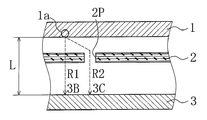
- the active material 1a in the vicinity of the pinhole (through hole) 2P is the shortest without passing through the pinhole 2P. It is preferably occluded in the Li ion storage destination 3B that faces the closest through the route R1 that goes straight at a distance.
- the active material 1a in the vicinity of the pinhole 2P is occluded in the Li ion occlusion destination 3C facing the pinhole 2P via the path R2 passing through the pinhole 2P.
- This is thought to be preferentially occluded in the Li ion occlusion destination 3C because the path R2 passing through the pinhole 2P has a lower resistance.
- the Li ion storage amount of the negative electrode active material in the Li ion storage destination 3C exceeds the limit, it is considered that an internal short circuit occurs. That is, the cause of the internal short circuit is considered to be that the distance L between the electrodes is short and the potential difference until the deposition is small.
- the active material 1a in the vicinity of the pinhole 2P should move through the path R1 passing through the pinhole 2P through the path R2 passing through the pinhole 2P, although it should move through the path R1 that goes straight through the shortest distance to the Li ion storage destination 3B. Then, it is occluded in the farther Li ion occlusion destination 3C.
- the oxide negative electrode is excellent in load characteristics and has a large specific capacity, so that the amount of electrode coating can be reduced as compared with a graphite negative electrode having the same capacity.
- an oxide of Si or Sn having a large specific capacity is likely to exert the effect of the present invention.
- the negative electrode is thinned in terms of the electrode configuration, the acceptability of Li ions is advantageous, and lithium dendride is hardly generated during charging. This point is also considered suitable for using a nonwoven fabric for the separator.
- the small-sized battery in which this evaluation test was performed had a small capacity, and even when an internal short circuit occurred as in the comparative battery R3, the amount of heat generated was small, so it could be charged relatively safely.
- the comparative battery R3 When the capacity is 780 mAh, which is 10 times the battery configuration, the surface temperature of the battery rises to 60 ° C. or more due to an internal short circuit during charging, and the risk of explosion, ignition, etc. increases. Therefore, it is considered difficult to use a nonwoven fabric for a graphite negative electrode.
- Example 3 [Second Embodiment] (Example 3) And a PVDF molybdenum dioxide MoO 2 and AB 90: 5: were mixed in NMP at a weight ratio of 5, to prepare a negative electrode mixture slurry.
- This negative electrode mixture slurry was applied to both surfaces of a Cu foil as a negative electrode current collector, then dried and rolled to obtain a negative electrode plate.
- a test battery was produced in the same manner as in the case of the inventive battery T1 in the first example except that this negative electrode plate was used.
- the test battery thus produced is hereinafter referred to as the present invention battery T3.
- Example 4 A test battery was produced in the same manner as in the case of the battery T3 of the present invention except that an Al foil was used as the negative electrode current collector.
- the test battery thus produced is hereinafter referred to as the present invention battery T4.
- Comparative Example 5 A test battery was prepared in the same manner as the battery T3 of the present invention except that a polyethylene microporous film (film thickness 20 ⁇ m, porosity 45%, air permeability 110 s / 100 cc air) was used as the separator. .
- the test battery thus produced is hereinafter referred to as comparative battery R5.
- Comparative Example 6 A test battery was prepared in the same manner as the battery T4 of the present invention except that a polyethylene microporous film (film thickness 20 ⁇ m, porosity 45%, air permeability 110 s / 100 cc air) was used as the separator. .
- the test battery thus produced is hereinafter referred to as comparative battery R6.
- an Al foil can be used as a current collector. In this respect, the cost can be further reduced by replacing the Cu foil. Moreover, since Al forms an alloy with lithium at around 0.6 V, it is possible to suppress precipitation of lithium even if the limit of the lithium storage capacity of the active material is exceeded. Therefore, it is possible to take double measures against the problem of internal short circuit due to Li dendride precipitation.
- a lithium-titanium composite oxide having a lithium ion storage / desorption potential in the vicinity of 1.5 V can be considered.
- lithium titanium composite oxide there is almost no capacity merit because it has almost the same capacity as an aqueous battery, and it is considered that it is inferior in price compared to an aqueous battery. It is considered difficult to put into practical use.
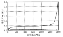
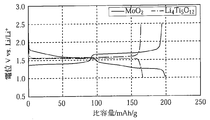
- molybdenum oxide as shown in FIG. 6, there is a merit in terms of capacity, so it can be considered that it can compete in the development of new applications.
- FIG. 6 shows a comparison per unit weight, it becomes about 2.2 times per unit volume as described above, and the effect of increasing the capacity becomes more remarkable.
- the positive electrode active material is not limited to the above lithium cobalt oxide, but is a cobalt-nickel-manganese lithium composite oxide, an aluminum-nickel-manganese lithium composite oxide, or an aluminum-nickel-cobalt lithium.
- a lithium composite oxide containing cobalt, nickel, or manganese, such as a composite oxide, or spinel type lithium manganate may be used.
- a lithium composite compound having a potential of 4 V or more is desirable for the purpose of securing energy density.
- the concentration of the supporting salt is not particularly limited, but is preferably 0.8 to 1.8 mol per liter of the electrolyte.
- the solvent species include carbonates such as propylene carbonate (PC), ⁇ -butyrolactone (GBL), ethyl methyl carbonate (EMC), dimethyl carbonate (DMC), and methyl ethyl carbonate (MEC).
- PC propylene carbonate
- GBL ⁇ -butyrolactone
- EMC ethyl methyl carbonate
- DMC dimethyl carbonate
- MEC methyl ethyl carbonate
- a solvent is preferable, and a combination of a cyclic carbonate and a chain carbonate is more preferable.
- the molybdenum oxide used in the present invention may have a plurality of structures when molybdenum is 4, 5, or 6 inclusive, but rutile molybdenum dioxide is preferable because of its high initial charge / discharge efficiency.
- molybdenum trioxide or an intermediate composition can be used.
- the initial charge / discharge efficiency is not good, it is desirable to perform Li pre-doping or the like in order to ensure the capacity. Pre-doping can be dealt with by attaching Li foil or the like.
- the present invention can be suitably applied to, for example, a drive power source application for mobile information terminals such as a mobile phone, a notebook personal computer, and a PDA, particularly an application in which an aqueous solution battery such as a nickel metal hydride battery is used.
- a drive power source application for mobile information terminals such as a mobile phone, a notebook personal computer, and a PDA
- an aqueous solution battery such as a nickel metal hydride battery is used.
Landscapes
- Chemical & Material Sciences (AREA)
- Chemical Kinetics & Catalysis (AREA)
- Electrochemistry (AREA)
- General Chemical & Material Sciences (AREA)
- Engineering & Computer Science (AREA)
- Inorganic Chemistry (AREA)
- Manufacturing & Machinery (AREA)
- Materials Engineering (AREA)
- Secondary Cells (AREA)
Abstract
内部短絡の危険性が低くて安全であり、かつ低コストで安価に作製することが可能なリチウム二次電池を提供すること。 正極と負極とセパレータと非水電解液を有するリチウム二次電池において、負極における負極活物質を、1.0Vよりも卑な電位でリチウムを吸蔵脱離する酸化物およびモリブデン酸化物のうちの少なくとも一方を含むものとし、セパレータとして不織布を用いる。不織布の厚みを、望ましくは10~25μmとする。負極活物質を、望ましくはSiおよびSnのうち少なくとも1つを含む酸化物を含有してなるものとする。負極活物質を望ましくはモリブデンを含む酸化物とし、負極集電体を望ましくはAl箔とする。
Description
本発明は、リチウムイオン電池をはじめとする非水電解質電池の改良に関し、特に安価で容量および信頼性の高い電池構造に関するものである。
近年、携帯電話、ノートパソコン、PDAなどの移動情報端末の小型・軽量化が急速に進展しており、その駆動電源として、電池は更なる高容量化が要求されている。二次電池の中でも高エネルギー密度であるLiイオン電池の高容量化は年々進んでおり、特に携帯電話のカラー機能、動画機能、通信機能、音楽機能等の高機能化に伴い、更に消費電力は増大する傾向にあり、長時間再生や出力改善等のための高容量化および高性能化が強く望まれている。その一方で、新規用途への展開も進められている。
非水電解質電池は、電解液の種類を変更することによって様々な電位を選択でき、水の電気分解の電位に左右される水溶液系の電池よりも活物質の組み合わせの選択肢が多い。
リチウムイオン電池は、開発当初からコバルト酸リチウム正極と黒鉛負極との組み合わせが主流であるが、正極活物質としては、NiCoMnの3元系酸化物、スピネル型マンガン酸リチウムなどの4V系材料や、高出力用に開発されたオリビン型燐酸鉄リチウム、高容量向けのLi過剰型酸化物などが挙げられる。また、負極活物質としては、黒鉛やSiやSn等が挙げられる。
このようにリチウムイオン電池は、各種材料の組み合わせで特徴づけを行うことで、新規用途への展開が検討されている。この中で、新しい電池系との比較対象となるのは、コバルト酸リチウム/黒鉛のリチウムイオン電池や、置き換えが進んでいるニッケル水素電池、ニカド電池、鉛蓄電池である。性能面では前者と、価格面では後者との比較となり、高性能で安価なリチウムイオン電池の開発が必要とされている。
前述のような背景の中、セパレータは、正負極の隔離の他に、異常時の充放電反応に伴うLiデンドライドの析出を防止する等の安全機能が必要であることから、孔構造の複雑なポリオレフィン系の微多孔膜が用いられる。しかし、電池構成の中でもセパレータの占めるコスト割合は高く、セパレータを如何に変更できるかが、低コスト化に際しての大きな課題である。
ここで、メモリーバックアップ用途などのコイン電池では、非水電解質電池でありながら、セパレータとして、微多孔膜ではなく、ガラス繊維や樹脂繊維等を材質とする不織布などの簡易なセパレータが用いられている。コイン電池の場合、使用する電流が最大で0.1C程度と小さく、また、民生用の電池におけるセパレータが20μm前後であるのに比べてセパレータが最薄でも60μm以上と厚いことから、複雑な孔構造を有する微多孔膜をセパレータとして用いずともLiデンドライドの析出は起こり難く、不織布などの簡易で安価なセパレータを使用することが出来る。
一方、民生用のリチウムイオン電池(コバルト酸リチウム/黒鉛)のセパレータに不織布を用いた場合、上述の20μm前後の厚みでは孔構造の複雑さの度合いが全く不十分であった。つまり、不織布にピンホールがあると、充電中にLiデンドライドが生じ、電圧印加時は微小内部短絡が発生することになって、正常な充電が出来ないという課題があった(充放電効率の低下及び短絡による発熱)。これは、黒鉛のリチウムイオンの吸蔵・脱離の電位が0.1VとLi析出電位である0.0Vに近いことに起因するものと推測される。また、通常使用電流値が1C程度であることも要因のひとつと推測される。
したがって、本発明は、内部短絡の危険性が低くて安全であり、かつ低コストで安価に作製することが可能なリチウム二次電池を提供することを目的とする。
上記目的を達成する為に、本発明に係るリチウム二次電池は、正極と負極とセパレータと非水電解液を有するリチウム二次電池において、前記負極における負極活物質が、1.0Vよりも卑な電位でリチウムを吸蔵脱離する酸化物およびモリブデン酸化物のうちの少なくとも一方を含み、前記セパレータとして不織布が用いられていることを特徴とする。
上記本発明の構成によれば、負極活物質に1.0Vよりも卑な電位でリチウムを吸蔵脱離する酸化物およびモリブデン酸化物のうちの少なくとも一方を用いることで、セパレータを不織布にすることが可能となり、ポリオレフィン系の微多孔膜よりも安価に電池を作製することが出来る。
酸化物負極は、リチウムを吸蔵脱離する電位が、例えばSiの場合で約0.4Vと、黒鉛負極の0.1Vに比べて高く、Li析出までの電位差を大きくすることができる。このため、Liデンドライド析出の問題を回避することができ、充電時の内部短絡の危険性を低くすることができる。このため、高価なポリオレフィン系の微多孔膜を使用しなくても、貫通孔が存在するような薄い不織布でもセパレータに使用できる。
ただし、酸化物負極であっても、リチウムチタン複合酸化物などは、リチウムを吸蔵脱離する電位が1.55Vと高く、0.1V程度の黒鉛と比べてエネルギー密度的に不利になる。例えば、コバルト酸リチウムを正極に用いた場合、黒鉛では通常4.2V(4.3-0.1)の電位差があるのに対して、リチウムチタン複合酸化物では2.75V(4.3-1.55)しかない。この分、エネルギー密度(Wh/l)は低下することになり、ニッケル水素電池などの水溶液系電池と比べ、リチウムイオン電池を用いるメリットが小さい。
これに対して、負極活物質に1.0Vよりも卑な電位でリチウムを吸蔵脱離する酸化物、例えば特に後述するような、SiおよびSnのうち少なくとも1つを含む酸化物を用いることで、電位によるデメリットを低減できる。また、これらの化合物は比容量も大きい為、黒鉛負極に対してもエネルギー密度的なデメリットを軽減できる。
これに対して、負極活物質に1.0Vよりも卑な電位でリチウムを吸蔵脱離する酸化物、例えば特に後述するような、SiおよびSnのうち少なくとも1つを含む酸化物を用いることで、電位によるデメリットを低減できる。また、これらの化合物は比容量も大きい為、黒鉛負極に対してもエネルギー密度的なデメリットを軽減できる。
また、負極活物質にモリブデンを含む酸化物を用いることでリチウムチタン複合酸化物に比べて容量を増大することができ、ニッケル水素電池等の水溶液系電池と比べて、容量的なメリットを見出すことができる。なお、モリブデン酸化物のリチウムイオン吸蔵・脱離の電位はおよそ1.5Vと、リチウムチタン複合酸化物の1.55Vと近い程度に高いが、リチウムチタン複合酸化物の理論密度は3.5g/cc、比容量は175mAh/gであり、単位体積あたり613mAh/ccとなるのに対して、モリブデン酸化物の理論密度は6.4g/cc、比容量は210mAh/gであり、単位体積あたり1344mAh/ccである。したがって、モリブデン酸化物の単位体積あたりの比容量は、リチウムチタン複合酸化物の単位体積あたりの比容量のおよそ2.2倍であるため、モリブデン酸化物を用いるほうが、リチウムチタン複合酸化物を用いるよりも、容量面でのメリットが大きい。
前記不織布の厚みが10-25μm、より好適には16-20μmであることが望ましい。
民生用の電池で用いられるセパレータの場合には、エネルギー密度を低く抑えておく必要から、前述のコイン電池で用いられている不織布製のセパレータのように60μm以上のセパレータを用いることは好ましくなく、上述のような厚み10-25μm程度の範囲内の薄いものを用いることが好ましい。ここで、従来の黒鉛負極ではLiデンドライドが生じて内部短絡が発生するという問題があったが、酸化物負極を用いることで、不織布の厚みが10-25μmの範囲内であっても、Liデンドライド析出の問題を回避することができる。
前記負極活物質が、W、SiおよびSnのうち少なくとも1つを含む酸化物を含有してなるものであることが望ましく、特に、SiおよびSnのうち少なくとも1つを含む酸化物を含有してなるものであることが望ましい。
酸化物負極は、負荷特性に優れ、また、比容量が大きい。このため、酸化物負極を用いた負極は、同一容量の黒鉛負極と比較して、電極塗布量を少なく出来る。特に比容量の大きいSiやSnの酸化物は、本発明の効果が発揮し易い。このため、電極構成の面でも負極が薄くなる分、Liイオンの受入れ性が有利になり、充電中にリチウムデンドライドは発生し難くなる。この点もセパレータに不織布を用いることに適していると考えられる。
前記負極活物質がモリブデンを含む酸化物であり、負極集電体がAl箔であることが望ましい。
モリブデン酸化物は、前述の通りリチウムイオン吸蔵・脱離の電位が高い。このためモリブデン酸化物を負極活物質として用いた場合には、集電体にCu箔ではなく、より安価なAl箔を使用することもできるため、さらにコストを低減することができる。また、Li-Alの合金化電位が0.6Vであることから、Liデンドライドの成長を更に抑制できる。
なお、負極活物質としては、1.0Vよりも卑な電位でリチウムを吸蔵脱離する酸化物およびモリブデン酸化物のうち、いずれか1種の酸化物を単独で用いるほうが、当該酸化物による作用をより効果的に発揮できて望ましいが、これらのうちの複数種の酸化物を混合して用いてもよい。また、これらの酸化物以外の負極活物質をさらに含有していてもよいが、黒鉛は含有しないものとすることが望ましい。負極活物質が黒鉛を含有していると、リチウムイオン吸蔵・脱離の電位が0.0Vに近づくこととなってリチウムデンドライドが発生しやすくなる惧れがある。
本発明のリチウム二次電池は、負極活物質として特定の酸化物を用いることによって、Liデンドライドの析出による内部短絡の問題を回避しながら、セパレータとして高価なポリオレフィン系の微多孔膜にかえて安価な不織布を用いることを可能としたものである。したがって本発明により、安全性に優れるとともに安価に作製することが可能なリチウム二次電池を得ることができる。
以下、本発明を図面を参照しながら更に詳細に説明するが、本発明は以下の最良の形態になんら限定されるものではなく、その趣旨を変更しない範囲において適宜変更して実施することが可能なものである。
〔正極の作製〕
正極活物質であるコバルト酸リチウムLiCoO2と、炭素導電剤であるアセチレンブラック(AB)と、バインダーであるポリフッ化ビニリデン(PVDF)とを95:2.5:2.5の質量比でN-メチル-2-ピロリドン(NMP)を希釈溶媒として、プライミクス社製コンビミックスを用いて攪拌し、正極合剤スラリーを調製した。この正極合剤スラリーを、正極集電体としてのアルミニウム箔の両面に塗着し、乾燥後圧延して正極板とした。
正極活物質であるコバルト酸リチウムLiCoO2と、炭素導電剤であるアセチレンブラック(AB)と、バインダーであるポリフッ化ビニリデン(PVDF)とを95:2.5:2.5の質量比でN-メチル-2-ピロリドン(NMP)を希釈溶媒として、プライミクス社製コンビミックスを用いて攪拌し、正極合剤スラリーを調製した。この正極合剤スラリーを、正極集電体としてのアルミニウム箔の両面に塗着し、乾燥後圧延して正極板とした。
〔負極の作製〕
二酸化シリコンSiO2とABとポリイミド(PI)とを89:4:7の質量比でNMP中にて混合し、負極合剤スラリーを調製した。この負極合剤スラリーを、負極集電体としての銅箔の両面に塗着した後、乾燥後圧延して負極板とした。この後、Ar雰囲気で400℃で10時間熱処理を行い、イミド化処理を行った。
二酸化シリコンSiO2とABとポリイミド(PI)とを89:4:7の質量比でNMP中にて混合し、負極合剤スラリーを調製した。この負極合剤スラリーを、負極集電体としての銅箔の両面に塗着した後、乾燥後圧延して負極板とした。この後、Ar雰囲気で400℃で10時間熱処理を行い、イミド化処理を行った。
〔非水電解液の調製〕
エチレンカーボネート(EC)とジエチルカーボネート(DEC)とが体積比で30:70の割合で混合された混合溶媒に、LiPF6を1.0mol/lの割合で溶解・混合して、電解液を得た。
エチレンカーボネート(EC)とジエチルカーボネート(DEC)とが体積比で30:70の割合で混合された混合溶媒に、LiPF6を1.0mol/lの割合で溶解・混合して、電解液を得た。
〔電池の組立〕
正極板および負極板のそれぞれにリード端子を取り付け、セパレータ(ポリプロピレン製不織布:膜厚20μm、空孔率70%、透気度1s/100cc air)を介して渦巻状に巻き取ったものをプレスして扁平状に押し潰した電極体を、電池外装体としてのアルミニウムラミネートを用いたものに入れて電解液を注液し、封止して試験用電池とした。尚、本試作電池の設計容量は78mAhである。
正極板および負極板のそれぞれにリード端子を取り付け、セパレータ(ポリプロピレン製不織布:膜厚20μm、空孔率70%、透気度1s/100cc air)を介して渦巻状に巻き取ったものをプレスして扁平状に押し潰した電極体を、電池外装体としてのアルミニウムラミネートを用いたものに入れて電解液を注液し、封止して試験用電池とした。尚、本試作電池の設計容量は78mAhである。
〔第1実施例〕
(実施例1)
実施例の試験用電池としては、上記発明を実施する為の形態で説明した試験用電池と同様に作製したものを用いた。
このようにして作製した試験用電池を、以下、本発明電池T1と称す。
(実施例1)
実施例の試験用電池としては、上記発明を実施する為の形態で説明した試験用電池と同様に作製したものを用いた。
このようにして作製した試験用電池を、以下、本発明電池T1と称す。
(実施例2)
負極活物質に酸化タングステンWO2を用い、負極合剤組成を質量比でWO2:AB:PVDF=90:5:5とした点、ならびに熱処理工程を加えないようにした点以外は、前記本発明電池T1の場合と同様にして試験用電池を作製した。
このようにして作製した試験用電池を、以下、本発明電池T2と称す。
負極活物質に酸化タングステンWO2を用い、負極合剤組成を質量比でWO2:AB:PVDF=90:5:5とした点、ならびに熱処理工程を加えないようにした点以外は、前記本発明電池T1の場合と同様にして試験用電池を作製した。
このようにして作製した試験用電池を、以下、本発明電池T2と称す。
(比較例1)
セパレータとしてポリエチレン製微多孔膜(膜厚20μm、空孔率45%、透気度110s/100cc air)を用いた点以外は、前記本発明電池T1の場合と同様にして試験用電池を作製した。
このようにして作製した試験用電池を、以下、比較電池R1と称す。
セパレータとしてポリエチレン製微多孔膜(膜厚20μm、空孔率45%、透気度110s/100cc air)を用いた点以外は、前記本発明電池T1の場合と同様にして試験用電池を作製した。
このようにして作製した試験用電池を、以下、比較電池R1と称す。
(比較例2)
セパレータとしてポリエチレン製微多孔膜(膜厚20μm、空孔率45%、透気度110s/100cc air)を用いた点以外は、前記本発明電池T2の場合と同様にして試験用電池を作製した。
このようにして作製した試験用電池を、以下、比較電池R2と称す。
セパレータとしてポリエチレン製微多孔膜(膜厚20μm、空孔率45%、透気度110s/100cc air)を用いた点以外は、前記本発明電池T2の場合と同様にして試験用電池を作製した。
このようにして作製した試験用電池を、以下、比較電池R2と称す。
(比較例3)
負極活物質として黒鉛(組成 黒鉛:カルボキシメチルセルロースナトリウム(CMC):スチレン・ブタジエンゴム(SBR)=98:1:1)を用いた点、ならびに熱処理工程を加えないようにした点以外は、前記本発明電池T1の場合と同様にして試験用電池を作製した。
このようにして作製した試験用電池を、以下、比較電池R3と称す。
負極活物質として黒鉛(組成 黒鉛:カルボキシメチルセルロースナトリウム(CMC):スチレン・ブタジエンゴム(SBR)=98:1:1)を用いた点、ならびに熱処理工程を加えないようにした点以外は、前記本発明電池T1の場合と同様にして試験用電池を作製した。
このようにして作製した試験用電池を、以下、比較電池R3と称す。
(比較例4)
負極活物質として黒鉛(組成 黒鉛:カルボキシメチルセルロースナトリウム(CMC):スチレン・ブタジエンゴム(SBR)=98:1:1)を用いた点、ならびに熱処理工程を加えないようにした点以外は、前記比較電池R1の場合と同様にして試験用電池を作製した。
このようにして作製した試験用電池を、以下、比較電池R4と称す。
負極活物質として黒鉛(組成 黒鉛:カルボキシメチルセルロースナトリウム(CMC):スチレン・ブタジエンゴム(SBR)=98:1:1)を用いた点、ならびに熱処理工程を加えないようにした点以外は、前記比較電池R1の場合と同様にして試験用電池を作製した。
このようにして作製した試験用電池を、以下、比較電池R4と称す。
〔試験用電池の評価試験〕
○充電試験
1.0It(75mA)の電流で4.2V(WO2負極の場合3.7V)まで定電流充電を行い、4.2V(WO2負極の場合3.7V)の定電圧で電流1/20It(3.75mA)になるまで充電した。通常、本条件では1.5時間程度で充電は完了する。本試験については、最大の充電時間を3時間と限定して充電を行なった。
○放電試験
1.0It(75mA)の電流で2.5V(WO2負極の場合1.5V)まで定電流放電を行った。
○休止
充電試験と放電試験との間隔は10分とした。
○充電試験
1.0It(75mA)の電流で4.2V(WO2負極の場合3.7V)まで定電流充電を行い、4.2V(WO2負極の場合3.7V)の定電圧で電流1/20It(3.75mA)になるまで充電した。通常、本条件では1.5時間程度で充電は完了する。本試験については、最大の充電時間を3時間と限定して充電を行なった。
○放電試験
1.0It(75mA)の電流で2.5V(WO2負極の場合1.5V)まで定電流放電を行った。
○休止
充電試験と放電試験との間隔は10分とした。
〔25℃サイクル試験〕
上記本発明電池T1、T2および比較電池R1~R4を用いて、上記充放電条件で25℃雰囲気における1.0It充放電サイクルを実施し、下記の式に従って充放電の効率を算出した。
充放電効率(%)=放電容量/充電容量×100
表1に、上記本発明電池T1、T2および比較電池R1~R4の初回充放電効率を示す。
上記本発明電池T1、T2および比較電池R1~R4を用いて、上記充放電条件で25℃雰囲気における1.0It充放電サイクルを実施し、下記の式に従って充放電の効率を算出した。
充放電効率(%)=放電容量/充電容量×100
表1に、上記本発明電池T1、T2および比較電池R1~R4の初回充放電効率を示す。

〔評価試験の結果〕
上記本発明電池T1、T2と、セパレータとしてポリエチレン製微多孔膜を用いた比較電池R1、R2、R4とを比較した場合、充放電効率はほぼ同等であった。つまり、材料固有の性能からも妥当な結果が得られ、本発明電池T1、T2の構成で十分にリチウムイオン電池として機能することがわかった。
上記本発明電池T1、T2と、セパレータとしてポリエチレン製微多孔膜を用いた比較電池R1、R2、R4とを比較した場合、充放電効率はほぼ同等であった。つまり、材料固有の性能からも妥当な結果が得られ、本発明電池T1、T2の構成で十分にリチウムイオン電池として機能することがわかった。
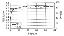
一方、負極として黒鉛を、セパレータとして不織布をそれぞれ用いた比較電池R3では、図1に示すように、最大充電時間の3時間が経過しても電流が下がらないままであり、この時点で充電を終了した。これは、不織布の製法に特有のピンホールの存在により、充電中に内部短絡が発生したため、電流が下がらないままであったと考えられる。この結果、充電は完了していないため、充放電効率は47.4%と低かった。
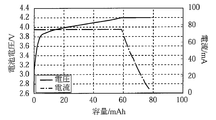
他方、負極として黒鉛を、セパレータとしてポリエチレン製微多孔膜をそれぞれ用いた比較電池R4では、図2に示すように、問題なく充放電を完了することが可能であった。
他方、負極として黒鉛を、セパレータとしてポリエチレン製微多孔膜をそれぞれ用いた比較電池R4では、図2に示すように、問題なく充放電を完了することが可能であった。
〔考察〕
上記比較電池R3でみられた内部短絡の発生は、黒鉛がリチウムイオンを吸蔵脱離する電位が0.1Vであり、Liの析出電位である0Vとのマージンが小さい為と考えられる。ここで、Liデンドライドの析出による内部短絡を抑制する為には、正負極間の抵抗を一定以上確保し、短絡し難い構造を作ることが必要であり、セパレータとしては、微多孔膜のように、連続貫通孔のない構造を有するものとすることが効果的であると考えられる。しかしながら、不織布の場合、複数の繊維を重ねてカレンダー処理しているに過ぎないため、ピンホールのような貫通孔が生じ易い。したがって、比較電池R3では貫通孔が影響して内部短絡が発生したものと考えられる。さらに、リチウムイオン電池の場合、高い出力密度を得る為には、電極面積を大きくする必要があり、これに伴い、セパレータの面積も増加するため、それだけ内部短絡の発生し易い状況が形成されることとなる。
上記比較電池R3でみられた内部短絡の発生は、黒鉛がリチウムイオンを吸蔵脱離する電位が0.1Vであり、Liの析出電位である0Vとのマージンが小さい為と考えられる。ここで、Liデンドライドの析出による内部短絡を抑制する為には、正負極間の抵抗を一定以上確保し、短絡し難い構造を作ることが必要であり、セパレータとしては、微多孔膜のように、連続貫通孔のない構造を有するものとすることが効果的であると考えられる。しかしながら、不織布の場合、複数の繊維を重ねてカレンダー処理しているに過ぎないため、ピンホールのような貫通孔が生じ易い。したがって、比較電池R3では貫通孔が影響して内部短絡が発生したものと考えられる。さらに、リチウムイオン電池の場合、高い出力密度を得る為には、電極面積を大きくする必要があり、これに伴い、セパレータの面積も増加するため、それだけ内部短絡の発生し易い状況が形成されることとなる。
上記内部短絡が生じる経緯の詳細は不明であるが、発明者による検討結果を図5を用いて説明する。例えば図5に示すように、正極1と負極3とが不織布セパレータ2を介して対向配置された構成において、ピンホール(貫通孔)2P近傍の活物質1aは、ピンホール2Pを通ることなく最短距離で直行する経路R1を経由して、直近に対向するLiイオン吸蔵先3Bに吸蔵されることが好ましい。しかしながら、ピンホール2Pの存在により、ピンホール2P近傍の活物質1aは、ピンホール2Pを通る経路R2を経由して、該ピンホール2Pに対向するLiイオン吸蔵先3Cに吸蔵される。これは、ピンホール2Pを通る経路R2を移動する方が低抵抗であるため、優先してLiイオン吸蔵先3Cに吸蔵されるものと考えられる。そして、Liイオン吸蔵先3Cにおける負極活物質のLiイオン吸蔵量が限度を超えると、内部短絡が発生するものと考えられる。すなわち、内部短絡発生の要因は、両極間距離Lが短く、析出に至るまでの電位差が小さいためであると考えられる。つまり、ピンホール2P近傍の活物質1aは、最短距離で直行する経路R1を通って直近に対向するLiイオン吸蔵先3Bに移動すべきであるのに、ピンホール2Pを経由する経路R2を通って、より遠いLiイオン吸蔵先3Cに吸蔵される。
これに対し、酸化物負極は負荷特性に優れ、また、比容量が大きいことから、同一容量の黒鉛負極と比較して電極塗布量を少なく出来る。特に比容量の大きいSiやSnの酸化物は、本発明の効果が発揮し易い。このため、電極構成の面でも負極が薄くなる分、Liイオンの受入れ性は有利になり、充電中にリチウムデンドライドは発生し難い。この点もセパレータに不織布を用いることに適していると考えられる。
また、本評価試験を実施した小型サイズの電池では容量が小さく、比較電池R3のように内部短絡が生じた場合でも発熱量は小さい為、比較的安全に充電できたが、例えば、比較電池R3の電池構成で容量を10倍の780mAhとした場合、充電中の内部短絡により電池の表面温度は60℃以上に上昇し、破裂や発火等の危険性が高くなる。従って黒鉛負極では不織布の使用は困難であると考えられる。
以上のことから、酸化物を負極活物質として用いれば、不織布をセパレータに用いることができ、これにより材料コストを安価にすることが可能となるということができる。
〔第2実施例〕
(実施例3)
二酸化モリブデンMoO2とABとPVDFとを90:5:5の質量比でNMP中にて混合し、負極合剤スラリーを調製した。この負極合剤スラリーを、負極集電体としてのCu箔の両面に塗着した後、乾燥後圧延して負極板とした。この負極板を用いるようにした点以外は、前記第1実施例における本発明電池T1の場合と同様にして試験用電池を作製した。
このようにして作製した試験用電池を、以下、本発明電池T3と称す。
(実施例3)
二酸化モリブデンMoO2とABとPVDFとを90:5:5の質量比でNMP中にて混合し、負極合剤スラリーを調製した。この負極合剤スラリーを、負極集電体としてのCu箔の両面に塗着した後、乾燥後圧延して負極板とした。この負極板を用いるようにした点以外は、前記第1実施例における本発明電池T1の場合と同様にして試験用電池を作製した。
このようにして作製した試験用電池を、以下、本発明電池T3と称す。
(実施例4)
負極集電体としてAl箔を用いるようにした点以外は、前記本発明電池T3の場合と同様にして試験用電池を作製した。
このようにして作製した試験用電池を、以下、本発明電池T4と称す。
負極集電体としてAl箔を用いるようにした点以外は、前記本発明電池T3の場合と同様にして試験用電池を作製した。
このようにして作製した試験用電池を、以下、本発明電池T4と称す。
(比較例5)
セパレータとしてポリエチレン製微多孔膜(膜厚20μm、空孔率45%、透気度110s/100cc air)を用いた点以外は、前記本発明電池T3の場合と同様にして試験用電池を作製した。
このようにして作製した試験用電池を、以下、比較電池R5と称す。
セパレータとしてポリエチレン製微多孔膜(膜厚20μm、空孔率45%、透気度110s/100cc air)を用いた点以外は、前記本発明電池T3の場合と同様にして試験用電池を作製した。
このようにして作製した試験用電池を、以下、比較電池R5と称す。
(比較例6)
セパレータとしてポリエチレン製微多孔膜(膜厚20μm、空孔率45%、透気度110s/100cc air)を用いた点以外は、前記本発明電池T4の場合と同様にして試験用電池を作製した。
このようにして作製した試験用電池を、以下、比較電池R6と称す。
セパレータとしてポリエチレン製微多孔膜(膜厚20μm、空孔率45%、透気度110s/100cc air)を用いた点以外は、前記本発明電池T4の場合と同様にして試験用電池を作製した。
このようにして作製した試験用電池を、以下、比較電池R6と称す。
〔試験用電池の評価〕
○充電試験
1.0It(75mA)の電流で3.3Vまで定電流充電を行い、3.3Vの定電圧で電流It/20(3.75mA)になるまで充電した。通常、本条件では1.5時間程度で充電は完了する。本試験については、最大の充電時間を3時間と限定して充電を行なった。
○放電試験
1.0It(75mA)の電流で1.0Vまで定電流放電を行った。
○休止
充電試験と放電試験との間隔は10分とした。
○充電試験
1.0It(75mA)の電流で3.3Vまで定電流充電を行い、3.3Vの定電圧で電流It/20(3.75mA)になるまで充電した。通常、本条件では1.5時間程度で充電は完了する。本試験については、最大の充電時間を3時間と限定して充電を行なった。
○放電試験
1.0It(75mA)の電流で1.0Vまで定電流放電を行った。
○休止
充電試験と放電試験との間隔は10分とした。
〔25℃サイクル試験〕
上記本発明電池T3、T4および比較電池R5~R6を用いて、上記充放電条件で25℃雰囲気における1.0It充放電サイクルを実施し、下記の式に従って充放電の効率を算出した。
充放電効率(%)=放電容量/充電容量×100
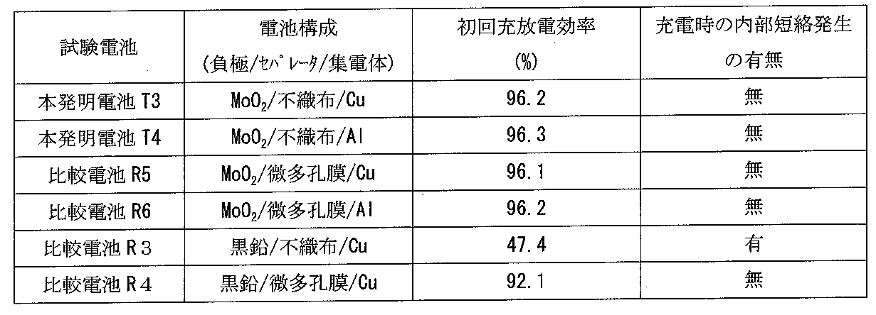
表2に、上記本発明電池T3、T4および比較電池R3~R6の初回充放電効率を示す。
上記本発明電池T3、T4および比較電池R5~R6を用いて、上記充放電条件で25℃雰囲気における1.0It充放電サイクルを実施し、下記の式に従って充放電の効率を算出した。
充放電効率(%)=放電容量/充電容量×100
表2に、上記本発明電池T3、T4および比較電池R3~R6の初回充放電効率を示す。
〔評価試験の結果〕
上記本発明電池T3、T4と、セパレータとしてポリエチレン製微多孔膜を用いた比較電池R4、R5、R6とを比較した場合、充放電効率はほぼ同等であった。つまり、材料固有の性能からも妥当な結果が得られ、前述の第1実施例における本発明電池T1、T2の場合と同様に、本発明電池T3、T4の構成で十分にリチウムイオン電池として機能することがわかった。
上記本発明電池T3、T4と、セパレータとしてポリエチレン製微多孔膜を用いた比較電池R4、R5、R6とを比較した場合、充放電効率はほぼ同等であった。つまり、材料固有の性能からも妥当な結果が得られ、前述の第1実施例における本発明電池T1、T2の場合と同様に、本発明電池T3、T4の構成で十分にリチウムイオン電池として機能することがわかった。
〔考察〕
負極として黒鉛を、セパレータとして不織布をそれぞれ用いる(比較電池R3)と内部短絡が生じる経緯については、前述の第1実施例における考察で述べた通りである。一方、上記本発明電池T3、T4で負極活物質として用いている二酸化モリブデンMoO2は酸化物であるから、これがセパレータに不織布を用いることに適しているのも、前述の第1実施例における考察で述べた酸化物の場合と同様である。従って、モリブデン酸化物を負極活物質として用いることによっても、不織布をセパレータに用いることができ、これにより材料コストを安価にすることが可能となる。また、モリブデン酸化物がリチウムイオンを吸蔵脱離する電位が1.5Vと高いことから、Al箔を集電体に用いることができる。この点でも、Cu箔からの置き換えにより、さらに安価にすることができる。また、Alはリチウムと0.6V付近で合金化するため、万が一活物質のリチウム吸蔵量の限度を超えたとしても、リチウムが析出することを抑制できる。したがってLiデンドライドの析出による内部短絡の問題に対して二重の対策を講じることができることとなる。
負極として黒鉛を、セパレータとして不織布をそれぞれ用いる(比較電池R3)と内部短絡が生じる経緯については、前述の第1実施例における考察で述べた通りである。一方、上記本発明電池T3、T4で負極活物質として用いている二酸化モリブデンMoO2は酸化物であるから、これがセパレータに不織布を用いることに適しているのも、前述の第1実施例における考察で述べた酸化物の場合と同様である。従って、モリブデン酸化物を負極活物質として用いることによっても、不織布をセパレータに用いることができ、これにより材料コストを安価にすることが可能となる。また、モリブデン酸化物がリチウムイオンを吸蔵脱離する電位が1.5Vと高いことから、Al箔を集電体に用いることができる。この点でも、Cu箔からの置き換えにより、さらに安価にすることができる。また、Alはリチウムと0.6V付近で合金化するため、万が一活物質のリチウム吸蔵量の限度を超えたとしても、リチウムが析出することを抑制できる。したがってLiデンドライドの析出による内部短絡の問題に対して二重の対策を講じることができることとなる。
モリブデン酸化物と同様の機能を発現する負極活物質としては、1.5V付近にリチウムイオンの吸蔵脱離の電位を有するリチウムチタン複合酸化物が考えられる。しかしながら前述の通り、リチウムチタン複合酸化物を用いた場合は、水溶液系の電池とほぼ同一の容量となるため容量メリットは殆ど無く、水溶液系の電池よりも価格面で劣ると考えられることから、実用化し難いと考えられる。これに対して、モリブデン酸化物を用いた場合は、図6に示すように、容量面でもメリットが出せることから、新規用途展開においても競合できると考えられる。図6は単位重量あたりの比較になるが、単位体積あたりでは前述したようにおよそ2.2倍となり、容量増大の効果はより顕著になる。
〔その他の事項〕
(1)正極活物質としては、上記コバルト酸リチウムに限定されるものではなく、コバルト-ニッケル-マンガンのリチウム複合酸化物、アルミニウム-ニッケル-マンガンのリチウム複合酸化物、アルミニウム-ニッケル-コバルトのリチウム複合酸化物等のコバルト、ニッケル或いはマンガンを含むリチウム複合酸化物や、スピネル型マンガン酸リチウム等でも構わない。その他の正極活物質も使用できるが、エネルギー密度の確保の目的からすれば、4V以上の電位を有するリチウム複合化合物が望ましい。
(1)正極活物質としては、上記コバルト酸リチウムに限定されるものではなく、コバルト-ニッケル-マンガンのリチウム複合酸化物、アルミニウム-ニッケル-マンガンのリチウム複合酸化物、アルミニウム-ニッケル-コバルトのリチウム複合酸化物等のコバルト、ニッケル或いはマンガンを含むリチウム複合酸化物や、スピネル型マンガン酸リチウム等でも構わない。その他の正極活物質も使用できるが、エネルギー密度の確保の目的からすれば、4V以上の電位を有するリチウム複合化合物が望ましい。
(2)電解液としても特に本実施例で示したものに限定されるものではなく、リチウム塩としては例えばLiBF4、LiPF6、LiN(SO2CF3)2,LiN(SO2C2F5)2,LiPF6―x(CnF2n+1)x[但し、1<x<6、n=1又は2]等が挙げられ、これらの1種もしくは2種以上を混合して使用できる。支持塩の濃度は特に限定されないが、電解液1リットル当り0.8~1.8モルが望ましい。また、溶媒種としては上記ECやDEC以外にも、プロピレンカーボネート(PC)、γ-ブチロラクトン(GBL)、エチルメチルカーボネート(EMC)、ジメチルカーボネート(DMC)、メチルエチルカーボネート(MEC)等のカーボネート系溶媒が好ましく、更に好ましくは環状カーボネートと鎖状カーボネートの組合せが望ましい。
(3)本発明に用いられるモリブデン酸化物は、モリブデンが4, 5, 6価をとることで複数の構造が考えられるが、ルチル型の二酸化モリブデンが初回の充放電効率が高く好適である。他に三酸化モリブデンや、中間組成のものも用いることができるが、初回の充放電効率が良好でないため、容量を確保する為にはLiのプリドープなどを行うことが望ましい。プリドープはLi箔を貼り付けるなどして対応することができる。
本発明は、例えば携帯電話、ノートパソコン、PDA等の移動情報端末の駆動電源用途、特にニッケル水素電池などの水溶液電池が使用される用途に好適に適用することができる。
Claims (7)
- 正極と負極とセパレータと非水電解液を有するリチウム二次電池において、
前記負極における負極活物質が、1.0Vよりも卑な電位でリチウムを吸蔵脱離する酸化物およびモリブデン酸化物のうちの少なくとも一方を含み、前記セパレータとして不織布が用いられていることを特徴とするリチウム二次電池。 - 前記不織布の厚みが10~25μmである、請求項1に記載のリチウム二次電池。
- 前記不織布の厚みが16~20μmである、請求項2に記載のリチウム二次電池。
- 前記負極における負極活物質が、1.0Vよりも卑な電位でリチウムを吸蔵脱離する酸化物およびモリブデン酸化物のうち、いずれか1種の酸化物を単独で用いたものである、請求項1に記載のリチウム二次電池。
- 前記負極活物質が、W、SiおよびSnのうち少なくとも1つを含む酸化物を含有してなるものである、請求項1に記載のリチウム二次電池。
- 前記負極活物質が、SiおよびSnのうち少なくとも1つを含む酸化物を含有してなるものである、請求項5に記載のリチウム二次電池。
- 前記負極活物質がモリブデンを含む酸化物であり、前記負極の負極集電体がAl箔である、請求項1に記載のリチウム二次電池。
Applications Claiming Priority (2)
| Application Number | Priority Date | Filing Date | Title |
|---|---|---|---|
| JP2010-045802 | 2010-03-02 | ||
| JP2010045802 | 2010-03-02 |
Publications (1)
| Publication Number | Publication Date |
|---|---|
| WO2011108455A1 true WO2011108455A1 (ja) | 2011-09-09 |
Family
ID=44542108
Family Applications (1)
| Application Number | Title | Priority Date | Filing Date |
|---|---|---|---|
| PCT/JP2011/054300 Ceased WO2011108455A1 (ja) | 2010-03-02 | 2011-02-25 | リチウム二次電池 |
Country Status (1)
| Country | Link |
|---|---|
| WO (1) | WO2011108455A1 (ja) |
Citations (6)
| Publication number | Priority date | Publication date | Assignee | Title |
|---|---|---|---|---|
| JP2002343427A (ja) * | 2001-05-14 | 2002-11-29 | Yuasa Corp | 非水電解質リチウム二次電池 |
| JP2003323893A (ja) * | 2002-03-01 | 2003-11-14 | Matsushita Electric Ind Co Ltd | 正極活物質、その製造方法および非水電解質二次電池 |
| JP2007227358A (ja) * | 2006-01-24 | 2007-09-06 | Sanyo Electric Co Ltd | 非水電解質二次電池 |
| JP2007273143A (ja) * | 2006-03-30 | 2007-10-18 | Toshiba Corp | 非水電解質電池、電池パック及び自動車 |
| JP2008198593A (ja) * | 2007-01-16 | 2008-08-28 | Sanyo Electric Co Ltd | 非水電解質二次電池及びその製造方法 |
| JP2009081048A (ja) * | 2007-09-26 | 2009-04-16 | Toshiba Corp | 二次電池、電池パック及び車 |
-
2011
- 2011-02-25 WO PCT/JP2011/054300 patent/WO2011108455A1/ja not_active Ceased
Patent Citations (6)
| Publication number | Priority date | Publication date | Assignee | Title |
|---|---|---|---|---|
| JP2002343427A (ja) * | 2001-05-14 | 2002-11-29 | Yuasa Corp | 非水電解質リチウム二次電池 |
| JP2003323893A (ja) * | 2002-03-01 | 2003-11-14 | Matsushita Electric Ind Co Ltd | 正極活物質、その製造方法および非水電解質二次電池 |
| JP2007227358A (ja) * | 2006-01-24 | 2007-09-06 | Sanyo Electric Co Ltd | 非水電解質二次電池 |
| JP2007273143A (ja) * | 2006-03-30 | 2007-10-18 | Toshiba Corp | 非水電解質電池、電池パック及び自動車 |
| JP2008198593A (ja) * | 2007-01-16 | 2008-08-28 | Sanyo Electric Co Ltd | 非水電解質二次電池及びその製造方法 |
| JP2009081048A (ja) * | 2007-09-26 | 2009-04-16 | Toshiba Corp | 二次電池、電池パック及び車 |
Similar Documents
| Publication | Publication Date | Title |
|---|---|---|
| JP5256816B2 (ja) | リチウムイオン電池用正極材料 | |
| US10673046B2 (en) | Separator for lithium metal based batteries | |
| WO2011114641A1 (ja) | 非水電解質二次電池用電極およびこれを含む非水電解質二次電池 | |
| CN107851832A (zh) | 非水电解质二次电池 | |
| CN107069086A (zh) | 二次电池、复合电解质、电池包以及车辆 | |
| WO2009157507A1 (ja) | リチウムイオン二次電池 | |
| CN105990576A (zh) | 电极、非水电解质电池和电池包 | |
| JP2014225326A (ja) | 非水電解質二次電池 | |
| JP4305111B2 (ja) | 組電池及び電気自動車 | |
| JP2007179864A (ja) | 非水系二次電池用負極、その製造方法、および非水系二次電池 | |
| CN106165181A (zh) | 电气装置 | |
| CN106663787A (zh) | 非水电解液电池、其制造方法以及非水电解液电池系统 | |
| JP2015046218A (ja) | 非水電解質二次電池用電極およびそれを用いた非水電解質二次電池 | |
| JPWO2013038701A1 (ja) | 非水電解質二次電池 | |
| KR20150133167A (ko) | 리튬 이차전지용 음극 활물질 및 이를 포함한 리튬 이차전지 | |
| CN104466175A (zh) | 电池模块、电池组及车辆 | |
| CN111725555B (zh) | 锂离子二次电池 | |
| CN114725388B (zh) | 电化学装置以及电子装置 | |
| WO2026007660A1 (zh) | 二次电池和电子设备 | |
| CN116682936A (zh) | 电池及其制备方法、用电装置 | |
| JP2025000929A (ja) | 負極板、二次電池、電池モジュール、電池パック及び電力消費装置 | |
| WO2026007658A1 (zh) | 二次电池和电子设备 | |
| CN116613275B (zh) | 负极片及其制备方法、电池及用电装置 | |
| US20210265622A1 (en) | Secondary battery | |
| CN112054190B (zh) | 锂二次电池的正极材料和使用该正极材料的锂二次电池 |
Legal Events
| Date | Code | Title | Description |
|---|---|---|---|
| 121 | Ep: the epo has been informed by wipo that ep was designated in this application |
Ref document number: 11750565 Country of ref document: EP Kind code of ref document: A1 |
|
| NENP | Non-entry into the national phase |
Ref country code: DE |
|
| 122 | Ep: pct application non-entry in european phase |
Ref document number: 11750565 Country of ref document: EP Kind code of ref document: A1 |
|
| NENP | Non-entry into the national phase |
Ref country code: JP |