WO2011108432A1 - スクアリリウム色素、これを使用する光電変換素子及び色素増感太陽電池 - Google Patents
スクアリリウム色素、これを使用する光電変換素子及び色素増感太陽電池 Download PDFInfo
- Publication number
- WO2011108432A1 WO2011108432A1 PCT/JP2011/054107 JP2011054107W WO2011108432A1 WO 2011108432 A1 WO2011108432 A1 WO 2011108432A1 JP 2011054107 W JP2011054107 W JP 2011054107W WO 2011108432 A1 WO2011108432 A1 WO 2011108432A1
- Authority
- WO
- WIPO (PCT)
- Prior art keywords
- dye
- squarylium
- alkyl group
- formula
- photoelectric conversion
- Prior art date
- Legal status (The legal status is an assumption and is not a legal conclusion. Google has not performed a legal analysis and makes no representation as to the accuracy of the status listed.)
- Ceased
Links
- 0 C*c(cc1)cc(C2(C)C)c1*(*)=C2C=C(C1=O)C(O)=C1c1ccc(*(*)*)cc1 Chemical compound C*c(cc1)cc(C2(C)C)c1*(*)=C2C=C(C1=O)C(O)=C1c1ccc(*(*)*)cc1 0.000 description 2
Images

Classifications
-
- H—ELECTRICITY
- H01—ELECTRIC ELEMENTS
- H01M—PROCESSES OR MEANS, e.g. BATTERIES, FOR THE DIRECT CONVERSION OF CHEMICAL ENERGY INTO ELECTRICAL ENERGY
- H01M14/00—Electrochemical current or voltage generators not provided for in groups H01M6/00 - H01M12/00; Manufacture thereof
- H01M14/005—Photoelectrochemical storage cells
-
- C—CHEMISTRY; METALLURGY
- C09—DYES; PAINTS; POLISHES; NATURAL RESINS; ADHESIVES; COMPOSITIONS NOT OTHERWISE PROVIDED FOR; APPLICATIONS OF MATERIALS NOT OTHERWISE PROVIDED FOR
- C09B—ORGANIC DYES OR CLOSELY-RELATED COMPOUNDS FOR PRODUCING DYES, e.g. PIGMENTS; MORDANTS; LAKES
- C09B23/00—Methine or polymethine dyes, e.g. cyanine dyes
- C09B23/0066—Methine or polymethine dyes, e.g. cyanine dyes the polymethine chain being part of a carbocyclic ring,(e.g. benzene, naphtalene, cyclohexene, cyclobutenene-quadratic acid)
-
- C—CHEMISTRY; METALLURGY
- C09—DYES; PAINTS; POLISHES; NATURAL RESINS; ADHESIVES; COMPOSITIONS NOT OTHERWISE PROVIDED FOR; APPLICATIONS OF MATERIALS NOT OTHERWISE PROVIDED FOR
- C09B—ORGANIC DYES OR CLOSELY-RELATED COMPOUNDS FOR PRODUCING DYES, e.g. PIGMENTS; MORDANTS; LAKES
- C09B57/00—Other synthetic dyes of known constitution
- C09B57/007—Squaraine dyes
-
- H—ELECTRICITY
- H10—SEMICONDUCTOR DEVICES; ELECTRIC SOLID-STATE DEVICES NOT OTHERWISE PROVIDED FOR
- H10K—ORGANIC ELECTRIC SOLID-STATE DEVICES
- H10K85/00—Organic materials used in the body or electrodes of devices covered by this subclass
- H10K85/60—Organic compounds having low molecular weight
- H10K85/649—Aromatic compounds comprising a hetero atom
- H10K85/652—Cyanine dyes
-
- H—ELECTRICITY
- H01—ELECTRIC ELEMENTS
- H01G—CAPACITORS; CAPACITORS, RECTIFIERS, DETECTORS, SWITCHING DEVICES, LIGHT-SENSITIVE OR TEMPERATURE-SENSITIVE DEVICES OF THE ELECTROLYTIC TYPE
- H01G9/00—Electrolytic capacitors, rectifiers, detectors, switching devices, light-sensitive or temperature-sensitive devices; Processes of their manufacture
- H01G9/20—Light-sensitive devices
- H01G9/2027—Light-sensitive devices comprising an oxide semiconductor electrode
- H01G9/2031—Light-sensitive devices comprising an oxide semiconductor electrode comprising titanium oxide, e.g. TiO2
-
- H—ELECTRICITY
- H01—ELECTRIC ELEMENTS
- H01G—CAPACITORS; CAPACITORS, RECTIFIERS, DETECTORS, SWITCHING DEVICES, LIGHT-SENSITIVE OR TEMPERATURE-SENSITIVE DEVICES OF THE ELECTROLYTIC TYPE
- H01G9/00—Electrolytic capacitors, rectifiers, detectors, switching devices, light-sensitive or temperature-sensitive devices; Processes of their manufacture
- H01G9/20—Light-sensitive devices
- H01G9/2059—Light-sensitive devices comprising an organic dye as the active light absorbing material, e.g. adsorbed on an electrode or dissolved in solution
-
- Y—GENERAL TAGGING OF NEW TECHNOLOGICAL DEVELOPMENTS; GENERAL TAGGING OF CROSS-SECTIONAL TECHNOLOGIES SPANNING OVER SEVERAL SECTIONS OF THE IPC; TECHNICAL SUBJECTS COVERED BY FORMER USPC CROSS-REFERENCE ART COLLECTIONS [XRACs] AND DIGESTS
- Y02—TECHNOLOGIES OR APPLICATIONS FOR MITIGATION OR ADAPTATION AGAINST CLIMATE CHANGE
- Y02E—REDUCTION OF GREENHOUSE GAS [GHG] EMISSIONS, RELATED TO ENERGY GENERATION, TRANSMISSION OR DISTRIBUTION
- Y02E10/00—Energy generation through renewable energy sources
- Y02E10/50—Photovoltaic [PV] energy
- Y02E10/542—Dye sensitized solar cells
-
- Y—GENERAL TAGGING OF NEW TECHNOLOGICAL DEVELOPMENTS; GENERAL TAGGING OF CROSS-SECTIONAL TECHNOLOGIES SPANNING OVER SEVERAL SECTIONS OF THE IPC; TECHNICAL SUBJECTS COVERED BY FORMER USPC CROSS-REFERENCE ART COLLECTIONS [XRACs] AND DIGESTS
- Y02—TECHNOLOGIES OR APPLICATIONS FOR MITIGATION OR ADAPTATION AGAINST CLIMATE CHANGE
- Y02E—REDUCTION OF GREENHOUSE GAS [GHG] EMISSIONS, RELATED TO ENERGY GENERATION, TRANSMISSION OR DISTRIBUTION
- Y02E10/00—Energy generation through renewable energy sources
- Y02E10/50—Photovoltaic [PV] energy
- Y02E10/549—Organic PV cells
Definitions
- the present invention relates to a squarylium dye, a photoelectric conversion element using the dye, and a photoelectric conversion battery represented by a dye-sensitized solar battery.
- Photoelectric conversion elements are used in photovoltaic devices such as optical sensors and solar cells.
- a photoelectric conversion element using semiconductor fine particles sensitized with a dye is known from Patent Document 1 and the like.
- a solar cell using a monocrystalline, polycrystalline, or amorphous silicon semiconductor is widely used for electric products such as a calculator or for a house.
- high-precision processes such as plasma CVD and high-temperature crystal growth processes are used in the manufacture of solar cells using such silicon semiconductors, which requires a large amount of energy and is expensive and requires a vacuum. Manufacturing costs are high due to the need for equipment.
- the dye-sensitized solar cell has at least a dye-adsorbed metal oxide layer sensitized with a conductive support and a dye.
- the conductive support is made of a transparent insulating material such as a transparent glass plate or a transparent resin plate provided with a transparent conductive layer such as indium-added tin oxide.
- dye adsorption metal oxide layer consists of a semiconductor layer like a titanium oxide which adsorb
- the dye-sensitized solar cell has a negative electrode in which a dye-adsorbing metal oxide layer, for example, a dye composed of a ruthenium complex is adsorbed on the surface, as a semiconductor layer on the transparent conductive layer side of the conductive support, and platinum as a positive electrode.
- a dye-adsorbing metal oxide layer for example, a dye composed of a ruthenium complex
- platinum as a positive electrode.
- an electrolyte solution is sealed between a transparent insulating material such as a transparent glass plate or a transparent resin plate provided with a metal layer or a conductive layer.
- the dye-sensitized solar cell When the dye-sensitized solar cell is irradiated with light, the electrons of the dye that absorbed the light are excited in the negative electrode, the excited electrons move to the semiconductor layer, and are further guided to the transparent electrode, and from the conductive layer in the positive electrode The electrolyte is reduced by electrons. The reduced electrolyte is oxidized by transferring electrons to the dye, and it is believed that the dye-sensitized solar cell generates electricity during this cycle.
- dye-sensitized solar cells have lower power generation energy efficiency with respect to irradiation light energy than silicon solar cells, and increasing the efficiency is an important issue in producing effective dye-sensitized solar cells. ing.
- the efficiency of the dye-sensitized solar cell is considered to be influenced by the characteristics of each element constituting the dye-sensitized solar cell and the combination of these elements, and various attempts have been made.
- dyes having a photosensitizing action efforts are being made to develop more efficient sensitizing dyes.
- Ru dyes are currently known as highly efficient dyes, but since the transition metal Ru is expensive, efforts are being made to develop inexpensive and highly efficient dyes. Further, these dyes have high photoelectric conversion efficiency in the visible light region, but the photoelectric conversion efficiency in the near infrared region is low, and development of a dye having an absorption band near the near infrared region is desired.
- Patent Document 1 As for organic dyes having an absorption band in the vicinity of this near infrared region, several compounds are known in Patent Document 1, Non-Patent Document 1, Non-Patent Document 2, and the like. Further, for dye-sensitized solar cells in which an organic dye having an absorption band in the vicinity of the near infrared region and an organic dye having an absorption band in another region are mixed, Patent Document 2, Non-Patent Document 3, Non-Patent Document 4, etc. Is disclosed. Also, squarylium dyes are known in these documents.
- Patent Document 1 discloses a photoelectric conversion element and a dye-sensitized solar cell, and exemplifies a polymethine dye used therein.
- the polymethine dye used in Patent Document 1 is represented by a general formula and includes a large number of compounds.
- a squarylium dye having a carboxyindolenine structure and an ethyl group There are squarylium dyes having carboxyethyl groups.
- the disclosure is limited to the disclosure of a symmetric type squarylium dye in which two aromatic groups bonded to the squarylium skeleton are bonded together via a methine group.
- Patent Document 2 and Non-Patent Document 4 exemplify a dye-sensitized solar cell in which a short wavelength region dye region and a long wavelength region dye are mixed, but the squarylium dye has almost the same disclosure as Patent Document 1.
- Patent Document 3 discloses a photoelectric conversion element and a dye-sensitized solar cell, and exemplifies squarylium dye and coumarin dye used therein.
- the squalium dye used in Patent Document 3 is represented by a general formula in which a cyclic structure is directly linked to a squarylium ring, and includes a large number of compounds, but among the exemplified compounds, it binds to a squarylium skeleton.
- Non-patent document 1 includes an asymmetric squarylium dye having an indolenine structure and an aniline structure in which carboxyethyl groups are substituted on nitrogen among the exemplified compounds.
- carboxyl group is bonded to the pi-conjugated system of the main chain via a methylene group, the efficiency of transferring electrons from the dye to the electrode is lowered, so that the power generation efficiency is inferior.
- Non-Patent Document 2 and Non-Patent Document 3 one of two atomic groups bonded to a squarylium skeleton is an indolenine skeleton having a methyl group or an ethyl group, and the other is a carboxyindolenine skeleton having a C8 alkyl.
- Some squarylium dyes are exemplified, but the conversion efficiency is low.
- Patent Document 2 and Non-Patent Document 4 exemplify a dye-sensitized solar cell in which a short wavelength region dye region and a long wavelength region dye are mixed, but the squarylium dye has almost the same disclosure as Patent Document 1.
- the present invention has been made in view of the above problems, and provides a novel photoelectric conversion element and a solar cell dye capable of improving the photoelectric conversion efficiency in the near infrared region, and a photoelectric conversion element using the same And it aims at providing a dye-sensitized solar cell. Moreover, it aims at providing the squarylium pigment
- the present invention relates to a squarylium compound represented by the following formula (1).
- Y and Z each independently represent an atomic group forming a ring structure containing a 5- or 6-membered ring together with a carbon atom.
- a 1 and A 2 each independently represent hydrogen or a carboxyl group, and at least one of A 1 and A 2 is a carboxyl group bonded to a 5- or 6-membered ring.
- X represents C (CH 3 ) 2 , S, Se, or NR 3
- R 3 represents hydrogen or a C1-C15 alkyl group.
- R 1 is a C5 to C20 alkyl group or a fluorine-substituted alkyl group represented by CF 3 (CF 2 ) m (CH 2 ) n, and m and n independently represent an integer of 0 to 14, m + n ⁇ 15.
- R 2 represents a C1 to C15 alkyl group or a phenyl group.
- the ring structure formed by Z is preferably a pyrrole, indolenine, benzoindolenine, naphtho indolenine, pyrimidine, pyrazole, imidazole, pyran, pyrazine or pyridazine ring structure.
- the ring structure formed by Y is preferably a ring structure of benzene, naphthalene, anthracene, phenanthrene, tetracene, chrysene, triphenylene, tetraphen, pyrene, pentacene, picene or perylene.
- Preferred squarylium compounds include squarylium compounds represented by the following formula (2), formula (3) and formula (4).
- R 1 is a C5 to C20 alkyl group.
- R 2 represents a C1 to C15 alkyl group or a phenyl group.
- R 1 is preferably a C8 to C20 alkyl group, more preferably a C13 to C20 alkyl group.
- the ring structure formed by Z 1 is a ring structure of indolenine, benzoindolenine or naphtho indolenine.
- the ring structure formed by Y 1 is a benzene, naphthalene or anthracene ring structure.
- R 1 is a fluorine-substituted alkyl group represented by CF 3 (CF 2 ) m (CH 2 ) n, and m and n independently represent an integer of 0 to 14, but 2 ⁇ m + n ⁇ 15 .
- R 2 represents a C1 to C15 alkyl group or a phenyl group.
- the present invention is also directed to a photoelectric conversion element or dye-sensitized solar cell squarylium dye having at least a dye-adsorbing metal oxide layer sensitized with a dye, wherein the squarylium dye is composed of the above-mentioned squarylium compound. It relates to a squarylium pigment.
- the squarylium dye is excellent as a squarylium dye for dye-sensitized solar cells.
- the present invention relates to a photoelectric conversion element or a dye-sensitized solar cell having at least a dye-adsorbing metal oxide layer sensitized with a dye, the photoelectric conversion element comprising the squarylium dye as the dye, or
- the present invention relates to a dye-sensitized solar cell.
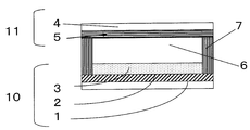
- FIG. 3 is a cross-sectional view showing an example of a dye-sensitized solar cell. Is the IR spectrum of the squarylium dye D-1 of the present invention.
- the squarylium compound of the present invention is represented by the above formula (1).
- This squarylium compound is used as a squarylium dye for photoelectric conversion represented by a photoelectric conversion element and a dye-sensitized solar cell.
- the squarylium compound represented by the formula (1) is also referred to as the squarylium dye of the present invention or the squarylium dye represented by the formula (1).
- the description of the photoelectric conversion element is represented by the dye-sensitized solar cell.
- R 1 is a C5-C20 alkyl group or a fluorine-substituted alkyl group represented by CF 3 (CF 2 ) m (CH 2 ) n.
- CF 3 CF 2
- m and n are Although it is an integer of 0 to 14 independently, the sum of m and n is 2 ⁇ m + n ⁇ 15.
- the effect of controlling the energy level of the dye by introducing the alkyl chain is small, and when the alkyl chain is too long, the N-alkyl nitrogen-containing heterocyclic ring that is the raw material
- the time required for synthesizing the salt becomes longer and the productivity is lowered.
- the solubility of the dye is lowered, making it difficult to adsorb the dye to the metal oxide.
- the alkyl chain includes a branched or straight chain alkyl group, preferably a straight chain alkyl group.
- R 1 is a fluorine-substituted alkyl group represented by CF 3 (CF 2 ) m (CH 2 ) n
- the orbital level of the dye can be controlled by the effect of the fluorine atom. It becomes easier and the electron transfer efficiency of the dye can be improved.
- m and n are independently integers of 0 to 14, and a range in which the sum of m and n is 2 to 14 is appropriate.
- a long fluorinated substituted alkyl group in which the total of m and n is 15 or more is not preferable because solubility in an organic solvent is reduced and dye adsorption becomes difficult.
- M and n are preferably an integer of 0 to 5, more preferably an integer of 1 to 3, and n is an integer of 0 to 9, more preferably an integer of 1 to 7.
- a preferable sum of m and n is an integer of 3 to 10.
- R 2 is a C1-C15 alkyl group or a phenyl group. More preferably, it is a C1 to C15 alkyl group.
- the alkyl group is too long, it is difficult to adsorb the dye to the semiconductor electrode due to a decrease in solubility. From this viewpoint, the number of carbon atoms of the alkyl group represented by R 2 is preferably in the range of 1-15.
- X represents C (CH 3 ) 2 , S, Se or NR 3 .
- R 3 is hydrogen or a C1-C15 alkyl group, preferably hydrogen or a C1-C6 alkyl group. Moreover, the alkyl group may have a substituent.
- X is preferably C (CH 3 ) 2 .
- Z and Y represent an atomic group that forms a ring structure containing a 5- or 6-membered ring together with a carbon atom.
- the ring structure containing these 5- or 6-membered rings may be further condensed with one or more aromatic rings, heterocyclic rings or aliphatic rings.
- Examples of ring structures containing 5- or 6-membered rings formed from Z include pyrrole, indolenine, benzoindolenine, naphthoindolenine, pyrimidine, pyrazole, imidazole, pyran, pyrazine or pyridazine ring structures, As the number of rings increases, the number of stages of synthesis increases and productivity decreases. Particularly preferred are pyrrole, indolenine, benzoindolenine, and naphthoindolenine ring structures.
- Examples of the ring structure containing a 5- or 6-membered ring formed from Y include benzene, naphthalene, anthracene, phenanthrene, tetracene, chrysene, triphenylene, tetraphen, pyrene, pentacene, picene, or perylene, As the number of rings increases, the number of stages of synthesis increases and productivity decreases. Particularly preferred are benzene, naphthalene, anthracene, and phenanthrene ring structures. More preferred are benzene, naphthalene and anthracene.
- R 1 when R 1 is an alkyl group, if the number of rings forming Z and Y increases, the energy level control of the dye becomes insufficient, and the electron transfer ability of the dye cannot be optimized. Is not enough. Therefore, as a ring structure forming Z and Y, Z is particularly preferably indolenine, and Y is particularly preferably benzene or naphthalene.
- Z is particularly preferably indolenine
- Y is particularly preferably benzene or naphthalene.
- R 1 when R 1 is a fluorine-substituted alkyl group represented by CF 3 (CF 2 ) m (CH 2 ) n, the effect of controlling the energy level of the dye is achieved by the effect of the fluorine atom.
- the number of rings forming Z and Y may be larger than when R 1 is an alkyl group.
- Z is particularly preferably indolenine, benzoindolenine or naphthoindolenine, and more preferably indolenine or benzoindolenine.
- Y is particularly preferably benzene, naphthalene or anthracene.
- a 1 and A 2 represent hydrogen or a carboxyl group, and at least one of A 1 and A 2 is a carboxyl group.
- a 1 and A 2 can be bonded to any ring when the ring structure is a condensed ring.
- a preferred squarylium compound is a squarylium compound represented by the formula (2) or the formula (3).
- R 1 is a C5-C20 alkyl group
- R 2 has the same meaning as in Formula (1).
- R 1 is a C5-C20 alkyl group
- preferred alkyl groups are the same as those in formula (1).
- squarylium compound represented by the formula (1) there is a squarylium compound represented by the formula (4) as a preferable squarylium compound.
- Z 1 represents an atomic group that forms a ring structure of indolenine, benzoindolenine, or naphthoindolenine with an adjacent nitrogen-containing ring. More preferred are indolenine and benzoindolenine.
- Y 1 represents an atomic group that forms a ring structure of benzene, naphthalene or anthracene together with a carbon atom.
- R 1 is a fluorine-substituted alkyl group represented by CF 3 (CF 2 ) m (CH 2 ) n, and m and n have the same meaning as in formula (1).
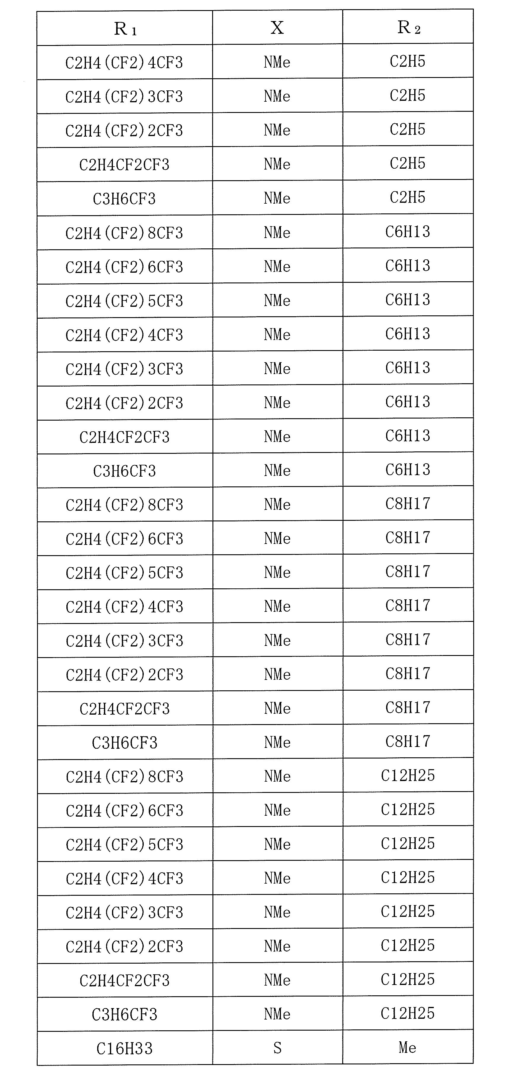
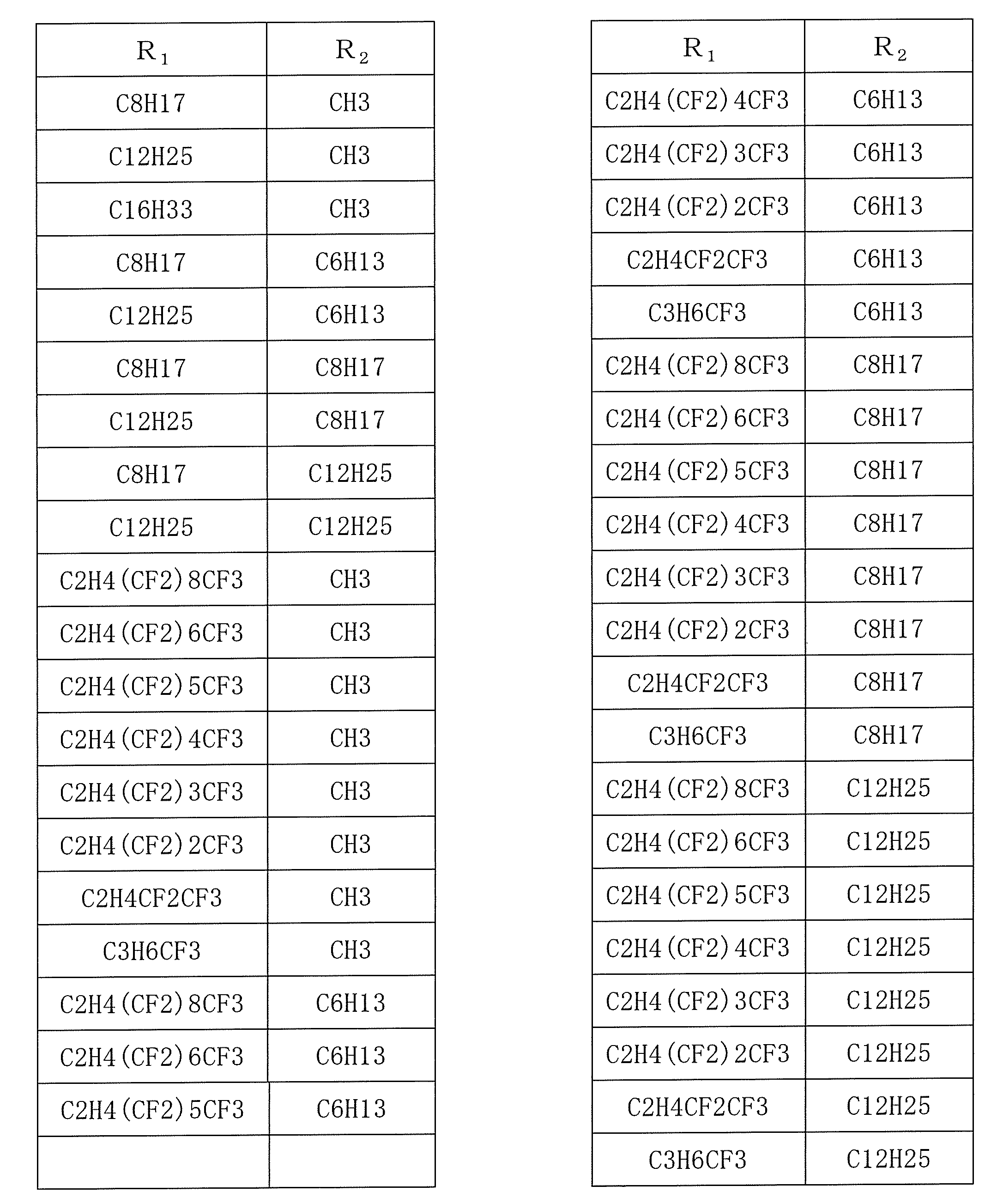
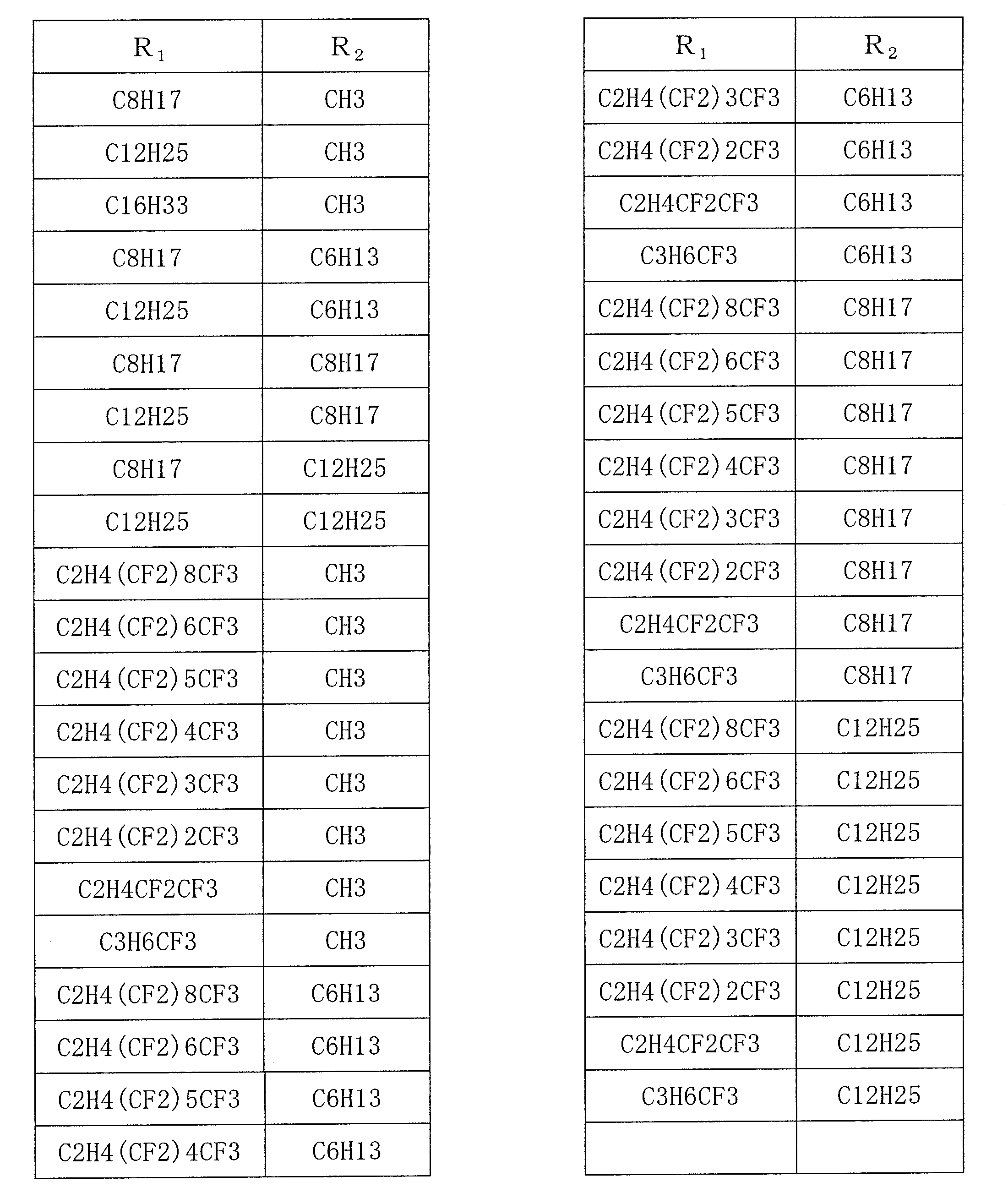
- R 1 , X and R 2 are specifically as shown in Tables 1 to 5. Specific compounds are specified by determining R 1 , X, and R 2 in formulas (2) to (3) and formulas (11) to (18). Therefore, by determining a set of R 1 , X, and R 2 , a total of 10 compounds of the formulas (2) to (3) and the formulas (11) to (18) are specified.
- Me is a methyl group.
- the squarylium dye represented by the formula (1) is preferably synthesized as follows.
- a nitrogen-containing heterocyclic compound (1a) having a carboxy group or an ester group is synthesized from a hydrazino-substituted aromatic carboxylic acid as a raw material, and then this nitrogen-containing heterocyclic compound (1a) is reacted with an alkyl halide to produce a carboxy group.
- an N-alkyl nitrogen-containing heterocyclic salt (1b) having an ester group is synthesized.
- this N-alkyl nitrogen-containing heterocyclic salt (1b) can be synthesized with an aryl-substituted squaric acid (1c).
- the nitrogen-containing heterocyclic compound (1a) having a carboxy group or an ester group can be synthesized with reference to Bioconjugate Chem., 2003, Vol. 14, 1048-1051. (R 4 represents hydrogen or a C1-C6 alkyl group.)
- N-alkyl nitrogen-containing heterocyclic salt (1b) having a carboxy group or an ester group can be synthesized with reference to Dyes and Pigments, 11, 1989, p21-35.
- N-alkyl nitrogen-containing heterocyclic salts (1b) having different carbon numbers and fluorine numbers can be synthesized by using halogenated alkyls (RI) in which the carbon number and fluorine number of the fluorine-substituted alkyl group are changed. .
- R of RI is an alkyl group and gives R 1 .
- R 4 represents hydrogen or a C1-C6 alkyl group.
- aryl-substituted squaric acid (1c) that is an intermediate of the squarylium dye represented by the formula (1)
- J. Am. Chem. Soc. 2004, 126, 21, p6590-6598 using squaric acid.
- aniline, aminonaphthalene, aminoanthracene, aminophenanthrene or the like in which the substituent on nitrogen is changed various aryl-substituted squaric acids can be synthesized.
- R ′ is an alkyl group or a phenyl group and gives R 2 .
- the squarylium dye represented by the formula (1) uses an N-alkyl nitrogen-containing heterocyclic salt (1b) having a carboxy group or an ester group and an aryl-substituted squaric acid (1c), and uses Dyes And Pigments, 11, 1989, p21- It can be synthesized with reference to 35.
- R 4 is a C1-C6 alkyl group
- the squarylium represented by the formula (1) is further converted by converting the ester group into a carboxy group by an alkali hydrolysis reaction using an alkali such as sodium hydroxide.
- a dye can be synthesized.
- R 4 represents hydrogen or a C1-C6 alkyl group.
- the squarylium dye represented by the formula (1) has a characteristic of having an absorption region on a relatively long wavelength side. Therefore, by using another dye having an absorption region on the shorter wavelength side together with the squarylium dye represented by the formula (1), light can be absorbed in a wide range of wavelengths.
- the other dye may have a maximum absorption wavelength at 400 to 580 nm.
- a preferred use ratio is in the range of 0.3 to 10, more preferably 1 to 4 by weight ratio of the former / the latter.
- the short wavelength side dye may be an organic dye or an inorganic dye.
- the absorption wavelength range of the sensitizing dye can be selected depending on the light source to be used. However, if necessary, the dye represented by the formula (1) or the formula (1) and the formula (25) is used. Still another dye can be selected to match the wavelength range of the target light source.
- dyes When two or more kinds of dyes are used, they are adsorbed on the dye-adsorbing metal oxide layer in a mixed state to be present, or the dyes are formed in different layers in the thickness direction of the dye-adsorbing metal oxide layer. It is preferable that it be adsorbed.
- the dye Since the dye is present adsorbed on the dye-adsorbing metal oxide layer, the dye preferably has an appropriate interlocking group that binds to the surface of the semiconductor fine particles made of the metal oxide.
- Preferred functional groups include —COOH group, —SO 3 H group, cyano group, —P (O) (OH) 2 group, —OP (O) (OH) 2 group, —OH group or oxime, dioxime, hydroxy
- Examples include chelating groups having ⁇ conductivity such as quinoline, salicylate and ⁇ -ketoenolate. Among these, a —COOH group is preferable, and the dye represented by the above formula (1) is also preferable in that it has a —COOH group.
- FIG. 1 is a cross-sectional view showing an example of a photoelectric conversion element.
- a counter electrode 11 provided with a conductive film 5 on a substrate 4, and an electrolyte layer 6 is disposed between both electrodes.
- the layer composed of the substrate 1 and the transparent conductive film 2 is a conductive support
- the semiconductor layer on which the sensitizing dye is adsorbed is the dye adsorbing metal oxide layer 3.
- the soot-dye-adsorbing metal oxide layer 3 is also called a semiconductor electrode because it constitutes a part of the electrode.
- the dye-adsorbing metal oxide layer 3 is a layer formed by coating and sintering as a single layer using titania or other metal oxide fine particles, or a layer formed by applying and sintering a plurality of times.
- the adsorbed semiconductor layer is composed of metal oxide particles such as titanium oxide particles and a sensitizing dye present so as to cover the surface of the particles. Light enters from the surface electrode 10 side.
- the dye-sensitized solar cell of the present invention has the same basic configuration as described above, but is made to work in an external circuit. And the method of using a photoelectric conversion element as a dye-sensitized solar cell may be a known method.
- the substrate 1 is not particularly limited as long as it is a transparent insulating material, and examples thereof include a normal glass plate and a plastic plate, and further, a flexible one may be used, for example, a PET resin. However, it is preferably a heat-resistant material that can withstand the step of baking titanium oxide with an upper limit of about 500 ° C., and a transparent glass plate can be mentioned.
- a transparent conductive film 2 is provided on the surface of the substrate 1 so as not to impair the transparency of the base material.
- ITO, FTO, ATO known as so-called transparent electrodes, or a combination thereof are combined. It may be a metal layer having a thickness that does not impair transparency.
- the method of providing these conductive films is not particularly limited, and includes spin coating, bar coating, screen printing using sputtering, vapor deposition (including CVD and PVD), spraying, laser ablation, or pasted materials. Known techniques can be used. Among them, a spray method or a sputtering or vapor deposition method performed in a gas phase is suitable.
- a sensitizing dye is adsorbed thereto.
- a metal oxide what is known as a photoelectric conversion material can be used, and titanium oxide, zinc oxide, tungsten oxide, and the like can be used. Of these, titanium oxide is preferable. Titanium oxide may be titanium hydroxide such as anatase type, rutile type, brookite type, titanium hydroxide or hydrous titanium oxide. Further, at least one of each element of Nb, V, or Ta may be doped so as to have a weight concentration (as a metal element) of 30 ppm to 5% with respect to titanium oxide. Such a metal oxide can be used in the present invention, but fine particles having an average particle diameter of 5 to 500 nm, preferably 10 to 200 nm are preferable.
- a metal oxide layer is formed on the transparent conductive film 2, but the method is not particularly limited.For example, each method such as spin coating, printing, spray coating, or the like is applied to a paste of metal oxide. It may be used. It is also possible to sinter for the purpose of sintering a metal oxide such as titanium oxide after film formation. Next, a dye for sensitization is adsorbed on the metal oxide to form a dye adsorbing metal oxide layer 3 as a dye adsorbing metal oxide.
- the present invention is characterized by a sensitizing dye, and other layers or materials may have a known structure or material, and are not limited to those having the structure shown in FIG.
- the materials constituting the soot-dye-adsorbing metal oxide layer 3 are a metal oxide and a dye that become a semiconductor. Since the metal oxide is preferably titanium oxide, the metal oxide may be represented by titanium oxide. Moreover, as a dye for dye sensitization, the squarylium dye represented by the above formula (1) may be used alone or in combination with other dyes.
- the soot pigment is dissolved in a solvent that dissolves it and adsorbed on a metal oxide layer such as a titania semiconductor layer.
- the adsorption solvent can be used as long as it can dissolve the dye.
- aliphatic alcohols such as methanol, ethanol, propanol and normal butanol
- nitrile solvents such as acetonitrile and propionitrile
- ketones such as acetone and methyl ethyl ketone
- carbonates such as dimethyl carbonate and diethyl carbonate
- lactones Caprolactams can be used.
- Methanol, ethanol or acetonitrile is preferred.
- a method for adsorbing the soot pigment a method of adsorbing the pigment by immersing the metal oxide layer in a pigment solution heated at room temperature or under reflux is common.
- a dye solution in which a coadsorbent such as deoxycholic acid or chenodeoxycholic acid (DCA) is dissolved in the dye solution may be used for adsorption.
- a supercritical fluid or a pressurized fluid may be used as a solvent, and the dye may be dissolved and adsorbed therein. Specifically, it is preferably adsorbed with a solution in which a dye is dissolved in a solvent obtained by adding an entrainer to supercritical carbon dioxide, pressurized carbon dioxide, or carbon dioxide.
- the method of dissolving multiple dyes in a solvent and adsorbing them as a single solution to the metal oxide layer is to obtain a dye-adsorbed metal oxide layer adsorbed in a state where the dyes are mixed. Suitable for.
- a method in which a plurality of dyes are dissolved in different solvents to form a plurality of solutions, and the solutions are sequentially used to adsorb to the metal oxide layer is a dye adsorption in which the dyes are adsorbed in layers in the thickness direction. Suitable for obtaining a metal oxide layer.
- the dye when a metal oxide layer is immersed in a first dye solution, the dye is adsorbed on the surface-side metal oxide layer and then the second dye is adsorbed.
- the dye is adsorbed on the metal oxide layer on the inner layer side of the layer on which the first dye is adsorbed. If necessary, this operation is repeated or a third dye solution is used to obtain a metal oxide layer in which the dye is adsorbed in multiple layers. Since the dye is sequentially adsorbed from the surface side of the metal oxide layer, when obtaining the dye-adsorbed metal oxide layer in which the organic dye is adsorbed in layers by the above method, the contact time and concentration with the dye solution are controlled. The thickness of each adsorption layer is adjusted. This method is also suitable when the solvent is a supercritical carbon dioxide gas or pressurized carbon dioxide fluid, or when the solvent is a supercritical carbon dioxide gas or pressurized carbon dioxide gas plus an entrainer.
- the metal oxide adsorbed with the dye may be further adsorbed with carboxylic acid in a CO 2 supercritical fluid.
- carboxylic acid in a CO 2 supercritical fluid.
- the effect of adsorbing carboxylic acids is known from the literature J. Photochem. And Photobio. A, Chem., 164 (2004) 117.
- CO formed with a dye-adsorbed metal oxide (which may be a substrate having a dye-adsorbed metal oxide layer) and carboxylic acid in a pressure range of 5 to 30 MPa and a temperature range of 40 to 60 ° C.
- carboxylic acid by placing the supercritical fluid or in the pressure CO 2, it can effectively adsorb the carboxylic acid.
- Preferred examples of the carboxylic acid include benzoic acid, acetic acid, anisic acid, and nicotinic acid. These carboxylic acids are preferably used in a state dissolved in an alcohol containing at least one of methanol, ethanol, propanol and butanol, and the carboxylic acid concentration is in the range of 0.01 to 10 mol / L. It is preferable.
- the surface electrode 10 composed of the substrate 1, the transparent conductive film 2, and the dye-adsorbing metal oxide layer 3 functions as a negative electrode.
- the other electrode (counter electrode) 11 acting as the positive electrode is disposed to face the surface electrode 10 as shown in FIG.
- the electrode serving as the positive electrode may be a conductive metal or the like, or may be a substrate 4 such as a normal glass plate or plastic plate provided with a conductive film 5 such as a metal film or a carbon film.
- An electrolyte layer 6 is provided between the surface electrode 10 serving as the negative electrode and the counter electrode 11 serving as the positive electrode.
- the type of the electrolyte is not particularly limited as long as it contains a redox species for reducing the dye after photoexcitation and electron injection into the semiconductor, and may be a liquid electrolyte, which is known in the art. It may be a gelled electrolyte obtained by adding a gelling agent (polymer or low molecular weight gelling agent) or a quasi-solid obtained by kneading an ionic liquid and a metal oxide.
- examples of the electrolyte used in the solution electrolyte iodine and iodide (LiI, NaI, KI, CsI, metal iodide such as CaI 2, tetraalkylammonium iodide, pyridinium iodide, such as imidazolium iodide 4 the combination of the combination of grade ammonium compound iodine salt, etc.), bromine and a bromide (LiBr, NaBr, KBr, CsBr , CaBr 2 , etc.
- metal bromides such as tetraalkylammonium bromide, quaternary ammonium compounds bromine salts such as pyridinium bromide, etc.
- poly Examples thereof include sulfur compounds such as sodium sulfide, alkyl thiol, and alkyl disulfide, viologen dyes, hydroquinone, and quinone.
- the electrolyte may be used as a mixture.
- a molten salt electrolyte having a high boiling point is preferable.
- the molten salt electrolyte composition includes a molten salt.
- the molten salt electrolyte composition is preferably liquid at room temperature.
- the molten salt as the main component is an electrolyte that is liquid at room temperature or has a low melting point, and a general example thereof is “Electrochemistry”, 1997, Vol. 65, No. 11, p. Pyridinium salts, imidazolium salts, and triazolium salts described in No. 923.
- the molten salt may be used alone or in combination of two or more.
- Alkali metal salts such as LiI, NaI, KI, LiBF 4 , CF 3 COOLi, CF 3 COONa, LiSCN, and NaSCN can also be used in combination.
- the molten salt electrolyte composition contains iodine.
- the molten salt electrolyte composition preferably has low volatility and preferably does not contain a solvent.
- the molten salt electrolyte composition may be used after gelation.
- the compound has a low viscosity and high ion mobility and can exhibit excellent ionic conductivity.
- solvents include carbonate compounds such as ethylene carbonate and propylene carbonate, heterocyclic compounds such as 3-methyl-2-oxazolidinone, ether compounds such as dioxane and diethyl ether, ethylene glycol dialkyl ether, propylene glycol dialkyl ether , Chain ethers such as polyethylene glycol dialkyl ether and polypropylene glycol dialkyl ether, alcohols such as methanol, ethanol, ethylene glycol monoalkyl ether, propylene glycol monoalkyl ether, polyethylene glycol monoalkyl ether and polypropylene glycol monoalkyl ether, ethylene Glycol, propylene glycol, polyethylene glycol, polypropylene glycol Lumpur, polyhydric alcohols such as glycerin, acetonitrile,
- the method of providing the electrolyte layer 6 is not particularly limited.
- a film-like spacer 7 may be disposed between both electrodes to form a gap, and an electrolyte may be injected into the gap.
- a method may be employed in which the positive electrode is loaded at an appropriate interval after the electrolyte is applied to the electrode. It is desirable to seal both electrodes and their surroundings so that the electrolyte does not flow out, but the sealing method and the material of the sealing material are not particularly limited.
- the solid content is added to 70 g of methanol, heated to 30 ° C., dispersed and dissolved, and the insoluble content is filtered.
- the filtrate is crystallized by adding 160 g of water and filtered.
- 3-Trimethyl-5-carboxy-indole was obtained.
- Nn-alkylcarboxyindolenine salt nitrogen-containing heterocyclic salt having carboxy group
- Nn-alkylcarboxyindolenine salt nitrogen-containing heterocyclic salt having carboxy group
- Synthesis of dimethylaniline substituted squaric acid is carried out as follows. 90 mmol of 3,4-dihydroxy-3-cyclobutene-1,2-dione is added to 100 ml of dichloromethane, and 180 mmol of oxalyl dichloride is added using a dropping funnel over 10 minutes while cooling the reaction vessel with ice. After completion of the dropwise addition, the mixture is reacted by stirring for 4 hours while refluxing. After completion of the reaction, dichloromethane was distilled off and vacuum-dried to obtain 90 mmol of white crystals.
- Example 2 When synthesizing the indolenine salt, squarylium dye D-2 was obtained in the same manner as in Example 1 except that 1-iodohexane was used instead of 1-iodododecane.
- Example 3 When synthesizing the indolenine salt, squarylium dye D-3 was obtained in the same manner as in Example 1 except that 1-iodoeicosane was used instead of 1-iodododecane.
- Example 4 When synthesizing indolenine, 4-hydrazino-1-carboxynaphthalene is used instead of 4-hydrazinobenzoic acid, and when synthesizing N-alkylcarboxyindolenine salts, instead of 1-iodododecane, When synthesizing an aryl-substituted squaric acid using 1-iodohexane, squarylium was used in the same manner as in Example 1 except that N, N-dioctyl-1-aminoanthracene was used instead of N, N-dimethylaniline. Dye D-12 was obtained.
- Example 5 A squarylium dye D-5 was obtained in the same manner as in Example 1 except that N, N-didodecylaniline was used instead of N, N-dimethylaniline when synthesizing the aryl-substituted squaric acid.
- Example 6 A squarylium dye D-10 was obtained in the same manner as in Example 1 except that N, N-dimethylnaphthalene was used instead of N, N-dimethylaniline when synthesizing the aryl-substituted squaric acid.
- Example 7 When synthesizing indolenine, 4-hydrazino-1-carboxynaphthalene is used instead of 4-hydrazinobenzoic acid, and when synthesizing an N-alkylcarboxyindolenine salt, instead of 1-iodododecane, Synthesis of aryl-substituted squaric acid using 1,1,1,2,2,3,3,4,4-nonafluoro-6-iodohexane and 3-methoxypropionitrile instead of acetonitrile as solvent In this case, squarylium dye D-11 was obtained in the same manner as in Example 1 except that N, N-dioctyl-1-aminoanthracene was used instead of N, N-dimethylaniline.
- Example 8 When synthesizing indolenine, 4-hydrazino-1-carboxynaphthalene is used instead of 4-hydrazinobenzoic acid, and when synthesizing N-alkylcarboxyindolenine salts, instead of 1-iodododecane, Except for using N, N-dioctyl-1-aminoanthracene instead of N, N-dimethylaniline when synthesizing aryl-substituted squaric acid using 1,1,1-trifluoro-4-iodobutane In the same manner as in Example 1, squarylium dye D-13 was obtained.
- Comparative Example 2 A squarylium dye D-6 was obtained in the same manner as in Example 1 except that 1-iodoethane was used in place of 1-iodododecane when the N-alkylcarboxyindolenine salt was synthesized.
- Comparative Example 3 A squarylium dye D-7 was obtained in the same manner as in Example 1 except that 1-iodotetracosane was used instead of 1-iodododecane in the synthesis of the N-alkylcarboxyindolenine salt.
- Comparative Example 5 A squarylium dye D-9 was obtained in the same manner as in Example 1 except that N, N-dihexadecanylaniline was used instead of N, N-dimethylaniline when synthesizing the aryl-substituted squaric acid.
- the chemical formula of squarylium dye D-10 is represented by the general formula (27), the chemical formulas of D-11 to 13 are represented by the general formula (28), and X, R 1 and R 2 are specified in Table 13 to be specified.
- Table 12 shows the maximum absorption wavelength and absorption edge.
- Example 9 As a glass substrate with a transparent conductive film of 30 mm ⁇ 25 mm ⁇ 3 mm, a glass substrate with FTO (fluorine-doped tin oxide) film (trade name: Low-E glass) made of Japanese plate glass was used. Next, a titanium oxide film was formed on the conductive film of the substrate with the conductive film. As titanium oxide, a commercially available titanium oxide paste (D paste made by Solaronics) was used. A laminated board in which a titanium oxide layer having a thickness of 15 ⁇ m was formed by coating this onto a conductive film of a substrate with a conductive film by a squeegee printing method in a range of 5 mm ⁇ 5 mm, drying and baking at 450 ° C. Obtained.
- FTO fluorine-doped tin oxide
- D-1 was used as the dye. This was dissolved in ethanol so that 2.5 ⁇ 10 ⁇ 4 mol / L and DCA were 2.5 ⁇ 10 ⁇ 2 mol / L.
- the dye was adsorbed by an immersion method. Specifically, a solution is prepared by dissolving in a solvent, a dye solution is put in a container, and a laminated board on which the titanium oxide layer is formed is placed, immersed, adsorbed, and then the laminated board on which the dye is adsorbed from the container. I took it out.
- thermoplastic adhesive (trade name of Mitsui DuPont Polychemical Co., Ltd .; High Milan Sheet) made of ionomer resin with a thickness of 50 ⁇ m is formed on four sides of the outer periphery of 5 mm ⁇ 5 mm on which the titanium oxide film of this laminate is formed. In order to be able to inject, it was pasted so as to provide a gap of about 1 mm at two locations on the outer periphery.
- This thermoplastic adhesive is not only a sealing material but also serves as a spacer between the two electrodes.
- thermoplastic adhesive film On which a platinum film having a thickness of 10 nm serving as a positive electrode was formed by a sputtering method was bonded through the thermoplastic adhesive film so that the platinum side was opposed to the titanium oxide side.
- an acetonitrile solution containing 0.5M LiI, 0.5M t-butylpyridine, and 0.05M iodine as the main component is filled between the substrate and the positive electrode using capillary action. It was.
- the gap was sealed with an epoxy resin adhesive to obtain a photoelectric conversion element.
- Example 10 A photoelectric conversion element was obtained in the same manner as in Example 9 except that the dye D-2 was used instead of the dye D-1.
- Example 11 Dye D-1 is dissolved in 2.5 x 10⁻⁴ mol / L, Dye-149 is dissolved in ethanol, 0.75 x 10⁻⁴ mol / L, and DCA is dissolved in 3.0 x 10⁻³ mol / L.
- a photoelectric conversion element was obtained in the same manner as in Example 9 except that the dye adsorption by the dye layered immersion method was performed.
- Example 12 A photoelectric conversion element was obtained in the same manner as Example 9 except that Dye D-3 was used instead of Dye D-1.
- Comparative Example 10 A photoelectric conversion element was obtained in the same manner as in Example 9 except that the dye D-4 was used instead of the dye D-1.
- Example 14 A photoelectric conversion device was obtained in the same manner as in Example 9 except that the dye D-5 was used instead of the dye D-1.
- Example 15 A photoelectric conversion element was obtained in the same manner as in Example 9 except that the dye D-10 was used instead of the dye D-1.
- Example 16 A photoelectric conversion element was obtained in the same manner as in Example 9 except that the dye D-11 was used instead of the dye D-1.
- Example 17 A photoelectric conversion element was obtained in the same manner as in Example 9 except that the dye D-13 was used instead of the dye D-1.
- Comparative Example 7 A photoelectric conversion element was obtained in the same manner as in Example 9 except that the dye D-6 was used instead of the dye D-1.
- Comparative Example 7 A photoelectric conversion element was obtained in the same manner as Example 9 except that Dye D-7 was used instead of Dye D-1.
- Comparative Example 8 A photoelectric conversion element was obtained in the same manner as Example 9 except that Dye D-8 was used instead of Dye D-1.
- Comparative Example 9 A photoelectric conversion element was obtained in the same manner as Example 9 except that Dye D-9 was used instead of Dye D-1.
- Example 13 A photoelectric conversion element was obtained in the same manner as in Example 9 except that the dye D-12 was used instead of the dye D-1.
- Comparative Example 11 A photoelectric conversion element was obtained in the same manner as in Example 9 except that the dye D-149 was used instead of the dye D-1.
- the photoelectric conversion elements prepared in Examples and Comparative Examples were used as dye-sensitized solar cells, and the battery characteristics were measured using a solar simulator. In the measurement, pseudo solar light with AM 1.5 and 100 mW / cm 2 was used, and the characteristics were evaluated using an IV curve tracer. The results of measuring the conversion efficiency (%) are shown in Table 13.
- the quantum yield for each wavelength was measured using an IPCE (Incident-Photon-to-Current Conversion Efficiency) and a spectral sensitivity measuring device.
- IPCE-1 is the short wavelength side dye maximum absorption wavelength (nm)
- IPCE-2 is the long wavelength side dye maximum absorption wavelength (nm)
- Dye 1 is a short wavelength side dye
- Dye 2 is a long wavelength side dye.
- D is an immersion method
- LD is a dye layered immersion method.
- the squarylium compound of the present invention is useful as a squarylium dye, which is a sensitizing dye used in a photoelectric conversion element or a dye-sensitized solar cell.
- the photoelectric conversion element or dye-sensitized solar cell using this squarylium dye has high photoelectric conversion efficiency in the near infrared light region. Further, by using a dye that absorbs light at a shorter wavelength side together with the squarylium compound represented by the formula (1), the photoelectric conversion efficiency is improved by the synergistic effect of the two dyes without using an expensive Ru dye. More improved.
- the squarylium dye of the present invention provides a photoelectric conversion element having a high photoelectric conversion efficiency or a dye-sensitized solar cell composed thereof.
Landscapes
- Chemical & Material Sciences (AREA)
- Organic Chemistry (AREA)
- Physics & Mathematics (AREA)
- Spectroscopy & Molecular Physics (AREA)
- Engineering & Computer Science (AREA)
- Materials Engineering (AREA)
- Chemical Kinetics & Catalysis (AREA)
- Electrochemistry (AREA)
- General Chemical & Material Sciences (AREA)
- Photovoltaic Devices (AREA)
- Hybrid Cells (AREA)
Abstract
近赤外領域における光電変換効率の向上可能な光電変換素子及び太陽電池用の色素を提供し、これを用いた光電変換素子及び色素増感太陽電池を提供する。 上記色素は、下記式(1)で表されるスクアリリウム化合物及びスクアリリウム色素である。 式(1)において、Y及びZは各々独立して、炭素原子とともに5又は6員環を含有する環構造を形成する原子団を表す。A1及びA2は各々独立して、水素又はカルボキシル基を表し、A1及びA2のうち少なくとも一つは5又は6員環に結合するカルボキシル基である。XはC(CH3)2、S、Se又はNR3を表し、R3は水素又はC1~C15のアルキル基を示す。R1はC5~C20のアルキル基又はCF3(CF2)m(CH2)nで表されるフッ素置換アルキル基であり、mとnは独立に0~14の整数を表すが、2≦m+n<15である。R2はC1~C15のアルキル基もしくはフェニル基を示す。
Description
本発明は、スクアリリウム色素、この色素を用いる光電変換素子、及び色素増感太陽電池に代表される光電変換電池に関する。
光電変換素子は、光センサー、太陽電池等の光発電装置に使用されている。色素によって増感された半導体微粒子を用いる光電変換素子が特許文献1等で知られている。
太陽電池としては、単結晶、多結晶あるいはアモルファスのシリコン半導体を用いた太陽電池が、電卓などの電気製品や住宅用などに広く用いられている。しかしながら、このようなシリコン半導体を用いた太陽電池の製造には、プラズマCVDや高温結晶成長プロセスなどの高精度プロセスが用いられるため、多大のエネルギーを必要とすると共に、真空を必要とする高価な装置が必要なために製造コストが高くなっている。
そこで、低コストで製造可能な太陽電池として、例えば、酸化チタンのような酸化物半導体にルテニウム金属錯体のような光増感色素を吸着させた材料を用いた色素増感太陽電池が提案されている。色素増感太陽電池は、少なくとも導電性支持体と色素によって増感された色素吸着金属酸化物層を有する。具体的には、導電性支持体は、例えばインジウム添加酸化スズのような透明導電層を設けた透明ガラス板あるいは透明樹脂板のような透明絶縁材料からなる。色素吸着金属酸化物層は、例えば色素を表面に吸着した酸化チタンのような半導体層からなる。
色素増感太陽電池は、導電性支持体の透明導電層側に、例えばルテニウム錯体からなる色素を表面に吸着した色素吸着金属酸化物層を半導体層として形成した負極と、正極となる白金などの金属層あるいは導電層を設けた透明ガラス板あるいは透明樹脂板のような透明絶縁材料との間に電解質の液を封入したものがある。色素増感太陽電池に光が照射されると、負極では光を吸収した色素の電子が励起し、励起した電子が半導体層に移動し、更に透明電極へと導かれ、正極では導電層からくる電子により電解質を還元する。還元された電解質は色素に電子を伝えることで酸化され、このサイクルで色素増感太陽電池が発電すると考えられている。
現在、色素増感太陽電池はシリコン太陽電池に比して照射光エネルギーに対する発電エネルギー効率が低く、その効率を上げることが実効的な色素増感太陽電池を製造する上での重要な課題となっている。色素増感太陽電池の効率は、それを構成する各要素の特性や、更にそれら要素の組み合わせによっても影響を受けると考えられており、さまざまな試みがなされている。中でも、光増感作用を持つ色素について、より高効率な増感色素の開発に注力されている。現在知られている高効率色素としてRu色素があるが、遷移金属であるRuは高価なため、安価で高効率の色素の開発に注力されている。また、これらの色素は可視光領域の光電変換効率は高いが、近赤外領域の光電変換効率が低く、近赤外領域近傍に吸収帯を有する色素の開発が望まれている。
この近赤外領域近傍に吸収帯を有する有機色素については、特許文献1、非特許文献1、非特許文献2等でいくつかの化合物が知られている。また、近赤外領域近傍に吸収帯を有する有機色素と他の領域に吸収帯を有する有機色素を混合する色素増感太陽電池については、特許文献2、非特許文献3、非特許文献4等に開示されている。また、スクアリリウム色素についても、これらの文献で知られている。
Chem Lett, 2006, 35, 6, p666-667
Chemical Communication, 2007, p4690-4682
J. Am. Chem. Soc., 2007, 129, p10320-10321
Angew. Chem. Int. Ed., 2008, 120, p8383-8387
特許文献1は光電変換素子及び色素増感太陽電池を開示し、それに使用されるポリメチン色素を例示している。特許文献1において使用されるポリメチン色素は、一般式で表わされており、膨大な数の化合物が含まれるが、例示された化合物の中にカルボキシインドレニン構造とエチル基を有するスクアリリウム色素と、カルボキシエチル基を有するスクアリリウム色素がある。しかし、スクアリリウム骨格に結合する2つの芳香族原子団がともにメチン基を介して結合する対称型のスクアリリウム色素の開示に限定される。
特許文献2、非特許文献4には短波長領域色素領域と長波長領域色素を混合する色素増感太陽電池が例示されているが、スクアリリウム色素については特許文献1とほぼ同様な開示をするにとどまる。
特許文献3は、光電変換素子及び色素増感太陽電池を開示し、それに使用されるスクアリリウム色素およびクマリン色素を例示している。特許文献3において使用されるスクアリウム色素は、スクアリリウム環に環状構造が直結した一般式で表わされており、膨大な数の化合物が含まれるが、例示された化合物の中にスクアリリウム骨格に結合する2つの芳香族原子団のうち片方がメチン基を介して結合する非対称型スクアリリウム色素の開示はない。
非特許文献1には例示された化合物の中にカルボキシエチル基が窒素上に置換したインドレニン構造とアニリン構造を有する非対称型スクアリリウム色素がある。しかし、カルボキシル基が主鎖のパイ共役系にメチレン基を介して結合しており、色素から電極への電子の移動効率が落ちるため、発電効率が劣る。
非特許文献2及び非特許文献3には、スクアリリウム骨格に結合する2つの原子団のうち、一方がメチル基又はエチル基を有するインドレニン骨格であり、他方がC8アルキルを有するカルボキシインドレニン骨格であるスクアリリウム色素が例示されているが、変換効率が低い。
特許文献2、非特許文献4には短波長領域色素領域と長波長領域色素を混合する色素増感太陽電池が例示されているが、スクアリリウム色素については特許文献1とほぼ同様な開示をするにとどまる。
光電変換素子及び太陽電池用の色素において近赤外領域における吸収がありながら高い光電変換効率を有するものは知られておらず、広範囲な領域において光電変換効率の向上可能な色素増感太陽電池及び光電変換素子を提供することができていない。
本発明は、上記の課題に鑑みてなされたものであり、近赤外領域における光電変換効率の向上可能な新規な光電変換素子及び太陽電池用の色素を提供し、これを用いた光電変換素子及び色素増感太陽電池を提供することを目的とする。また、失活し難い近赤外領域に適したスクアリリウム色素を提供することを目的とする。更に、広範囲な領域において光電変換効率の向上可能な色素増感太陽電池及び光電変換素子を提供することを目的とする。
本発明は、下記式(1)で表わされるスクアリリウム化合物に関する。
 式(1)において、Y及びZは各々独立して、炭素原子とともに5又は6員環を含有する環構造を形成する原子団を表す。A1及びA2は各々独立して、水素又はカルボキシル基を表し、A1及びA2のうち少なくとも一つは5又は6員環に結合するカルボキシル基である。XはC(CH3)2、S、Se又はNR3を表し、R3は水素又はC1~C15のアルキル基を示す。R1はC5~C20のアルキル基又はCF3(CF2)m(CH2)nで表されるフッ素置換アルキル基であり、mとnは独立に0~14の整数を表すが、2≦m+n<15である。R2はC1~C15のアルキル基もしくはフェニル基を示す。
式(1)において、Zにより形成される環構造が、ピロール、インドレニン、ベンゾインドレニン、ナフトインドレニン、ピリミジン、ピラゾール、イミダゾール、ピラン、ピラジン又はピリダジンの環構造であることが好ましい。
式(1)において、Yにより形成される環構造が、ベンゼン、ナフタレン、アントラセン、フェナントレン、テトラセン、クリセン、トリフェニレン、テトラフェン、ピレン、ペンタセン、ピセン又はペリレンの環構造であることが好ましい。
好ましいスクアリリウム化合物としては、下記式(2)、式(3)及び式(4)で表されるスクアリリウム化合物がある。
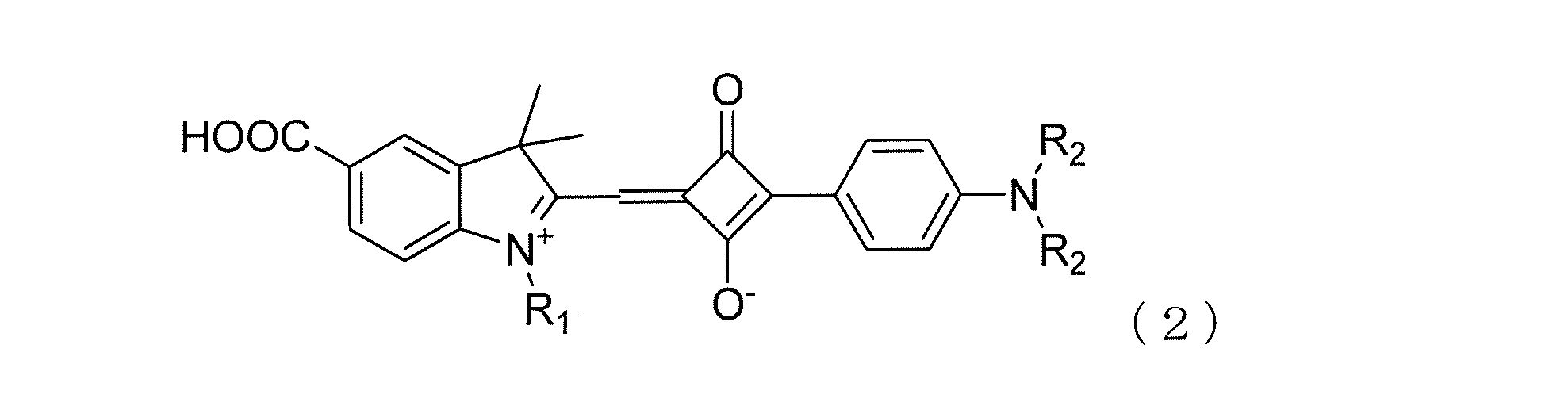

式(2)および式(3)において、R1はC5~C20のアルキル基である。R2はC1~C15のアルキル基もしくはフェニル基を示す。R1は好ましくはC8~C20、さらに好ましくはC13~C20のアルキル基である。
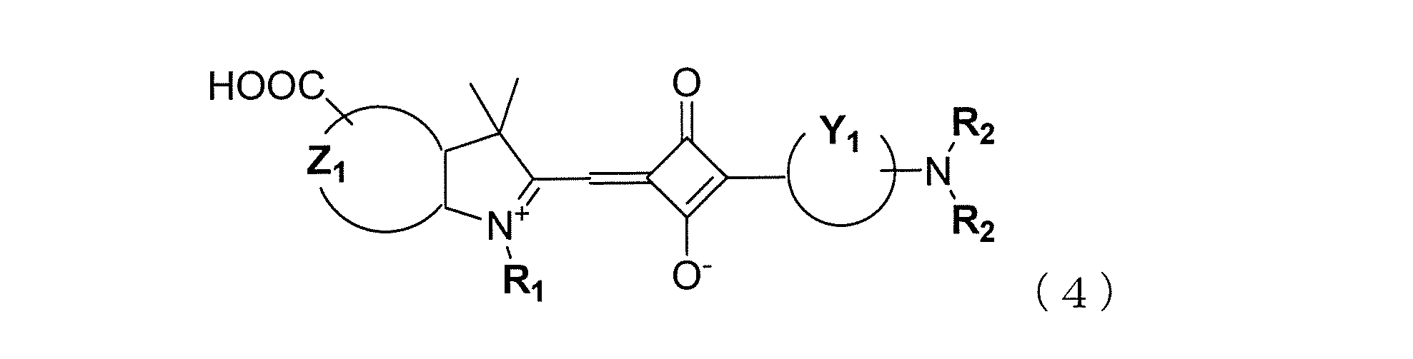
また、本発明は、少なくとも色素によって増感された色素吸着金属酸化物層を有する光電変換素子又は色素増感太陽電池用のスクアリリウム色素において、スクアリリウム色素が上記のスクアリリウム化合物からなることを特徴とするスクアリリウム色素に関する。上記スクアリリウム色素は、色素増感太陽電池用のスクアリリウム色素として優れる。
更に、本発明は、少なくとも色素によって増感された色素吸着金属酸化物層を有する光電変換素子又は色素増感光太陽電池において、該色素として上記のスクアリリウム色素を含むことを特徴とする光電変換素子又は色素増感光太陽電池に関する。
本発明のスクアリリウム化合物は上記式(1)で表される。このスクアリリウム化合物は、光電変換素子、色素増感太陽電池で代表される光電変換用のスクアリリウム色素として使用される。以下、式(1)で表されるスクアリリウム化合物を、本発明のスクアリリウム色素又は式(1)で表されるスクアリリウム色素ともいう。
ここで、色素増感太陽電池は光電変換素子の1種であるので、光電変換素子の説明を色素増感太陽電池で代表する。
式(1)において、R1はC5~C20のアルキル基、又はCF3(CF2)m(CH2)nで表されるフッ素置換アルキル基であり、フッ素置換アルキル基において、mとnは独立に0~14の整数であるが、mとnの合計が2≦m+n<15である。
上記アルキル基又はフッ素置換アルキル基のアルキル鎖が短すぎる場合は、アルキル鎖導入による色素のエネルギー準位制御の効果が小さく、アルキル鎖が長すぎる場合は、原料であるN-アルキル含窒素複素環塩を合成する際の所要時間が長くなり、生産性が低下する。また、色素の溶解性が低下して金属酸化物への色素吸着が困難になる。
また、式(1)において、R1のようなアルキル基の炭素数は多い程、色素同士の会合を阻害し、太陽電池の効率を向上させることができることは公知である。しかし、鋭意検討の結果、本発明における骨格において、R1の炭素数が大きすぎると太陽電池の効率が低下し、適度な範囲が存在することが分かった。これは、色素分子の軌道準位の観点から、色素の電子授受効率に影響を与えるためである。具体的には、アルキル基の場合はC5~C20が適度な範囲であるが、C8~C20が好ましく、C13~C20がさらに好ましい。
R1において、アルキル鎖としては、分岐又は直鎖のアルキル基があるが、好ましくは直鎖のアルキル基である。
R1において、アルキル鎖としては、分岐又は直鎖のアルキル基があるが、好ましくは直鎖のアルキル基である。
一方、式(1)において、R1がCF3(CF2)m(CH2)nで表されるフッ素置換アルキル基である場合、フッ素原子の効果により色素の軌道準位を制御することがより容易となり、色素の電子授受効率を向上することができる。具体的には、mとnは独立に0~14の整数であり、且つmとnの合計が2~14である範囲が適度である。mとnの合計が15以上のような長いフッ化置換アルキル基においては、有機溶媒への溶解性が低下し、色素吸着が困難となるために好ましくない。好ましいm及びnは、mは0~5の整数、より好ましくは1~3の整数であり、nは0~9の整数、より好ましくは1~7の整数である。好ましいmとnの合計は、3~10の整数である。
式(1)において、R2はC1~C15のアルキル基もしくはフェニル基である。より好ましくはC1~C15のアルキル基である。アルキル基が長すぎる場合は、溶解性の低下により半導体電極への色素吸着が困難になる。この観点からR2のアルキル基の炭素数は1~15の範囲が好ましい。
式(1)において、XはC(CH3)2、S、Se又はNR3を示す。R3は、水素又はC1~C15のアルキル基、好ましくは、水素又はC1~C6のアルキル基である。また、アルキル基は置換基を有してもよい。Xは、好ましくはC(CH3)2である。
式(1)において、Z及びYは炭素原子とともに5又は6員環を含有する環構造を形成する原子団を表す。これらの5又は6員環を含有する環構造は、更に1又は複数の芳香族環、複素環又は脂肪族環が縮合していても良い。
Zから形成される5又は6員環を含有する環構造としては、ピロール、インドレニン、ベンゾインドレニン、ナフトインドレニン、ピリミジン、ピラゾール、イミダゾール、ピラン、ピラジン又はピリダジンの環構造が挙げられるが、環の数が多くなると合成の段階が増えて生産性が低下する。特に好ましくはピロール、インドレニン、ベンゾインドレニン、ナフトインドレニンの環構造が挙げられる。
Yから形成される5又は6員環を含有する環構造としては、ベンゼン、ナフタレン、アントラセン、フェナントレン、テトラセン、クリセン、トリフェニレン、テトラフェン、ピレン、ペンタセン、ピセン又はペリレンの環構造が挙げられるが、環の数が多くなると合成の段階が増えて生産性が低下する。特に好ましくは、ベンゼン、ナフタレン、アントラセン、フェナントレンの環構造が挙げられる。更に好ましくは、ベンゼン、ナフタレン、アントラセンである。
式(1)において、R1がアルキル基の場合は、Z及びYを形成する環の数が多くなると、色素のエネルギー準位制御が不十分となり、色素の電子授受能力を最適化できないため効率が十分でなくなる。そのため、Z及びYを形成する環構造としては、Zはインドレニンが特に好ましく、Yはベンゼン又はナフタレンが特に好ましい。
一方で、式(1)において、R1がCF3(CF2)m(CH2)nで表されるフッ素置換アルキル基である場合、フッ素原子の効果により色素のエネルギー準位制御の効果が高く、R1がアルキル基の場合と比較して、Z及びYを形成する環の数が多くても良い。具体的には、Z及びYを形成する環構造としては、Zはインドレニン、ベンゾインドレニン又はナフトインドレニンが特に好ましく、更に好ましくはインドレニン、ベンゾインドレニンである。Yはベンゼン、ナフタレン又はアントラセンが特に好ましい。
一方で、式(1)において、R1がCF3(CF2)m(CH2)nで表されるフッ素置換アルキル基である場合、フッ素原子の効果により色素のエネルギー準位制御の効果が高く、R1がアルキル基の場合と比較して、Z及びYを形成する環の数が多くても良い。具体的には、Z及びYを形成する環構造としては、Zはインドレニン、ベンゾインドレニン又はナフトインドレニンが特に好ましく、更に好ましくはインドレニン、ベンゾインドレニンである。Yはベンゼン、ナフタレン又はアントラセンが特に好ましい。
式(1)において、A1及びA2は水素又はカルボキシル基を表し、A1及びA2の少なくとも一つはカルボキシル基である。このA1及びA2は、上記環構造が縮合環である場合は、任意の環に結合することができる。
式(1)で表されるスクアリリウム化合物において、好ましいスクアリリウム化合物として上記式(2)又は式(3)で表されるスクアリリウム化合物がある。
式(2)及び式(3)において、R1はC5~C20のアルキル基であり、R2は、式(1)と同じ意味を有する。R1がC5~C20のアルキル基である場合、好ましいアルキル基は式(1)と同じである。
式(2)及び式(3)において、R1はC5~C20のアルキル基であり、R2は、式(1)と同じ意味を有する。R1がC5~C20のアルキル基である場合、好ましいアルキル基は式(1)と同じである。
また、式(1)で表されるスクアリリウム化合物において、好ましいスクアリリウム化合物として上記式(4)で表されるスクアリリウム化合物がある。
式(4)において、Z1は、隣接する含窒素環とともにインドレニン、ベンゾインドレニン又はナフトインドレニンの環構造を形成する原子団を表す。より好ましくはインドレニン、ベンゾインドレニンである。Y1は、炭素原子とともにベンゼン、ナフタレン又はアントラセンの環構造を形成する原子団を表す。R1はCF3(CF2)m(CH2)nで表されるフッ素置換アルキル基であり、mとnは式(1)と同じ意味を有する。
式(4)において、Z1は、隣接する含窒素環とともにインドレニン、ベンゾインドレニン又はナフトインドレニンの環構造を形成する原子団を表す。より好ましくはインドレニン、ベンゾインドレニンである。Y1は、炭素原子とともにベンゼン、ナフタレン又はアントラセンの環構造を形成する原子団を表す。R1はCF3(CF2)m(CH2)nで表されるフッ素置換アルキル基であり、mとnは式(1)と同じ意味を有する。
以下に式(1)で表されるスクアリリウム化合物の好ましい具体例を示す。


式(2)~(3)、及び式(11)~(18)において、R1、X、R2の好ましい例は具体的には表1~5の通りである。式(2)~(3)、及び式(11)~(18)のR1、X、R2が定まることにより具体的な化合物が特定される。したがって、一組のR1、X、R2が定まることにより、式(2)~(3)、及び式(11)~(18)の合計10個の化合物が特定される。表中、Meはメチル基である。




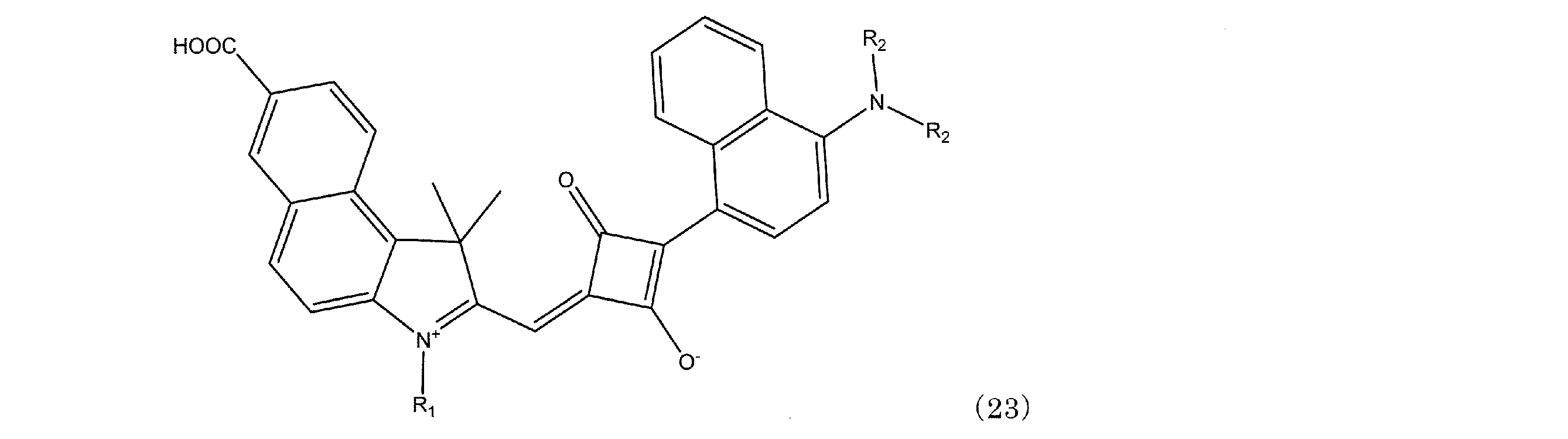
本発明のスクアリウム化合物の他の好ましい具体例を、化学式とそれに含まれるR1、R2を示すことにより例示する。化学式(19)~(24)に含まれるR1、R2を、それぞれ表6~11に示す。







式(1)で表わされるスクアリリウム色素は、次のようにして合成することが好ましい。ヒドラジノ置換芳香族カルボン酸を原料にカルボキシ基又はエステル基を有する含窒素複素環化合物(1a)を合成し、次にこの含窒素複素環化合物(1a)とハロゲン化アルキルとを反応させ、カルボキシ基又はエステル基を有するN-アルキル含窒素複素環塩(1b)を合成する。次に、このN-アルキル含窒素複素環塩(1b)とアリール置換スクアリン酸(1c)とを反応させて合成することができる。
カルボキシ基又はエステル基を有する含窒素複素環化合物(1a)は、Bioconjugate Chem.,2003,Vol.14,1048-1051を参考に合成することができる。
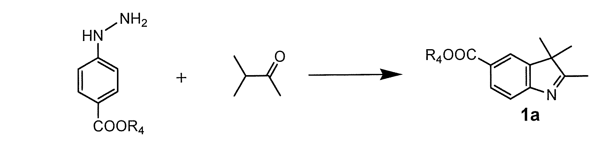
(R4は水素又はC1~C6のアルキル基を示す。)
(R4は水素又はC1~C6のアルキル基を示す。)
カルボキシ基又はエステル基を有するN-アルキル含窒素複素環塩(1b)はDyes and Pigments, 11, 1989, p21-35を参考に合成することができる。フッ素置換アルキル基の炭素数及びフッ素数を変化させたハロゲン化アルキル(R-I)を使用することにより、炭素数及びフッ素数の異なるN-アルキル含窒素複素環塩(1b)を合成することができる。R-IのRはアルキル基であり、R1を与える。

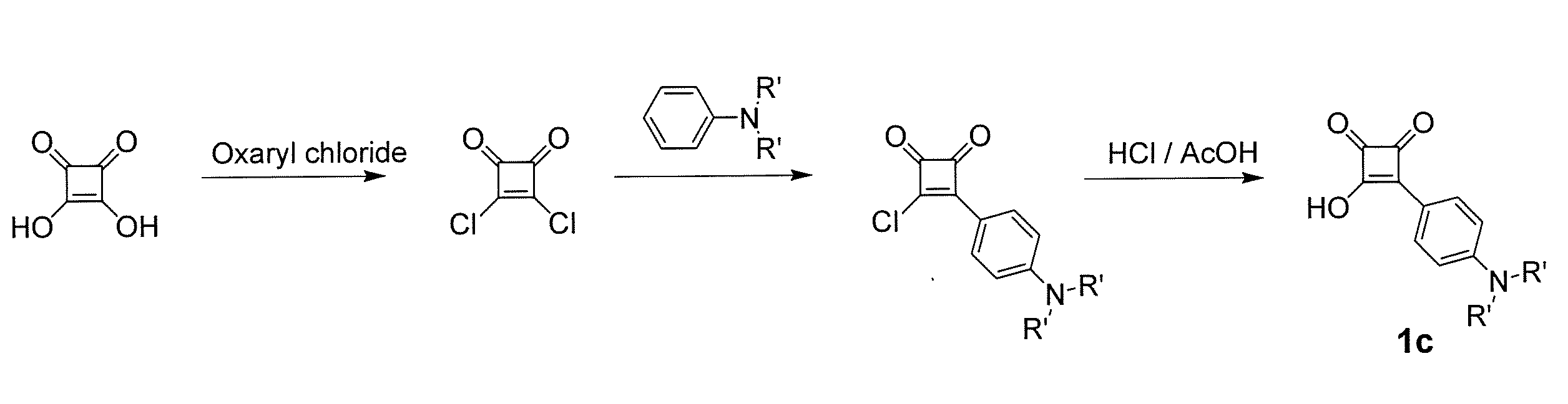
式(1)で表されるスクアリリウム色素の中間体であるアリール置換スクアリン酸(1c)は、スクアリン酸を用いて、J. Am. Chem. Soc., 2004, 126, 21, p6590-6598を参考に合成することができる。窒素上の置換基を変化させたアニリンやアミノナフタレン、アミノアントラセン、アミノフェナントレン等を使用することにより、種々のアリール置換スクアリン酸を合成することができる。R'はアルキル基もしくはフェニル基であり、R2を与える。
式(1)で表わされるスクアリリウム色素は、カルボキシ基又はエステル基を有するN-アルキル含窒素複素環塩(1b)とアリール置換スクアリン酸(1c)を用い、Dyes And Pigments, 11, 1989, p21-35を参考にして合成することができる。但し、R4がC1~C6のアルキル基の場合は、更に、水酸化ナトリウム等のアルカリを用いたアルカリ加水分解反応によりエステル基をカルボキシ基に変換することで、式(1)で表わされるスクアリリウム色素を合成することができる。

(R4は水素又はC1~C6のアルキル基を示す。)
式(1)で表わされるスクアリリウム色素は、比較的長波長側に吸収領域を持つという特徴を有する。そこで、これより短波長側に吸収領域を持つ他の色素を式(1)で表わさられるスクアリリウム色素と共に使用することにより、広い範囲の波長領域において光を吸収できるものとすることができる。上記他の色素は、400~580nmに最大吸収波長を有することがよい。
式(1)で表わされるスクアリリウム色素と、これより短波長側に吸収領域を持ち、400~580nmに最大吸収波長を有する他の色素(以下、短波長側色素ともいう。)を併用する場合、好ましい使用割合は前者/後者の重量比で0.3~10、より好ましくは1~4の範囲である。
上記短波長側色素は、有機色素であってもよく、また無機色素であってもよい。例えば、下記式(25)で表わされる色素がある。式(25)で表わされる色素は比較的短波長側に吸収領域を有するので、短波長領域における光電変換素子又は色素増感太陽電池用色素として優れる。

色素増感太陽電池は使用する光源によって、増感色素の吸収波長域を選ぶことができるが、式(1)、又は式(1)と式(25)で表わされる色素を使用し、必要により目的とする光源の波長域に合わせるように更に別の色素を選ぶこともできる。
2種以上の色素を使用する場合、これらは混合された状態で色素吸着金属酸化物層に吸着されて存在させるか、色素吸着金属酸化物層の厚み方向に色素が異なる層を形成するように吸着されて存在させることがよい。
色素は、色素吸着金属酸化物層に吸着されて存在するので、色素は金属酸化物からなる半導体微粒子の表面と結合する適当な官能基(interlocking group)を有していることが好ましい。好ましい官能基としては、-COOH基、-SO3H基、シアノ基、-P(O)(OH)2基、-OP(O)(OH)2基、-OH基又はオキシム、ジオキシム、ヒドロキシキノリン、サリチレート及びα-ケトエノレートのようなπ伝導性を有するキレート化基が挙げられる。これらの中でも-COOH基が好ましく、上記式(1)で表される色素は-COOH基を有する点でも好ましい。
本発明の色素を用いた光電変換素子又は色素増感太陽電池の基本構成の一例を図1により説明する。図1は光電変換素子の一例を示す断面図であり、基板1上に、透明導電膜2と、一つ以上の層で構成された半導体層に増感用の色素が吸着された表面電極10と、基板4上に導電膜5が設けられた対向電極11を有し、両電極間に電解質層6を配した構成となっている。ここで、基板1と透明導電膜2からなる層が導電性支持体であり、増感用の色素が吸着された半導体層が色素吸着金属酸化物層3である。
色素吸着金属酸化物層3は、電極の一部を構成するため半導体電極ともいう。色素吸着金属酸化物層3はチタニアあるいはその他の金属酸化物微粒子を用い1つの層として塗工・焼結されたもの、又は複数回の塗工・焼結により形成された層であり、色素が吸着された半導体層であり、酸化チタン粒子等の金属酸化物粒子とこの粒子の表面を覆うように存在する増感用の色素からなっている。なお、光は表面電極10側から入る。そして、本発明の色素増感太陽電池は、上記と同様な基本構成を有するが外部回路で仕事をさせるようにしたものである。そして、光電変換素子を色素増感太陽電池とする方法は公知の方法でよい。
基板1としては、透明な絶縁材料であれば特に限定されるものではなく、例えば通常のガラス板やプラスチック板などが挙げられ、更には屈曲性のあるものでも良く、例えばPET樹脂などが挙げられるが、好ましくは約500℃を上限にした酸化チタンを焼付ける工程に耐え得る耐熱材料であることであり、透明なガラス板が挙げられる。
次に、この基板1の表面に基材の透明性を損なわないような透明導電膜2を設けるが、具体的には、いわゆる透明電極として知られているITO、FTO、ATOあるいはこれらを組み合わせたものでよく、更には透明性を損なわない厚みの金属層であってもよい。これらの導電膜を設ける方法は特に限定されるものではなく、スパッタリング、蒸着(CVD及びPVDを含む)、スプレー、レーザアブレーションあるいはペースト化した各材料を用いるスピンコート、バーコート、スクリーン印刷の手法など既知の手法を用いることができる。中でも、スプレー法又は気相で行われるスパッタリング又は蒸着法が適する。
この上に、色素吸着金属酸化物層3を設ける。通常は半導体として金属酸化物の層を形成したのち、これに増感色素を吸着させる。金属酸化物としては、光電変換材料と知られているものが使用でき、酸化チタン、酸化亜鉛、酸化タングステン、等を挙げることができる、中でも酸化チタンが好ましい。酸化チタンとしては、アナターゼ型、ルチル型、ブルッカイト型等の酸化チタンの他、水酸化チタン、含水酸化チタン類であってもよい。また、Nb、V又はTaの各元素の少なくとも1つを酸化チタンに対して30ppm~5%の重量濃度(金属元素として)になるようドーピングしてもよい。このような金属酸化物であれば、本発明に用いることが可能であるが、平均粒子径が5~500nm、好ましくは10~200 nmの範囲の微粒子であることがよい。
金属酸化物の層を前記透明導電膜2上に形成するが、その方法については、特に限定されるものではなく、例えばペースト化した金属酸化物をスピンコート、印刷、スプレーコートなどの各手法を用いても良い。また、製膜後に酸化チタン等の金属酸化物の焼結などを目的に焼成することも可能である。次に、金属酸化物に増感用の色素を吸着させて色素吸着金属酸化物として、色素吸着金属酸化物層3とする。
本発明では増感色素に特徴があり、その他の層又は材料は公知の構造又は材料とすることができ、図1に示す構造のものに限らない。
色素吸着金属酸化物層3を構成する材料は、半導体となる金属酸化物と色素である。金属酸化物は、好ましくは酸化チタンであるので、金属酸化物を酸化チタンで代表することがある。また、色素増感用の色素としては、上記式(1)で表わされるスクアリリウム色素単独でもよく、他の色素と併用してもよい。
色素はこれを溶解する溶媒に溶解してチタニア半導体層のような金属酸化物層に吸着させる。吸着溶媒は色素が溶解可能である溶媒であれば、使用することができる。具体的には、メタノール、エタノール、プロパノール、ノルマルブタノール等の脂肪族アルコール類、アセトニトリル、プロピオニトリル等のニトリル溶媒、アセトン、メチルエチルケトン等のケトン類、ジメチルカーボネート、ジエチルカーボネート等のカーボネート類、ラクトン類、カプロラクタム類を使用することができる。好ましくはメタノール、エタノール又はアセトニトリルである。
色素を吸着させる方法としては、室温、加熱下又は還流下の色素溶液の中に金属酸化物層を浸漬し、色素を吸着する方法が一般的である。また、色素溶液にデオキシコール酸、ケノデオキシコール酸(DCA)等の共吸着剤を溶解した色素溶液を用い、吸着してもよい。
超臨界流体又は加圧流体を溶媒とし、色素をこれに溶解して吸着させてもよい。具体的には、超臨界炭酸ガス又は加圧炭酸ガスや炭酸ガスにエントレーナーを加えた溶媒に、色素を溶解させた溶液により吸着させることが好ましい。
複数の色素を使用する場合、複数の色素を溶媒に溶解して一つの溶液として金属酸化物層に吸着させる方法は、色素が混合された状態で吸着させた色素吸着金属酸化物層を得るために適する。また、複数の色素をそれぞれ別の溶媒に溶解して複数の溶液を作り、その溶液を順番に使用して金属酸化物層に吸着させる方法は、色素を厚み方向に層状に吸着させた色素吸着金属酸化物層を得るために適する。色素を層状に吸着させた色素吸着金属酸化物層は、例えば、第一の色素溶液に金属酸化物層を浸漬すると、表面側の金属酸化物層に色素が吸着され、次に第二の色素溶液に第一の色素が吸着された金属酸化物層を浸漬すると、第一の色素が吸着された層より内層側の金属酸化物層に色素が吸着される。必要によりこの操作を繰り返したり、第三の色素溶液を使用したりすれば、多層に色素が吸着された金属酸化物層が得られる。色素は順次金属酸化物層の表面側から吸着されるので、上記方法により有機色素を層状に吸着させた色素吸着金属酸化物層を得る場合は、色素溶液との接触時間や濃度を制御して各吸着層の厚みを調整する。この方法は、溶媒が超臨界炭酸ガス又は加圧炭酸ガス流体である場合や、超臨界炭酸ガス又は加圧炭酸ガスにエントレーナーを加えた溶媒である場合にも好適である。
色素の吸着した金属酸化物には、更にCO2超臨界流体中でカルボン酸を吸着させてもよい。カルボン酸を吸着させる効果は、文献J. Photochem. and Photobio. A, Chem., 164 (2004) 117により公知である。しかしながら、色素吸着やリンス処理と同様に、酸化チタンなどの金属酸化物の微細孔内部まで有効に吸着させることが重要である。色素の吸着した金属酸化物(色素の吸着した金属酸化物層を有する基板であってもよい)とカルボン酸を、圧力範囲5~30Mpaであり、温度範囲が40~60℃で形成されるCO2超臨界流体中又は加圧CO2中に置くことで、有効にカルボン酸を吸着できる。カルボン酸としては、好ましくは安息香酸、酢酸、アニス酸、ニコチン酸を挙げることができる。これらカルボン酸は、メタノール、エタノール、プロパノール、ブタノールのうちの少なくともいずれか1種類を含むアルコールに溶解した状態で使用することが好ましく、そのカルボン酸濃度が0.01~10mol/Lの範囲であることが好ましい。
上記のように基板1、透明導電膜2及び色素吸着金属酸化物層3からなる表面電極10は負極として作用する。もう一方の正極として作用する電極(対向電極)11は図1に示すように、表面電極10と対向して配置する。正極となる電極は、導電性の金属などでよく、また、例えば通常のガラス板やプラスチック板などの基板4に金属膜や炭素膜等の導電膜5を施したものでもよい。
負極となる表面電極10と、正極となる対向電極11の間には、電解質層6を設ける。この電解質の種類は、光励起され半導体への電子注入を果した後の色素を還元するための酸化還元種を含んでいれば特に限定されず、液状の電解質であってもよく、これに公知のゲル化剤(高分子又は低分子のゲル化剤)やイオン液体と金属酸化物を混練した擬固体を添加して得られるゲル状の電解質であってもよい。
また、溶液電解質に用いる電解質の例としては、ヨウ素とヨウ化物(LiI、NaI、KI、CsI、CaI2等の金属ヨウ化物、テトラアルキルアンモニウムヨーダイド、ピリジニウムヨーダイド、イミダゾリウムヨーダイド等の4級アンモニウム化合物ヨウ素塩等)の組み合わせ、臭素と臭化物(LiBr、NaBr、KBr、CsBr、CaBr2等の金属臭化物、テトラアルキルアンモニウムブロマイド、ピリジニウムブロマイド等の4級アンモニウム化合物臭素塩等)の組み合わせ、ポリ硫化ナトリウム、アルキルチオール、アルキルジスルフィド等のイオウ化合物、ビオロゲン色素、ヒドロキノン、キノン等が挙げられる。電解質は混合して用いてもよい。
また、電解質としては、高沸点を有する溶融塩電解質が好ましい。半導体電極が色素吸着酸化チタン層からなる場合は、溶融塩電解質と組み合わせることにより、特に優れた電池特性を発揮する。溶融塩電解質組成物は溶融塩を含む。溶融塩電解質組成物は常温で液体であるのが好ましい。主成分である溶融塩は室温において液状であるか又は低融点の電解質であり、その一般的な例としては「電気化学」、1997年、第65巻、第11号、p.923 等に記載のピリジニウム塩、イミダゾリウム塩、トリアゾリウム塩等が挙げられる。溶融塩は単独で使用しても2種以上混合して使用してもよい。また、LiI、NaI、KI、LiBF4、CF3COOLi、CF3COONa、LiSCN、NaSCN等のアルカリ金属塩を併用することもできる。通常、溶融塩電解質組成物はヨウ素を含有する。溶融塩電解質組成物の揮発性は低いことが好ましく、溶媒を含まないことが好ましい。溶融塩電解質組成物はゲル化して使用してもよい。
電解質に溶媒を使用する場合は、粘度が低く高イオン移動度を示し、優れたイオン伝導性を発現できる化合物であることが望ましい。このような溶媒の例としては、エチレンカーボネート、プロピレンカーボネート等のカーボネート化合物、3-メチル-2-オキサゾリジノン等の複素環化合物、ジオキサン、ジエチルエーテル等のエーテル化合物、エチレングリコールジアルキルエーテル、プロピレングリコールジアルキルエーテル、ポリエチレングリコールジアルキルエーテル、ポリプロピレングリコールジアルキルエーテル等の鎖状エーテル類、メタノール、エタノール、エチレングリコールモノアルキルエーテル、プロピレングリコールモノアルキルエーテル、ポリエチレングリコールモノアルキルエーテル、ポリプロピレングリコールモノアルキルエーテル等のアルコール類、エチレングリコール、プロピレングリコール、ポリエチレングリコール、ポリプロピレングリコール、グリセリン等の多価アルコール類、アセトニトリル、グルタロジニトリル、メトキシアセトニトリル、プロピオニトリル、ベンゾニトリル等のニトリル化合物、ジメチルスルホキシド、スルフォラン等の非プロトン極性物質、水等が挙げられる。これらの溶媒は混合して用いることもできる。
電解質層6を設ける方法は特に限定されるものではなく、例えば両電極の間にフィルム状のスペーサ7を配置して隙間を形成し、その隙間に電解質を注入する方法でも良く、また、負極内面に電解質を塗布などした後に正極を適当な間隔をおいて積載する方法でも良い。電解質が流出しないよう、両極とその周囲を封止することが望ましいが、封止の方法や封止材の材質については特に限定するものではない。
以下、合成例、実施例及び比較例に基づいて本発明について更に詳細に説明する。
実施例1
カルボキシインドレニン類(カルボキシ基を有する含窒素複素環類)は、4-ヒドラジノ安息香酸とメチルイソプロピルケトンの市販試薬を用い合成した。4-ヒドラジノ安息香酸78.87mmolと酢酸ソーダ160.92mmolとメチルイソプロピルケトン123.46mmolを氷酢酸180mlに加え窒素下で120℃、7時間攪拌して反応させる。反応終了後、酢酸を留去して得られる固形分を水:メタノール=9:1の溶液に分散させろ過する。固形分をメタノール70gに加え30℃に加温し、分散、溶解させ、不溶分をろ過する。ろ液に水160gを加え結晶化させ、ろ過する。得られた固形分を水:メタノール=9:1の溶液35mlで洗浄したのち、真空乾燥し、カルボキシインドレニン類(カルボキシ基を有する含窒素複素環類)として、37.7mmolの2,3,3‐トリメチル-5-カルボキシ-インドールを得た。
カルボキシインドレニン類(カルボキシ基を有する含窒素複素環類)は、4-ヒドラジノ安息香酸とメチルイソプロピルケトンの市販試薬を用い合成した。4-ヒドラジノ安息香酸78.87mmolと酢酸ソーダ160.92mmolとメチルイソプロピルケトン123.46mmolを氷酢酸180mlに加え窒素下で120℃、7時間攪拌して反応させる。反応終了後、酢酸を留去して得られる固形分を水:メタノール=9:1の溶液に分散させろ過する。固形分をメタノール70gに加え30℃に加温し、分散、溶解させ、不溶分をろ過する。ろ液に水160gを加え結晶化させ、ろ過する。得られた固形分を水:メタノール=9:1の溶液35mlで洗浄したのち、真空乾燥し、カルボキシインドレニン類(カルボキシ基を有する含窒素複素環類)として、37.7mmolの2,3,3‐トリメチル-5-カルボキシ-インドールを得た。
N-n-アルキルカルボキシインドレニン塩(カルボキシ基を有する含窒素複素環塩)の合成は、2,3,3‐トリメチル-5-カルボキシ-インドール10.21mmolと1-ヨウ化ドデカン43.89mmolを82mlのアセトニトリルに溶かし、還流しながら7日間反応させた。固形分をろ過し、酢酸エチルとアセトニトリルの混合溶液で再結晶し1-n-ドデシル-2,3,3-トリメチル-5-カルボキシ-インドレニウムアイオダイドを65%の収率で得た。
ジメチルアニリン置換スクアリン酸の合成は、以下のように行う。3,4-ジヒドロキシ-3-シクロブテン-1,2-ジオン90mmolを100mlのジクロロメタンに加え、反応容器を氷冷しながら、滴下ロートを用いて二塩化オキサリルを180mmol、10分かけて添加する。滴下終了後、還流しながら4時間攪拌して反応させる。反応終了後、ジクロロメタンを留去して真空乾燥し、白色結晶を90mmol得た。この白色結晶を26.5mmolとり、トルエン100mlに溶かして、N,N-ジメチルアニリン26.5mmolを加えて還流しながら6時間攪拌して反応させた。反応後、溶液を氷水にあけ、トルエンで抽出する。トルエンを留去して黒色の固体9.7mmolを得た。この黒色の固体に水25ml、酢酸25ml、一規定塩酸4mlを加えて2時間還流しながら攪拌して反応させる。室温まで冷却し、沈殿してきた固体をろ過してジエチルエーテルで洗浄し、ジメチルアニリン置換のスクアリン酸を5.8mmolを得た。
スクアリリウム色素の合成は、1-n-ドデシル-2,3,3-トリメチル-5-カルボキシ-インドレニウムアイオダイド5.5mmolとジメチルアニリン置換スクアリン酸5.5mmolを50mlのトルエン-ブタノール溶媒(トルエン/ブタノール容積比=1/1)に溶かし、水を除去しながら還流し3時間反応させた。室温に冷却し、溶媒を除去した後にシリカゲルカラムクロマトグラフィーにより精製し、スクアリリウム色素D-1を得た。スクアリリウム色素D-1のIRスペクトル、MSスペクトル及び1H-NMRスペクトル(溶媒:MeOH-d4)を測定した。IRスペクトル、及び1H-NMRスペクトルを、それぞれ図2、及び図3に示す。
実施例2
インドレニン塩を合成する際に、1-ヨードドデカンの変わりに1-ヨードヘキサンを使用する以外は実施例1と同様にしてスクアリリウム色素D-2を得た。
インドレニン塩を合成する際に、1-ヨードドデカンの変わりに1-ヨードヘキサンを使用する以外は実施例1と同様にしてスクアリリウム色素D-2を得た。
実施例3
インドレニン塩を合成する際に、1-ヨードドデカンの変わりに1-ヨードエイコサンを使用する以外は実施例1と同様にしてスクアリリウム色素D-3を得た。
インドレニン塩を合成する際に、1-ヨードドデカンの変わりに1-ヨードエイコサンを使用する以外は実施例1と同様にしてスクアリリウム色素D-3を得た。
実施例4
インドレニンを合成する際に、4-ヒドラジノ安息香酸の代わりに4-ヒドラジノ-1-カルボキシナフタレンを使用し、N-アルキルカルボキシインドレニン塩を合成する際に、1-ヨウ化ドデカンの代わりに、1-ヨードヘキサンを使用し、アリール置換スクアリン酸を合成する際に、N,N-ジメチルアニリンの代わりにN,N-ジオクチル-1-アミノアントラセンを使用する以外は実施例1と同様にしてスクアリリウム色素D-12を得た。
インドレニンを合成する際に、4-ヒドラジノ安息香酸の代わりに4-ヒドラジノ-1-カルボキシナフタレンを使用し、N-アルキルカルボキシインドレニン塩を合成する際に、1-ヨウ化ドデカンの代わりに、1-ヨードヘキサンを使用し、アリール置換スクアリン酸を合成する際に、N,N-ジメチルアニリンの代わりにN,N-ジオクチル-1-アミノアントラセンを使用する以外は実施例1と同様にしてスクアリリウム色素D-12を得た。
実施例5
アリール置換スクアリン酸を合成する際に、N,N-ジメチルアニリンの代わりにN,N-ジドデシルアニリンを使用する以外は実施例1と同様にしてスクアリリウム色素D-5を得た。
アリール置換スクアリン酸を合成する際に、N,N-ジメチルアニリンの代わりにN,N-ジドデシルアニリンを使用する以外は実施例1と同様にしてスクアリリウム色素D-5を得た。
実施例6
アリール置換スクアリン酸を合成する際に、N,N-ジメチルアニリンの代わりにN,N-ジメチルナフタレンを使用する以外は実施例1と同様にしてスクアリリウム色素D-10を得た。
アリール置換スクアリン酸を合成する際に、N,N-ジメチルアニリンの代わりにN,N-ジメチルナフタレンを使用する以外は実施例1と同様にしてスクアリリウム色素D-10を得た。
実施例7
インドレニンを合成する際に、4-ヒドラジノ安息香酸の代わりに4-ヒドラジノ-1-カルボキシナフタレンを使用し、N-アルキルカルボキシインドレニン塩を合成する際に、1-ヨウ化ドデカンの代わりに、1,1,1,2,2,3,3,4,4-ノナフルオロ-6-ヨードヘキサンを使用し、溶媒としてアセトニトリルの代わりに3-メトキシプロピオニトリルを使用し、アリール置換スクアリン酸を合成する際に、N,N-ジメチルアニリンの代わりにN,N-ジオクチル-1-アミノアントラセンを使用する以外は実施例1と同様にしてスクアリリウム色素D-11を得た。
インドレニンを合成する際に、4-ヒドラジノ安息香酸の代わりに4-ヒドラジノ-1-カルボキシナフタレンを使用し、N-アルキルカルボキシインドレニン塩を合成する際に、1-ヨウ化ドデカンの代わりに、1,1,1,2,2,3,3,4,4-ノナフルオロ-6-ヨードヘキサンを使用し、溶媒としてアセトニトリルの代わりに3-メトキシプロピオニトリルを使用し、アリール置換スクアリン酸を合成する際に、N,N-ジメチルアニリンの代わりにN,N-ジオクチル-1-アミノアントラセンを使用する以外は実施例1と同様にしてスクアリリウム色素D-11を得た。
実施例8
インドレニンを合成する際に、4-ヒドラジノ安息香酸の代わりに4-ヒドラジノ-1-カルボキシナフタレンを使用し、N-アルキルカルボキシインドレニン塩を合成する際に、1-ヨウ化ドデカンの代わりに、1,1,1-トリフルオロ-4-ヨードブタンを使用し、アリール置換スクアリン酸を合成する際に、N,N-ジメチルアニリンの代わりにN,N-ジオクチル-1-アミノアントラセンを使用する以外は実施例1と同様にしてスクアリリウム色素D-13を得た。
インドレニンを合成する際に、4-ヒドラジノ安息香酸の代わりに4-ヒドラジノ-1-カルボキシナフタレンを使用し、N-アルキルカルボキシインドレニン塩を合成する際に、1-ヨウ化ドデカンの代わりに、1,1,1-トリフルオロ-4-ヨードブタンを使用し、アリール置換スクアリン酸を合成する際に、N,N-ジメチルアニリンの代わりにN,N-ジオクチル-1-アミノアントラセンを使用する以外は実施例1と同様にしてスクアリリウム色素D-13を得た。
比較例1
インドレニン塩を合成する際に、1-ヨードドデカンの変わりに1-ヨウ化ブタンを使用する以外は実施例1と同様にしてスクアリリウム色素D-4を得た。
インドレニン塩を合成する際に、1-ヨードドデカンの変わりに1-ヨウ化ブタンを使用する以外は実施例1と同様にしてスクアリリウム色素D-4を得た。
比較例2
N-アルキルカルボキシインドレニン塩を合成する際に、1-ヨードドデカンの代わりに1-ヨードエタンを使用する以外は実施例1と同様にしてスクアリリウム色素D-6を得た。
N-アルキルカルボキシインドレニン塩を合成する際に、1-ヨードドデカンの代わりに1-ヨードエタンを使用する以外は実施例1と同様にしてスクアリリウム色素D-6を得た。
比較例3
N-アルキルカルボキシインドレニン塩を合成する際に、1-ヨードドデカンの代わりに1-ヨードテトラコサンを使用する以外は実施例1と同様にしてスクアリリウム色素D-7を得た。
N-アルキルカルボキシインドレニン塩を合成する際に、1-ヨードドデカンの代わりに1-ヨードテトラコサンを使用する以外は実施例1と同様にしてスクアリリウム色素D-7を得た。
比較例4
インドレニンを合成する際に、4-ヒドラジノ安息香酸の代わりにフェニルヒドラジンを、メチルイソプロピルケトンの代わりに3-ブチル-2-ヘプタノンを使用し、N-アルキルカルボキシインドレニン塩を合成する際に、1-ヨードドデカンの代わりに3-ヨードプロピオン酸を使用する以外は実施例1と同様にしてスクアリリウム色素D-8を得た。
インドレニンを合成する際に、4-ヒドラジノ安息香酸の代わりにフェニルヒドラジンを、メチルイソプロピルケトンの代わりに3-ブチル-2-ヘプタノンを使用し、N-アルキルカルボキシインドレニン塩を合成する際に、1-ヨードドデカンの代わりに3-ヨードプロピオン酸を使用する以外は実施例1と同様にしてスクアリリウム色素D-8を得た。
比較例5
アリール置換スクアリン酸を合成する際に、N,N-ジメチルアニリンの代わりにN,N-ジヘキサデカニルアニリンを使用する以外は実施例1と同様にしてスクアリリウム色素D-9を得た。
アリール置換スクアリン酸を合成する際に、N,N-ジメチルアニリンの代わりにN,N-ジヘキサデカニルアニリンを使用する以外は実施例1と同様にしてスクアリリウム色素D-9を得た。
実施例1~8及び比較例1~5で得たスクアリリウム色素D-1~D-9の化学式を一般式(26)で示し、X、R1、A及びR2を表12に示すことにより、特定する。また、これらの色素及びD-149の最大吸収波長、吸収端、吸着溶液を作る際のエタノールに対する溶解性を表11に示す。溶解性については、良好なものを○、加熱作業等が必要なものを△、難溶性なものを×で示した。なお、D-149の化学式は上記式(25)で表される。


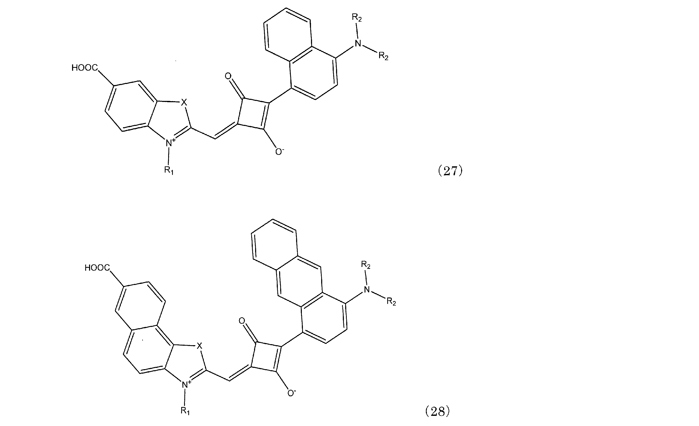
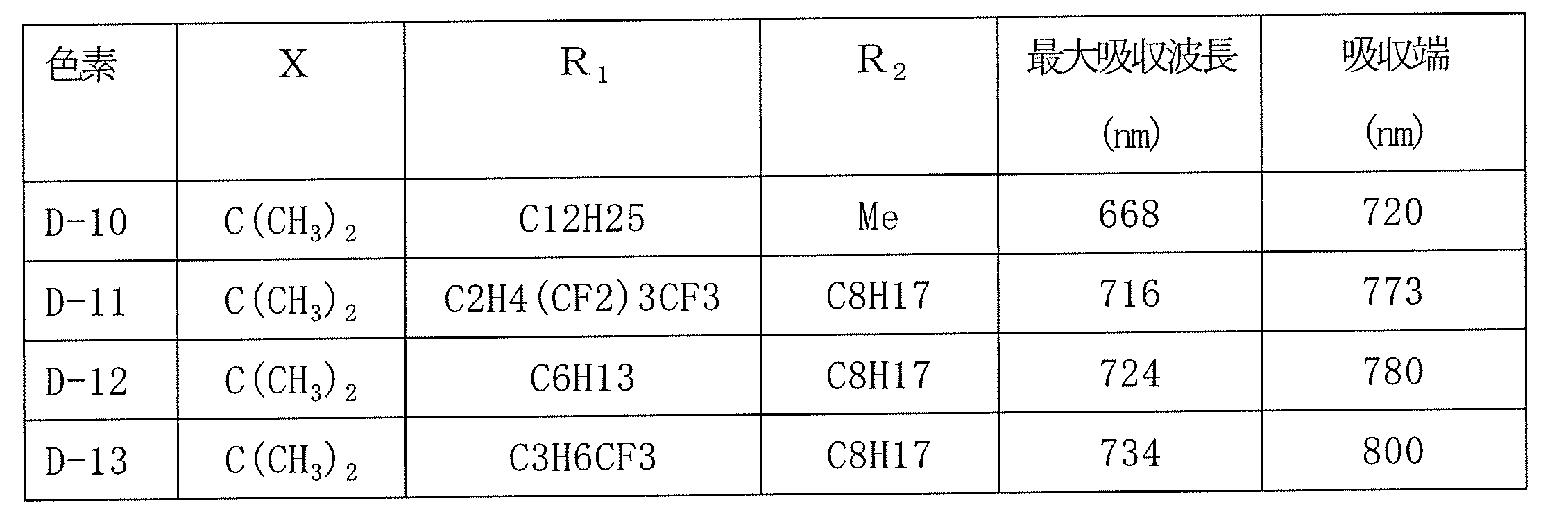
スクアリリウム色素D-10の化学式を一般式(27)で示し、D-11~13の化学式を一般式(28)で示し、X、R1及びR2を表13に示すことにより、特定する。最大吸収波長及び吸収端を表12に示す。
実施例9
30mm×25mm×3mmの透明導電膜付ガラス基板として日本板ガラス製のFTO(フッ素ドープ酸化スズ)膜付ガラス基板(商品名:Low‐Eガラス)を使用した。 次に、導電性膜付き基板の導電性膜上に、酸化チタン膜を形成した。酸化チタンは、市販の酸化チタンペースト(ソラロニクス社製Dペースト)を使用した。これを、導電性膜付き基板の導電性膜上に、スキージ印刷の手法で5mm×5mmの範囲に塗工し、乾燥後450℃で焼成して厚み15μmの酸化チタン層を形成した積層板を得た。
30mm×25mm×3mmの透明導電膜付ガラス基板として日本板ガラス製のFTO(フッ素ドープ酸化スズ)膜付ガラス基板(商品名:Low‐Eガラス)を使用した。 次に、導電性膜付き基板の導電性膜上に、酸化チタン膜を形成した。酸化チタンは、市販の酸化チタンペースト(ソラロニクス社製Dペースト)を使用した。これを、導電性膜付き基板の導電性膜上に、スキージ印刷の手法で5mm×5mmの範囲に塗工し、乾燥後450℃で焼成して厚み15μmの酸化チタン層を形成した積層板を得た。
色素としてD-1を使用した。これを2.5×10⁻⁴mol/L、DCAを2.5×10-2mol/Lとなるようにエタノールに溶解させた。色素の吸着は浸漬法により行った。具体的には、溶媒に溶かし溶液を作成し、容器に色素溶液を入れ、更に上記酸化チタン層を形成した積層板を配置し、浸漬、吸着させた後、容器から色素の吸着した積層板を取り出した。
この積層板の酸化チタンの膜を形成した5mm×5mmの外周4辺に厚み50μmのアイオノマー樹脂からなるシート状の熱可塑性接着剤(三井デュポンポリケミカル社商品名;ハイミランシート)を、電解質が注入できるよう、外周部の2箇所に約1mm程度の隙間を設けるようにして貼り付けた。この熱可塑性接着剤は、封止材であると同時に、両極間のスペーサの役割を果たす。次に、正極となる厚み10nmの白金膜をスパッタリングの手法で形成したガラス基板を、白金側が酸化チタン側と対向するように前記熱可塑性接着剤フィルムを介して貼り合わせた。この熱可塑性接着剤フィルムの隙間から、0.5MのLiI、0.5Mのt-ブチルピリジンと、0.05Mのヨウ素を主成分として含むアセトニトリル溶液を毛細管現象を利用して基材と正極の間に満たした。電解質を満たした後、直ちに前記隙間をエポキシ樹脂接着剤で封止して、光電変換素子を得た。
実施例10
色素D-1に代えて色素D-2を使用した他は、実施例9と同様にして光電変換素子を得た。
色素D-1に代えて色素D-2を使用した他は、実施例9と同様にして光電変換素子を得た。
実施例11
色素D-1を2.5×10⁻⁴mol/L、色素D‐149を0.75×10-4mol/Lそれぞれエタノールに溶かし、さらにDCAを3.0x10-3mol/Lとなるように溶かした2種類の色素溶液に順次吸着させる、色素層状浸漬法による色素吸着を行った他は、実施例9と同様にして光電変換素子を得た。
色素D-1を2.5×10⁻⁴mol/L、色素D‐149を0.75×10-4mol/Lそれぞれエタノールに溶かし、さらにDCAを3.0x10-3mol/Lとなるように溶かした2種類の色素溶液に順次吸着させる、色素層状浸漬法による色素吸着を行った他は、実施例9と同様にして光電変換素子を得た。
実施例12
色素D-1に代えて色素D-3を使用した他は、実施例9と同様にして光電変換素子を得た。
色素D-1に代えて色素D-3を使用した他は、実施例9と同様にして光電変換素子を得た。
比較例10
色素D-1に代えて色素D-4を使用した他は、実施例9と同様にして光電変換素子を得た。
色素D-1に代えて色素D-4を使用した他は、実施例9と同様にして光電変換素子を得た。
実施例14
色素D-1に代えて色素D-5を使用した他は、実施例9と同様にして光電変換素子を得た。
色素D-1に代えて色素D-5を使用した他は、実施例9と同様にして光電変換素子を得た。
実施例15
色素D-1に代えて色素D-10を使用した他は、実施例9と同様にして光電変換素子を得た。
色素D-1に代えて色素D-10を使用した他は、実施例9と同様にして光電変換素子を得た。
実施例16
色素D-1に代えて色素D-11を使用した他は、実施例9と同様にして光電変換素子を得た。
色素D-1に代えて色素D-11を使用した他は、実施例9と同様にして光電変換素子を得た。
実施例17
色素D-1に代えて色素D-13を使用した他は、実施例9と同様にして光電変換素子を得た。
色素D-1に代えて色素D-13を使用した他は、実施例9と同様にして光電変換素子を得た。
比較例7
色素D-1に代えて色素D-6を使用した他は、実施例9と同様にして光電変換素子を得た。
色素D-1に代えて色素D-6を使用した他は、実施例9と同様にして光電変換素子を得た。
比較例7
色素D-1に代えて色素D-7を使用した他は、実施例9と同様にして光電変換素子を得た。
色素D-1に代えて色素D-7を使用した他は、実施例9と同様にして光電変換素子を得た。
比較例8
色素D-1に代えて色素D-8を使用した他は、実施例9と同様にして光電変換素子を得た。
色素D-1に代えて色素D-8を使用した他は、実施例9と同様にして光電変換素子を得た。
比較例9
色素D-1に代えて色素D-9を使用した他は、実施例9と同様にして光電変換素子を得た。
色素D-1に代えて色素D-9を使用した他は、実施例9と同様にして光電変換素子を得た。
実施例13
色素D-1に代えて色素D-12を使用した他は、実施例9と同様にして光電変換素子を得た。
色素D-1に代えて色素D-12を使用した他は、実施例9と同様にして光電変換素子を得た。
比較例11
色素D-1に代えて色素D-149を使用した他は、実施例9と同様にして光電変換素子を得た。
色素D-1に代えて色素D-149を使用した他は、実施例9と同様にして光電変換素子を得た。
実施例及び比較例で作成した光電変換素子を色素増感太陽電池として、その電池特性をソーラーシミュレータを用いて測定した。測定はAM1.5、100mW/cm2の擬似太陽光を用い、I-Vカーブトレーサーを用いて特性評価した。変換効率(%)を測定した結果を表13に示す。IPCE(Incident-Photon-to-Current conversion Efficiency)、分光感度測定装置を使用し、波長ごとの量子収率を測定したものである。なお、表中、IPCE-1は短波長側色素最大吸収波長(nm)であり、IPCE-2は長波長側色素最大吸収波長(nm)である。また、色素1は、短波長側色素であり、色素2は、長波長側色素である。色素吸着法において、Dは浸漬法であり、LDは色素層状浸漬法である。

本発明のスクアリリウム化合物は、光電変換素子又は色素増感太陽電池に使用される増感色素であるスクアリリウム色素として有用である。このスクアリリウム色素を使用した光電変換素子又は色素増感太陽電池は、近赤外光領域における光電変換効率が高い。また、式(1)で表されるスクアリリウム化合物と共に、それより短波長側で光を吸収する色素を用いることにより、高価なRu色素を使うことなく、2つの色素の相乗効果により光電変換効率がより向上する。また、本発明のスクアリリウム色素は光電変換効率が高い光電変換素子又はこれから構成した色素増感太陽電池を与える。
Claims (9)
- 下記式(1)で表されることを特徴とするスクアリリウム化合物。
式(1)において、Y及びZは各々独立して、炭素原子とともに5又は6員環を含有する環構造を形成する原子団を表す。A1及びA2は各々独立して、水素又はカルボキシル基を表し、A1及びA2のうち少なくとも一つは5又は6員環に結合するカルボキシル基である。XはC(CH3)2、S、Se又はNR3を表し、R3は水素又はC1~C15のアルキル基を示す。R1はC5~C20のアルキル基又はCF3(CF2)m(CH2)nで表されるフッ素置換アルキル基であり、mとnは独立に0~14の整数を表すが、2≦m+n<15である。R2はC1~C15のアルキル基もしくはフェニル基を示す。
- 式(1)において、Zにより形成される環構造が、ピロール、インドレニン、ベンゾインドレニン、ナフトインドレニン、ピリミジン、ピラゾール、イミダゾール、ピラン、ピラジン又はピリダジンの環構造である請求項1に記載のスクアリリウム化合物。
- 式(1)において、Yにより形成される環構造が、ベンゼン、ナフタレン、アントラセン、フェナントレン、テトラセン、クリセン、トリフェニレン、テトラフェン、ピレン、ペンタセン、ピセン又はペリレンの環構造である請求項1に記載のスクアリリウム化合物。
- 下記式(2)で表されることを特徴とする請求項1に記載のスクアリリウム化合物。
式(2)において、R1はC5~C20のアルキル基であり、R2はC1~C15のアルキル基もしくはフェニル基を示す。
- 下記式(3)で表されることを特徴とする請求項1に記載のスクアリリウム化合物。
式(3)において、R1はC5~C20のアルキル基である。R2はC1~C15のアルキル基もしくはフェニル基を示す。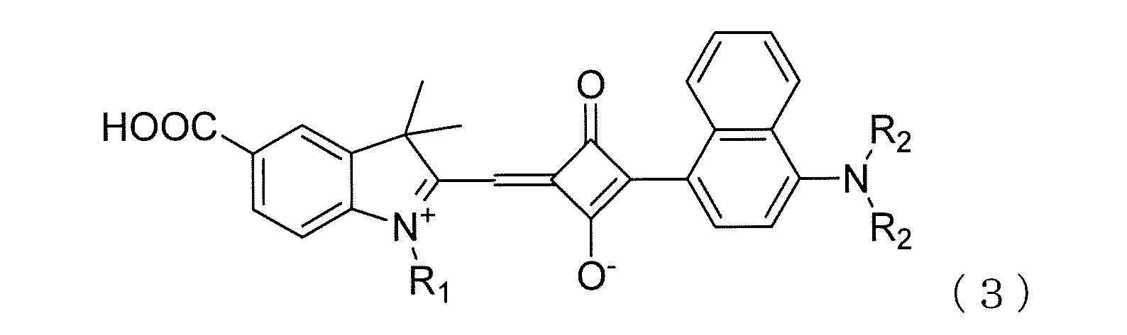
- 下記式(4)で表されることを特徴とする請求項1に記載のスクアリリウム化合物。
式(4)において、Z1は、隣接する含窒素環とともにインドレニン、ベンゾインドレニン又はナフトインドレニンの環構造を形成する原子団を表す。Y1は、炭素原子とともにベンゼン、ナフタレン又はアントラセンの環構造を形成する原子団を表す。R1はCF3(CF2)m(CH2)nで表されるフッ素置換アルキル基であり、mとnは独立に0~14の整数を表すが、2≦m+n<15である。R2はC1~C15のアルキル基もしくはフェニル基を示す。
- 少なくとも色素によって増感された色素吸着金属酸化物層を有する光電変換素子又は色素増感光太陽電池用の色素において、色素が請求項1~6のいずれかに記載のスクアリリウム化合物からなることを特徴とする光電変換素子又は色素増感光太陽電池用のスクアリリウム色素。
- 少なくとも色素によって増感された色素吸着金属酸化物層を有する光電変換素子において、該色素が請求項7に記載のスクアリリウム色素を含むことを特徴とする光電変換素子。
- 少なくとも色素によって増感された色素吸着金属酸化物層を有する色素増感太陽電池において、該色素が請求項7に記載のスクアリリウム色素を含むことを特徴とする色素増感太陽電池。
Priority Applications (1)
| Application Number | Priority Date | Filing Date | Title |
|---|---|---|---|
| JP2012503092A JP5875511B2 (ja) | 2010-03-02 | 2011-02-24 | スクアリリウム色素、これを使用する光電変換素子及び色素増感太陽電池 |
Applications Claiming Priority (4)
| Application Number | Priority Date | Filing Date | Title |
|---|---|---|---|
| JP2010045439 | 2010-03-02 | ||
| JP2010-045439 | 2010-03-02 | ||
| JP2010191892 | 2010-08-30 | ||
| JP2010-191892 | 2010-08-30 |
Publications (1)
| Publication Number | Publication Date |
|---|---|
| WO2011108432A1 true WO2011108432A1 (ja) | 2011-09-09 |
Family
ID=44542086
Family Applications (1)
| Application Number | Title | Priority Date | Filing Date |
|---|---|---|---|
| PCT/JP2011/054107 Ceased WO2011108432A1 (ja) | 2010-03-02 | 2011-02-24 | スクアリリウム色素、これを使用する光電変換素子及び色素増感太陽電池 |
Country Status (3)
| Country | Link |
|---|---|
| JP (1) | JP5875511B2 (ja) |
| TW (1) | TWI537342B (ja) |
| WO (1) | WO2011108432A1 (ja) |
Cited By (1)
| Publication number | Priority date | Publication date | Assignee | Title |
|---|---|---|---|---|
| JP2013199536A (ja) * | 2012-03-23 | 2013-10-03 | Nippon Steel & Sumikin Chemical Co Ltd | ポリメチン色素前駆体、その前駆体の骨格を含むスクアリリウム色素、それを用いた色素増感太陽電池、光電変換素子 |
Families Citing this family (1)
| Publication number | Priority date | Publication date | Assignee | Title |
|---|---|---|---|---|
| CN114773875B (zh) * | 2022-03-15 | 2023-09-12 | 大连理工大学 | 一类氮杂吲哚-方酸菁染料,其合成方法及应用 |
Citations (2)
| Publication number | Priority date | Publication date | Assignee | Title |
|---|---|---|---|---|
| JP2006265549A (ja) * | 2005-02-28 | 2006-10-05 | Sumitomo Chemical Co Ltd | 色素化合物、該化合物を用いた光電変換素子及び光電気化学電池 |
| JP2010027281A (ja) * | 2008-07-16 | 2010-02-04 | Kyoto Univ | 広帯域波長領域の光電変換を可能にする太陽電池 |
Family Cites Families (1)
| Publication number | Priority date | Publication date | Assignee | Title |
|---|---|---|---|---|
| JPH03235959A (ja) * | 1990-02-13 | 1991-10-21 | Konica Corp | 電子写真感光体 |
-
2011
- 2011-02-24 WO PCT/JP2011/054107 patent/WO2011108432A1/ja not_active Ceased
- 2011-02-24 JP JP2012503092A patent/JP5875511B2/ja not_active Expired - Fee Related
- 2011-02-24 TW TW100106208A patent/TWI537342B/zh not_active IP Right Cessation
Patent Citations (2)
| Publication number | Priority date | Publication date | Assignee | Title |
|---|---|---|---|---|
| JP2006265549A (ja) * | 2005-02-28 | 2006-10-05 | Sumitomo Chemical Co Ltd | 色素化合物、該化合物を用いた光電変換素子及び光電気化学電池 |
| JP2010027281A (ja) * | 2008-07-16 | 2010-02-04 | Kyoto Univ | 広帯域波長領域の光電変換を可能にする太陽電池 |
Cited By (1)
| Publication number | Priority date | Publication date | Assignee | Title |
|---|---|---|---|---|
| JP2013199536A (ja) * | 2012-03-23 | 2013-10-03 | Nippon Steel & Sumikin Chemical Co Ltd | ポリメチン色素前駆体、その前駆体の骨格を含むスクアリリウム色素、それを用いた色素増感太陽電池、光電変換素子 |
Also Published As
| Publication number | Publication date |
|---|---|
| TW201141956A (en) | 2011-12-01 |
| TWI537342B (zh) | 2016-06-11 |
| JP5875511B2 (ja) | 2016-03-02 |
| JPWO2011108432A1 (ja) | 2013-06-27 |
Similar Documents
| Publication | Publication Date | Title |
|---|---|---|
| JP5527620B2 (ja) | 色素増感太陽電池、光電変換素子及びそれに使用される色素 | |
| JP4841248B2 (ja) | 色素増感光電変換素子 | |
| EP2315303B1 (en) | Dye-sensitized photovoltaic device | |
| KR20130082489A (ko) | 신규한 티오펜계 염료 및 이의 제조방법 | |
| JP2008021496A (ja) | 色素増感光電変換素子 | |
| JP5725459B2 (ja) | スクアリリウム色素及びそれらの色素を用いた色素増感太陽電池、光電変換素子 | |
| JP2013030320A (ja) | 光電変換素子、光電気化学電池、及びそれらに用いられる色素 | |
| JP5846579B2 (ja) | ポリメチン色素前駆体、その前駆体の骨格を含むスクアリリウム色素、それを用いた色素増感太陽電池、光電変換素子 | |
| JP5875511B2 (ja) | スクアリリウム色素、これを使用する光電変換素子及び色素増感太陽電池 | |
| CN103748097B (zh) | 高电导性的空穴传输材料以及利用其的染料敏化太阳能电池 | |
| JP2002334729A (ja) | 色素増感光電変換素子 | |
| JP5392765B2 (ja) | 光電変換素子用の色素、光電変換素子及び色素増感太陽電池 | |
| KR100996236B1 (ko) | 신규한 루테늄계 염료 및 이의 제조방법 | |
| JP4230182B2 (ja) | 色素増感光電変換素子及びこれを用いた太陽電池 | |
| KR20100128096A (ko) | 신규한 루테늄계 염료 및 이의 제조방법 | |
| JP2004022387A (ja) | 色素増感光電変換素子 | |
| KR20100128258A (ko) | 신규한 루테늄계 염료 및 이의 제조방법 | |
| KR20100128094A (ko) | 신규한 줄로리딘계 염료 및 이의 제조방법 | |
| JP5906522B2 (ja) | フタロシアニン色素並びにフタロシアニン色素を用いた色素増感太陽電池及び光電変換素子 | |
| JP5906489B2 (ja) | ポルフィリン色素並びにポルフィリン色素を用いた色素増感太陽電池及び光電変換素子 | |
| JP5906521B2 (ja) | フタロシアニン色素並びにフタロシアニン色素を用いた色素増感太陽電池及び光電変換素子 | |
| JP2015180718A (ja) | フタロシアニン色素、これを用いた色素増感太陽電池及び光電変換素子 | |
| JP2013112702A (ja) | 光電変換素子用のスクアリリウム色素、これを使用する光電変換素子及び色素増感太陽電池 | |
| JP2012204284A (ja) | シアニン色素並びにシアニン色素を用いた色素増感太陽電池及び光電変換素子 | |
| JP2012201864A (ja) | シアニン色素、これを用いた色素増感太陽電池及び光電変換素子 |
Legal Events
| Date | Code | Title | Description |
|---|---|---|---|
| 121 | Ep: the epo has been informed by wipo that ep was designated in this application |
Ref document number: 11750542 Country of ref document: EP Kind code of ref document: A1 |
|
| WWE | Wipo information: entry into national phase |
Ref document number: 2012503092 Country of ref document: JP |
|
| NENP | Non-entry into the national phase |
Ref country code: DE |
|
| 122 | Ep: pct application non-entry in european phase |
Ref document number: 11750542 Country of ref document: EP Kind code of ref document: A1 |