WO2011108070A1 - 動力伝達制御装置 - Google Patents
動力伝達制御装置 Download PDFInfo
- Publication number
- WO2011108070A1 WO2011108070A1 PCT/JP2010/053280 JP2010053280W WO2011108070A1 WO 2011108070 A1 WO2011108070 A1 WO 2011108070A1 JP 2010053280 W JP2010053280 W JP 2010053280W WO 2011108070 A1 WO2011108070 A1 WO 2011108070A1
- Authority
- WO
- WIPO (PCT)
- Prior art keywords
- torque
- correction value
- power source
- power transmission
- clutch
- Prior art date
Links
Images


Classifications
-
- B—PERFORMING OPERATIONS; TRANSPORTING
- B60—VEHICLES IN GENERAL
- B60K—ARRANGEMENT OR MOUNTING OF PROPULSION UNITS OR OF TRANSMISSIONS IN VEHICLES; ARRANGEMENT OR MOUNTING OF PLURAL DIVERSE PRIME-MOVERS IN VEHICLES; AUXILIARY DRIVES FOR VEHICLES; INSTRUMENTATION OR DASHBOARDS FOR VEHICLES; ARRANGEMENTS IN CONNECTION WITH COOLING, AIR INTAKE, GAS EXHAUST OR FUEL SUPPLY OF PROPULSION UNITS IN VEHICLES
- B60K6/00—Arrangement or mounting of plural diverse prime-movers for mutual or common propulsion, e.g. hybrid propulsion systems comprising electric motors and internal combustion engines ; Control systems therefor, i.e. systems controlling two or more prime movers, or controlling one of these prime movers and any of the transmission, drive or drive units Informative references: mechanical gearings with secondary electric drive F16H3/72; arrangements for handling mechanical energy structurally associated with the dynamo-electric machine H02K7/00; machines comprising structurally interrelated motor and generator parts H02K51/00; dynamo-electric machines not otherwise provided for in H02K see H02K99/00
- B60K6/20—Arrangement or mounting of plural diverse prime-movers for mutual or common propulsion, e.g. hybrid propulsion systems comprising electric motors and internal combustion engines ; Control systems therefor, i.e. systems controlling two or more prime movers, or controlling one of these prime movers and any of the transmission, drive or drive units Informative references: mechanical gearings with secondary electric drive F16H3/72; arrangements for handling mechanical energy structurally associated with the dynamo-electric machine H02K7/00; machines comprising structurally interrelated motor and generator parts H02K51/00; dynamo-electric machines not otherwise provided for in H02K see H02K99/00 the prime-movers consisting of electric motors and internal combustion engines, e.g. HEVs
- B60K6/42—Arrangement or mounting of plural diverse prime-movers for mutual or common propulsion, e.g. hybrid propulsion systems comprising electric motors and internal combustion engines ; Control systems therefor, i.e. systems controlling two or more prime movers, or controlling one of these prime movers and any of the transmission, drive or drive units Informative references: mechanical gearings with secondary electric drive F16H3/72; arrangements for handling mechanical energy structurally associated with the dynamo-electric machine H02K7/00; machines comprising structurally interrelated motor and generator parts H02K51/00; dynamo-electric machines not otherwise provided for in H02K see H02K99/00 the prime-movers consisting of electric motors and internal combustion engines, e.g. HEVs characterised by the architecture of the hybrid electric vehicle
- B60K6/48—Parallel type
-
- B—PERFORMING OPERATIONS; TRANSPORTING
- B60—VEHICLES IN GENERAL
- B60W—CONJOINT CONTROL OF VEHICLE SUB-UNITS OF DIFFERENT TYPE OR DIFFERENT FUNCTION; CONTROL SYSTEMS SPECIALLY ADAPTED FOR HYBRID VEHICLES; ROAD VEHICLE DRIVE CONTROL SYSTEMS FOR PURPOSES NOT RELATED TO THE CONTROL OF A PARTICULAR SUB-UNIT
- B60W20/00—Control systems specially adapted for hybrid vehicles
- B60W20/10—Controlling the power contribution of each of the prime movers to meet required power demand
-
- B—PERFORMING OPERATIONS; TRANSPORTING
- B60—VEHICLES IN GENERAL
- B60K—ARRANGEMENT OR MOUNTING OF PROPULSION UNITS OR OF TRANSMISSIONS IN VEHICLES; ARRANGEMENT OR MOUNTING OF PLURAL DIVERSE PRIME-MOVERS IN VEHICLES; AUXILIARY DRIVES FOR VEHICLES; INSTRUMENTATION OR DASHBOARDS FOR VEHICLES; ARRANGEMENTS IN CONNECTION WITH COOLING, AIR INTAKE, GAS EXHAUST OR FUEL SUPPLY OF PROPULSION UNITS IN VEHICLES
- B60K6/00—Arrangement or mounting of plural diverse prime-movers for mutual or common propulsion, e.g. hybrid propulsion systems comprising electric motors and internal combustion engines ; Control systems therefor, i.e. systems controlling two or more prime movers, or controlling one of these prime movers and any of the transmission, drive or drive units Informative references: mechanical gearings with secondary electric drive F16H3/72; arrangements for handling mechanical energy structurally associated with the dynamo-electric machine H02K7/00; machines comprising structurally interrelated motor and generator parts H02K51/00; dynamo-electric machines not otherwise provided for in H02K see H02K99/00
- B60K6/20—Arrangement or mounting of plural diverse prime-movers for mutual or common propulsion, e.g. hybrid propulsion systems comprising electric motors and internal combustion engines ; Control systems therefor, i.e. systems controlling two or more prime movers, or controlling one of these prime movers and any of the transmission, drive or drive units Informative references: mechanical gearings with secondary electric drive F16H3/72; arrangements for handling mechanical energy structurally associated with the dynamo-electric machine H02K7/00; machines comprising structurally interrelated motor and generator parts H02K51/00; dynamo-electric machines not otherwise provided for in H02K see H02K99/00 the prime-movers consisting of electric motors and internal combustion engines, e.g. HEVs
- B60K6/22—Arrangement or mounting of plural diverse prime-movers for mutual or common propulsion, e.g. hybrid propulsion systems comprising electric motors and internal combustion engines ; Control systems therefor, i.e. systems controlling two or more prime movers, or controlling one of these prime movers and any of the transmission, drive or drive units Informative references: mechanical gearings with secondary electric drive F16H3/72; arrangements for handling mechanical energy structurally associated with the dynamo-electric machine H02K7/00; machines comprising structurally interrelated motor and generator parts H02K51/00; dynamo-electric machines not otherwise provided for in H02K see H02K99/00 the prime-movers consisting of electric motors and internal combustion engines, e.g. HEVs characterised by apparatus, components or means specially adapted for HEVs
- B60K6/38—Arrangement or mounting of plural diverse prime-movers for mutual or common propulsion, e.g. hybrid propulsion systems comprising electric motors and internal combustion engines ; Control systems therefor, i.e. systems controlling two or more prime movers, or controlling one of these prime movers and any of the transmission, drive or drive units Informative references: mechanical gearings with secondary electric drive F16H3/72; arrangements for handling mechanical energy structurally associated with the dynamo-electric machine H02K7/00; machines comprising structurally interrelated motor and generator parts H02K51/00; dynamo-electric machines not otherwise provided for in H02K see H02K99/00 the prime-movers consisting of electric motors and internal combustion engines, e.g. HEVs characterised by apparatus, components or means specially adapted for HEVs characterised by the driveline clutches
- B60K6/387—Actuated clutches, i.e. clutches engaged or disengaged by electric, hydraulic or mechanical actuating means
-
- B—PERFORMING OPERATIONS; TRANSPORTING
- B60—VEHICLES IN GENERAL
- B60W—CONJOINT CONTROL OF VEHICLE SUB-UNITS OF DIFFERENT TYPE OR DIFFERENT FUNCTION; CONTROL SYSTEMS SPECIALLY ADAPTED FOR HYBRID VEHICLES; ROAD VEHICLE DRIVE CONTROL SYSTEMS FOR PURPOSES NOT RELATED TO THE CONTROL OF A PARTICULAR SUB-UNIT
- B60W10/00—Conjoint control of vehicle sub-units of different type or different function
- B60W10/02—Conjoint control of vehicle sub-units of different type or different function including control of driveline clutches
-
- B—PERFORMING OPERATIONS; TRANSPORTING
- B60—VEHICLES IN GENERAL
- B60W—CONJOINT CONTROL OF VEHICLE SUB-UNITS OF DIFFERENT TYPE OR DIFFERENT FUNCTION; CONTROL SYSTEMS SPECIALLY ADAPTED FOR HYBRID VEHICLES; ROAD VEHICLE DRIVE CONTROL SYSTEMS FOR PURPOSES NOT RELATED TO THE CONTROL OF A PARTICULAR SUB-UNIT
- B60W10/00—Conjoint control of vehicle sub-units of different type or different function
- B60W10/04—Conjoint control of vehicle sub-units of different type or different function including control of propulsion units
- B60W10/06—Conjoint control of vehicle sub-units of different type or different function including control of propulsion units including control of combustion engines
-
- B—PERFORMING OPERATIONS; TRANSPORTING
- B60—VEHICLES IN GENERAL
- B60W—CONJOINT CONTROL OF VEHICLE SUB-UNITS OF DIFFERENT TYPE OR DIFFERENT FUNCTION; CONTROL SYSTEMS SPECIALLY ADAPTED FOR HYBRID VEHICLES; ROAD VEHICLE DRIVE CONTROL SYSTEMS FOR PURPOSES NOT RELATED TO THE CONTROL OF A PARTICULAR SUB-UNIT
- B60W10/00—Conjoint control of vehicle sub-units of different type or different function
- B60W10/04—Conjoint control of vehicle sub-units of different type or different function including control of propulsion units
- B60W10/08—Conjoint control of vehicle sub-units of different type or different function including control of propulsion units including control of electric propulsion units, e.g. motors or generators
-
- B—PERFORMING OPERATIONS; TRANSPORTING
- B60—VEHICLES IN GENERAL
- B60W—CONJOINT CONTROL OF VEHICLE SUB-UNITS OF DIFFERENT TYPE OR DIFFERENT FUNCTION; CONTROL SYSTEMS SPECIALLY ADAPTED FOR HYBRID VEHICLES; ROAD VEHICLE DRIVE CONTROL SYSTEMS FOR PURPOSES NOT RELATED TO THE CONTROL OF A PARTICULAR SUB-UNIT
- B60W10/00—Conjoint control of vehicle sub-units of different type or different function
- B60W10/10—Conjoint control of vehicle sub-units of different type or different function including control of change-speed gearings
-
- B—PERFORMING OPERATIONS; TRANSPORTING
- B60—VEHICLES IN GENERAL
- B60W—CONJOINT CONTROL OF VEHICLE SUB-UNITS OF DIFFERENT TYPE OR DIFFERENT FUNCTION; CONTROL SYSTEMS SPECIALLY ADAPTED FOR HYBRID VEHICLES; ROAD VEHICLE DRIVE CONTROL SYSTEMS FOR PURPOSES NOT RELATED TO THE CONTROL OF A PARTICULAR SUB-UNIT
- B60W20/00—Control systems specially adapted for hybrid vehicles
-
- B—PERFORMING OPERATIONS; TRANSPORTING
- B60—VEHICLES IN GENERAL
- B60K—ARRANGEMENT OR MOUNTING OF PROPULSION UNITS OR OF TRANSMISSIONS IN VEHICLES; ARRANGEMENT OR MOUNTING OF PLURAL DIVERSE PRIME-MOVERS IN VEHICLES; AUXILIARY DRIVES FOR VEHICLES; INSTRUMENTATION OR DASHBOARDS FOR VEHICLES; ARRANGEMENTS IN CONNECTION WITH COOLING, AIR INTAKE, GAS EXHAUST OR FUEL SUPPLY OF PROPULSION UNITS IN VEHICLES
- B60K6/00—Arrangement or mounting of plural diverse prime-movers for mutual or common propulsion, e.g. hybrid propulsion systems comprising electric motors and internal combustion engines ; Control systems therefor, i.e. systems controlling two or more prime movers, or controlling one of these prime movers and any of the transmission, drive or drive units Informative references: mechanical gearings with secondary electric drive F16H3/72; arrangements for handling mechanical energy structurally associated with the dynamo-electric machine H02K7/00; machines comprising structurally interrelated motor and generator parts H02K51/00; dynamo-electric machines not otherwise provided for in H02K see H02K99/00
- B60K6/20—Arrangement or mounting of plural diverse prime-movers for mutual or common propulsion, e.g. hybrid propulsion systems comprising electric motors and internal combustion engines ; Control systems therefor, i.e. systems controlling two or more prime movers, or controlling one of these prime movers and any of the transmission, drive or drive units Informative references: mechanical gearings with secondary electric drive F16H3/72; arrangements for handling mechanical energy structurally associated with the dynamo-electric machine H02K7/00; machines comprising structurally interrelated motor and generator parts H02K51/00; dynamo-electric machines not otherwise provided for in H02K see H02K99/00 the prime-movers consisting of electric motors and internal combustion engines, e.g. HEVs
- B60K6/22—Arrangement or mounting of plural diverse prime-movers for mutual or common propulsion, e.g. hybrid propulsion systems comprising electric motors and internal combustion engines ; Control systems therefor, i.e. systems controlling two or more prime movers, or controlling one of these prime movers and any of the transmission, drive or drive units Informative references: mechanical gearings with secondary electric drive F16H3/72; arrangements for handling mechanical energy structurally associated with the dynamo-electric machine H02K7/00; machines comprising structurally interrelated motor and generator parts H02K51/00; dynamo-electric machines not otherwise provided for in H02K see H02K99/00 the prime-movers consisting of electric motors and internal combustion engines, e.g. HEVs characterised by apparatus, components or means specially adapted for HEVs
- B60K6/26—Arrangement or mounting of plural diverse prime-movers for mutual or common propulsion, e.g. hybrid propulsion systems comprising electric motors and internal combustion engines ; Control systems therefor, i.e. systems controlling two or more prime movers, or controlling one of these prime movers and any of the transmission, drive or drive units Informative references: mechanical gearings with secondary electric drive F16H3/72; arrangements for handling mechanical energy structurally associated with the dynamo-electric machine H02K7/00; machines comprising structurally interrelated motor and generator parts H02K51/00; dynamo-electric machines not otherwise provided for in H02K see H02K99/00 the prime-movers consisting of electric motors and internal combustion engines, e.g. HEVs characterised by apparatus, components or means specially adapted for HEVs characterised by the motors or the generators
- B60K2006/268—Electric drive motor starts the engine, i.e. used as starter motor
-
- B—PERFORMING OPERATIONS; TRANSPORTING
- B60—VEHICLES IN GENERAL
- B60K—ARRANGEMENT OR MOUNTING OF PROPULSION UNITS OR OF TRANSMISSIONS IN VEHICLES; ARRANGEMENT OR MOUNTING OF PLURAL DIVERSE PRIME-MOVERS IN VEHICLES; AUXILIARY DRIVES FOR VEHICLES; INSTRUMENTATION OR DASHBOARDS FOR VEHICLES; ARRANGEMENTS IN CONNECTION WITH COOLING, AIR INTAKE, GAS EXHAUST OR FUEL SUPPLY OF PROPULSION UNITS IN VEHICLES
- B60K6/00—Arrangement or mounting of plural diverse prime-movers for mutual or common propulsion, e.g. hybrid propulsion systems comprising electric motors and internal combustion engines ; Control systems therefor, i.e. systems controlling two or more prime movers, or controlling one of these prime movers and any of the transmission, drive or drive units Informative references: mechanical gearings with secondary electric drive F16H3/72; arrangements for handling mechanical energy structurally associated with the dynamo-electric machine H02K7/00; machines comprising structurally interrelated motor and generator parts H02K51/00; dynamo-electric machines not otherwise provided for in H02K see H02K99/00
- B60K6/20—Arrangement or mounting of plural diverse prime-movers for mutual or common propulsion, e.g. hybrid propulsion systems comprising electric motors and internal combustion engines ; Control systems therefor, i.e. systems controlling two or more prime movers, or controlling one of these prime movers and any of the transmission, drive or drive units Informative references: mechanical gearings with secondary electric drive F16H3/72; arrangements for handling mechanical energy structurally associated with the dynamo-electric machine H02K7/00; machines comprising structurally interrelated motor and generator parts H02K51/00; dynamo-electric machines not otherwise provided for in H02K see H02K99/00 the prime-movers consisting of electric motors and internal combustion engines, e.g. HEVs
- B60K6/42—Arrangement or mounting of plural diverse prime-movers for mutual or common propulsion, e.g. hybrid propulsion systems comprising electric motors and internal combustion engines ; Control systems therefor, i.e. systems controlling two or more prime movers, or controlling one of these prime movers and any of the transmission, drive or drive units Informative references: mechanical gearings with secondary electric drive F16H3/72; arrangements for handling mechanical energy structurally associated with the dynamo-electric machine H02K7/00; machines comprising structurally interrelated motor and generator parts H02K51/00; dynamo-electric machines not otherwise provided for in H02K see H02K99/00 the prime-movers consisting of electric motors and internal combustion engines, e.g. HEVs characterised by the architecture of the hybrid electric vehicle
- B60K6/48—Parallel type
- B60K2006/4825—Electric machine connected or connectable to gearbox input shaft
-
- B—PERFORMING OPERATIONS; TRANSPORTING
- B60—VEHICLES IN GENERAL
- B60W—CONJOINT CONTROL OF VEHICLE SUB-UNITS OF DIFFERENT TYPE OR DIFFERENT FUNCTION; CONTROL SYSTEMS SPECIALLY ADAPTED FOR HYBRID VEHICLES; ROAD VEHICLE DRIVE CONTROL SYSTEMS FOR PURPOSES NOT RELATED TO THE CONTROL OF A PARTICULAR SUB-UNIT
- B60W50/00—Details of control systems for road vehicle drive control not related to the control of a particular sub-unit, e.g. process diagnostic or vehicle driver interfaces
- B60W2050/0062—Adapting control system settings
- B60W2050/0075—Automatic parameter input, automatic initialising or calibrating means
-
- B—PERFORMING OPERATIONS; TRANSPORTING
- B60—VEHICLES IN GENERAL
- B60W—CONJOINT CONTROL OF VEHICLE SUB-UNITS OF DIFFERENT TYPE OR DIFFERENT FUNCTION; CONTROL SYSTEMS SPECIALLY ADAPTED FOR HYBRID VEHICLES; ROAD VEHICLE DRIVE CONTROL SYSTEMS FOR PURPOSES NOT RELATED TO THE CONTROL OF A PARTICULAR SUB-UNIT
- B60W2510/00—Input parameters relating to a particular sub-units
- B60W2510/02—Clutches
- B60W2510/0241—Clutch slip, i.e. difference between input and output speeds
-
- B—PERFORMING OPERATIONS; TRANSPORTING
- B60—VEHICLES IN GENERAL
- B60W—CONJOINT CONTROL OF VEHICLE SUB-UNITS OF DIFFERENT TYPE OR DIFFERENT FUNCTION; CONTROL SYSTEMS SPECIALLY ADAPTED FOR HYBRID VEHICLES; ROAD VEHICLE DRIVE CONTROL SYSTEMS FOR PURPOSES NOT RELATED TO THE CONTROL OF A PARTICULAR SUB-UNIT
- B60W2510/00—Input parameters relating to a particular sub-units
- B60W2510/02—Clutches
- B60W2510/0258—Clutch friction coefficient
-
- B—PERFORMING OPERATIONS; TRANSPORTING
- B60—VEHICLES IN GENERAL
- B60W—CONJOINT CONTROL OF VEHICLE SUB-UNITS OF DIFFERENT TYPE OR DIFFERENT FUNCTION; CONTROL SYSTEMS SPECIALLY ADAPTED FOR HYBRID VEHICLES; ROAD VEHICLE DRIVE CONTROL SYSTEMS FOR PURPOSES NOT RELATED TO THE CONTROL OF A PARTICULAR SUB-UNIT
- B60W2510/00—Input parameters relating to a particular sub-units
- B60W2510/02—Clutches
- B60W2510/0275—Clutch torque
-
- B—PERFORMING OPERATIONS; TRANSPORTING
- B60—VEHICLES IN GENERAL
- B60W—CONJOINT CONTROL OF VEHICLE SUB-UNITS OF DIFFERENT TYPE OR DIFFERENT FUNCTION; CONTROL SYSTEMS SPECIALLY ADAPTED FOR HYBRID VEHICLES; ROAD VEHICLE DRIVE CONTROL SYSTEMS FOR PURPOSES NOT RELATED TO THE CONTROL OF A PARTICULAR SUB-UNIT
- B60W2510/00—Input parameters relating to a particular sub-units
- B60W2510/08—Electric propulsion units
- B60W2510/081—Speed
-
- B—PERFORMING OPERATIONS; TRANSPORTING
- B60—VEHICLES IN GENERAL
- B60W—CONJOINT CONTROL OF VEHICLE SUB-UNITS OF DIFFERENT TYPE OR DIFFERENT FUNCTION; CONTROL SYSTEMS SPECIALLY ADAPTED FOR HYBRID VEHICLES; ROAD VEHICLE DRIVE CONTROL SYSTEMS FOR PURPOSES NOT RELATED TO THE CONTROL OF A PARTICULAR SUB-UNIT
- B60W2510/00—Input parameters relating to a particular sub-units
- B60W2510/08—Electric propulsion units
- B60W2510/083—Torque
-
- B—PERFORMING OPERATIONS; TRANSPORTING
- B60—VEHICLES IN GENERAL
- B60W—CONJOINT CONTROL OF VEHICLE SUB-UNITS OF DIFFERENT TYPE OR DIFFERENT FUNCTION; CONTROL SYSTEMS SPECIALLY ADAPTED FOR HYBRID VEHICLES; ROAD VEHICLE DRIVE CONTROL SYSTEMS FOR PURPOSES NOT RELATED TO THE CONTROL OF A PARTICULAR SUB-UNIT
- B60W2510/00—Input parameters relating to a particular sub-units
- B60W2510/10—Change speed gearings
- B60W2510/1015—Input shaft speed, e.g. turbine speed
-
- B—PERFORMING OPERATIONS; TRANSPORTING
- B60—VEHICLES IN GENERAL
- B60W—CONJOINT CONTROL OF VEHICLE SUB-UNITS OF DIFFERENT TYPE OR DIFFERENT FUNCTION; CONTROL SYSTEMS SPECIALLY ADAPTED FOR HYBRID VEHICLES; ROAD VEHICLE DRIVE CONTROL SYSTEMS FOR PURPOSES NOT RELATED TO THE CONTROL OF A PARTICULAR SUB-UNIT
- B60W2510/00—Input parameters relating to a particular sub-units
- B60W2510/10—Change speed gearings
- B60W2510/1025—Input torque
-
- B—PERFORMING OPERATIONS; TRANSPORTING
- B60—VEHICLES IN GENERAL
- B60W—CONJOINT CONTROL OF VEHICLE SUB-UNITS OF DIFFERENT TYPE OR DIFFERENT FUNCTION; CONTROL SYSTEMS SPECIALLY ADAPTED FOR HYBRID VEHICLES; ROAD VEHICLE DRIVE CONTROL SYSTEMS FOR PURPOSES NOT RELATED TO THE CONTROL OF A PARTICULAR SUB-UNIT
- B60W2556/00—Input parameters relating to data
- B60W2556/10—Historical data
-
- B—PERFORMING OPERATIONS; TRANSPORTING
- B60—VEHICLES IN GENERAL
- B60W—CONJOINT CONTROL OF VEHICLE SUB-UNITS OF DIFFERENT TYPE OR DIFFERENT FUNCTION; CONTROL SYSTEMS SPECIALLY ADAPTED FOR HYBRID VEHICLES; ROAD VEHICLE DRIVE CONTROL SYSTEMS FOR PURPOSES NOT RELATED TO THE CONTROL OF A PARTICULAR SUB-UNIT
- B60W2710/00—Output or target parameters relating to a particular sub-units
- B60W2710/02—Clutches
- B60W2710/027—Clutch torque
-
- B—PERFORMING OPERATIONS; TRANSPORTING
- B60—VEHICLES IN GENERAL
- B60W—CONJOINT CONTROL OF VEHICLE SUB-UNITS OF DIFFERENT TYPE OR DIFFERENT FUNCTION; CONTROL SYSTEMS SPECIALLY ADAPTED FOR HYBRID VEHICLES; ROAD VEHICLE DRIVE CONTROL SYSTEMS FOR PURPOSES NOT RELATED TO THE CONTROL OF A PARTICULAR SUB-UNIT
- B60W2710/00—Output or target parameters relating to a particular sub-units
- B60W2710/08—Electric propulsion units
- B60W2710/083—Torque
-
- Y—GENERAL TAGGING OF NEW TECHNOLOGICAL DEVELOPMENTS; GENERAL TAGGING OF CROSS-SECTIONAL TECHNOLOGIES SPANNING OVER SEVERAL SECTIONS OF THE IPC; TECHNICAL SUBJECTS COVERED BY FORMER USPC CROSS-REFERENCE ART COLLECTIONS [XRACs] AND DIGESTS
- Y02—TECHNOLOGIES OR APPLICATIONS FOR MITIGATION OR ADAPTATION AGAINST CLIMATE CHANGE
- Y02T—CLIMATE CHANGE MITIGATION TECHNOLOGIES RELATED TO TRANSPORTATION
- Y02T10/00—Road transport of goods or passengers
- Y02T10/60—Other road transportation technologies with climate change mitigation effect
- Y02T10/62—Hybrid vehicles
Definitions
- the present invention relates to a mechanical power source that generates a driving force using mechanical energy as a power, an electric power source that generates a driving force using mechanical energy converted from electric energy, and the mechanical power source and the electric power source.
- a vehicle having a power connection / disconnection device having an engaging part capable of connecting / disconnecting power transmission between the power source and a fluid coupling that enables power transmission between the mechanical power source or the electric power source and the transmission
- the present invention relates to a power transmission control device.
- a drive control apparatus for a hybrid vehicle in which a clutch is provided between an engine as a mechanical power source and a motor as an electric power source, and the rotation of the motor is transmitted to the engine by engagement of the clutch, whereby the engine Japanese Patent Application Laid-Open Publication No. 2004-228561 discloses a technique for starting the system.
- this drive control device when the engine is started from a state where only the motor power (motor power running torque) is traveling (so-called EV traveling), the clutch is engaged, and the torque capacity of the clutch at that time is determined. Only the motor power running torque is increased.
- This drive control device reduces the driving force associated with the engagement of the clutch, that is, suppresses the reduction (deceleration) of the vehicle speed associated with the engagement of the clutch by the increased amount of the motor power running torque. To reduce the torque shock.
- an object of the present invention is to provide a power transmission control device that can improve the disadvantages of the conventional example and perform the MG torque compensation with high accuracy.
- the present invention provides at least one of a mechanical power source for generating a driving force by using mechanical energy as a power and an electric power source for generating a driving force by using mechanical energy converted from electric energy.
- a power connecting / disconnecting device having an engaging portion capable of connecting / disconnecting power transmission between the mechanical power source and the electric power source on a power transmission path capable of transmitting the power of the motor to the drive wheel side; And a fluid coupling that enables power transmission between the power source and / or the electric power source and the transmission, and engages the power connection / disconnection device during rotation of the rotating shaft of the electric power source.
- a torque compensation amount by the electric power source is set based on the estimated torque capacity of the power connection / disconnection device, and includes the torque compensation amount.
- the power of the electric power source In the vehicle power transmission control device for suppressing torque fluctuation on the power transmission path due to the engagement of the force connection / disconnection device, the torque capacity or the torque compensation amount is corrected based on the input torque of the fluid coupling. It is said.
- the difference between the input torque of the fluid coupling and the torque of the electric power source including the torque compensation amount is a correction value for the torque capacity or the torque compensation amount.
- the correction value obtained based on the input torque of the fluid coupling is a correction value for the torque capacity or the torque compensation amount at the next start of the mechanical power source.
- a correction value corresponding to the degree of progress of the engagement control of the power connection / disconnection device is obtained based on the input torque of the fluid coupling, and the correction value is calculated based on the torque capacity at the next start of the mechanical power source or the It is desirable to use a correction value for the torque compensation amount.
- a correction value corresponding to the degree of progress of the engagement control of the power connection / disconnection device is obtained based on the input torque of the fluid coupling, and the next time the mechanical power source is started based on all or a plurality of the correction values. It is desirable to obtain a correction value for the torque capacity or the torque compensation amount.
- a correction value corresponding to the degree of progress of the engagement control of the power connection / disconnection device is obtained based on the input torque of the fluid coupling, and the characteristic value of the power connection / disconnection device is corrected based on the correction value, It is desirable to estimate the torque capacity using the corrected characteristic value. At this time, it is preferable to obtain a correction value for the characteristic value of the power connection / disconnection device based on a correction value corresponding to the degree of progress of the engagement control of the power connection / disconnection device.
- the power transmission control device Since the power transmission control device according to the present invention corrects the torque capacity or the torque compensation amount based on the input torque of the fluid coupling, the torque compensation by the electric power source can be performed with an appropriate torque compensation amount. Further, the power transmission control device uses the correction value obtained based on the input torque of the fluid coupling or the correction value obtained based on the correction value as a correction value for the torque capacity or torque compensation amount at the next start of the mechanical power source. Thus, variation due to an estimation error in torque capacity is reduced, and appropriate torque compensation can be performed at the next start of the mechanical power source.
- the power transmission control device obtains a correction value corresponding to the degree of progress of engagement control of the power connection / disconnection device based on the input torque of the fluid coupling, and the correction value obtained based on the correction value or the correction value. Is also used as a correction value for the torque capacity or torque compensation amount at the start of the next mechanical power source, thereby reducing variations due to the estimation error of the torque capacity according to the degree of progress, and at the next start of the mechanical power source. Appropriate torque compensation can be performed.
- the power transmission control device corrects the characteristic value of the power connection / disconnection device based on the correction value corresponding to the degree of progress of the engagement control of the power connection / disconnection device, and uses the corrected characteristic value. Also, by estimating the torque capacity, the variation due to the estimation error of the torque capacity according to the degree of progress is reduced, and appropriate torque compensation can be performed at the next start of the mechanical power source.
- FIG. 1 is a diagram illustrating an example of a power transmission control device according to the present invention and a vehicle to which the power transmission control device is applied.
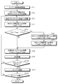
- FIG. 2 is a flowchart for explaining the engine starting operation.
- FIG. 3 is a time chart illustrating an example of the relationship among the engine speed, the target MG torque, the estimated AT input torque, and the estimated clutch torque capacity when the engine is started according to the first embodiment.
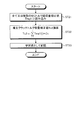
- FIG. 4 is a flowchart illustrating the learning control operation of the estimated clutch torque capacity correction value according to the second embodiment.
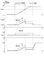
- FIG. 5 is a time chart showing an example of the relationship among the engine speed, the target MG torque, the estimated AT input torque, and the estimated clutch torque capacity when the engine is started according to the second embodiment.
- FIG. 1 is a diagram illustrating an example of a power transmission control device according to the present invention and a vehicle to which the power transmission control device is applied.
- FIG. 2 is a flowchart for explaining the engine starting operation.
- FIG. 3 is a time chart
- FIG. 6 is a flowchart illustrating the learning control operation of the friction coefficient correction value according to the third embodiment.
- FIG. 7 is a time chart illustrating an example of the relationship among the engine speed, the target MG torque, the estimated AT input torque, and the estimated clutch torque capacity when the engine is started according to the third embodiment.
- FIG. 8 is a diagram illustrating an example of the friction coefficient map data.
- a power transmission control device includes at least one of a mechanical power source that generates a driving force using mechanical energy as a power and an electric power source that generates a driving force using mechanical energy converted from electric energy as power.
- a power connecting / disconnecting device having an engaging portion capable of connecting / disconnecting power transmission between the mechanical power source and the electric power source on a power transmission path capable of transmitting power to the drive wheel side; And / or a fluid coupling that enables power transmission between the electric power source and the transmission, and engages the power connection / disconnection device during rotation of the rotating shaft of the electric power source to When starting the mechanical power source with the power of the source, set the torque compensation amount by the electric power source based on the estimated torque capacity of the power connection / disconnection device, and connect / disconnect the power with the power of the electric power source including the torque compensation amount Power transmission path accompanying device engagement It is intended to suppress the torque variation.
- the power transmission control device corrects the torque capacity or the torque compensation amount based on the input torque of the fluid coupling.
- Embodiments of a power transmission control device according to the present invention will be described below in detail with reference to the drawings. The present invention is not limited to the embodiments.
- Example 1 A power transmission control device according to a first embodiment of the present invention will be described with reference to FIGS.
- the reference numeral 1 in FIG. 1 transmits a mechanical power source driven by mechanical energy, an electric power source driven by mechanical energy converted from electric energy, and the power of the mechanical power source or the electric power source is transmitted to the drive wheels.
- the power transmission system according to the first embodiment includes a power connection / disconnection device capable of connecting / disconnecting power transmission between the mechanical power source and the electric power source, and between the mechanical power source and / or the electric power source and the transmission. And a fluid coupling that enables the transmission of power.
- the hybrid vehicle 1 includes an engine 10 that outputs mechanical power (engine torque) from an output shaft (crankshaft) 11 as a mechanical power source.
- the engine 10 may be an internal combustion engine, an external combustion engine, or the like.
- the operation of the engine 10 is controlled by an engine control unit of an engine electronic control device (hereinafter referred to as “engine ECU”) 101.
- engine ECU engine electronic control device
- the engine 10 is provided with a rotation sensor (a so-called crank angle sensor 12) that detects the rotation angle position of the output shaft 11, and the crank angle sensor 12 transmits a detection signal to the engine ECU 101.
- the hybrid vehicle 1 includes a motor, a generator capable of powering driving, or a motor / generator capable of driving both powering and regeneration as an electric power source.
- the motor / generator 20 will be described as an example.
- the motor / generator 20 is configured, for example, as a permanent magnet AC synchronous motor, and its operation is controlled by a motor / generator electronic control device (hereinafter referred to as “motor / generator ECU”) 102. .
- motor / generator ECU motor / generator electronic control device
- it functions as a motor (electric motor), converts electrical energy supplied from a battery (not shown) into mechanical energy, and outputs mechanical power (motor power running torque) from a rotary shaft 22 coaxial with the rotor 21. To do.
- regenerative drive it functions as a generator (generator) and converts mechanical energy into electrical energy when mechanical power (motor regenerative torque) is input from the rotary shaft 22, and via an inverter (not shown). Stores in battery as electric power.
- the motor / generator 20 is provided with a rotation sensor (resolver 23) that detects the rotational angle position of the rotor 21 (rotating shaft 22), and the resolver 23 transmits a detection signal to the motor / generator ECU 102.
- the hybrid vehicle 1 is provided with a power transmission system that transmits the power (engine torque and motor power running torque) of the engine 10 and the motor / generator 20 to the drive wheels WL and WR as a driving force.
- the power transmission system can transmit at least one power of the engine 10 and the motor / generator 20 to the drive wheels WL and WR, and constitutes a power transmission path.
- This power transmission system includes a power connection / disconnection device between the engine 10 and the motor / generator 20.
- the power connection / disconnection device connects and disconnects torque between the engine 10 and the drive wheels WL and WR, and transmits torque between the engine 10 and the motor / generator 20. It is also what makes you connect and disconnect. For this reason, the power connection / disconnection device engages the output shaft 11 of the engine 10 and the rotating shaft 22 of the motor / generator 20 and releases (disengages) them from the engagement state. Switching between the released state (non-engaged state) is enabled.
- this power connection / disconnection device is a so-called friction clutch device, and the engagement state and the release state are adjusted by adjusting the distance between the first engagement portion 31 and the second engagement portion 32 arranged to face each other.
- a switching clutch 30 is used.
- the clutch 30 connects the first engagement portion 31 so as to rotate integrally with the output shaft 11, and connects the second engagement portion 32 so as to rotate integrally with the rotation shaft 22.
- the clutch 30 is brought into an engaged state in which the first engaging portion 31 and the second engaging portion 32 are pressure-bonded by shortening the interval between them, and the output shaft 11 and the rotating shaft 22 are connected.
- the engagement state is a state corresponding to the pressure-bonding force between the first engagement portion 31 and the second engagement portion 32, and a half-engagement state in which slippage occurs between the first engagement portion 31 and the second engagement portion 32.
- the clutch 30 includes an elastic portion (not shown) that generates an elastic force as the distance between the first engagement portion 31 and the second engagement portion 32 decreases, for example, and the force in the crimping direction therebetween is When the elastic force of the elastic portion is below, the first engagement portion 31 and the second engagement portion 32 are in a released state in which they are separated from each other.
- the clutch 30 is operated by an actuator 40, and its operation is controlled by an electronic control unit for clutch (hereinafter referred to as “clutch ECU”) 103.
- the actuator 40 changes the interval between the first engaging portion 31 and the second engaging portion 32 and the pressure-bonding force at the time of engagement (that is, the engagement state) according to the amount of engagement control.
- the actuator 40 adjusts the engagement control amount, and lowers the force in the crimping direction according to the engagement control amount below the elastic force, thereby bringing the clutch 30 into a released state.
- the actuator 40 of the first embodiment is assumed to be operated by a working fluid.
- the pressure of the working fluid becomes the engagement control amount.
- the actuator 40 includes a working fluid supply device 41 and a clutch drive device 42.
- the working fluid supply device 41 includes an electric pump 41b that pumps the working fluid by the driving force of the motor 41a, and a working fluid channel 41c that sends the working fluid to the clutch driving device 42.
- the clutch drive device 42 includes an engagement control amount adjustment unit that adjusts the pressure of the working fluid supplied from the working fluid supply device 41 to a target pressure (target engagement control amount), and an adjusted target.
- a clutch drive unit that operates the clutch 30 in accordance with the pressure and adjusts the above-described distance and the pressure-bonding force (engagement state) at the time of engagement.
- a flow rate adjusting valve capable of adjusting the pressure by adjusting the flow rate of the working fluid may be used.
- the working fluid supply device 41 also includes a working fluid flow path 41d for working fluid to the automatic transmission 50 described later.
- the working fluid supply device 41 is controlled by the hybrid ECU 100 described later.
- the hybrid ECU 100 has a working fluid supplied from the working fluid supply device 41 at least higher than the target pressure (target engagement control amount) of the working fluid in the clutch 30 and the target pressure of the working fluid in the automatic transmission 50. Supply.
- a working oil such as ATF (Automatic Transmission Fluid) may be used.
- the hydraulic pressure of the hydraulic oil adjusted by the engagement control amount adjusting unit becomes the clutch engagement hydraulic pressure as the engagement control amount of the actuator 40.
- the engagement control amount adjusting unit of the clutch drive device 42 becomes unnecessary.
- the pressure of the working fluid supplied from the working fluid supply device 41 by the clutch ECU 103 may be adjusted to the target pressure (target engagement control amount).
- the power transmission system is a transmission that changes the rotation speed (torque) between input and output in accordance with a gear ratio, and includes a stepped transmission to which the power of the engine 10 and / or the motor / generator 20 is input.
- the stepped automatic transmission 50 is illustrated.
- the automatic transmission 50 can transmit power between a transmission main body 51 including gear groups and the like that form respective gear stages, and an input shaft 50a to which power is input and a gear group of the transmission main body 51.
- a torque converter 55 as a fluid coupling.
- the input shaft 50a is connected to the rotating shaft 22 of the motor / generator 20 so as to rotate integrally.
- the transmission main body 51 is provided with a plurality of known shift clutches (sometimes referred to as brakes) 52 that are connected and disconnected at the time of shifting gears to make a combination of gear groups corresponding to the gear to be controlled. Yes.
- the speed change clutch 52 is operated by the pressure of the supplied working fluid, and is capable of transmitting power from the engine 10 and / or the motor / generator 20 to the gear according to the shift speed to be controlled. And switch.
- the speed change clutch 52 includes a first engagement portion 52a and a second engagement portion 52b that are arranged to face each other, and the interval between the first engagement portion 52a and the second engagement portion 52b is supplied from the working fluid supply device 41. For example, it is a friction clutch that creates an engaged state and a released state by adjusting with a working fluid.
- the operation of the transmission clutch 52 is controlled by a transmission electronic control unit (hereinafter referred to as “transmission ECU”) 104.
- transmission ECU transmission electronic control unit
- the input shaft 51a of the transmission main body 51 is connected to the turbine runner 55a of the torque converter 55 so as to rotate together.
- the input shaft 50a of the automatic transmission 50 is connected to the pump impeller 55b of the torque converter 55 so as to rotate together. For this reason, in the torque converter 55 during slip control, the input shaft 51a rotates as the input shaft 50a rotates.
- the torque converter 55 is provided with a lock-up clutch 56 that integrally rotates the turbine runner 55a and the pump impeller 55b in an engaged state.
- the lock-up clutch 56 is a so-called friction clutch device, and is connected to the first engagement portion 56a connected to rotate integrally with the input shaft 50a and to rotate integrally with the input shaft 51a.
- the lockup clutch 56 is switched by the transmission ECU 104 between operating states (engaged state or released state) between the first engaging portion 56a and the second engaging portion 56b.
- the hybrid vehicle 1 is provided with an electronic control unit (hereinafter referred to as “hybrid ECU”) 100 that comprehensively controls the operation of the entire vehicle.
- the hybrid ECU 100 can exchange information such as detection signals of various sensors and control commands with the engine ECU 101, the motor / generator ECU 102, the clutch ECU 103, and the transmission ECU 104.
- the hybrid ECU 100, the engine ECU 101, the motor / generator ECU 102, and the clutch ECU 103 constitute a power transmission control device.
- an engine travel mode that travels using only the power of the engine 10
- an EV travel mode that travels using only the power of the motor / generator 20
- a hybrid that travels using the power of both the engine 10 and the motor / generator 20.
- the engine 10 is stopped in order to improve fuel consumption. For this reason, when switching from the EV travel mode to the engine travel mode using the power of the engine 10 or the hybrid travel mode, it is necessary to start the engine 10 that is stopped.
- the rotational torque (motor power running torque) of the motor / generator 20 being driven is used for the cranking operation. Therefore, when the engine is started, the released clutch 30 is engaged to transmit the motor power running torque to the output shaft 11 of the engine 10.
- the engine 10 starts the cranking operation, and therefore, when the engine speed Ne rises to a predetermined target engine speed (hereinafter referred to as “target cranking speed”) Neck, the engine 10 is started by fuel injection or the like. To do.
- torque fluctuations occur as the clutch 30 is engaged.
- the drive torque in the drive wheels WL and WR varies with the engagement, and the vehicle speed is drawn (decelerated).
- torque engagement occurs between engagement members having a rotational difference on the power transmission path due to the engagement, and so-called torque shock occurs. Therefore, when the engine is started, the estimated clutch torque capacity Tc0 of the clutch 30 is calculated, and the motor power running torque of the motor / generator 20 is increased by the estimated clutch torque capacity Tc0, thereby engaging the clutch 30. It is trying to suppress the torque fluctuation caused by the vehicle, and to suppress the pulling (deceleration) of the vehicle speed and the occurrence of torque shock.
- the MG torque compensation amount Tmg0 is too large, the excess amount is transmitted to the drive wheels WL and WR, and the hybrid vehicle 1 is accelerated at an acceleration not desired by the driver.
- the MG torque compensation amount Tmg0 is too small, the driving force of the drive wheels WL and WR decreases due to the shortage, and the hybrid vehicle 1 is decelerated at a deceleration not desired by the driver.
- drivability is deteriorated because appropriate MG torque compensation is not performed.
- the power transmission control device of the first embodiment is configured to absorb the estimated error of the estimated clutch torque capacity Tc0 by feedback control.
- the rotating shaft 22 of the motor / generator 20 is connected not only to the clutch 30 but also to the torque converter 55. Therefore, when there is a difference between the estimated clutch torque capacity Tc0 and the actual clutch torque capacity Tcr, the difference of the same magnitude is an estimated value of the input torque of the input shaft 50a in the automatic transmission 50 (hereinafter, “ It also appears between the “estimated AT input torque”) Tt0 and the actual value (hereinafter referred to as “actual AT input torque”) Ttr. In other words, the AT input torque Tt is an input torque input to the torque converter 55.
- the estimated AT input torque Tt0 is calculated from the capacity coefficient Ctc of the torque converter 55 and the rotational speed of the motor / generator 20 (hereinafter referred to as “MG rotational speed”) Nmg as shown in the following formula 1. It is.
- the actual AT input torque Ttr is the actual motor power running torque Tmgr itself.
- the capacity coefficient Ctc is a torque map between the input and output of the torque converter 55 corresponding to the speed ratio of the turbine runner 55a and the pump impeller 55b, and has a high accuracy prepared in advance as a design value. Further, highly accurate information can be obtained for the MG rotation speed Nmg and the actual motor power running torque Tmgr.
- the estimated AT input torque Tt0 and the actual motor power running torque Tmgr can be obtained with high accuracy.
- the difference between the estimated AT torque Tc0 and the actual clutch torque capacity Tcr is obtained by obtaining the difference between the estimated AT input torque Tt0 and the actual current motor power running torque (hereinafter referred to as “current MG torque”) Tmgn. Therefore, in the first embodiment, the estimated clutch torque capacity Tc0 or the MG torque compensation amount Tmg0 is corrected using the calculated difference as a correction value.
- the corrected estimated clutch torque capacity Tc0 may be set as the MG torque compensation amount Tmg0.
- Hybrid ECU 100 starts engine start control when start of engine 10 is requested during EV traveling (step ST1). As a result, the hybrid ECU 100 and the clutch ECU 103 start the engagement operation of the clutch 30.
- the hybrid ECU 100 and the clutch ECU 103 control the engagement control amount (the pressure of the working fluid and the clutch engagement oil pressure Pc) of the actuator 40 to the target engagement control amount (target clutch engagement oil pressure Pctgt). As shown in FIG. 3, the target clutch engagement hydraulic pressure Pctgt is increased with the start of cranking, and is decreased until the engine complete explosion when the engine speed Ne rises to the target cranking speed Neck.
- the hybrid ECU 100 When the hybrid ECU 100 detects the start of the cranking operation of the engine 10 accompanying the engagement of the clutch 30, the hybrid ECU 100 obtains an estimated AT input torque Tt0 at the start of the cranking (step ST2).
- the start of the cranking operation may be determined based on, for example, the engine speed Ne.
- the estimated AT input torque Tt0 is obtained by substituting the MG rotation speed Nmg at the start of cranking into Equation 1.
- the hybrid ECU 100 calculates an estimated clutch torque capacity Tc0 of the clutch 30 (step ST3).
- the estimated clutch torque capacity Tc0 is the friction coefficient ⁇ of the friction material of the first engagement portion 31 and the second engagement portion 32, the total area A where the friction materials contact each other, It can be obtained from the surface pressure P1tgt due to the target clutch engagement oil pressure Pctgt, the surface pressure P2 due to the elastic force of the elastic portion, and the outer diameter d where the friction materials come into contact with each other.
- the hybrid ECU 100 sets the estimated clutch torque capacity Tc0 as an increase in the motor power running torque (MG torque compensation amount Tmg0) (step ST4).
- hybrid ECU 100 obtains the absolute value of the difference between estimated AT input torque Tt0 and current MG torque Tmgn, and determines whether or not the absolute value is greater than predetermined torque Tx (step ST5). This determination is for observing whether the MG torque compensation amount Tmg0 in step ST4 can be used as it is. For this reason, the predetermined torque Tx may be set to, for example, the difference between the estimated AT input torque Tt0 and the current MG torque Tmgn that does not cause deterioration in drivability (the deviation amount of the MG torque compensation amount Tmg0 from the originally used value) Among these, it is preferable to set the largest difference. Therefore, if it is determined that the absolute value is equal to or less than the predetermined torque Tx, the hybrid ECU 100 determines that the MG torque compensation amount Tmg0 in step ST4 may be used as it is.
- step ST5 when it is determined in step ST5 that the absolute value is larger than the predetermined torque Tx, the hybrid ECU 100 determines that the MG torque compensation amount Tmg0 in step ST4 should not be used as it is. Therefore, the hybrid ECU 100 calculates a correction value (hereinafter referred to as “MG torque compensation amount correction value”) Tmg1 for the MG torque compensation amount Tmg0 (step ST6).
- MG torque compensation amount correction value a correction value for the MG torque compensation amount Tmg0
- step ST6 the current MG torque Tmgn is subtracted from the estimated AT input torque Tt0 to obtain the MG torque compensation amount correction value Tmg1 (Tmg1 ⁇ Tt0 ⁇ Tmgn).
- hybrid ECU 100 obtains MG torque compensation amount Tmg0 at this time (step ST7).
- the MG torque compensation amount Tmg0 is obtained by subtracting the MG torque compensation amount correction value Tmg1 from the MG torque compensation amount Tmg0 in step ST4 (
- Hybrid ECU 100 causes motor / generator ECU 102 to drive and control motor / generator 20 based on target MG torque Tmgtgt (step ST9).
- Hybrid ECU 100 determines whether or not the cranking operation of engine 10 has been completed (step ST10). This determination can be made by observing whether or not the engine speed Ne has increased to the target cranking speed Neck.
- step ST11 If the cranking has not ended, the hybrid ECU 100 returns to step ST3 and repeats MG torque compensation in the same manner. On the other hand, this hybrid ECU 100 sends a command to engine ECU 101 to start fuel injection or the like when cranking is completed, and starts engine 10 (step ST11).
- the hybrid ECU 100 determines whether or not the engine 10 has completely exploded (step ST12). If engine 10 has not yet completely exploded, hybrid ECU 100 returns to step ST3 and repeats MG torque compensation. Then, the hybrid ECU 100 ends the control operation when the engine 10 is completely exploded.
- the MG torque compensation amount Tmg0 is decreased by the estimated error, so that the target MG torque Tmgtgt is less than the estimated error. Only decrease. For this reason, the hybrid vehicle 1 can avoid acceleration that is not desired by the driver during engine start control.
- the power transmission control device absorbs the estimated error of the estimated clutch torque capacity Tc0 by the feedback control, and the MG torque with the appropriate MG torque compensation amount Tmg0 based on the input torque of the torque converter 55. Compensation can be performed. For this reason, this power transmission control device can suppress an increase or decrease in unnecessary driving force of the driving wheels WL and WR during the engine start control, and can suppress a deterioration in drivability.
- Example 2 Second Embodiment A power transmission control device according to a second embodiment of the present invention will be described with reference to FIGS.
- the power transmission control device of the first embodiment described above absorbs the estimated error of the estimated clutch torque capacity Tc0 by feedback control each time the engine is started while the motor / generator 20 is rotating. For this reason, when the estimation error is large, the feedback control diverges and there is a possibility that appropriate MG torque compensation cannot be performed.
- the power transmission control device of the second embodiment executes the feedback control in the same manner as in the first embodiment, and corrects the correction value (estimated clutch torque capacity correction value Tc1 or MG torque) obtained during the feedback control. Based on the compensation amount correction value Tmg1), the estimated clutch torque capacity correction value Tc2 used at the next engine start is learned. The estimated clutch torque capacity correction value Tc2 is used to correct an estimated error of the estimated clutch torque capacity Tc0 at the next similar engine start. For example, it is assumed that the estimated clutch torque capacity correction value Tc2 is obtained by integrating all or a plurality of correction values obtained during the feedback control and multiplying this by a predetermined coefficient Cc.
- the plurality of correction values are extracted from all correction values as being suitable for control, and for example, all correction values are extracted at predetermined intervals while being viewed in time series.
- the hybrid ECU 100 of the second embodiment performs the same control as the flowchart of FIG. 2 of the first embodiment when starting the engine 10 with the motor power running torque during EV traveling. Thereby, in the hybrid vehicle 1, the engine 10 is started while suppressing deterioration of drivability.
- the hybrid ECU 100 After completing the control, the hybrid ECU 100 reads all or a plurality of MG torque compensation amount correction values Tmg1 (i) from the storage device as shown in the flowchart of FIG. 4 (step ST21). Then, hybrid ECU 100 integrates all or a plurality of MG torque compensation amount correction values Tmg1 (i) and multiplies them by coefficient Cc to obtain estimated clutch torque capacity correction value Tc2 (step ST22). The hybrid ECU 100 stores the estimated clutch torque capacity correction value Tc2 as a learning value in the storage device (step ST23).
- the hybrid ECU 100 subtracts the estimated clutch torque capacity correction value Tc2 of the storage device from the estimated clutch torque capacity Tc0 obtained using the equation 2 in step ST3 at the time of engine start during the next EV traveling, and this is subtracted from this.
- the estimated clutch torque capacity Tc0 is set (Tc0 ⁇ Tc0-Tc2).
- the corrected estimated clutch torque capacity Tc0 is set to the MG torque compensation amount Tmg0 in step ST4.
- the variation in the corrected estimated clutch torque capacity Tc0 and MG torque compensation amount Tmg0 is reduced.
- the hybrid ECU 100 can make a negative determination in step ST5 and execute appropriate MG torque compensation.
- the estimated clutch torque capacity Tc0 is reduced by the estimated clutch torque capacity correction value Tc2 than before the correction, and accordingly, the MG torque compensation amount Tmg0 is also estimated clutch torque capacity before the correction. Decrease by the correction value Tc2.
- the target MG torque Tmgtgt is reduced by the estimated clutch torque capacity correction value Tc2 than before the correction.
- the estimated clutch torque capacity Tc0 and the MG torque compensation amount Tmg0 for a predetermined period from the start of cranking are set to zero.
- the hybrid ECU 100 makes an affirmative determination in step ST5 and sets the MG torque compensation amount Tmg0 to an appropriate value. Since the value is corrected, appropriate MG torque compensation can be executed.
- the power transmission control device of the second embodiment can absorb the estimation error of the estimated clutch torque capacity Tc0 by feedback control and perform MG torque compensation with an appropriate MG torque compensation amount Tmg0. Further, the power transmission control device learns the estimated clutch torque capacity correction value Tc2 based on the MG torque compensation amount correction value Tmg1 (i) at the time of the feedback control. For this reason, this power transmission control device can not only suppress deterioration of drivability during engine start control in real time, but also estimate clutch torque capacity Tc0 and MG during the next engine start control based on the estimated clutch torque capacity correction value Tc2. Variations in the torque compensation amount Tmg0 can be reduced, and deterioration of drivability at that time can also be suppressed.
- the MG torque compensation amount correction value Tmg1 (i) is temporarily stored in the storage device, and after the feedback control is completed, the estimated clutch torque capacity is based on the MG torque compensation amount correction value Tmg1 (i).
- the correction value Tc2 is calculated, the calculation may be executed during feedback control.
- the hybrid ECU 100 integrates each time the MG torque compensation amount correction value Tmg1 (i) is calculated, and after all the MG torque compensation amount correction values Tmg1 (i) are obtained, the hybrid ECU 100 multiplies the coefficient Cc.
- the estimated clutch torque capacity correction value Tc2 may be obtained.
- the estimated clutch torque capacity correction value Tc2 is obtained using all or a plurality of MG torque compensation amount correction values Tmg1 (i).
- the estimated clutch torque capacity correction value Tc2 Any one of the MG torque compensation amount correction values Tmg1 (i) calculated during the control may be set as it is.
- the estimated clutch torque capacity correction value Tc2 is useful when there is no significant difference between the MG torque compensation amount correction values Tmg1 (i), that is, when the variation of the estimated clutch torque capacity Tc0 (MG torque compensation amount Tmg0) is small. is there.
- the correction value (estimated clutch torque capacity correction value Tc2) for the estimated clutch torque capacity Tc0 at the next engine start control is learned, but the correction value is the value at the next engine start control.
- the learning may be performed with respect to the MG torque compensation amount Tmg0.
- This correction value (MG torque compensation amount correction value Tmg2) is the same value as the estimated clutch torque capacity correction value Tc2.
- Example 3 A power transmission control device according to a third embodiment of the present invention will be described with reference to FIGS.
- the characteristic value of the clutch 30 (the first engagement portion 31 and the second engagement)
- the friction coefficient ⁇ ) of the part 32 changes.
- the estimated error of the estimated clutch torque capacity Tc0 also changes in accordance with the change in the friction coefficient ⁇ .
- the difference between the MG rotation speed Nmg and the engine rotation speed Ne changes with a certain regularity according to the progress of the clutch engagement control in the clutch 30. Therefore, it can be said that the friction coefficient ⁇ has a change characteristic according to the degree of progress of the clutch engagement control, but does not necessarily show a uniform change during the clutch engagement control.
- the variation of the estimated clutch torque capacity Tc0 is not uniform, and even if the learning result (estimated clutch torque capacity correction value Tc2) is reflected in the estimated clutch torque capacity Tc0 as in the second embodiment, at this time, the MG torque It cannot be corrected to an appropriate estimated clutch torque capacity Tc0 required for compensation.
- the power transmission control device executes feedback control in the same manner as in the first embodiment, and corrects a correction value (estimated clutch torque capacity correction value Tc1 or MG torque compensation) obtained during the feedback control.
- a correction value (hereinafter referred to as “friction coefficient correction value”) ⁇ 1 of the friction coefficient ⁇ used at the next engine start is learned.
- the friction coefficient correction value ⁇ 1 is for correcting a change in the friction coefficient ⁇ in accordance with the degree of progress of clutch engagement control at the same time when the engine is started next time.
- the friction coefficient correction value ⁇ 1 is obtained by multiplying the correction value obtained during the feedback control by a predetermined coefficient C ⁇ , and whenever the correction value is calculated, the progress of the engine start control at that time is calculated.
- the stored learning value is stored in the storage device.
- the coefficient C ⁇ is a conversion coefficient for converting the correction value (the estimated clutch torque capacity correction value Tc1 or the MG torque compensation amount correction value Tmg1) into the friction coefficient ⁇ of the clutch 30.
- the hybrid ECU 100 of the third embodiment performs the same control as the flowchart of FIG. 2 of the first embodiment when starting the engine 10 with the motor power running torque during EV traveling. Thereby, in the hybrid vehicle 1, the engine 10 is started while suppressing deterioration of drivability.
- the hybrid ECU 100 multiplies the MG torque compensation amount correction value Tmg1 by a coefficient C ⁇ and performs friction.
- a coefficient correction value ⁇ 1 is obtained (step ST32).
- the hybrid ECU 100 stores the friction coefficient correction value ⁇ 1 in the storage device together with information on the degree of progress of clutch engagement control (step ST33).
- the progress information information on the difference between the MG rotation speed Nmg and the engine rotation speed Ne when the MG torque compensation amount correction value Tmg1 is calculated may be used. Further, time information may be used as the progress information. In this case, for example, the elapsed time from the start of cranking can be used as information on the degree of progress of clutch engagement control.
- the hybrid ECU 100 determines whether or not the engine 10 has completely exploded (step ST34). If engine 10 has not yet completely exploded, hybrid ECU 100 determines that another MG torque compensation amount correction value Tmg1 may be calculated, and returns to step ST31. On the other hand, if the engine 10 has completely exploded, the hybrid ECU 100 ends this control operation.
- the friction coefficient correction value ⁇ 1 obtained for each MG torque compensation amount correction value Tmg1 in this way is used when calculating the estimated clutch torque capacity Tc0 in step ST3.
- the following expression 3 is used instead of expression 2.
- step ST3 the friction coefficient correction value ⁇ 1 corresponding to the degree of progress of the clutch engagement control at that time is read from the storage device, and is substituted into Equation 3. This calculation is repeated each time the clutch engagement control proceeds. Therefore, the estimated clutch torque capacity Tc0 corrected by the friction coefficient correction value ⁇ 1 changes from that before the correction by the friction coefficient correction value ⁇ 1 as shown in FIG. 7 when the variation of the estimated clutch torque capacity Tc0 is not uniform. . Thereby, here, even if the variation of the estimated clutch torque capacity Tc0 is not uniform according to the degree of progress of the clutch engagement control, the variation can be reduced.
- the corrected estimated clutch torque capacity Tc0 becomes the MG torque compensation amount Tmg0 in step ST4. For this reason, if the MG torque compensation amount Tmg0 has already become an appropriate value, the hybrid ECU 100 can make a negative determination in step ST5 and execute appropriate MG torque compensation. In the illustration of FIG. 7, the target MG torque Tmgtgt is also increased or decreased according to the state of change of the estimated clutch torque capacity Tc0 after correction. Therefore, at the time of starting the engine, appropriate MG torque compensation is performed. On the other hand, even if the MG torque compensation amount Tmg0 is not yet an appropriate value, the hybrid ECU 100 makes an affirmative determination in step ST5 and corrects the MG torque compensation amount Tmg0 to an appropriate value. Torque compensation can be executed.
- the power transmission control device of the third embodiment can absorb the estimation error of the estimated clutch torque capacity Tc0 by feedback control and perform MG torque compensation with an appropriate MG torque compensation amount Tmg0. Further, the power transmission control device learns the friction coefficient correction value ⁇ 1 corresponding to the degree of progress of the clutch engagement control based on the MG torque compensation amount correction value Tmg1 at the time of the feedback control. Therefore, even if the variation in the estimated clutch torque capacity Tc0 is not uniform according to the progress of the clutch engagement control, this power transmission control device can reduce the variation during the next engine start control. Therefore, variations in the MG torque compensation amount Tmg0 at that time can be reduced. Therefore, this power transmission control device can not only suppress deterioration in drivability during engine start control in real time but also suppress deterioration in drivability during next engine start control.
- the friction coefficient correction value ⁇ 1 to be added to or subtracted from the friction coefficient ⁇ is exemplified, but the learning value may be a correction coefficient C ⁇ 1 to be multiplied by the friction coefficient ⁇ , for example.
- the above-described coefficient C ⁇ is a conversion coefficient for conversion into the correction coefficient C ⁇ 1.
- the following formula 4 may be used instead of the above formula 3.
- the learning value may be the corrected friction coefficient ⁇ obtained using these values instead of the friction coefficient correction value ⁇ 1 and the correction coefficient C ⁇ 1.
- map data of the friction coefficient ⁇ corresponding to the degree of progress of the clutch engagement control as shown in FIG. 8 (difference between the MG rotation speed Nmg and the engine rotation speed Ne) is stored in the storage device.
- a friction coefficient correction value ⁇ 1 of the friction coefficient ⁇ or a correction value corresponding to the correction coefficient C ⁇ 1 is stored in the map data.
- FIG. 8 shows an example in which the correction is made when the difference between the MG rotational speed Nmg and the engine rotational speed Ne is lower than “Na”.
- the friction coefficient ⁇ is exemplified as being corrected.
- the estimated clutch torque capacity Tc0 and the MG torque compensation amount Tmg0 are corrected. Accordingly, even when the variations in the estimated clutch torque capacity Tc0 and the MG torque compensation amount Tmg0 are not uniform, the variations can be reduced.
- the hybrid ECU 100 determines the estimated clutch torque capacity correction value Tc1 or the MG torque compensation amount correction value Tmg1 according to the progress of the clutch engagement control, and the estimated clutch torque capacity correction value Tc1 or MG torque compensation.
- the amount correction value Tmg1 is stored in the storage device in correspondence with the progress of the clutch engagement control.
- the estimated clutch torque capacity Tc0 or MG torque compensation amount Tmg0 is corrected using the estimated clutch torque capacity correction value Tc1 or MG torque compensation amount correction value Tmg1 of the storage device. Further, the hybrid ECU 100 determines the estimated clutch torque capacity correction value Tc2 or the MG torque compensation amount correction value Tmg2 according to the progress of the clutch engagement control, and the estimated clutch torque capacity correction value Tc2 or MG torque compensation.
- the amount correction value Tmg2 may be stored in the storage device in association with the progress of the clutch engagement control.
- the estimated clutch torque capacity Tc0 or the MG torque compensation amount Tmg0 is corrected using the estimated clutch torque capacity correction value Tc2 or the MG torque compensation amount correction value Tmg2 of the storage device. Even if comprised in this way, this power transmission control device not only can suppress the deterioration of the drivability during the engine start control in real time, but can also suppress the deterioration of the drivability during the next engine start control. .
- the power transmission control device is useful as a technique for accurately performing MG torque compensation when starting the mechanical power source during rotation of the electric power source.
- Hybrid vehicle 10
- Engine mechanical power source
- Motor / generator electric power source
- DESCRIPTION OF SYMBOLS 30
- Clutch 40
- Actuator 41
- Working fluid supply apparatus 42
- Clutch drive apparatus 50
- Automatic transmission 50a
- Torque converter 100
- Hybrid ECU 101
- engine ECU 102
- Motor / generator ECU 103
- clutch ECU 104
Abstract
Description
本発明に係る動力伝達制御装置の実施例1を図1から図3に基づいて説明する。
本発明に係る動力伝達制御装置の実施例2を図4及び図5に基づいて説明する。
本発明に係る動力伝達制御装置の実施例3を図6から図8に基づいて説明する。
…(3)
10 エンジン(機械動力源)
20 モータ/ジェネレータ(電気動力源)
30 クラッチ
40 アクチュエータ
41 作動流体供給装置
42 クラッチ駆動装置
50 自動変速機
50a 入力軸
55 トルクコンバータ
100 ハイブリッドECU
101 エンジンECU
102 モータ/ジェネレータECU
103 クラッチECU
104 変速機ECU
WL,WR 駆動輪
Claims (8)
- 機械エネルギを動力にして駆動力を発生させる機械動力源及び電気エネルギを変換した機械エネルギを動力にして駆動力を発生させる電気動力源の内の少なくとも一方の動力を駆動輪側へと伝達可能な動力伝達経路上に、前記機械動力源と前記電気動力源との間の動力伝達を断接可能な係合部を有する動力断接装置と、前記機械動力源又は/及び前記電気動力源と変速機との間の動力伝達を可能にする流体継手と、を備え、且つ、前記電気動力源の回転軸の回転中に前記動力断接装置を係合して当該電気動力源の動力で前記機械動力源を始動させる際、推定した前記動力断接装置のトルク容量に基づいて前記電気動力源によるトルク補償量を設定し、該トルク補償量を含む前記電気動力源の動力で前記動力断接装置の係合に伴う前記動力伝達経路上のトルク変動を抑制する車両の動力伝達制御装置において、
前記流体継手の入力トルクに基づき前記トルク容量又は前記トルク補償量を補正することを特徴とした動力伝達制御装置。 - 前記流体継手の入力トルクと前記トルク補償量を含む前記電気動力源のトルクとの差を前記トルク容量又は前記トルク補償量に対する補正値とする請求項1記載の動力伝達制御装置。
- 前記流体継手の入力トルクに基づき求めた補正値を次回の前記機械動力源の始動時の前記トルク容量又は前記トルク補償量に対する補正値とする請求項1記載の動力伝達制御装置。
- 前記流体継手の入力トルクに基づき求められた全て又は複数の補正値に基づいて次回の前記機械動力源の始動時の前記トルク容量又は前記トルク補償量に対する補正値を求める請求項1記載の動力伝達制御装置。
- 前記動力断接装置の係合制御の進行度に対応させた補正値を前記流体継手の入力トルクに基づき求め、該補正値を次回の前記機械動力源の始動時の前記トルク容量又は前記トルク補償量に対する補正値とする請求項1記載の動力伝達制御装置。
- 前記動力断接装置の係合制御の進行度に対応させた補正値を前記流体継手の入力トルクに基づき求め、全て又は複数の当該補正値に基づいて次回の前記機械動力源の始動時の前記トルク容量又は前記トルク補償量に対する補正値を求める請求項1記載の動力伝達制御装置。
- 前記動力断接装置の係合制御の進行度に対応させた補正値を前記流体継手の入力トルクに基づき求め、該補正値に基づいて前記動力断接装置の特性値を補正し、該補正後の特性値を用いて前記トルク容量を推定する請求項1記載の動力伝達制御装置。
- 前記動力断接装置の係合制御の進行度に対応させた補正値に基づいて当該動力断接装置の特性値に対する補正値を求める請求項7記載の動力伝達制御装置。
Priority Applications (5)
| Application Number | Priority Date | Filing Date | Title |
|---|---|---|---|
| JP2010540358A JP5018972B2 (ja) | 2010-03-01 | 2010-03-01 | 動力伝達制御装置 |
| EP10782517.6A EP2543568A4 (en) | 2010-03-01 | 2010-03-01 | Power transmission control device |
| CN2010800019671A CN102245453B (zh) | 2010-03-01 | 2010-03-01 | 动力传递控制装置 |
| US12/995,241 US8430790B2 (en) | 2010-03-01 | 2010-03-01 | Power transmission controlling apparatus |
| PCT/JP2010/053280 WO2011108070A1 (ja) | 2010-03-01 | 2010-03-01 | 動力伝達制御装置 |
Applications Claiming Priority (1)
| Application Number | Priority Date | Filing Date | Title |
|---|---|---|---|
| PCT/JP2010/053280 WO2011108070A1 (ja) | 2010-03-01 | 2010-03-01 | 動力伝達制御装置 |
Publications (1)
| Publication Number | Publication Date |
|---|---|
| WO2011108070A1 true WO2011108070A1 (ja) | 2011-09-09 |
Family
ID=44541756
Family Applications (1)
| Application Number | Title | Priority Date | Filing Date |
|---|---|---|---|
| PCT/JP2010/053280 WO2011108070A1 (ja) | 2010-03-01 | 2010-03-01 | 動力伝達制御装置 |
Country Status (5)
| Country | Link |
|---|---|
| US (1) | US8430790B2 (ja) |
| EP (1) | EP2543568A4 (ja) |
| JP (1) | JP5018972B2 (ja) |
| CN (1) | CN102245453B (ja) |
| WO (1) | WO2011108070A1 (ja) |
Cited By (3)
| Publication number | Priority date | Publication date | Assignee | Title |
|---|---|---|---|---|
| JP2015051727A (ja) * | 2013-09-09 | 2015-03-19 | 日産自動車株式会社 | ハイブリッド車両の制御装置 |
| JP2015051726A (ja) * | 2013-09-09 | 2015-03-19 | 日産自動車株式会社 | ハイブリッド車両の制御装置 |
| CN116979128A (zh) * | 2023-09-25 | 2023-10-31 | 南京苏特电气技术有限公司 | 无极电池、无极电池阵列、无极电池ctc及应用装置 |
Families Citing this family (22)
| Publication number | Priority date | Publication date | Assignee | Title |
|---|---|---|---|---|
| JP5747980B2 (ja) * | 2011-02-23 | 2015-07-15 | トヨタ自動車株式会社 | ハイブリッド車両の制御装置 |
| WO2012133059A1 (ja) * | 2011-03-25 | 2012-10-04 | アイシン精機株式会社 | ハイブリッド車両の変速制御装置 |
| KR20140033161A (ko) * | 2011-06-28 | 2014-03-17 | 섀플러 테크놀로지스 아게 운트 코. 카게 | 능동 회전 진동 댐핑을 가지는 하이브리드 드라이브 트레인 및 상기 능동 회전 진동 댐핑을 실행하기 위한 방법 |
| WO2013005844A1 (ja) | 2011-07-06 | 2013-01-10 | アイシン・エィ・ダブリュ株式会社 | 制御装置 |
| JP5807560B2 (ja) * | 2011-07-06 | 2015-11-10 | アイシン・エィ・ダブリュ株式会社 | 制御装置 |
| JP5553175B2 (ja) | 2011-08-30 | 2014-07-16 | アイシン・エィ・ダブリュ株式会社 | 制御装置 |
| JP5831555B2 (ja) * | 2011-11-16 | 2015-12-09 | トヨタ自動車株式会社 | 車両の制御装置 |
| JPWO2014045412A1 (ja) * | 2012-09-21 | 2016-08-18 | トヨタ自動車株式会社 | 車両の制御装置 |
| KR101786653B1 (ko) * | 2012-11-08 | 2017-11-15 | 현대자동차주식회사 | 하이브리드 차량의 엔진클러치의 동작 학습 방법 및 시스템 |
| JP6189051B2 (ja) * | 2013-02-25 | 2017-08-30 | 本田技研工業株式会社 | 自動変速装置 |
| KR102209165B1 (ko) * | 2013-03-13 | 2021-01-29 | 알리손 트랜스미션, 인크. | 차량 클러치 터치 포인트를 검출하기 위한 시스템 및 방법 |
| US10703215B2 (en) | 2014-10-20 | 2020-07-07 | Ford Global Technologies, Llc | Hybrid powertrain speed control |
| DE102014225238A1 (de) * | 2014-12-09 | 2016-06-09 | Robert Bosch Gmbh | Hydraulikhybridsystem |
| US9475495B2 (en) | 2015-01-07 | 2016-10-25 | Ford Global Technologies, Llc | Torque converter clutch capacity based on regenerative braking request |
| US9555795B2 (en) * | 2015-01-09 | 2017-01-31 | Ford Global Technologies, Llc | Controlling a hybrid vehicle having an overdrive coupling member |
| RU168788U1 (ru) * | 2016-07-18 | 2017-02-21 | Федеральное Государственное Бюджетное Образовательное Учреждение Высшего Образования "Новосибирский Государственный Технический Университет" | Устройство генерирования стабильного напряжения переменного тока |
| JP6897273B2 (ja) * | 2017-04-21 | 2021-06-30 | スズキ株式会社 | ハイブリッド車両 |
| CN109204295B (zh) * | 2017-06-30 | 2021-07-20 | 比亚迪股份有限公司 | 混合动力车辆及其发动机启动控制方法和系统 |
| FR3070348B1 (fr) * | 2017-08-24 | 2019-08-16 | Psa Automobiles Sa | Dispositif de controle du couple de compensation fourni par une machine motrice non-thermique d’un vehicule |
| US10358123B2 (en) * | 2017-12-01 | 2019-07-23 | Gm Global Technology Operations Llc. | Multi-mode engine-disconnect clutch assemblies and control logic for hybrid electric vehicles |
| US10792991B2 (en) * | 2018-12-05 | 2020-10-06 | Schaeffler Technologies AG & Co. KG | Hybrid module including torque converter having a stator friction brake |
| DE102022100461B4 (de) * | 2022-01-11 | 2024-04-11 | Schaeffler Technologies AG & Co. KG | Verfahren zur Steuerung eines Hybridkopfs eines Hybridantriebsstrangs |
Citations (4)
| Publication number | Priority date | Publication date | Assignee | Title |
|---|---|---|---|---|
| JP2003200758A (ja) | 2001-12-28 | 2003-07-15 | Honda Motor Co Ltd | ハイブリッド車両の駆動制御装置 |
| JP2007320550A (ja) * | 2006-02-07 | 2007-12-13 | Zahnradfab Friedrichshafen Ag | 車両のパラレル型ハイブリッド・ドライブトレインの運転方法 |
| JP2007326557A (ja) * | 2006-04-19 | 2007-12-20 | Zahnradfab Friedrichshafen Ag | 少なくとも1つの内燃機関と、少なくとも1つの電動機と、を有する自動車のパラレルハイブリッドパワートレインを作動させるための方法 |
| JP2010505698A (ja) * | 2006-10-12 | 2010-02-25 | ローベルト ボツシユ ゲゼルシヤフト ミツト ベシユレンクテル ハフツング | トルクコンバータを有するハイブリッド駆動ユニットを運転するための方法 |
Family Cites Families (11)
| Publication number | Priority date | Publication date | Assignee | Title |
|---|---|---|---|---|
| JP2000103259A (ja) * | 1998-09-30 | 2000-04-11 | Toyota Motor Corp | ハイブリッド車の駆動源切換制御装置 |
| US6974009B2 (en) * | 2002-02-04 | 2005-12-13 | Toyota Jidosha Kabushiki Kaisha | Control apparatus for power train including continuously variable transmission |
| JP3885766B2 (ja) * | 2003-05-19 | 2007-02-28 | トヨタ自動車株式会社 | 車両の動力源と無段変速機との協調制御装置 |
| JP4069941B2 (ja) * | 2005-10-26 | 2008-04-02 | トヨタ自動車株式会社 | 車両用駆動装置の制御装置 |
| JP2007126081A (ja) * | 2005-11-07 | 2007-05-24 | Nissan Motor Co Ltd | ハイブリッド車両のクラッチ伝達トルク容量制御装置 |
| DE102006018058A1 (de) * | 2006-04-19 | 2007-11-08 | Zf Friedrichshafen Ag | Verfahren zum Betreiben eines Parallelhybridantriebsstranges eines Fahrzeuges mit mehreren Antriebaggregaten |
| DE102006018059A1 (de) | 2006-04-19 | 2007-10-31 | Zf Friedrichshafen Ag | Verfahren zum Betreiben eines Parallelhybridantriebsstranges |
| DE102006047655A1 (de) * | 2006-10-09 | 2008-04-10 | Robert Bosch Gmbh | Verfahren zum Betreiben eines Parallel-Hybridantriebs |
| EP2008899B1 (de) * | 2007-06-25 | 2015-08-12 | Schaeffler Technologies AG & Co. KG | Verfahren und Vorrichtung zur Reibwertadaption einer in einem Hybridantriebsstrang angeordneten Reibungskupplung |
| DE102007062796A1 (de) * | 2007-12-27 | 2009-07-02 | Robert Bosch Gmbh | Verfahren zum Betreiben einer Hybridantriebsvorrichtung |
| DE102008004366A1 (de) * | 2008-01-15 | 2009-07-16 | Robert Bosch Gmbh | Triebstranganordnung eines Fahrzeugs und Verfahren zur Steuerung des Betriebes einer Triebstranganordnung eines Fahrzeugs |
-
2010
- 2010-03-01 JP JP2010540358A patent/JP5018972B2/ja not_active Expired - Fee Related
- 2010-03-01 WO PCT/JP2010/053280 patent/WO2011108070A1/ja active Application Filing
- 2010-03-01 US US12/995,241 patent/US8430790B2/en not_active Expired - Fee Related
- 2010-03-01 EP EP10782517.6A patent/EP2543568A4/en not_active Withdrawn
- 2010-03-01 CN CN2010800019671A patent/CN102245453B/zh not_active Expired - Fee Related
Patent Citations (4)
| Publication number | Priority date | Publication date | Assignee | Title |
|---|---|---|---|---|
| JP2003200758A (ja) | 2001-12-28 | 2003-07-15 | Honda Motor Co Ltd | ハイブリッド車両の駆動制御装置 |
| JP2007320550A (ja) * | 2006-02-07 | 2007-12-13 | Zahnradfab Friedrichshafen Ag | 車両のパラレル型ハイブリッド・ドライブトレインの運転方法 |
| JP2007326557A (ja) * | 2006-04-19 | 2007-12-20 | Zahnradfab Friedrichshafen Ag | 少なくとも1つの内燃機関と、少なくとも1つの電動機と、を有する自動車のパラレルハイブリッドパワートレインを作動させるための方法 |
| JP2010505698A (ja) * | 2006-10-12 | 2010-02-25 | ローベルト ボツシユ ゲゼルシヤフト ミツト ベシユレンクテル ハフツング | トルクコンバータを有するハイブリッド駆動ユニットを運転するための方法 |
Non-Patent Citations (1)
| Title |
|---|
| See also references of EP2543568A4 |
Cited By (4)
| Publication number | Priority date | Publication date | Assignee | Title |
|---|---|---|---|---|
| JP2015051727A (ja) * | 2013-09-09 | 2015-03-19 | 日産自動車株式会社 | ハイブリッド車両の制御装置 |
| JP2015051726A (ja) * | 2013-09-09 | 2015-03-19 | 日産自動車株式会社 | ハイブリッド車両の制御装置 |
| CN116979128A (zh) * | 2023-09-25 | 2023-10-31 | 南京苏特电气技术有限公司 | 无极电池、无极电池阵列、无极电池ctc及应用装置 |
| CN116979128B (zh) * | 2023-09-25 | 2024-04-02 | 南京苏特电气技术有限公司 | 无极电池、无极电池阵列、无极电池ctc及应用装置 |
Also Published As
| Publication number | Publication date |
|---|---|
| EP2543568A4 (en) | 2018-04-18 |
| CN102245453A (zh) | 2011-11-16 |
| JP5018972B2 (ja) | 2012-09-05 |
| US8430790B2 (en) | 2013-04-30 |
| JPWO2011108070A1 (ja) | 2013-06-20 |
| US20120316028A1 (en) | 2012-12-13 |
| CN102245453B (zh) | 2013-09-25 |
| EP2543568A1 (en) | 2013-01-09 |
Similar Documents
| Publication | Publication Date | Title |
|---|---|---|
| JP5018972B2 (ja) | 動力伝達制御装置 | |
| CN105799689B (zh) | 混合动力车辆及分离混合动力车辆中的超速离合器的方法 | |
| JP5170569B2 (ja) | ハイブリッド駆動装置 | |
| JP5018971B2 (ja) | 動力伝達装置 | |
| KR101724913B1 (ko) | 듀얼클러치식 하이브리드차량의 변속 제어방법 및 그 제어시스템 | |
| US8663062B2 (en) | Control device | |
| US8715135B2 (en) | Control device for hybrid vehicle automatic transmission | |
| US20140045649A1 (en) | Control device | |
| US20110125353A1 (en) | Driving apparatus for vehicle | |
| US9381908B2 (en) | Hybrid vehicle control device | |
| KR20100063733A (ko) | 차량용 제어 장치 | |
| US8731760B2 (en) | Vehicle driving system control apparatus | |
| WO2014091588A1 (ja) | ハイブリッド車両の制御装置 | |
| JPWO2012086075A1 (ja) | ハイブリッド車両の制御装置 | |
| JP2010105648A (ja) | ハイブリッド車両のクラッチ伝達トルク制御方法 | |
| WO2014103551A1 (ja) | ハイブリッド車両の制御装置 | |
| JP2015020590A (ja) | ハイブリッド車両の制御装置 | |
| US9199636B2 (en) | Control device | |
| WO2014170749A1 (en) | Control device for vehicle | |
| JP2013047492A (ja) | 駆動制御装置及び駆動制御方法 | |
| JP2012086676A (ja) | ハイブリッド車両の制御装置 | |
| JP2011178285A (ja) | 動力伝達制御装置 | |
| JP5578362B2 (ja) | 制御装置 | |
| JP2013079005A (ja) | 車両の制御装置 | |
| US11807210B2 (en) | Vehicle control device |
Legal Events
| Date | Code | Title | Description |
|---|---|---|---|
| WWE | Wipo information: entry into national phase |
Ref document number: 201080001967.1 Country of ref document: CN |
|
| WWE | Wipo information: entry into national phase |
Ref document number: 2010540358 Country of ref document: JP |
|
| WWE | Wipo information: entry into national phase |
Ref document number: 12995241 Country of ref document: US |
|
| WWE | Wipo information: entry into national phase |
Ref document number: 2010782517 Country of ref document: EP |
|
| 121 | Ep: the epo has been informed by wipo that ep was designated in this application |
Ref document number: 10782517 Country of ref document: EP Kind code of ref document: A1 |
|
| NENP | Non-entry into the national phase |
Ref country code: DE |