WO2011105545A1 - 通信コネクタ、通信ハーネス及び通信システム - Google Patents
通信コネクタ、通信ハーネス及び通信システム Download PDFInfo
- Publication number
- WO2011105545A1 WO2011105545A1 PCT/JP2011/054264 JP2011054264W WO2011105545A1 WO 2011105545 A1 WO2011105545 A1 WO 2011105545A1 JP 2011054264 W JP2011054264 W JP 2011054264W WO 2011105545 A1 WO2011105545 A1 WO 2011105545A1
- Authority
- WO
- WIPO (PCT)
- Prior art keywords
- communication
- connector
- unit
- signal
- line
- Prior art date
- Legal status (The legal status is an assumption and is not a legal conclusion. Google has not performed a legal analysis and makes no representation as to the accuracy of the status listed.)
- Ceased
Links
Images

Classifications
-
- B—PERFORMING OPERATIONS; TRANSPORTING
- B60—VEHICLES IN GENERAL
- B60R—VEHICLES, VEHICLE FITTINGS, OR VEHICLE PARTS, NOT OTHERWISE PROVIDED FOR
- B60R16/00—Electric or fluid circuits specially adapted for vehicles and not otherwise provided for; Arrangement of elements of electric or fluid circuits specially adapted for vehicles and not otherwise provided for
- B60R16/02—Electric or fluid circuits specially adapted for vehicles and not otherwise provided for; Arrangement of elements of electric or fluid circuits specially adapted for vehicles and not otherwise provided for electric constitutive elements
-
- H—ELECTRICITY
- H04—ELECTRIC COMMUNICATION TECHNIQUE
- H04L—TRANSMISSION OF DIGITAL INFORMATION, e.g. TELEGRAPHIC COMMUNICATION
- H04L12/00—Data switching networks
- H04L12/28—Data switching networks characterised by path configuration, e.g. LAN [Local Area Networks] or WAN [Wide Area Networks]
- H04L12/40—Bus networks
- H04L12/40006—Architecture of a communication node
- H04L12/40032—Details regarding a bus interface enhancer
-
- H—ELECTRICITY
- H04—ELECTRIC COMMUNICATION TECHNIQUE
- H04L—TRANSMISSION OF DIGITAL INFORMATION, e.g. TELEGRAPHIC COMMUNICATION
- H04L12/00—Data switching networks
- H04L12/28—Data switching networks characterised by path configuration, e.g. LAN [Local Area Networks] or WAN [Wide Area Networks]
- H04L12/40—Bus networks
- H04L12/40169—Flexible bus arrangements
-
- H—ELECTRICITY
- H04—ELECTRIC COMMUNICATION TECHNIQUE
- H04L—TRANSMISSION OF DIGITAL INFORMATION, e.g. TELEGRAPHIC COMMUNICATION
- H04L69/00—Network arrangements, protocols or services independent of the application payload and not provided for in the other groups of this subclass
- H04L69/18—Multiprotocol handlers, e.g. single devices capable of handling multiple protocols
-
- H—ELECTRICITY
- H01—ELECTRIC ELEMENTS
- H01R—ELECTRICALLY-CONDUCTIVE CONNECTIONS; STRUCTURAL ASSOCIATIONS OF A PLURALITY OF MUTUALLY-INSULATED ELECTRICAL CONNECTING ELEMENTS; COUPLING DEVICES; CURRENT COLLECTORS
- H01R13/00—Details of coupling devices of the kinds covered by groups H01R12/70 or H01R24/00 - H01R33/00
- H01R13/66—Structural association with built-in electrical component
- H01R13/665—Structural association with built-in electrical component with built-in electronic circuit
-
- H—ELECTRICITY
- H04—ELECTRIC COMMUNICATION TECHNIQUE
- H04L—TRANSMISSION OF DIGITAL INFORMATION, e.g. TELEGRAPHIC COMMUNICATION
- H04L12/00—Data switching networks
- H04L12/28—Data switching networks characterised by path configuration, e.g. LAN [Local Area Networks] or WAN [Wide Area Networks]
- H04L12/40—Bus networks
- H04L2012/40208—Bus networks characterized by the use of a particular bus standard
- H04L2012/40215—Controller Area Network CAN
-
- H—ELECTRICITY
- H04—ELECTRIC COMMUNICATION TECHNIQUE
- H04L—TRANSMISSION OF DIGITAL INFORMATION, e.g. TELEGRAPHIC COMMUNICATION
- H04L12/00—Data switching networks
- H04L12/28—Data switching networks characterised by path configuration, e.g. LAN [Local Area Networks] or WAN [Wide Area Networks]
- H04L12/40—Bus networks
- H04L2012/40208—Bus networks characterized by the use of a particular bus standard
- H04L2012/40241—Flexray
-
- H—ELECTRICITY
- H04—ELECTRIC COMMUNICATION TECHNIQUE
- H04L—TRANSMISSION OF DIGITAL INFORMATION, e.g. TELEGRAPHIC COMMUNICATION
- H04L12/00—Data switching networks
- H04L12/28—Data switching networks characterised by path configuration, e.g. LAN [Local Area Networks] or WAN [Wide Area Networks]
- H04L12/40—Bus networks
- H04L2012/40267—Bus for use in transportation systems
- H04L2012/40273—Bus for use in transportation systems the transportation system being a vehicle
Definitions
- the present invention relates to a communication system in which a plurality of communication devices are connected via a communication connector, and relates to a communication connector that can flexibly cope with various system configurations, a communication harness using the communication connector, and a communication system. About.
- Communication protocols between communication devices include IEEE 1394, CAN (Controller Area Network), MOST (registered trademark), FlexRay (registered trademark), etc., particularly in the field of vehicles.
- each communication device is provided with a network that is connected to the communication device, that is, a transceiver that conforms to the protocol corresponding to the type of data transmitted and received between the communication devices.
- a communication device for transmitting / receiving video data includes a transceiver suitable for IEEE 1394 for video data and a CAN transceiver for transmitting / receiving control signals, and a communication device for transmitting / receiving high-speed control signals is a transceiver for FlexRay. Is provided.
- connection relationship between communication devices and the functions of each communication device are not fixed, and the system configuration can be adapted to the requirements or specifications as appropriate.
- the system configuration can be adapted to the requirements or specifications as appropriate.
- a certain communication device may be configured to connect to a device related to an option when there is one option, but not to connect when there is no option.
- connection part transmitter
- a device related to an option that may not be used in accordance with the option.
- a protocol for connecting communication devices on a one-to-one basis such as IEEE 1394, may be configured to be “discarded”, that is, although it may not be used, and various options are assumed. When you do it will be a lot of waste.
- the configuration of discarding the port (transceiver) of each communication device in the communication system should be avoided in order to reduce the number of parts, save the line in the system, and reduce the weight.
- the circuit board built-in connector according to the prior art does not consider a configuration with a built-in communication function for the purpose of being applied to various communication systems between a plurality of communication devices.
- the communication device side is provided with a network controller function and an input / output terminal, in order to make each communication device in common, a redundant configuration in which each has a network controller function of a plurality of different protocols. It becomes.
- the present invention has been made in view of such circumstances, and a communication connector that connects a communication device to a communication line that can flexibly correspond to various system configurations, a communication harness including the communication connector, and It is an object of the present invention to provide a communication system including the communication connector.
- the present invention provides a communication connector capable of realizing wire-saving, miniaturization and adaptation to various communication configurations particularly desired in the field of communication between control devices mounted on a vehicle, It aims at providing the communication harness containing a communication connector and the communication system containing the said communication connector.
- a communication connector has a connection portion with an external device, receives an instruction of data to be transmitted from the external device to another, and passes data indicated by a signal received from the other to the external device
- a communication unit connected to the communication line and a communication signal according to a predetermined protocol based on data received from the external device via the first communication unit is output to the communication line, and the communication is output to the communication line
- a second communication unit that detects a signal and outputs the signal to the first communication unit.
- the first communication unit includes the instructed data received via the connection unit, and generates a communication signal based on the predetermined protocol, and the generated communication signal And a means for obtaining data by interpreting a communication signal given from the second communication section based on the predetermined protocol.
- the communication connector according to the third aspect of the present invention further includes an output terminal for outputting a communication signal detected by the second communication unit to the outside.
- a communication connector includes a housing having a substantially rectangular parallelepiped shape, wherein the connection portion is provided on one surface of the housing, and the output terminal is provided on an opposite surface of the one surface. To do.
- a communication connector is characterized in that the communication connector includes a plug and a receptacle, the connecting portion is a plug, and the output terminal is provided in the receptacle.
- the first communication unit has a protocol conversion function between communication with an external device and communication based on the predetermined protocol.
- a communication harness includes one or a plurality of any of the communication connectors described above, and a communication line to which the one or more communication connectors are connected by a second communication unit. .
- a communication system is a communication system including any one of the communication connectors described above, a communication line to which the communication connector is connected by the second communication unit, and a plurality of communication devices that transmit and receive data. And at least one of the communication devices outputs an instruction of data to be transmitted, receives a notification of a received signal, and is connected to a first communication unit of the communication connector. .
- a communication system is a communication system including any one of the communication connectors described above, a communication line to which the communication connector is connected by the second communication unit, and a plurality of communication devices that transmit and receive data. And at least one of the communication devices outputs an instruction of data to be transmitted and receives a notification of a received signal, is connected to a communication line different from the communication line, and is connected to the one communication device
- a first connection unit that performs communication with the first communication unit of the communication connector and a second connection unit that connects with the first communication unit of the communication connector. It further includes a relay communication connector incorporating a relay processing circuit to perform.
- the first connection part of the relay communication connector has a plug corresponding to a receptacle provided in the communication device, and the second connection part has a first communication part of the communication connector.
- a receptacle corresponding to the plug is provided.
- a communication device when connected to a communication system, it does not have a component conforming to a predetermined protocol, and does not process software, and accepts output and reception of a transmission instruction.
- the communication apparatus does not include a transmission / reception unit (transceiver) that performs output of a communication signal in the physical layer to the communication line and detection of a signal transmitted to the communication line according to a predetermined protocol, and further to the transmission / reception unit. There is no need to perform signal output and interpretation based on a predetermined protocol of the signal received by the transmission / reception unit. Since these processes are realized by the communication connector, the configuration of the communication apparatus can be made independent of the system protocol.
- a communication signal based on the predetermined protocol is created by the first communication unit of the communication connector in accordance with the communication by the predetermined protocol via the communication line in the second communication unit, and the second communication unit
- the received signal is interpreted based on a predetermined protocol, and data is notified to the communication device (external device) connected to the first communication unit without depending on the protocol.
- the configuration of the communication device connected to the communication connector according to the present invention can be made protocol independent.
- the communication signal detected by the second communication unit is transmitted to the communication device and received, and further transmitted to the outside so as to be received by another device. Furthermore, by providing the communication connector with an output terminal that outputs to the outside, it is possible to easily expand by connecting another communication device to the output terminal.
- the communication connector is provided with an output terminal that is connected to another device (external) on the surface opposite to the surface provided with the connection portion that connects to the communication device.
- connection portion of the communication connector to the communication device is a plug and is connected so as to be fitted to the receptacle formed in the communication device, and the output terminal provided on the surface opposite to the connection portion is provided on the receptacle.
- the communication connector can be connected to the communication device by fitting it at the connection portion, and the communication system can be easily configured with various configurations by simply connecting the communication connector with a configuration that allows other circuits to be compactly fitted to each other. It is possible to do.
- the communication device even if the communication device outputs a transmission instruction by an arbitrary protocol and receives a notification of reception, the communication device is converted into communication by a predetermined protocol in a communication line connected by a communication connector.
- a predetermined protocol in a communication line connected by a communication connector.
- a relay communication connector including a relay processing circuit connected to another communication line and connected to a different communication line is connected between the communication connector connected to the communication line and the communication device.
- the connection part of the first communication part of the communication connector can be connected to the second connection part of the relay communication connector, and the first connection part can exchange data with the communication device.
- the relay connected to be sandwiched between the communication connector according to the present invention and the communication device without separately connecting a connector for connecting to the relay device (GW: Gateway) to the communication line to which the communication connector is connected.
- GW Gateway
- the relay communication connector when the relay communication connector is connected between the communication device and the communication connector, the communication device and the communication connector, and the plug and the receptacle are configured to be connected in a compact manner.
- the communication system can be easily configured in various ways.
- processing based on a predetermined communication protocol in the physical layer and the data link layer can be realized in the communication connector, so that a communication device connected to the communication connector does not need a function depending on these protocols, and transmission Communication can be executed only by outputting data to be received and receiving received data.
- connection configurations can be considered depending on the vehicle type, specifications, destinations, and options.
- the communication connector of the present invention it is possible to flexibly respond to increase / decrease of communication devices (ECUs), eliminating the waste of connectors and harnesses of each ECU.
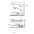
- FIG. 1 is a configuration diagram schematically showing a configuration of a communication system including a communication connector in Embodiment 1.
- FIG. It is a block diagram which shows the internal structure of the communication connector which comprises the vehicle-mounted communication system in Embodiment 1, and ECU. 6 is a block diagram showing a configuration of an in-vehicle communication system in a second embodiment.
- FIG. FIG. 10 is a block diagram showing a configuration of an in-vehicle communication system in a third embodiment.
- FIG. 10 is a block diagram showing a configuration of an in-vehicle communication system in a fourth embodiment.
- FIG. 10 is a block diagram showing a configuration of an in-vehicle communication system extended using a communication connector in a fourth embodiment.
- 1 is a schematic perspective view schematically showing the appearance of a communication connector.
- FIG. 1 is a configuration diagram schematically showing the configuration of the in-vehicle communication system 102 including the communication connector in the first embodiment, and FIG. It is a block diagram which shows an internal structure.
- reference numeral 1 denotes a communication connector, which has a connecting portion 10 made of a plug, and is connected so as to be fitted to a receptacle provided with an input / output portion 20 of an ECU shown in FIG.
- a plurality of communication connectors 1 are connected to a communication line 100 shown in the figure, and constitute a communication harness 101.
- An in-vehicle communication system 102 is configured.
- the communication connector 1 has a substantially rectangular parallelepiped shape as shown in FIG. 1, and the communication line 100 connected to the inside is exposed from one surface, and is connected to the ECU 2 from the surface facing the one surface. It has a plug-shaped connecting portion 10.
- the communication connector 1 includes a network controller 11 and a transceiver 12 in addition to the connection unit 10.
- connection unit 10 is constituted by a plug formed so as to be connected to an input / output unit 20 of the ECU 2 described later, and a signal line from the network controller 11 is provided therein.
- the network controller 11 performs communication control by interpreting, for example, a MOST (registered trademark, Media Oriented Systems Transport) protocol. That is, the network controller 11 controls the data link layer in the MOST protocol. Specifically, the network controller 11 interprets a message for instructing data transmission from a microcomputer 200 (hereinafter referred to as “microcomputer” and referred to as ⁇ C in the figure) of the ECU 2 to be described later and interprets a digital data signal based on the MOST protocol. And are provided for transmission to the transceiver 12. The network controller 11 interprets the digital signal input from the transceiver 12 based on the MOST protocol, extracts data or a message, and passes the data or message to the microcomputer 200.
- MOST registered trademark, Media Oriented Systems Transport
- the network controller 11 may use a network controller chip or may be configured with an ASIC.
- the network controller 11 may be configured as software using a processor that executes a program.
- the communication protocol conforming to the network controller 11 is not limited to MOST.
- Other protocols such as IEEE1394, CAN (Controller Area Network), FlexRay (registered trademark), and LIN (Local Interconnect Network) may be used.
- the communication line 100 may be a MOST POF (Pipe Type Filled) cable, a CAN TP (Twisted Pair) cable, or an IEEE 1394 cable.
- the network controller 11 has a protocol conversion function between the specific protocol and the communication protocol via the communication line 100 when transmission / reception of a signal to / from the input / output unit 20 of the ECU 2 is a specific protocol. May be. It may have a protocol conversion function or a buffering processing function for absorbing a communication speed difference.
- the transceiver 12 generates a signal conforming to the MOST protocol based on the digital signal given from the network controller 11 and sends it to the communication line 100.
- the transceiver 12 detects a signal from the communication line 100 and passes it to the network controller 11 as a digital signal. That is, the transceiver 12 is responsible for the physical layer in the MOST protocol.
- the transceiver 12 according to the CAN protocol transmits a differential signal to the communication line 100 based on the CAN signal given from the network controller 11, detects a potential difference in the communication line 100, and transmits it to the network controller 11 as a digital signal. hand over.
- the ECU 2 includes a microcomputer 200 having an input / output unit 20, a control unit 21, and a memory 22.
- the ECU 2 controls various in-vehicle devices such as sensors or actuators (not shown) arranged in the vehicle.
- the ECU 2 may have other components in addition to the microcomputer 200.
- the input / output unit 20 is a general-purpose interface for the microcomputer 200, and exchanges signals between the control unit 21 described later and other components or external devices.
- the input / output unit 20 has a bus shape and is provided in the receptacle.
- the control unit 21 uses a CPU (Central Processing Unit) or an MPU (Micro Processing Unit) to execute control processing of the in-vehicle device based on a program (not shown) stored in the memory 22.
- the control unit 21 is connected to the input / output unit 20 by an internal bus.
- the control unit 21 exchanges messages (digital signals) with other components or external devices such as the communication connector 1 via the input / output unit 20.
- the memory 22 uses flash memory, EEPROM (Electrically-Erasable-and Programmable-Read-Only-Memory), or DRAM (Dynamic-Random-Access Memory).
- the program includes a flash memory in which a program and control information referred to by the control unit 21 are stored, and a DRAM that temporarily stores information generated by the processing of the control unit 21.
- the ECU 2 transmits and receives data with other ECUs 2 through the communication line 100, and operates in cooperation such as performing control using information acquired or calculated by the other ECUs 2 to realize various functions.
- the communication connector 1 includes the network controller 11 and the transceiver 12 as described above
- the control unit 20 of the ECU 2 can provide any message and data for transmitting data to the communication connector 1, and what is the communication protocol. Regardless of this, data can be transmitted.
- the ECUs 2, 2,... Do not depend on the protocol, and the microcomputer 200 may have a minimum configuration using only the general-purpose interface, and the cost can be reduced.
- ECU microcomputers included in in-vehicle communication systems are preferably configured to be compatible with various communication protocols and switchable, and such microcomputers are often expensive.
- the communication connector 1 according to the first embodiment it is possible to use a microcomputer having a minimum function because it does not depend on the communication protocol.
- the communication line 100 including the communication connector 1, that is, the communication harness 101 can be connected to the ECUs 2, 2 as necessary, it is possible to easily construct the in-vehicle communication system 102 having various connection configurations. It becomes possible.
- the communication harness 101 in which three or more communication connectors 1, 1, 1 are connected to the communication line 100 by bus is shown.
- the present invention is not limited to this, and the communication harness 101 including the two communication connectors to which the communication connector 1 is connected only to both ends of the communication line 100 and the single communication line 100 may be used.
- the communication harness 101 including the two communication connectors to which the communication connector 1 is connected only to both ends of the communication line 100 and the single communication line 100 may be used.
- P2P connection between two ECUs 2 and 2 can be applied.
- P2P communication between the ECUs 2 and 2 that performs transmission / reception of information systems, that is, video signals and audio signals can be realized.
- the ECU 2 can realize data transmission / reception regardless of whether the communication protocol with the counterpart ECU 2 that performs P2P communication is IEEE 1394 or MOST.
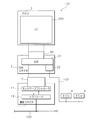
- FIG. 3 is a block diagram illustrating a configuration of the in-vehicle communication system 104 according to the second embodiment. Note that, in the configuration of the in-vehicle communication system 104 in the second embodiment, the same reference numerals are given to the same configurations as those in the first embodiment, and detailed description thereof is omitted.
- FIG. 3 is a GW (Gateway) connector having a relay function.
- a communication line 103 different from the communication line 100 is connected to the GW connector 3.
- the communication line 103 is connected to ECUs 4, 4,.
- the GW connector 3 is connected so as to be sandwiched between the communication connector 1 and the ECU 2.
- the GW connector 3 includes an ECU 2 that is directly connected to itself, and is connected to the ECUs 2, 2,... Connected to the communication line 100 connected via the communication connector 1, and the communication line 103 connected to itself. Relays data transmission and reception between the ECUs 4, 4,.
- the GW connector 3 has a flat and substantially rectangular parallelepiped shape, and includes a plug-like connection portion 30 corresponding to the receptacle of the input / output unit 20 of the ECU 2 on one surface.
- the GW connector 3 includes a GW 31 and a connection unit 32 in addition to the connection unit 30.
- connection unit 30 is composed of a plug formed so as to be connected to the input / output unit 20 of the ECU 2, and a signal line from the GW 31 is provided therein.
- the connection unit 32 is connected to the communication line 103 and has the functions of the network controller 11 and the transceiver 12, detects a signal transmitted to the communication line 103, and interprets the signal based on the communication protocol in the communication line 103. The data or message is taken out and passed to the GW 31.
- the GW 31 is a circuit that performs a relay process, and has a receptacle to which the connection portion 10 of the communication connector 1 can be fitted.
- the GW 31 receives a digital signal corresponding to data or a message passed from the communication connector 1 and a digital signal corresponding to data or a message passed from the communication line 103 via the connection unit 32.
- the GW 31 determines whether it is necessary to relay between the communication lines 100 and 103 that are different from each other, based on information that identifies the content of the signal.
- the GW 31 gives the digital signal to the communication connector 1 (or the connection unit 32) so as to transmit the digital signal to a different communication line 100 (or 103).
- the GW 31 has a ROM (Read Only Memory) therein, stores signal identification information for determining whether relaying is necessary, and a table indicating the necessity and correspondence, and determines whether relaying is necessary.
- connection unit 32 has the functions of the network controller 11 and the transceiver 12, and the data or message input / output from the connection unit 10 in the communication connector 1 is information after being interpreted based on the MOST protocol. Therefore, the GW 31 is general-purpose because it can perform relay processing regardless of the protocol in the communication line 100 and the communication line 103. However, the GW 31 may have a function of the network controller 11 that interprets the protocol of the communication line 103, and the connection unit 32 may be configured to exhibit only the function of the transceiver 12.
- connection unit 32 is configured to be detachable according to the protocol of the communication line 103, that is, the communication connector 1 connected to the communication line 103 is connected to the GW 31 instead of the connection unit 32. It may be realized.
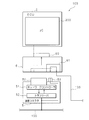
- FIG. 4 is a block diagram showing the configuration of the in-vehicle communication system 105 in the third embodiment.
- the same reference numerals are given to configurations common to the first or second embodiment, and detailed description thereof is omitted.
- the communication connector 5 has the same shape as that of the communication connector 1 according to the first embodiment, includes a connection unit 50, and includes a network controller 51 and a transceiver 52 therein. Since the functions of the network controller 51 and the transceiver 52 are the same as those in the communication connector 1 of the first embodiment, detailed description thereof is omitted.
- the communication connector 5 includes a signal line branched from the communication line 100 and includes an output terminal 53 that branches and outputs a communication signal transmitted to the communication line 100.
- the output terminal 53 is a plug provided in parallel with the connection unit 50.
- the connecting portion 50 and the output terminal 53 can be fitted together in a later-described bus bar 6 or a receptacle of the input / output portion 20 of the ECU 2.
- the bus bar 6 is configured to be connected so as to be sandwiched between the communication connector 5 and the ECU 2.
- the bus bar 6 connects between the connection portion 50 of the communication connector 5 and the input / output portion 20 of the ECU 2, and connects the output terminal 53 of the communication connector 5 and the communication line 103.
- a signal line or a communication line is mounted on the substrate so as to be connected.
- the connection unit 50 and the input / output unit 20 may be connected to each other, and the terminal group may be configured to connect the output terminal 53 and the communication line 103.
- the communication signal transmitted to the communication line 100 can be branched, and the communication line 100 and the communication line 103 can be expanded as one network. Accordingly, the system can be expanded by an easy operation even if the communication harness is not provided with an expansion connector that is unknown whether it is used.
- the communication connector 5 in the third embodiment is connected to the ECU 2 via the bus bar 6.
- the present invention is not limited to this, and the communication connector 5 may be directly connected to the ECU 2.
- the function of the microcomputer 200 of the ECU 2 can detect whether or not a failure has occurred in the communication connector 5 by detecting the signal in the communication line 100 without solving the protocol. is there.
- the microcomputer 200 has an abnormality in the communication connector 5 when a digital signal of data or a message received from the communication connector 5 is not passed even though a signal is detected on the communication line 100. Or the like.
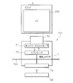
- FIG. 5 is a block diagram illustrating a configuration of the in-vehicle communication system according to the fourth embodiment.
- the same reference numerals are given to configurations common to the first or second embodiment, and detailed description thereof is omitted.
- the communication connector 7 has the same shape as that of the communication connector 1 according to the first embodiment, includes a connection unit 70, and includes a network controller 71 and a transceiver 72 to which a communication line 700 is connected. Since the functions of the network controller 71 and the transceiver 72 are the same as those in the communication connector 1 of the first embodiment, detailed description thereof is omitted.
- the communication connector 7 further includes a connection portion 73 on a surface opposite to the surface on which the connection portion 70 is provided. Similar to the output terminal 53 in the third embodiment, the connection unit 73 is configured to branch the communication signal transmitted to the communication line 700, and is provided in the receptacle. It is also possible to expand the network by connecting another communication connector 7 to the connection unit 73.
- the extension circuit 80 is, for example, a termination circuit, has a plug corresponding to the connection portion 73 of the communication connector 7, and is connected so as to be fitted to the connection portion 73 of the communication connector 7.
- the extension circuit 80 may be a filter circuit that removes noise in the communication line 700 in addition to the termination circuit.
- the bus connection is formed by the communication harness 701 including the communication connector 7 having the connection portion 73 for connecting the extension circuit 80 and the communication line 700, and the electrical signal characteristics are desired depending on the length and the branching state of the harness.
- an extension circuit 80 which is an electric circuit for improving signal characteristics such as a termination circuit and a filter circuit, is connected to the connection portion 73 and disposed at any appropriate location.
- a configuration in which a plurality of communication connectors 7 are connected to the communication line 700 on the communication harness 701 may be employed.
- the communication harness 701 it is possible to expand various physical connections in the bus connection, and by connecting the expansion circuit 80, electrical signal characteristics in communication satisfy desired characteristics.
- an expansion circuit 80 may be installed at a necessary place or an optimum place at a necessary minimum corresponding to the form of a communication harness that changes with the addition of an on-vehicle option device.
- the electrical signal characteristics of the communication harness can be effectively improved.
- the communication harness 701 including the communication line 700 to which the communication connector 7 according to the fourth embodiment is connected, the communication harness 701 can be easily expanded by simply connecting the ECUs 2, 2,.
- a vehicle-mounted communication system can be constructed.
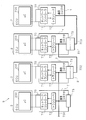
- FIG. 6 is a block diagram showing a configuration of the in-vehicle communication system 9 extended using the communication connector 7 in the fourth embodiment
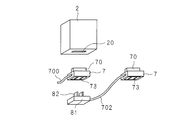
- FIG. 7 shows a partial appearance of the in-vehicle communication system in the fourth embodiment. It is a schematic perspective view showing typically.
- the in-vehicle communication system 9 shown in FIGS. 6 and 7 includes two communication connectors 7 and 7 connected to the communication line 700 and an ECU 2 connected to each of the two communication connectors 7 and 7. It is assumed that the communication line 700, the two communication connectors 7 and 7, and the ECUs 2 and 2 are systems corresponding to standard equipment.
- a communication connector 7 is further connected to the communication connector 7 connected to the end of the communication line 700. It is realized by doing.
- the communication connector 7 to be further connected at this time is connected to the communication line 702 through the internal transceiver 72 and the connection unit 73, and an expansion connector 81 having an expansion plug 82 is connected to the communication line 702. .
- the expansion of the system is realized by connecting the plug 82 of the expansion connector 81 to the connection portion 73 of the end communication connector 7 in the system corresponding to the standard equipment.
- the extension connector 81 sends a communication signal of the communication line 700 branched and output from the connection unit 73 connected via the plug 82 to the communication line 702. At this time, the extension connector 81 can be connected to the communication connector 7 as long as the plug 82 is inserted into the communication connector 7 as shown in FIG.
- the communication connector 7 connected via the communication line 702 is connected to the system. Further, it is realized by connecting the communication connector 1.
- the communication connector 1 in a form that does not have the expansion connection portion shown in the first embodiment may be used.
- the communication connector 1 is connected to the communication connector 7 to which the communication line 702 is connected.
- the communication connector 1 constituting the in-vehicle communication system 9 is connected to an expansion connector 81 having an expansion plug 82 via a communication line 703.
- the plug 82 of the expansion connector 81 By connecting the plug 82 of the expansion connector 81 to the connection portion 73 of the communication connector 7 to which the communication line 702 is connected, further expansion of the system is realized, and the in-vehicle communication system 9 shown in FIG. 6 is constructed. .
- the extension connector 81 connected to the communication connector 1 further branches the communication signal of the communication line 702 branched and output from the connection unit 73 connected via the plug 82 and sends it to the communication line 703.
- the communication connector 1 (or 5, 7) realizes processing based on the communication protocol. Therefore, the ECU 2 is a system that employs any communication protocol. A common configuration can be used without depending on the protocol. The ECU 2 can be realized with an inexpensive configuration because it is not necessary to prepare a microcomputer corresponding to a network controller conforming to various communication protocols.
- connection portion 10 (or 50, 70, 73) in the communication connector 1 (or 5, 7) is fitted to the signal line provided inside to contact the signal input.
- the configuration is not limited to output. Even though the connection unit 10 and the input / output unit 20 are configured to physically fit, the signal lines provided therein are configured to be input / output (communication) by contactless wireless transfer without contact. Also good.
Landscapes
- Engineering & Computer Science (AREA)
- Computer Networks & Wireless Communication (AREA)
- Signal Processing (AREA)
- Computer Security & Cryptography (AREA)
- Mechanical Engineering (AREA)
- Small-Scale Networks (AREA)
- Communication Control (AREA)
Abstract
Description
なお、以下に示す実施の形態では、本発明に係る通信コネクタを車載通信システムに用いる場合を例に挙げて説明する。
図1は、実施の形態1における通信コネクタを含む車載通信システム102の構成を模式的に示す構成図であり、図2は、実施の形態1における車載通信システム102を構成する通信コネクタ及びECUの内部構成を示すブロック図である。図中1が通信コネクタであり、プラグからなる接続部10を有し、2に示すECUの入出力部20が設けられたレセプタクルと嵌合するように接続される。通信コネクタ1は、図中100に示す通信線に複数接続されており、通信ハーネス101を構成する。
実施の形態2では、通信システムを拡張するGWの機能を内蔵したコネクタを更に備える車載通信システムの例を説明する。図3は、実施の形態2における車載通信システム104の構成を示すブロック図である。なお、実施の形態2における車載通信システム104の構成の内、実施の形態1と共通する構成については同一の符号を付して詳細な説明を省略する。
実施の形態2では、通信コネクタ1はGWコネクタ3を挟むようにしてECU2に接続される構成とした。このとき中継機能は必須ではなく、通信線100の通信信号を分岐させるバスバーのみでもよい。図4は、実施の形態3における車載通信システム105の構成を示すブロック図である。実施の形態3における車載通信システム105の構成の内、実施の形態1又は2と共通する構成については同一の符号を付して詳細な説明を省略する。
図5は、実施の形態4における車載通信システムの構成を示すブロック図である。実施の形態3における車載通信システム105の構成の内、実施の形態1又は2と共通する構成については同一の符号を付して詳細な説明を省略する。
10,50,70 接続部
11,51,71 ネットワークコントローラ
12,52,72 トランシーバ
73 接続部(出力端子)
53 出力端子
100,700 通信線
101 通信ハーネス
102,104,105,9 車載通信システム
103,702,703 通信線
2 ECU
3 GWコネクタ(中継通信コネクタ)
30 接続部
31 GW
Claims (10)
- 外部装置との接続部を有し、該外部装置から他へ送信すべきデータの指示を受け付け、他から受信した信号が示すデータを前記外部装置へ渡す第1通信部と、
通信線に接続され、第1通信部を介して前記外部装置から受信したデータに基づく所定のプロトコルに応じた通信信号を前記通信線へ出力し、通信線に出力されている通信信号を検知して第1通信部へ出力する第2通信部と
を備えることを特徴とする通信コネクタ。 - 第1通信部は、
前記接続部を介して受け付けた指示されたデータを含み、前記所定のプロトコルに基づく通信信号を作成する手段と、
作成した通信信号を第2通信部へ与える手段と、
第2通信部から与えられた通信信号を、前記所定のプロトコルに基づき解釈してデータを取得する手段と
を備えることを特徴とする請求項1に記載の通信コネクタ。 - 第2通信部が検知した通信信号を外部へ出力する出力端子を更に備えること
を特徴とする請求項1又は2に記載の通信コネクタ。 - 略直方体形状をなす筐体を有し、
該筐体の一の面に前記接続部を、前記一の面の反対面に前記出力端子を備えること
を特徴とする請求項3に記載の通信コネクタ。 - プラグ及びレセプタクルを有し、前記接続部はプラグであり、前記出力端子はレセプタクルに設けられていること
を特徴とする請求項4に記載の通信コネクタ。 - 第1通信部は、外部装置との間の通信と、前記所定のプロトコルに基づく通信との間のプロトコル変換機能を有すること
を特徴とする請求項1乃至5のいずれかに記載の通信コネクタ。 - 請求項1乃至6のいずれかに記載の一又は複数の通信コネクタと、該一又は複数の通信コネクタが第2通信部にて接続されている通信線と
を含むことを特徴とする通信ハーネス。 - 請求項1乃至6のいずれかに記載の通信コネクタと、該通信コネクタが第2通信部にて接続されている通信線と、データを送受信する複数の通信装置とを含む通信システムであって、
前記通信装置の少なくとも1つは、送信するデータの指示を出力し、受信信号の通知を受け付けるようにしてあり、前記通信コネクタの第1通信部に接続されていること
を特徴とする通信システム。 - 請求項1乃至6のいずれかに記載の通信コネクタと、該通信コネクタが第2通信部にて接続されている通信線と、データを送受信する複数の通信装置とを含む通信システムであって、
前記通信装置の少なくとも1つは、送信するデータの指示を出力し、受信信号の通知を受け付けるようにしてあり、
前記通信線と異なる通信線に接続され、前記1つの通信装置と接続する第1接続部と、前記通信コネクタの第1通信部と接続する第2接続部とを有し、2つの通信線間での通信信号の中継要否の判断処理及び中継先の特定処理を行なう中継処理回路を内蔵する中継通信コネクタを更に含むこと
を特徴とする通信システム。 - 前記中継通信コネクタの第1接続部は、前記通信装置に備えられるレセプタクルに対応するプラグを有し、
第2接続部は、前記通信コネクタの第1通信部が有するプラグに対応するレセプタクルを備えること
を特徴とする請求項9に記載の通信システム。
Priority Applications (5)
| Application Number | Priority Date | Filing Date | Title |
|---|---|---|---|
| US13/580,085 US8935454B2 (en) | 2010-02-26 | 2011-02-25 | Connectors transmitting/receiving an input/output signal as a communication signal, communication harness with the connectors, and the communication system with the connectors |
| KR1020127024898A KR101430854B1 (ko) | 2010-02-26 | 2011-02-25 | 통신 커넥터, 통신 하네스 및 통신 시스템 |
| CN201180011301.9A CN102783093B (zh) | 2010-02-26 | 2011-02-25 | 通信连接器、通信线束及通信系统 |
| JP2012501879A JP5445667B2 (ja) | 2010-02-26 | 2011-02-25 | 通信コネクタ、通信ハーネス及び通信システム |
| DE112011100694T DE112011100694T5 (de) | 2010-02-26 | 2011-02-25 | Kommunikationsverbinder, Kommunikationskabelbaum und Kommunikatiossystem |
Applications Claiming Priority (2)
| Application Number | Priority Date | Filing Date | Title |
|---|---|---|---|
| JP2010-043126 | 2010-02-26 | ||
| JP2010043126 | 2010-02-26 |
Publications (1)
| Publication Number | Publication Date |
|---|---|
| WO2011105545A1 true WO2011105545A1 (ja) | 2011-09-01 |
Family
ID=44506942
Family Applications (1)
| Application Number | Title | Priority Date | Filing Date |
|---|---|---|---|
| PCT/JP2011/054264 Ceased WO2011105545A1 (ja) | 2010-02-26 | 2011-02-25 | 通信コネクタ、通信ハーネス及び通信システム |
Country Status (6)
| Country | Link |
|---|---|
| US (1) | US8935454B2 (ja) |
| JP (1) | JP5445667B2 (ja) |
| KR (1) | KR101430854B1 (ja) |
| CN (1) | CN102783093B (ja) |
| DE (1) | DE112011100694T5 (ja) |
| WO (1) | WO2011105545A1 (ja) |
Cited By (6)
| Publication number | Priority date | Publication date | Assignee | Title |
|---|---|---|---|---|
| JP2017034340A (ja) * | 2015-07-29 | 2017-02-09 | 日立建機株式会社 | 電子制御装置 |
| JP2019006394A (ja) * | 2018-09-21 | 2019-01-17 | 矢崎総業株式会社 | 車両用ハーネス構造 |
| WO2020122145A1 (ja) * | 2018-12-11 | 2020-06-18 | 株式会社オートネットワーク技術研究所 | ワイヤハーネス、コネクタ及び通信中継方法 |
| WO2020122140A1 (ja) * | 2018-12-11 | 2020-06-18 | 株式会社オートネットワーク技術研究所 | ワイヤハーネス及び通信中継方法 |
| WO2020121388A1 (ja) * | 2018-12-11 | 2020-06-18 | 株式会社オートネットワーク技術研究所 | コネクタ、車載装置及び通信中継方法 |
| US10741979B2 (en) | 2014-05-30 | 2020-08-11 | Yazaki Corporation | Vehicle harness structure and additional connection member |
Families Citing this family (14)
| Publication number | Priority date | Publication date | Assignee | Title |
|---|---|---|---|---|
| JP5907499B2 (ja) * | 2011-05-11 | 2016-04-26 | 矢崎総業株式会社 | 中継装置およびコネクタ |
| DE102011080169A1 (de) * | 2011-08-01 | 2013-02-07 | Robert Bosch Gmbh | Kommunikationsanbindung für Sensorik in Fahrzeug-Regelsystemen |
| JP6380795B2 (ja) * | 2014-10-15 | 2018-08-29 | 日本精機株式会社 | 車両用表示装置 |
| CN105975423B (zh) * | 2016-04-01 | 2018-10-26 | 上海傲意信息科技有限公司 | 点对点信号级联传输装置及方法、便携电子设备 |
| US10647369B2 (en) | 2016-10-07 | 2020-05-12 | Phillips Connect Technologies Llc | Modular harness system |
| MX2019004047A (es) | 2016-10-07 | 2019-10-15 | Phillips Connect Tech Llc | Sistema de tráiler inteligente. |
| JP7094670B2 (ja) * | 2017-07-03 | 2022-07-04 | 矢崎総業株式会社 | 設定装置及びコンピュータ |
| JP6965767B2 (ja) * | 2018-01-23 | 2021-11-10 | 株式会社デンソー | 車載通信システム |
| WO2019199990A1 (en) * | 2018-04-11 | 2019-10-17 | Phillips Connect Technologies Llc | Modular harness system |
| JP7070260B2 (ja) * | 2018-09-10 | 2022-05-18 | 株式会社オートネットワーク技術研究所 | 配線分岐箱 |
| WO2020121390A1 (ja) * | 2018-12-11 | 2020-06-18 | 株式会社オートネットワーク技術研究所 | ジョイントコネクタ |
| CN111224748A (zh) * | 2019-12-26 | 2020-06-02 | 北京启冠智能科技股份有限公司 | 有线网络传输数据 |
| JP2022148528A (ja) * | 2021-03-24 | 2022-10-06 | 株式会社オートネットワーク技術研究所 | 車載通信装置及び車載通信システム |
| DE102023203292A1 (de) * | 2023-04-12 | 2024-10-17 | Zf Friedrichshafen Ag | Kraftfahrzeug |
Citations (3)
| Publication number | Priority date | Publication date | Assignee | Title |
|---|---|---|---|---|
| JPH1032883A (ja) * | 1996-07-16 | 1998-02-03 | Alps Electric Co Ltd | 車両用多重通信装置 |
| JP2005348064A (ja) * | 2004-06-02 | 2005-12-15 | Denso Corp | 通信システム、暗号化/復号中継装置、及び通信制御装置 |
| JP2007203764A (ja) * | 2006-01-31 | 2007-08-16 | Nippon Seiki Co Ltd | 車両用表示装置 |
Family Cites Families (6)
| Publication number | Priority date | Publication date | Assignee | Title |
|---|---|---|---|---|
| JPH0428439A (ja) | 1990-05-22 | 1992-01-31 | Matsushita Electric Ind Co Ltd | 軸受プレートの製造方法 |
| JP3817855B2 (ja) | 1997-08-29 | 2006-09-06 | 株式会社デンソー | 電子制御装置 |
| JP4028439B2 (ja) | 2003-06-13 | 2007-12-26 | 古河電気工業株式会社 | 回路基板内蔵型コネクタ |
| CN1735090A (zh) * | 2004-03-18 | 2006-02-15 | 上海电器科学研究所(集团)有限公司 | 现场总线设备通讯的通信适配器 |
| JP5107608B2 (ja) | 2007-05-16 | 2012-12-26 | 矢崎総業株式会社 | 中継コネクタユニット及び電子機器通信システム |
| DE102012215765A1 (de) * | 2012-09-05 | 2014-05-15 | Robert Bosch Gmbh | Gateway-Modul für ein Kommunikationssystem, Kommunikationssystem und Verfahren zur Übertragung von Daten zwischen Teilnehmern eines Kommunikationssystems |
-
2011
- 2011-02-25 JP JP2012501879A patent/JP5445667B2/ja not_active Expired - Fee Related
- 2011-02-25 WO PCT/JP2011/054264 patent/WO2011105545A1/ja not_active Ceased
- 2011-02-25 CN CN201180011301.9A patent/CN102783093B/zh not_active Expired - Fee Related
- 2011-02-25 DE DE112011100694T patent/DE112011100694T5/de not_active Withdrawn
- 2011-02-25 US US13/580,085 patent/US8935454B2/en not_active Expired - Fee Related
- 2011-02-25 KR KR1020127024898A patent/KR101430854B1/ko not_active Expired - Fee Related
Patent Citations (3)
| Publication number | Priority date | Publication date | Assignee | Title |
|---|---|---|---|---|
| JPH1032883A (ja) * | 1996-07-16 | 1998-02-03 | Alps Electric Co Ltd | 車両用多重通信装置 |
| JP2005348064A (ja) * | 2004-06-02 | 2005-12-15 | Denso Corp | 通信システム、暗号化/復号中継装置、及び通信制御装置 |
| JP2007203764A (ja) * | 2006-01-31 | 2007-08-16 | Nippon Seiki Co Ltd | 車両用表示装置 |
Cited By (12)
| Publication number | Priority date | Publication date | Assignee | Title |
|---|---|---|---|---|
| US10741979B2 (en) | 2014-05-30 | 2020-08-11 | Yazaki Corporation | Vehicle harness structure and additional connection member |
| JP2017034340A (ja) * | 2015-07-29 | 2017-02-09 | 日立建機株式会社 | 電子制御装置 |
| JP2019006394A (ja) * | 2018-09-21 | 2019-01-17 | 矢崎総業株式会社 | 車両用ハーネス構造 |
| WO2020122145A1 (ja) * | 2018-12-11 | 2020-06-18 | 株式会社オートネットワーク技術研究所 | ワイヤハーネス、コネクタ及び通信中継方法 |
| WO2020122140A1 (ja) * | 2018-12-11 | 2020-06-18 | 株式会社オートネットワーク技術研究所 | ワイヤハーネス及び通信中継方法 |
| WO2020121388A1 (ja) * | 2018-12-11 | 2020-06-18 | 株式会社オートネットワーク技術研究所 | コネクタ、車載装置及び通信中継方法 |
| WO2020122144A1 (ja) * | 2018-12-11 | 2020-06-18 | 株式会社オートネットワーク技術研究所 | コネクタ、車載装置及び通信中継方法 |
| JPWO2020122145A1 (ja) * | 2018-12-11 | 2021-02-15 | 株式会社オートネットワーク技術研究所 | ワイヤハーネス、コネクタ及び通信中継方法 |
| JPWO2020122140A1 (ja) * | 2018-12-11 | 2021-02-15 | 株式会社オートネットワーク技術研究所 | ワイヤハーネス及び通信中継方法 |
| US20220045876A1 (en) * | 2018-12-11 | 2022-02-10 | Autonetworks Technologies, Ltd. | Wire harness and communication relay method |
| US11472353B2 (en) | 2018-12-11 | 2022-10-18 | Autonetworks Technologies, Ltd. | Wire harness, connector, and communication relay method |
| US11936495B2 (en) | 2018-12-11 | 2024-03-19 | Autonetworks Technologies, Ltd. | Wire harness and communication relay method |
Also Published As
| Publication number | Publication date |
|---|---|
| CN102783093B (zh) | 2016-12-21 |
| JP5445667B2 (ja) | 2014-03-19 |
| KR101430854B1 (ko) | 2014-09-22 |
| US20120327978A1 (en) | 2012-12-27 |
| JPWO2011105545A1 (ja) | 2013-06-20 |
| KR20130004913A (ko) | 2013-01-14 |
| CN102783093A (zh) | 2012-11-14 |
| US8935454B2 (en) | 2015-01-13 |
| DE112011100694T5 (de) | 2013-03-07 |
Similar Documents
| Publication | Publication Date | Title |
|---|---|---|
| JP5445667B2 (ja) | 通信コネクタ、通信ハーネス及び通信システム | |
| CN105579318B (zh) | 控制设备在诊断总线和外部的以太网连接之间的模式转换 | |
| CN102666206B (zh) | 一种通信系统 | |
| JP5022740B2 (ja) | 中継コネクタユニット、ワイヤハーネス組付体、及び、電子機器制御システム | |
| JP6927412B2 (ja) | ワイヤハーネス、コネクタ及び通信中継方法 | |
| EP2346214B1 (en) | Communication circuit, relay connecting circuit, and communication network | |
| US11801798B2 (en) | Joint connector | |
| JP5107608B2 (ja) | 中継コネクタユニット及び電子機器通信システム | |
| JP2012235427A (ja) | バスコントローラの接続方法および通信システム | |
| JP6593550B2 (ja) | 車載通信システム | |
| JP2004142500A (ja) | コネクタ装置 | |
| JPWO2020122140A1 (ja) | ワイヤハーネス及び通信中継方法 | |
| JP5192353B2 (ja) | 通信回路、通信装置、通信システム及び通信機器集約装置 | |
| JP2007336267A (ja) | 車載通信システム | |
| JP2010105632A (ja) | 通信機器集約装置 | |
| JP2011135521A (ja) | 光通信装置、通信ハーネス及び通信システム | |
| JP5359449B2 (ja) | 中継システム及び制御装置 | |
| US7575437B2 (en) | Wiring harness with integrated two-way in-line connection capability | |
| WO2020121388A1 (ja) | コネクタ、車載装置及び通信中継方法 | |
| JP5763368B2 (ja) | 中継コネクタ、ワイヤハーネス構造体、及び、識別情報設定治具 | |
| KR101126640B1 (ko) | 무선 네트워크를 이용한 most 네트워크 진단 시스템 및 방법 | |
| JP5312178B2 (ja) | 車載通信装置 | |
| CN117555260A (zh) | 客车大数据总线控制系统 | |
| WO2020121387A1 (ja) | 車載装置及び通信線接続体 | |
| KR20070072697A (ko) | 통신라인의 결선방법 |
Legal Events
| Date | Code | Title | Description |
|---|---|---|---|
| WWE | Wipo information: entry into national phase |
Ref document number: 201180011301.9 Country of ref document: CN |
|
| 121 | Ep: the epo has been informed by wipo that ep was designated in this application |
Ref document number: 11747501 Country of ref document: EP Kind code of ref document: A1 |
|
| WWE | Wipo information: entry into national phase |
Ref document number: 13580085 Country of ref document: US |
|
| WWE | Wipo information: entry into national phase |
Ref document number: 2012501879 Country of ref document: JP |
|
| WWE | Wipo information: entry into national phase |
Ref document number: 1120111006942 Country of ref document: DE Ref document number: 112011100694 Country of ref document: DE |
|
| ENP | Entry into the national phase |
Ref document number: 20127024898 Country of ref document: KR Kind code of ref document: A |
|
| 122 | Ep: pct application non-entry in european phase |
Ref document number: 11747501 Country of ref document: EP Kind code of ref document: A1 |