WO2011105127A1 - 車両用駆動装置 - Google Patents
車両用駆動装置 Download PDFInfo
- Publication number
- WO2011105127A1 WO2011105127A1 PCT/JP2011/050455 JP2011050455W WO2011105127A1 WO 2011105127 A1 WO2011105127 A1 WO 2011105127A1 JP 2011050455 W JP2011050455 W JP 2011050455W WO 2011105127 A1 WO2011105127 A1 WO 2011105127A1
- Authority
- WO
- WIPO (PCT)
- Prior art keywords
- transmission
- state
- driving force
- rotation
- control unit
- Prior art date
- Legal status (The legal status is an assumption and is not a legal conclusion. Google has not performed a legal analysis and makes no representation as to the accuracy of the status listed.)
- Ceased
Links
Images




Classifications
-
- B—PERFORMING OPERATIONS; TRANSPORTING
- B60—VEHICLES IN GENERAL
- B60W—CONJOINT CONTROL OF VEHICLE SUB-UNITS OF DIFFERENT TYPE OR DIFFERENT FUNCTION; CONTROL SYSTEMS SPECIALLY ADAPTED FOR HYBRID VEHICLES; ROAD VEHICLE DRIVE CONTROL SYSTEMS FOR PURPOSES NOT RELATED TO THE CONTROL OF A PARTICULAR SUB-UNIT
- B60W10/00—Conjoint control of vehicle sub-units of different type or different function
- B60W10/02—Conjoint control of vehicle sub-units of different type or different function including control of driveline clutches
-
- B—PERFORMING OPERATIONS; TRANSPORTING
- B60—VEHICLES IN GENERAL
- B60W—CONJOINT CONTROL OF VEHICLE SUB-UNITS OF DIFFERENT TYPE OR DIFFERENT FUNCTION; CONTROL SYSTEMS SPECIALLY ADAPTED FOR HYBRID VEHICLES; ROAD VEHICLE DRIVE CONTROL SYSTEMS FOR PURPOSES NOT RELATED TO THE CONTROL OF A PARTICULAR SUB-UNIT
- B60W10/00—Conjoint control of vehicle sub-units of different type or different function
- B60W10/02—Conjoint control of vehicle sub-units of different type or different function including control of driveline clutches
- B60W10/024—Conjoint control of vehicle sub-units of different type or different function including control of driveline clutches including control of torque converters
- B60W10/026—Conjoint control of vehicle sub-units of different type or different function including control of driveline clutches including control of torque converters of lock-up clutches
-
- B—PERFORMING OPERATIONS; TRANSPORTING
- B60—VEHICLES IN GENERAL
- B60W—CONJOINT CONTROL OF VEHICLE SUB-UNITS OF DIFFERENT TYPE OR DIFFERENT FUNCTION; CONTROL SYSTEMS SPECIALLY ADAPTED FOR HYBRID VEHICLES; ROAD VEHICLE DRIVE CONTROL SYSTEMS FOR PURPOSES NOT RELATED TO THE CONTROL OF A PARTICULAR SUB-UNIT
- B60W10/00—Conjoint control of vehicle sub-units of different type or different function
- B60W10/04—Conjoint control of vehicle sub-units of different type or different function including control of propulsion units
- B60W10/06—Conjoint control of vehicle sub-units of different type or different function including control of propulsion units including control of combustion engines
-
- B—PERFORMING OPERATIONS; TRANSPORTING
- B60—VEHICLES IN GENERAL
- B60W—CONJOINT CONTROL OF VEHICLE SUB-UNITS OF DIFFERENT TYPE OR DIFFERENT FUNCTION; CONTROL SYSTEMS SPECIALLY ADAPTED FOR HYBRID VEHICLES; ROAD VEHICLE DRIVE CONTROL SYSTEMS FOR PURPOSES NOT RELATED TO THE CONTROL OF A PARTICULAR SUB-UNIT
- B60W10/00—Conjoint control of vehicle sub-units of different type or different function
- B60W10/04—Conjoint control of vehicle sub-units of different type or different function including control of propulsion units
- B60W10/08—Conjoint control of vehicle sub-units of different type or different function including control of propulsion units including control of electric propulsion units, e.g. motors or generators
-
- B—PERFORMING OPERATIONS; TRANSPORTING
- B60—VEHICLES IN GENERAL
- B60W—CONJOINT CONTROL OF VEHICLE SUB-UNITS OF DIFFERENT TYPE OR DIFFERENT FUNCTION; CONTROL SYSTEMS SPECIALLY ADAPTED FOR HYBRID VEHICLES; ROAD VEHICLE DRIVE CONTROL SYSTEMS FOR PURPOSES NOT RELATED TO THE CONTROL OF A PARTICULAR SUB-UNIT
- B60W10/00—Conjoint control of vehicle sub-units of different type or different function
- B60W10/10—Conjoint control of vehicle sub-units of different type or different function including control of change-speed gearings
-
- B—PERFORMING OPERATIONS; TRANSPORTING
- B60—VEHICLES IN GENERAL
- B60W—CONJOINT CONTROL OF VEHICLE SUB-UNITS OF DIFFERENT TYPE OR DIFFERENT FUNCTION; CONTROL SYSTEMS SPECIALLY ADAPTED FOR HYBRID VEHICLES; ROAD VEHICLE DRIVE CONTROL SYSTEMS FOR PURPOSES NOT RELATED TO THE CONTROL OF A PARTICULAR SUB-UNIT
- B60W10/00—Conjoint control of vehicle sub-units of different type or different function
- B60W10/10—Conjoint control of vehicle sub-units of different type or different function including control of change-speed gearings
- B60W10/11—Stepped gearings
- B60W10/115—Stepped gearings with planetary gears
-
- B—PERFORMING OPERATIONS; TRANSPORTING
- B60—VEHICLES IN GENERAL
- B60W—CONJOINT CONTROL OF VEHICLE SUB-UNITS OF DIFFERENT TYPE OR DIFFERENT FUNCTION; CONTROL SYSTEMS SPECIALLY ADAPTED FOR HYBRID VEHICLES; ROAD VEHICLE DRIVE CONTROL SYSTEMS FOR PURPOSES NOT RELATED TO THE CONTROL OF A PARTICULAR SUB-UNIT
- B60W20/00—Control systems specially adapted for hybrid vehicles
-
- F—MECHANICAL ENGINEERING; LIGHTING; HEATING; WEAPONS; BLASTING
- F16—ENGINEERING ELEMENTS AND UNITS; GENERAL MEASURES FOR PRODUCING AND MAINTAINING EFFECTIVE FUNCTIONING OF MACHINES OR INSTALLATIONS; THERMAL INSULATION IN GENERAL
- F16H—GEARING
- F16H61/00—Control functions within control units of change-speed- or reversing-gearings for conveying rotary motion ; Control of exclusively fluid gearing, friction gearing, gearings with endless flexible members or other particular types of gearing
- F16H61/02—Control functions within control units of change-speed- or reversing-gearings for conveying rotary motion ; Control of exclusively fluid gearing, friction gearing, gearings with endless flexible members or other particular types of gearing characterised by the signals used
-
- F—MECHANICAL ENGINEERING; LIGHTING; HEATING; WEAPONS; BLASTING
- F16—ENGINEERING ELEMENTS AND UNITS; GENERAL MEASURES FOR PRODUCING AND MAINTAINING EFFECTIVE FUNCTIONING OF MACHINES OR INSTALLATIONS; THERMAL INSULATION IN GENERAL
- F16H—GEARING
- F16H61/00—Control functions within control units of change-speed- or reversing-gearings for conveying rotary motion ; Control of exclusively fluid gearing, friction gearing, gearings with endless flexible members or other particular types of gearing
- F16H61/02—Control functions within control units of change-speed- or reversing-gearings for conveying rotary motion ; Control of exclusively fluid gearing, friction gearing, gearings with endless flexible members or other particular types of gearing characterised by the signals used
- F16H61/0202—Control functions within control units of change-speed- or reversing-gearings for conveying rotary motion ; Control of exclusively fluid gearing, friction gearing, gearings with endless flexible members or other particular types of gearing characterised by the signals used the signals being electric
- F16H61/0204—Control functions within control units of change-speed- or reversing-gearings for conveying rotary motion ; Control of exclusively fluid gearing, friction gearing, gearings with endless flexible members or other particular types of gearing characterised by the signals used the signals being electric for gearshift control, e.g. control functions for performing shifting or generation of shift signal
-
- B—PERFORMING OPERATIONS; TRANSPORTING
- B60—VEHICLES IN GENERAL
- B60L—PROPULSION OF ELECTRICALLY-PROPELLED VEHICLES; SUPPLYING ELECTRIC POWER FOR AUXILIARY EQUIPMENT OF ELECTRICALLY-PROPELLED VEHICLES; ELECTRODYNAMIC BRAKE SYSTEMS FOR VEHICLES IN GENERAL; MAGNETIC SUSPENSION OR LEVITATION FOR VEHICLES; MONITORING OPERATING VARIABLES OF ELECTRICALLY-PROPELLED VEHICLES; ELECTRIC SAFETY DEVICES FOR ELECTRICALLY-PROPELLED VEHICLES
- B60L2240/00—Control parameters of input or output; Target parameters
- B60L2240/40—Drive Train control parameters
- B60L2240/48—Drive Train control parameters related to transmissions
- B60L2240/486—Operating parameters
-
- B—PERFORMING OPERATIONS; TRANSPORTING
- B60—VEHICLES IN GENERAL
- B60W—CONJOINT CONTROL OF VEHICLE SUB-UNITS OF DIFFERENT TYPE OR DIFFERENT FUNCTION; CONTROL SYSTEMS SPECIALLY ADAPTED FOR HYBRID VEHICLES; ROAD VEHICLE DRIVE CONTROL SYSTEMS FOR PURPOSES NOT RELATED TO THE CONTROL OF A PARTICULAR SUB-UNIT
- B60W2510/00—Input parameters relating to a particular sub-units
- B60W2510/10—Change speed gearings
- B60W2510/1015—Input shaft speed, e.g. turbine speed
-
- F—MECHANICAL ENGINEERING; LIGHTING; HEATING; WEAPONS; BLASTING
- F16—ENGINEERING ELEMENTS AND UNITS; GENERAL MEASURES FOR PRODUCING AND MAINTAINING EFFECTIVE FUNCTIONING OF MACHINES OR INSTALLATIONS; THERMAL INSULATION IN GENERAL
- F16H—GEARING
- F16H2312/00—Driving activities
- F16H2312/14—Going to, or coming from standby operation, e.g. for engine start-stop operation at traffic lights
-
- Y—GENERAL TAGGING OF NEW TECHNOLOGICAL DEVELOPMENTS; GENERAL TAGGING OF CROSS-SECTIONAL TECHNOLOGIES SPANNING OVER SEVERAL SECTIONS OF THE IPC; TECHNICAL SUBJECTS COVERED BY FORMER USPC CROSS-REFERENCE ART COLLECTIONS [XRACs] AND DIGESTS
- Y02—TECHNOLOGIES OR APPLICATIONS FOR MITIGATION OR ADAPTATION AGAINST CLIMATE CHANGE
- Y02T—CLIMATE CHANGE MITIGATION TECHNOLOGIES RELATED TO TRANSPORTATION
- Y02T10/00—Road transport of goods or passengers
- Y02T10/60—Other road transportation technologies with climate change mitigation effect
- Y02T10/62—Hybrid vehicles
Definitions
- the present invention includes a driving force source, a fluid coupling, a transmission, and a control device that controls at least the driving force source and the transmission, and a drive input member driven by the driving force source is rotated.
- the present invention relates to a vehicle drive device that is transmitted to a transmission input member via the fluid coupling, and the rotation of the transmission input member is shifted by the transmission and transmitted to an output member.
- the transmission includes a plurality of rotating elements such as gears and shafts inside, and a gap necessary for appropriately rotating and lubricating is provided between these rotating elements.
- the rotation center of the rotating element and the shaft center adjustment function by the lubricating oil pressure do not work, so each rotating element moves downward by the gap due to gravity. Will move.
- each rotating element inside the transmission is in an eccentric state, and the constituent members of the friction engagement elements supported by the eccentric rotating element are also in an eccentric state.
- Patent Document 1 describes the following technology regarding a hybrid vehicle including an internal combustion engine and a rotating electric machine as driving force sources. That is, in this hybrid vehicle, when the shift lever is operated and the shift position is changed from the P position to the D position, the alignment torque is output from the motor connected to the transmission that is disconnected from the axle side. Then, after being adjusted by rotating each rotating element of the transmission, control is performed to engage the brake to bring the transmission into the Lo gear state. Thereby, it is possible to suppress the eccentricity of the rotation center of each rotary element of the transmission, and to avoid inconvenience caused by the eccentricity.
- Rotation of a drive input member driven by the driving force source comprising a driving force source, a fluid coupling, a transmission, and a control device that controls at least the driving force source and the transmission Is transmitted to the transmission input member via the fluid coupling, and the characteristic configuration of the vehicle drive device in which the rotation of the transmission input member is shifted by the transmission and transmitted to the output member includes: A transmission rotation element and at least one friction engagement element, and when the friction engagement element is engaged, the rotation of the transmission input member is transmitted to the output member, and the friction engagement When the element is in the released state, it is configured to be in a non-transmitting state in which the rotation of the speed change input member is not transmitted to the output member, and the control device is configured such that the driving force source does not generate driving force.
- the “driving force source” refers to various power sources capable of generating a driving force, such as a rotating electrical machine, an internal combustion engine, or a combination thereof, and preferably a driving force source for a vehicle.
- the “rotary electric machine” is used as a concept including any of a motor (electric motor), a generator (generator), and a motor / generator functioning as both a motor and a generator as necessary.
- the “fluid coupling” in the present application is used as a concept including a known torque converter that is generally used in an automatic transmission or the like.
- the drive input member before engaging the friction engagement element and shifting to the transmission state, the drive input member is caused to generate a drive force to rotate the drive input member, and the speed change input member is moved through the fluid coupling.
- the engagement element can be engaged. Therefore, it is possible to suppress the occurrence of problems due to the friction engagement elements being engaged with the rotational axis of the speed change rotation element being eccentric.
- the condition for performing the shift input rotation operation is that the driving force source is not generating the driving force and the state change command of the transmission from the non-transmission state to the transmission state is input.
- the rotational axis of the transmission rotating element may be eccentric.
- the rotation of the drive input member due to the drive force of the drive force source is transmitted to the shift input member via the fluid coupling. For this reason, even if the friction engagement element is engaged and the transmission shifts to the transmission state, the input side is different from the output side of the fluid coupling even when the driving force source generates the driving force.
- the rotation it is possible to suppress the rotation of the drive input member from being directly transmitted to the transmission input member, and it is possible to suppress the fluctuation of the drive force transmitted to the output member.
- the fluid coupling has a differential rotation in this manner, rotation of the drive input member by the driving force of the driving force source is allowed even in a state where the rotation of the output member is stopped by a wheel brake or the like that stops the wheel.
- the Therefore it is less necessary to perform control for controlling the driving force of the driving force source with high accuracy in synchronization with the engagement pressure of the friction engagement element to suppress the transmission of the driving force to the output member.
- the necessity of fixing the output member by a mechanical fixing mechanism such as a parking lock is low. Therefore, the control for the shift input rotation operation can be simplified as compared with the conventional case, and a state in which the driving force of the driving force source can be transmitted to the wheel side can be quickly realized.
- control device further includes a lock mechanism capable of switching between a rotation fixing state in which the rotation of the output member is mechanically fixed and a fixing release state in which the fixing is released.
- a lock mechanism capable of switching between a rotation fixing state in which the rotation of the output member is mechanically fixed and a fixing release state in which the fixing is released.
- the lock mechanism is set in the unlocked state before the drive force source is generated during the shift input rotation operation. Compared with the case where the lock mechanism is set in the unlocked state after the shift input rotation operation is completed, a state in which the driving force of the driving force source can be transmitted to the wheel side can be realized quickly.
- control device includes a drive control unit that controls a drive state of the drive force source, and the drive control unit, after the friction engagement element starts transition to the engagement state, It is preferable that the generation of the driving force by the driving force source is stopped based on detecting an increase in the rotational speed difference between the driving input member and the speed change input member via the fluid coupling. Further, it is preferable that the drive control unit generates a driving force in the driving force source based on a state transition command from the non-transmission state to the transmission state.
- the rotation of the drive input member driven by the drive force source is transmitted to the speed change input member via the fluid coupling.
- the rotation speed of the transmission input member changes in a direction approaching the rotation speed of the output member. This increases the rotational speed difference (differential rotation) between the drive input member that is the input side member of the fluid coupling and the speed change input member that is the output side member of the fluid coupling.
- the said control apparatus is a structure provided with the engagement control part which controls the engagement state of the said friction engagement element, Comprising:
- the said engagement control part is the said After a state transition command from the non-transmission state to the transmission state is input, the engagement pressure of the friction engagement element satisfies the predetermined engagement start condition, and the friction engagement element partially engages the friction engagement element. And after detecting an increase in the rotational speed difference between the drive input member and the shift input member, the engagement pressure of the friction engagement element is determined from the partial engagement pressure. It is also preferable to increase the frictional engagement element and shift it to the fully engaged state.
- the transmission torque capacity of the friction engagement element starts to increase due to an increase in the rotational speed difference between the drive input member and the transmission input member.
- the friction engagement element is shifted to the complete engagement state. Therefore, since the fluctuation of the transmission torque capacity of the friction engagement element can be suppressed to a small level, the fluctuation of the driving force transmitted to the output member can be further reduced.
- the engagement start condition is a condition corresponding to the completion condition of the shift input rotation operation, the friction engagement element is shifted to the partial engagement state and the complete engagement state after the shift input rotation operation is completed. It is possible to shift the transmission to the transmission state after reliably completing alignment by the rotation operation.
- the engagement start condition is a condition defined by a time based on when a state transition command from the non-transmission state to the transmission state is input, or a rotation speed of the shift input member. Is preferred.
- the engagement start condition can be set as a condition that can be easily detected.
- the speed change input member which is the input side member of the transmission is rotated at a predetermined rotational speed
- the alignment operation can be appropriately performed. Therefore, the time until the speed change input member reaches a predetermined speed by rotating the drive input member by generating the drive force in the drive force source, or the predetermined speed of the speed change input member itself is the engagement start condition.
- the engagement start condition can be appropriately set in accordance with the completion condition of the shift input rotation operation.
- the state transition command is input to the control device based on an operation of a switching operation unit that receives at least an operation of switching between the transmission state and the non-transmission state of the transmission.
- the shift input rotation operation can be appropriately started based on the operation of the driver of the vehicle.
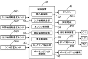
- FIG. 1 is a schematic diagram showing a schematic configuration of a vehicle drive device 2 according to the present embodiment.
- a solid line indicates a transmission path of driving force (torque)
- a broken line indicates a command pressure of hydraulic oil or a hydraulic oil supply path
- a one-dot chain line indicates an electric signal transmission path.
- the vehicle drive device 2 schematically includes an engine E and a rotating electrical machine MG as a driving force source 13, a torque converter 14 as a fluid coupling, and a transmission TM. And a control device 31 that controls at least the driving force source 13 and the transmission device TM, and the rotation of the input shaft I as a drive input member driven by these driving force sources 13 is changed via the torque converter 14.
- the transmission is transmitted to the intermediate shaft M as an input member, and the rotation of the transmission input member is shifted by the transmission TM and transmitted to the output shaft O as an output member.
- the vehicle drive device 2 includes a hydraulic control device PC that is controlled by the control device 31 and supplies a command pressure of hydraulic oil to each hydraulic operation unit such as the transmission TM, the torque converter 14, and the transmission clutch TC. ing.
- the vehicle drive device 2 includes an input shaft rotational speed sensor Se1, an intermediate shaft rotational speed sensor Se2, and an output rotational speed sensor Se3 that detect rotational speeds of the input shaft I, the intermediate shaft M, and the output shaft O. Further, the vehicle drive device 2 includes a shift position sensor Se4 that detects a selection position (hereinafter referred to as “shift position”) of the shift lever SL as a switching operation unit that receives an operation of switching the state of the transmission apparatus TM. . The outputs of the sensors Se1 to Se4 are input to the control device 31. In the present embodiment, the “P (parking) range”, “R (reverse) range”, “N (neutral) range”, and “D (drive) range” can be selected by the shift lever SL.
- “P range” and “N range” correspond to the non-transmission state in the present invention because the rotation of the intermediate shaft M is not transmitted to the output shaft O, and “D range” and “R range”. Corresponds to the transmission state in the present invention because the rotation of the intermediate shaft M is transmitted to the output shaft O.
- the control device 31 Based on the shift position detected by the shift position sensor Se4, the control device 31 switches at least between the transmission state (D and R ranges here) and the non-transmission state (here P and N ranges) of the transmission device TM. .
- the vehicle drive device 2 includes a parking lock mechanism PR as a lock mechanism that can switch between a rotation fixed state in which the rotation of the output shaft O as an output member is mechanically fixed and a fixed release state in which the fixation is released.
- the control device 31 performs switching between the rotation fixed state and the fixed release state.
- the vehicle drive device 2 includes an engine E and a rotating electrical machine MG as a drive power source 13 for driving the vehicle, and the engine E and the rotary electrical machine MG are connected to each other.
- This is a drive device for a parallel hybrid vehicle connected in series via a transmission clutch TC.
- the engine E is an internal combustion engine that is driven by the combustion of fuel.
- various known engines such as a gasoline engine and a diesel engine can be used.
- the rotating electrical machine MG can perform a function as a motor (electric motor) that generates power upon receiving power supply and a function as a generator (generator) that generates power upon receiving power supply. ing.
- rotating electrical machine MG is electrically connected to a power storage device such as a battery or a capacitor (not shown).
- the rotor of the rotating electrical machine MG is configured to rotate integrally with the input shaft I.
- a transmission clutch TC for selectively connecting the engine E to the input shaft I is provided between the engine E and the rotating electrical machine MG.
- the transmission clutch TC operates upon receiving supply of hydraulic oil command pressure from the hydraulic control device PC.
- Transmission clutch In the vehicle drive device 2 of the present embodiment, when the vehicle starts or runs at a low speed, the transmission clutch TC is released, the engine E is stopped, and only the driving force of the rotating electrical machine MG is applied to the wheels 18. It is transmitted and travels. At this time, rotating electrical machine MG receives a supply of electric power from a power storage device (not shown) and generates a driving force.
- the engine E is cranked and started when the transmission clutch TC is engaged while the rotational speed of the rotating electrical machine MG is equal to or greater than a certain value. After the engine E is started, the driving force of both the engine E and the rotating electrical machine MG is transmitted to the wheels 18 to travel.
- the rotating electrical machine MG can be either in a state where power is generated by the driving force of the engine E or in a state where driving force is generated by the power supplied from the power storage device, depending on the state of charge of the power storage device (not shown).
- the transmission clutch TC is released, the engine E is stopped, and the rotating electrical machine MG is in a state of generating electric power by the driving force transmitted from the wheels 18.
- the electric power generated by the rotating electrical machine MG is stored in a power storage device (not shown).
- the transmission clutch TC is released, the engine E is stopped, and only the driving force of the rotating electrical machine MG can be transmitted to the transmission TM via the torque converter 14.
- the vehicle drive device 2 also includes a torque converter 14 and a transmission TM for transmitting the driving force from the driving force source 13 to the wheel 18 side.
- the speed change device TM is a device that is provided between the driving force source 13 and the wheel 18 and shifts the driving force from the driving force source 13 transmitted through the torque converter 14 and transmits it to the wheel 18 side.
- the torque converter 14 is a device that is provided between the driving force source 13 and the transmission device TM and transmits the driving force of the input shaft I to the transmission device TM via the intermediate shaft M.
- the torque converter 14 corresponds to a fluid coupling in the present invention.
- the torque converter 14 is provided between a pump impeller 14a as an input side rotating member connected to the input shaft I, a turbine runner 14b as an output side rotating member connected to the intermediate shaft M, and a one-way clutch.
- the stator 14c provided with.
- the torque converter 14 transmits the driving force between the input side (drive side) pump impeller 14a and the output side (driven side) turbine runner 14b via hydraulic oil filled therein. For this reason, a torque difference and a rotational speed difference usually occur between the drive side and the driven side rotary shafts.
- the torque converter 14 includes a lockup clutch LC as a friction engagement means for lockup.
- the lock-up clutch LC is a clutch that connects the pump impeller 14a and the turbine runner 14b so as to rotate together to eliminate the differential rotation (slip) between the pump impeller 14a and the turbine runner 14b and increase transmission efficiency. It is.
- the torque converter 14 transmits the driving force of the driving force source 13 (input shaft I) directly to the transmission device TM (intermediate shaft M) without using hydraulic fluid. There is no torque difference or rotational speed difference between the drive-side and driven-side rotary shafts.
- This lock-up clutch LC operates upon receiving supply of hydraulic oil command pressure from the hydraulic control device PC.
- the lockup clutch LC is released when the transmission stage of the transmission TM is switched, and the driving force is transmitted via the hydraulic oil.
- the lock-up clutch LC is released, and the driving force is transmitted via the hydraulic oil.
- the lockup clutch LC is brought into an engaged state after completion of switching to the starting shift stage (first speed stage in this example) of the transmission TM. The vehicle is started by the driving force of the rotating electrical machine MG.
- the transmission TM includes a plurality of transmission rotation elements and at least one friction engagement element, and transmits the rotation of the intermediate shaft M to the output shaft O when the friction engagement element is engaged. When the friction engagement element is in the released state, the rotation of the intermediate shaft M is not transmitted to the output shaft O.
- the transmission TM of the present embodiment is a stepped automatic transmission having a plurality of shift stages with different gear ratios.
- the transmission TM has gears such as a planetary gear mechanism such as a planetary gear mechanism serving as a rotation element for transmission, a rotation member such as a rotation shaft, a bearing, and a hub, and a friction engagement element.
- Friction engagement elements such as a clutch and a brake are provided.
- the friction engagement elements are engagement elements each having a friction material.
- the rotation element for shifting includes a drum, a hub, a piston, a friction material, and the like that constitute a friction engagement element.
- FIG. 1 schematically shows a first clutch C1 as an example of a friction engagement element.
- Each friction engagement element of the transmission TM operates by receiving a command pressure of hydraulic oil from the hydraulic control device PC. Then, by selectively switching engagement or disengagement of the plurality of friction engagement elements, the transmission state of the driving force to the plurality of shift rotation elements included in the gear mechanism is switched, and the shift stage is switched. . In a state where any one of the gear positions is formed, the transmission device TM is in a transmission state in which the rotation of the intermediate shaft M is transmitted to the output shaft O. On the other hand, by setting all the friction engagement elements to the released state, the transmission apparatus TM enters a non-transmission state in which the rotation of the intermediate shaft M is not transmitted to the output shaft O.
- the transmission apparatus TM shifts the rotational speed of the intermediate shaft M at a predetermined speed ratio set for each shift speed, converts the torque, and transmits the torque to the output shaft O. Then, the driving force transmitted from the transmission device TM to the output shaft O is transmitted to the wheels 18 via the differential device 17.
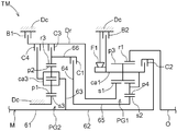
- FIG. 3 is a skeleton diagram of the transmission apparatus TM according to the present embodiment.
- the transmission apparatus TM includes a planetary gear device that is a combination of two sets of differential gear devices PG1 and PG2.
- the transmission TM includes a plurality of friction engagement elements C1, C2, C3, C4, B1, B2, and F1 corresponding to the rotating elements constituting the planetary gear device.
- the transmission apparatus TM includes a first clutch C1, a second clutch C2, a third clutch C3, a fourth clutch C4, a first brake B1, a second brake B2, and one friction engagement element.
- a direction clutch F1 is provided.
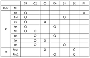
- FIG. 4 is a diagram showing an operation table of these friction engagement elements C1, C2, C3, C4, B1, B2, and F1.
- “ ⁇ ” indicates that each friction engagement element is in an engaged state.
- “No mark” indicates that each friction engagement element is in a released state.
- “ ⁇ ” indicates that the one-way clutch F1 operates.
- the transmission apparatus TM any two friction engagement elements are brought into an engagement state at each shift stage, and the remaining friction engagement elements are brought into a disengagement state. Select the gear position.
- “1st” is the first speed
- “2nd” is the second speed
- “3rd” is the third speed
- “4th” is the fourth speed
- “5th” is the fifth speed
- “6th” indicates the sixth speed
- “7th” indicates the seventh speed
- “8th” indicates the eighth speed
- “Rev1” indicates the first reverse speed
- “Rev2” indicates the second reverse speed.
- the first speed stage, the second speed stage,..., The eighth speed stage are set in order from the largest gear ratio when the rotation of the intermediate shaft M is transmitted to the output shaft O. This also applies to the reverse gear, and the reverse first speed and the reverse second speed are set in order from the largest gear ratio.
- the first speed stage (1st) to the eighth speed stage (8th) are selected by the control device 31 when “D range” is selected as the shift position.
- the reverse first speed (Rev1) and the reverse second speed (Rev2) are selected by the control device 31 when the “R range” is selected as the shift position.
- P range” or “N range” is selected as the shift position, as shown in FIG. 4, all the friction engagement elements are released.
- such a state of the transmission apparatus TM is set to a neutral stage (Ntl) for convenience.
- the neutral stage (Ntl) is selected in the “P range” or the “N range”
- the transmission device TM is in a non-transmission state.
- the transmission TM is in a transmission state.
- the shift lever SL is operated to change from the “P range” or “N range” (non-transmission state) to the “D range”.
- “(Transmission state) is input, the switch from the neutral stage (Ntl) to the first speed stage (1st) is performed.
- the first gear (1st) is formed only by engagement of the first clutch C1. Therefore, in this case, the first clutch C1 corresponds to at least one friction engagement element in the present invention.
- the second differential gear device PG2 is configured by a double pinion type planetary gear mechanism disposed coaxially with the intermediate shaft M. That is, the second differential gear device PG2 includes three rotating elements: a carrier ca3 that supports a plurality of sets of pinion gears, and a sun gear s3 and a ring gear r3 that respectively mesh with the pinion gears.
- the carrier ca3 of the second differential gear device PG2 is connected to rotate integrally with the intermediate shaft M, and the driving force of the intermediate shaft M is transmitted to the second differential gear device PG2.
- the sun gear s3 of the second differential gear device PG2 is fixed to the case Dc. Accordingly, the rotation elements of the second differential gear device PG2 are rotated by the rotation of the intermediate shaft M.
- the neutral stage (Ntl) in which all the friction engagement elements engaged with the second differential gear device PG2 are in the released state, the rotation of the intermediate shaft M, in particular, each rotation of the second differential gear device PG2.
- the element rotates, but no driving force is transmitted to the output shaft O.
- the first differential gear device PG1 is constituted by a Ravigneaux type planetary gear device arranged coaxially with the intermediate shaft M.
- the Ravigneaux type planetary gear device is a single pinion type planetary gear mechanism that uses a pinion gear p3 and a double pinion type planetary gear device that uses a combination of pinion gears p3 and p4.
- the pinion gear p3, carrier ca1, and ring gear r1 And is shared.
- the first differential gear device PG1 includes two sun gears, a first sun gear s1 and a second sun gear s2, a ring gear r1, a long pinion gear p3 that meshes with both the first sun gear s1 and the ring gear r1, and this Four rotating elements are provided with a common carrier ca1 that supports a short pinion gear p4 that meshes with the long pinion gear p3 and the second sun gear s2.
- the torque of the intermediate shaft M transmitted to the second differential gear device PG2 is transferred from the ring gear r3 of the second differential gear device PG2 to the first differential gear device PG1. Input to the second sun gear s2.
- the one-way clutch F1 is engaged by the driving force input to the second sun gear s2 of the first differential gear device PG1, and the second The driving force input to the sun gear s2 is transmitted from the ring gear r1 to the output shaft O via the second differential gear device PG2.
- the torque transmission path at this time constitutes the first speed stage.
- the one-way clutch F1 functions as a one-way engagement element that is engaged and is prevented from rotating when the carrier ca1 is negatively rotated, and selectively fixes the carrier ca1 to the case Dc. Stop.
- the ring gear r3 of the second differential gear device PG2 is selectively connected to the brake drum Dr and the first sun gear s1 of the first differential gear device PG1 rotating integrally therewith via the third clutch C3.
- the carrier ca3 is selectively connected via the fourth clutch C4 to the brake drum Dr and the first sun gear s1 of the first differential gear device PG1 that rotates integrally therewith.
- the brake drum Dr is a cylindrical rotating member disposed on the engine E side (left side in FIG. 3) with respect to the first differential gear device PG1, and the first brake B1 is provided on the outer periphery.
- a third clutch C3 and a fourth clutch C4 are provided on the inner periphery of the brake drum Dr, and a second differential gear device PG2 and a first clutch C1 are disposed further radially inward. ing.
- the brake drum Dr is connected to rotate integrally with the first sun gear s1 at the end on the output shaft O side.
- the first sun gear s1 is selectively fixed to the case Dc via the first brake B1.
- the first sun gear s1 is selectively connected to the ring gear r3 of the second differential gear device PG2 via the third clutch C3, and the carrier ca3 of the second differential gear device PG2 via the fourth clutch C4.
- the carrier ca1 is selectively fixed to the case Dc via the second brake B2, and is selectively connected to the intermediate shaft M via the second clutch C2.
- the one-way clutch F1 selectively fixes the carrier ca1 to the case Dc and stops it as described above.
- the first sun gear s1 of the first differential gear device PG1 is engaged with the carrier ca3 of the second differential gear device PG2 via the third clutch C3 by engaging the third clutch C3.
- the torque of the intermediate shaft M transmitted to the ring gear r3 is input.
- the torque of the intermediate shaft M is input to the first sun gear s1 through the fourth clutch C4 by engaging the fourth clutch C4.
- the torque of the intermediate shaft M is input to the carrier ca1 of the first differential gear device PG1 through the second clutch C2 by engaging the second clutch C2.
- the output shaft O has a lock mechanism capable of switching between a rotation fixed state in which the rotation of the output shaft O is mechanically fixed and a fixed release state in which the fixation is released.
- a parking lock mechanism PR is attached.
- the parking lock mechanism PR includes a parking gear (not shown) attached to the output shaft O, and a parking lock pole (not shown) that meshes with the parking gear and stops its rotational drive.
- the parking lock pole is operated by a command from the control device 31 or an operation of the shift lever SL, etc., and is engaged with and released from the parking gear so that the parking lock mechanism PR is in a rotation fixed state and a fixed release state. Switch.
- the hydraulic control device PC sucks hydraulic oil stored in an oil pan (not shown), and uses two types of mechanical pump MP and electric pump EP as hydraulic sources for supplying hydraulic oil to each part of the vehicle drive device 2. Equipped with a pump.
- the mechanical pump MP is drivingly connected to the pump impeller 14a of the torque converter 14, and is driven by the driving force of the engine E or the rotating electrical machine MG.
- the mechanical pump MP does not discharge hydraulic oil while the input shaft I is stopped (for example, when the engine E and the rotating electrical machine MG are stopped). Therefore, an electric pump EP is provided as a pump for assisting the mechanical pump MP.
- the electric pump EP is an oil pump that is driven by the driving force of the pump motor 20 and discharges hydraulic oil irrespective of the driving force of the driving force source 13.
- the pump motor 20 that drives the electric pump EP is electrically connected to a battery (not shown), and receives a supply of electric power from the battery to generate a driving force.
- the electric pump EP is a pump for assisting the mechanical pump MP, and operates in a state where a necessary amount of oil is not supplied from the mechanical pump MP while the vehicle is stopped. Therefore, if necessary, the electric pump is driven to ensure the hydraulic pressure necessary for the engagement of the friction engagement elements.
- the input shaft I is rotationally driven by the driving force source 13 and the mechanical pump MP is driven, but the rotational speed of the input shaft I is low and the amount of oil is insufficient. Also drives the electric pump EP to ensure hydraulic pressure.
- the hydraulic control apparatus PC includes a hydraulic control valve (not shown) for adjusting the hydraulic pressure of the hydraulic oil supplied from the mechanical pump MP and the electric pump EP to a predetermined pressure.
- the hydraulic control valve is controlled from the regulating valve by adjusting the opening of one or more regulating valves based on a signal pressure from a linear solenoid valve for hydraulic regulation (not shown).
- the hydraulic oil pressure is adjusted to a predetermined pressure by adjusting the amount of draining hydraulic oil.
- the hydraulic oil adjusted to a predetermined pressure has a required level of hydraulic pressure, and the transmission clutch TC, the lockup clutch LC, and the plurality of friction engagement elements C1, C2, C3, C4, B1, B2 is supplied.
- the hydraulic oil is also used for lubrication and cooling of the gears, shafts, bearings, and other parts of the first differential gear device PG1 and the second differential gear device PG2, which are rotational elements for transmission of the transmission TM. Supplied to these sites.
- the mechanical pump MP and the electric pump EP are driven as described above to generate hydraulic pressure, and the driving force source 13 rotates the intermediate shaft M via the torque converter 14, By rotating each shifting rotary element of the transmission TM, lubricating oil can be supplied to the rotating elements such as bearings and gears of the transmission TM to form an oil film.
- the control device 31 included in the vehicle drive device 2 functions as a core member that controls the operation of each part of the vehicle drive device 2.
- the control device 31 includes functions of an alignment control unit 32, an input information detection unit 33, an engine control unit 34, a rotating electrical machine control unit 35, a transmission control unit 36, a lockup control unit 37, and a parking lock control unit 38. Department.
- the alignment control unit 32 performs a series of alignment control
- the other functional units are integrated and controlled.
- each of the other functional units performs normal control.
- each structure of the control apparatus 31 is demonstrated in detail.
- the control device 31 includes an arithmetic processing device such as a CPU as a core member, and also includes a RAM (random access memory) configured to be able to read and write data from the arithmetic processing device, and an arithmetic processing device.
- a ROM read only memory
- a storage device such as a memory are included (not shown).
- the functional units 32 to 38 of the control device 31 are configured by software (program) stored in a ROM or the like, hardware such as a separately provided arithmetic circuit, or both. Each of these functional units 32 to 38 is configured to be able to exchange information with each other.
- the vehicle drive device 2 includes a plurality of sensors provided in each part as described above, that is, an input shaft rotational speed sensor Se1, an intermediate shaft rotational speed sensor Se2, An output rotation speed sensor Se ⁇ b> 3, a shift position sensor Se ⁇ b> 4, and the like are provided, and input information from various sensors is input to the control device 31.
- the control device 31 also outputs electrical signals that control the engine E, the rotating electrical machine MG, the hydraulic control device PC, the pump motor 20, the parking lock mechanism PR, and the like.
- the input information detection unit 33 is a functional unit that detects input information such as the various sensors connected to the control device 31. Each function unit of the control device 31 executes various operation processes using each detection value detected by the input information detection unit 33.
- the input shaft rotational speed sensor Se1 is a sensor that detects the rotational speed of the input shaft I.
- the rotation speed detected by the input shaft rotation speed sensor Se1 is the rotation speed of the rotating electrical machine MG and is the rotation speed on the input side of the torque converter 14.
- the intermediate shaft rotation speed sensor Se2 is a sensor that detects the rotation speed of the intermediate shaft M.
- the rotational speed detected by the intermediate shaft rotational speed sensor Se2 is the rotational speed on the output side of the torque converter 14, and is the rotational speed on the input side of the transmission apparatus TM.
- the output shaft rotation speed sensor Se3 is a sensor that detects the rotation speed of the output shaft O.
- the rotational speed detected by the output shaft rotational speed sensor Se3 is the rotational speed on the output side of the transmission apparatus TM. Further, since the rotational speed is proportional to the vehicle speed, the input information detection unit 33 can detect the vehicle speed based on the rotational speed.
- the shift position sensor Se4 is a sensor for detecting the selection position (shift position) of the shift lever SL.
- the “P range”, “R range”, “N range”, and “D range” can be selected by the shift lever SL. Therefore, from the shift position sensor Se4, a value indicating whether “P range”, “R range”, “N range”, or “D range” is selected as the detected value of the shift position is detected as input information. Input to the unit 33. Based on the input information from the shift position sensor Se4, the input information detection unit 33 determines which range of “P”, “N”, “D”, and “R” is designated by the driver, that is, It is detected which state command is made.
- the input information detection unit 33 determines that there has been a state transition command.
- “P range” and “N range” are state commands for setting the transmission device TM to the non-transmission state
- “D range” and “R range” are state commands for setting the transmission device TM to the transmission state. is there. Therefore, when the shift position is switched from “P range” or “N range” to “D range” or “R range”, the input information detection unit 33 of the control device 31 is changed from the non-transmission state to the transmission state. A state transition command is input.
- the engine control unit 34 is a functional unit that controls the operation of the engine E.
- the engine control unit 34 determines the engine operating point, or is instructed by another functional unit such as the alignment control unit 32, and performs processing for controlling the engine E to operate at the engine operating point.
- the engine operating point is a control command value representing a control target point of the engine E, and is determined by the rotational speed and torque. More specifically, the engine operating point is a command value that represents a control target point of the engine E that is determined in consideration of the vehicle required output (determined based on the vehicle required torque and the engine rotational speed). It is determined by the value and torque command value.
- the engine control unit 34 controls the engine E so as to operate at the torque and the rotational speed indicated by the engine operating point.
- the engine operating point also includes control command values for starting and stopping the engine E.
- start control command value the engine control unit 34 starts the engine E by executing a start sequence such as supplying fuel for starting.
- stop control command value the engine control unit 34 executes a stop sequence such as shutting off the fuel supply and stopping the engine E.
- the engine control unit 34 is configured to perform idle stop control that shuts off the fuel supply to the engine E and stops the engine E when a predetermined idle stop condition is satisfied.
- the engine E is maintained in a stopped state in a state where the vehicle can be driven with the main power source turned on. That is, the engine E is maintained in a stopped state while the vehicle is traveling, or the engine E is maintained in a stopped state while the vehicle is stopped.
- the idle stop condition is determined in advance in this example based on the rotational speed of the engine E, the accelerator opening, the vehicle speed, and the like.
- the vehicle is stopped (the vehicle speed is zero), or the output of the engine E is decreased when the vehicle is in a coast state (the rotational speed of the engine E is decreased when the accelerator opening is equal to or less than a predetermined value).
- the engine control unit 34 also performs control to restart the engine E by restarting the fuel supply to the engine E when the idle stop condition is no longer satisfied. Such control is also included in the above-described idle stop control.
- Rotating electrical machine control unit 35 is a functional unit that controls the operation of the rotating electrical machine MG.
- the rotating electrical machine control unit 35 determines the rotating electrical machine operating point or is instructed by another functional unit such as the alignment control unit 32 to operate the rotating electrical machine MG at the rotating electrical machine operating point.
- the rotating electrical machine operating point is a control command value representing a control target point of the rotating electrical machine MG, and is determined by the rotational speed and torque. More specifically, the rotating electrical machine operating point is a command value representing a control target point of the rotating electrical machine MG determined in consideration of the vehicle required output and the engine operating point, and is based on the rotational speed command value and the torque command value. Determined.
- the rotating electrical machine control unit 35 controls the rotating electrical machine MG so as to operate at the torque and the rotational speed indicated by the rotating electrical machine operating point.
- the rotating electrical machine control unit 35 generates a driving force for the rotating electrical machine MG with the electric power supplied from the battery according to the amount of charge of the battery detected by a battery state detection sensor (not shown), Control is also performed to switch between the state in which the rotating electrical machine MG generates power using the driving force.
- the rotating electrical machine control unit 35 is also configured to control the rotational speed of the pump motor 20 for driving the electric pump EP.
- Shift control unit The shift control unit 36 determines a target gear position in the transmission TM based on the accelerator opening, the vehicle speed, and the shift position of the vehicle during normal control, and each friction engagement in the transmission TM. This is a functional unit that performs gear shifting by instructing engagement or disengagement of elements. In order to determine such a target shift speed, the shift control unit 36 refers to a shift map (not shown) stored in the ROM or the like and determines the target shift speed. Then, the shift control unit 36, based on the operation table as shown in FIG.
- each engagement element C1, C2, C3, C4, B1, B2 By controlling the engagement or disengagement operation, control for switching the gear position of the transmission apparatus TM is performed. That is, the shift control unit 36 sets the hydraulic oil set to the engagement elements selected according to the determined target shift speed as a normal control through the hydraulic control device PC according to the command pressure setting sequence. The command pressure is supplied to bring the engagement element into an engaged state or a released state, and control for realizing the target shift stage is performed.
- the shift control unit 36 determines the target shift speed from the first speed (1st) to the eighth speed (8th), When “R range” is selected, the shift control unit 36 determines the target shift speed from among the reverse first speed (Rev1) and the reverse second speed (Rev2). When “P range” or “N range” is selected, the shift control unit 36 determines the neutral speed (Ntl) as the target speed. When the neutral speed (Ntl) is set as the target speed, the speed change control unit 36 performs control to release all the engaging elements C1, C2, C3, C4, B1, and B2. On the other hand, as described later, when the alignment control unit 32 performs alignment control, the shift control by the transmission control unit 36 is prohibited, and the alignment control unit 32 performs the shift control.
- Lock-up control unit 37 determines a target engagement state of the lock-up clutch LC, which is a friction engagement element, based on the accelerator opening, the vehicle speed, and the shift position of the vehicle. It is a functional unit that controls engagement or release. In order to determine such a target engagement state, the lockup control unit 37 refers to a lockup map (not shown) stored in the ROM or the like and determines the target engagement state. Then, the lockup control unit 37 supplies the command pressure of the set hydraulic oil to the lockup clutch LC through the hydraulic control device PC according to the command pressure setting sequence according to the determined target engagement state. Then, control is performed to bring the lockup clutch LC into an engaged state or a released state. On the other hand, when alignment control is being performed by the alignment control unit 32, as will be described later, the alignment control unit 32 instructs the lockup control unit 37 to release the lockup clutch LC and locks it. Control is performed to release the up-clutch LC.
- the parking lock control unit 38 is a functional unit that performs switching control between a rotation fixed state and a fixed release state of the parking lock mechanism PR. Normally, when a state command designating “P range” is input to the input information detection unit 33, the parking lock control unit 38 controls the parking lock mechanism PR to be in a rotation fixed state. When a state command specifying “N range”, “D range”, and “R range” other than “P range” is input to the input information detection unit 33, the parking lock control unit 38 The parking lock mechanism PR is controlled to be in a fixed release state. On the other hand, when alignment control is performed by the alignment control unit 32, the parking lock control unit 38 releases the parking lock mechanism PR in accordance with a command from the alignment control unit 32, as will be described later. Control to make a state.
- the alignment control unit 32 is configured to output a plurality of signals in the transmission device TM when a state transition command from the non-transmission state to the transmission state is input in a state where the driving force source 13 is not generating the driving force. A centering operation for adjusting the position of the rotational axis of at least a part of the rotating element for shifting is performed.
- the alignment control unit 32 is a characteristic functional unit of the present embodiment. Here, the alignment operation is performed by causing the driving force source 13 to generate a driving force while maintaining the non-transmission state before engaging at least one friction engagement element of the transmission apparatus TM and shifting to the transmission state.
- the alignment operation corresponds to the “shift input rotation operation” in the present invention.
- the alignment control unit 32 operates the function units of the control device 31 in an integrated manner in order to realize this function.
- an oil clearance is provided between the rotating elements for transmission of the transmission device TM, specifically, between the gear coupling of the planetary gear device, between the bearing members such as bushes, etc. in order to form an oil film and move it smoothly.
- the rotational axis of each speed change rotary element is eccentric, and the eccentric axes do not coincide with each other.
- the rotational elements for shifting that are eccentric to each other are engaged by the friction engagement elements, the rotational axes are fixed in a state of being eccentric from each other. Even if the transmission rotation element is rotated in this eccentric fixed state, the oil clearance is not recovered, and there is a possibility that each transmission rotation element may be worn out or an abnormal noise may be generated from the transmission TM. .
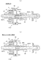
- FIG. 5 (a) schematically shows an example of the transmission TM shown in FIG. 3 in a state where the rotational axis of each transmission rotary element around the first clutch C1 is eccentric.
- the shaft members 61 and 62 constituting the intermediate shaft M are spline-fitted between the two members, and play is provided in the spline fitting, so that the shaft center near the middle is caused by its own weight. It is bent downward with respect to X.
- the pinion gear p2 and the carrier ca3 (63) of the second differential gear device PG2 which is a double pinion type planetary gear mechanism, have their axes decentered by their own weight by the oil clearance.
- a bush-shaped bearing is provided between the cylindrical member 65 and the intermediate shaft M (62), and an oil clearance is provided.
- FIG. 5 (b) shows the situation when the speed change input member (intermediate shaft M) is rotated and each speed change rotation element is rotated with the first clutch C1 engaged in an eccentric state.
- the lubricating oil is supplied to the oil clearance except for the eccentrically engaged first clutch C1, and the bias due to the oil weight's own weight is recovered and rotated.
- the eccentricity of the shaft center has been eliminated.
- the first clutch C1 is eccentrically engaged, as shown in FIG. 5B, the clearance between the cylindrical member 65 and the intermediate shaft M (62) has not recovered. For this reason, these relatively rotating members may come into contact with each other, and uneven wear may occur or abnormal noise may occur.
- the shifting input member (intermediate shaft M) is rotated, and the alignment operation is performed to rotate each shifting rotation element.
- the shifting input member intermediate shaft M
- the alignment operation is performed to rotate each shifting rotation element.
- lubricating oil is supplied to the oil clearance, and the bias due to the weight of the oil clearance can be recovered. Therefore, the eccentricity of the rotation axis and the eccentricity of the first clutch C1 can be eliminated.
- the intermediate shaft M (62) rotates also in the clearance between the cylindrical member 65 and the intermediate shaft M (62), lubricating oil is supplied and the clearance is recovered. Then, by engaging the first clutch C1 after performing such an alignment operation, the above-described problems can be suppressed.
- the rotation of the input shaft I due to the driving force of the rotating electrical machine MG is transmitted to the intermediate shaft M (62) via the torque converter 14.
- the torque converter 14 Since the input side has a rotational speed difference with respect to the output side of the motor, it is suppressed that the rotation of the input shaft I is directly transmitted to the intermediate shaft M (62), and is transmitted to the output shaft O via the transmission TM. Variations in the transmitted driving force can be suppressed.
- the alignment control unit 32 satisfies the alignment control start condition when a state transition command from the non-transmission state to the transmission state is input in a state where the driving force source 13 is not generating the driving force. And a series of alignment control of alignment operation and engagement is started.
- the driving force source 13 is the engine E and the rotating electrical machine MG, and this corresponds to a state in which neither driving force source 13 generates a driving force. More specifically, the engine E is in a stopped state, and the rotating electrical machine MG is in a rotation stopped state and a state where no torque is generated.
- the state command detected by the shift position sensor Se4 changes from “P range” or “N range” corresponding to the non-transmission state to “D range” or “R range” corresponding to the transmission state.
- the input information detection unit 33 detects a state transition command from the non-transmission state to the transmission state.
- FIG. 6 time t11
- a state transition command for detecting a state transition from the “P range” corresponding to the non-transmission state to the “D range” corresponding to the transmission state is detected. Will be described as an example.
- each control unit 34 determines that the alignment control start condition is satisfied
- the control mode of each control unit 34 to 38 is changed from the normal control mode to alignment. Switch to control mode.
- the engine control unit 34 controls the engine E according to only the engine operating point commanded from the alignment control unit 32.
- the alignment control unit 32 since the alignment operation is performed by the rotational drive of the rotating electrical machine MG, the alignment control unit 32 issues a command to stop the engine E and prohibits the start and operation of the engine E.
- the alignment control unit 32 issues a command to put the transmission clutch TC in the released state, and the control device 31 controls the transmission clutch TC to the released state.
- the transmission clutch TC is controlled via the hydraulic control device PC.
- the rotating electrical machine control unit 35 controls the rotating electrical machine MG in accordance with the rotating electrical machine operating point commanded from the alignment control unit 32.
- the alignment control unit 32 instructs the rotating electrical machine operating point in which the value of the target rotational speed is set as will be described later, and the rotating electrical machine control is performed.
- the rotating electrical machine MG is controlled via the unit 35.
- the alignment control unit 32 prohibits the transmission control unit 36 from controlling the transmission device TM and switches to the control of the transmission device TM by the alignment control unit 32.
- the lockup control unit 37 controls the lockup clutch LC according to the target engagement state commanded from the alignment control unit 32. In the present embodiment, since rotation and driving force are transmitted via the torque converter 14, the alignment control unit 32 instructs the lockup control unit 37 to release the lockup clutch LC, and locks the lockup control unit 37. Engagement of the up clutch LC is prohibited.
- the parking lock control unit 38 controls the state of the parking lock mechanism PR in accordance with a command from the alignment control unit 32.
- the alignment control unit 32 instructs the parking lock control unit 38 to set the parking lock mechanism PR to the unlocked state, and the parking lock mechanism PR is set to the unlocked state.
- the parking lock mechanism PR is set in the unlocked state before the rotating electrical machine MG generates the driving force.
- the alignment control unit 32 instructs the rotating electrical machine control unit 35 to rotationally drive the pump motor 20. Thereby, the lubricating oil is supplied into the transmission device TM, and the formation of an oil film by the rotation of the rotating electrical machine MG is promoted, so that the alignment accuracy can be improved and the alignment time can be shortened. Further, the response of the hydraulic pressure supply for the engagement of the friction engagement element (for example, the first clutch C1) of the transmission apparatus TM is improved, and the engagement time can be shortened. Further, the alignment control unit 32 instructs the hydraulic control device PC to increase the hydraulic pressure of the lubricating oil supplied into the transmission device TM higher than the hydraulic pressure of the normal control.
- the alignment time can be further reduced by controlling the hydraulic pressure supply device PC in accordance with the alignment operation. Therefore, the start delay of the vehicle after the state transition is detected can be reduced, and drivability can be improved.
- the alignment control unit 32 After switching each control unit of the control device 31 to the alignment control mode, the alignment control unit 32 starts a sequence of alignment operations of alignment operation and engagement. First, the alignment control unit 32 starts rotating the rotating electrical machine MG while maintaining the non-transmission state before shifting the transmission device TM to the transmission state. In this example, as shown in FIG. 6 (time t11), when it is determined that the alignment control start condition is satisfied, the rotational drive of the rotating electrical machine MG is started. At this time, the alignment control unit 32 sets a target rotation speed of the rotating electrical machine MG and instructs the rotating electrical machine control unit 35.
- the rotating electrical machine control unit 35 changes the rotational speed of the rotating electrical machine MG from 0 to the target rotational speed in a stepwise manner after starting the rotational driving of the rotating electrical machine MG based on the target rotational speed.
- the actual rotational speed follows the step change of the target rotational speed with a delay.
- This follow-up delay can be adjusted by setting the control gain of the rotating electrical machine control unit 35.
- the alignment control unit 32 can adjust the follow-up delay by instructing a control gain to the rotating electrical machine control unit 35.
- the alignment control unit 32 receives at least one of the plurality of speed change rotary elements in the transmission apparatus TM when a predetermined time has elapsed since it was determined that the alignment control start condition was satisfied. It is determined that the alignment operation for adjusting the position of the rotation axis of the unit has been completed.
- This predetermined time is set so as to reach the time when the alignment of the rotational element for shifting is completed in consideration of variations due to various factors. In particular, it is necessary to consider the follow-up delay of the intermediate shaft M with respect to the rotational change of the input shaft I caused by passing through the torque converter 14, and the intermediate shaft M reaches a sufficient rotational speed for alignment for a predetermined time.
- the alignment control unit 32 sets the auto-decrement timer to a predetermined time (100 msec in the example shown in FIG. 6, hereinafter “timer time”) when the alignment control start condition is satisfied (time t11). )), And when the timer time has elapsed and the timer reaches 0 (time t12), it is determined that the alignment operation has been completed.
- timer time 100 msec in the example shown in FIG. 6, hereinafter “timer time”
- the timer time may be set according to the rotation stop time of the speed change rotary element of the transmission apparatus TM.
- the rotation stop time is shorter than a predetermined value, it is determined that it is not necessary to perform the alignment operation, and the normal control may be performed without performing the alignment control. In this way, an appropriate alignment time can be set according to the required time of the alignment operation that changes depending on the rotation stop time.
- the delay time from the state transition command to the start of engagement of the friction engagement element (here, the first clutch C1) can be shortened as necessary. Thereby, the start delay of a vehicle can be made small and drivability can be improved. Moreover, you may set the target rotation speed of said rotary electric machine MG according to this rotation stop time for the same reason.
- the torque conversion characteristics of the torque converter 14 change depending on the viscosity of the hydraulic oil filled in the torque converter 14, the following delay of the intermediate shaft M also changes.
- the viscosity of the lubricating oil supplied to each rotating element in the transmission apparatus TM changes depending on the oil temperature
- the period until the aligning operation is completed after the oil film is formed also changes.
- the alignment control is often performed before the engine E is warmed up, and the oil temperature is often not stable. Therefore, the timer time may be changed in accordance with any detected temperature information such as the oil temperature in the transmission TM. Since the oil viscosity increases as the oil temperature decreases, it is preferable to set the timer time longer. If it does in this way, it can respond to the completion time of alignment which changes with oil temperature. Moreover, you may set the target rotation speed of said rotary electric machine MG according to such temperature information for the same reason.
- the alignment control unit 32 satisfies at least one friction engagement element (for example, the first clutch C1) of the transmission apparatus TM as shown in FIG. 6 after such an engagement start determination condition is satisfied. ) Is controlled to be a partial engagement pressure that brings the friction engagement element into a partial engagement state.
- the engagement pressure of the friction engagement element is increased from the partial engagement pressure to bring the friction engagement element into a fully engaged state. Control to be transferred. Below, the engagement control of such a friction engagement element is demonstrated.
- At least one friction engagement element of the transmission TM to be engaged is determined.
- the case where there is a state transition command for shifting the state from the “P range” corresponding to the non-transmission state to the “D range” corresponding to the transmission state is taken as an example.
- 36 determines the target shift speed as the first speed (1st), and according to the operation table of FIG. 4, the first clutch C1 is determined as one friction engagement element to be engaged.
- start of partial engagement pressure control When the start of engagement is determined based on the engagement start determination condition, the first clutch C1, which is the friction engagement element determined above, is operated via the hydraulic control device PC. Oil is supplied to start control for partial engagement pressure.
- the partial engagement pressure is a pressure that is larger by a predetermined pressure than the stroke end pressure that is the pressure at which engagement of the first clutch C1 starts, that is, the pressure at which transmission torque capacity begins to occur.
- the alignment control unit 32 instructs the hydraulic control device PC using the partial engagement pressure as a command pressure, and supplies hydraulic oil of the command pressure to the first clutch C1.
- a command pressure that is instantaneously higher than the partial engagement pressure is set to control the start-up of the actual pressure. .
- the engagement pressure of the first clutch C1 is determined from the partial engagement pressure. Increase the first clutch C1 to the fully engaged state. As shown in the example of FIG. 6, the engagement operation of the first clutch C1 is started, the actual pressure of the first clutch C1 reaches the stroke end pressure (time t13), and then gradually increases to the partial engagement pressure. Then, the transmission torque capacity of the first clutch C1 gradually increases. As a result, the rotational speed of the intermediate shaft M changes in a direction that synchronizes with the rotational speed of the output shaft O.
- a process for detecting the minimum value of the rotational speed difference detected from the time when monitoring of the rotational speed difference is started until the present time is performed, and a predetermined value is set as the minimum value of the rotational speed difference.
- the added value is set as the predetermined determination value. More specifically, in calculating the minimum value of the rotational speed difference, the rotational speed difference at the start of monitoring is set as the initial minimum rotational speed difference, and thereafter, the rotational speed difference updated last time is set. The minimum value is compared with the rotation speed difference calculated this time, and the smaller value is updated as the minimum value of the rotation speed difference.
- the determination of the completion of the partial engagement pressure control that detects the increase in the rotational speed difference between the input shaft I and the intermediate shaft M via the torque converter 14 determines the driving force generated by the rotating electrical machine MG. Stop generation.
- the same condition as the partial engagement pressure control completion determination condition is set as the rotating electrical machine drive stop condition for stopping the driving of the rotating electrical machine MG. Therefore, as shown in FIG. 6, the alignment control unit 32 stops the driving of the rotating electrical machine MG when it is determined that the partial engagement pressure control is completed (time t14). At this time, the alignment control unit 32 sets the target rotation speed of the rotating electrical machine MG to 0 and commands the rotating electrical machine control unit 35.
- the rotating electrical machine control unit 35 changes the rotational speed of the rotating electrical machine MG to 0 in a stepwise manner based on the target rotational speed.
- the actual rotation speed of the rotating electrical machine MG changes with a delay with respect to the target rotation speed that has changed stepwise.
- the alignment control unit 32 can adjust the follow-up delay by commanding a control gain to the rotating electrical machine control unit 35. Further, the control gain may be different depending on whether the rotational speed of the rotating electrical machine MG is increased or decreased.
- the engagement pressure of the first clutch C1 is partially Control is performed to increase the engagement pressure to shift the first clutch C1 to the fully engaged state.
- the command pressure of the hydraulic oil is gradually increased from the partial engagement pressure to the complete engagement pressure from the time point when the partial engagement pressure control is completed (time t14), and reaches the complete engagement pressure. At this point, the engagement control related to the alignment control is terminated.
- the command pressure is increased from the partial engagement pressure at a predetermined change rate after the partial engagement pressure control completion determination time (time t ⁇ b> 14).
- time t ⁇ b> 14 In proportion to the increase in the hydraulic pressure, the transmission torque capacity increases, and the rotational speed difference between the input and output members of the first clutch C1 decreases. Then, it is determined that the fully engaged state is reached when the rotational speed difference becomes 0, and the command pressure is increased stepwise to the fully engaged pressure.
- the driving force of the rotating electrical machine MG is reduced as described above, and driving is performed between the input shaft I and the intermediate shaft M via the torque converter 14.
- the rotation speed of the intermediate shaft M gradually matches the rotation speed of the output shaft O as the engagement pressure of the first clutch C1 increases.
- the rotational speed of the intermediate shaft M gradually decreases toward zero. Therefore, in the present embodiment, when the rotational speed of the intermediate shaft M is equal to or lower than the predetermined determination value, it is determined that the fully engaged state is achieved.
- the predetermined determination value is set to 0, and when the rotation speed of the intermediate shaft M becomes 0, it is determined that the fully engaged state is reached (time t15). Then, the command pressure is increased stepwise up to the complete engagement pressure, and the engagement control related to the alignment control is finished.
- the alignment control unit 32 determines whether the alignment control start condition is satisfied as described above (step # 11).
- step # 11 Yes
- the process of switching each control unit to the alignment control mode is performed as described above (step # 12).
- production of the driving force of the rotary electric machine MG is performed (step # 13).
- the alignment completion determination condition (engagement start determination condition) is established, and it is determined whether alignment is complete (step # 14).
- step # 14 When the alignment completion determination condition is satisfied (step # 14: Yes), the process for starting the partial engagement control is performed as described above (step # 15). Thereafter, as described above, it is determined whether the partial engagement pressure control is completed based on the increase in the rotational speed difference between the drive input member and the shift input member, and whether the partial engagement pressure control is completed (step) # 16).
- step # 16: Yes the process of stopping the driving force generation of the rotating electrical machine MG is performed as described above (step # 17).
- step # 18 processing for starting complete engagement control is performed (step # 18).
- step # 19 When the completion condition is satisfied (step # 19: Yes), as described above, the process of returning each control unit to the normal control is performed (step # 20), and the series of alignment control is finished.
- the alignment control unit 32 performs alignment completion determination (engagement start determination) based on the elapsed time (timer time) after the start of alignment control.
- the alignment control unit 32 is different in that alignment determination is performed based on the rotation speed of the intermediate shaft M.
- the alignment control unit 32 stops the generation of the driving force of the driving force source 13 and starts the complete engagement control by measuring the rotational speed difference between the input shaft I and the intermediate shaft M.
- the alignment control unit 32 stops the generation of the driving force of the driving force source 13 based on the time point when the rotational speed of the driving force source 13 reaches the determination value.
- the difference is that the start of complete engagement control is determined by the elapsed time from the point of determination of engagement start.
- Other configurations can be the same as those of the first embodiment. Accordingly, differences from the first embodiment will be described below.
- Alignment control unit As described above, a part of the alignment control unit 32 is different between the first embodiment and the present embodiment. Accordingly, the alignment control unit 32 will be described below with a focus on the different contents.
- the alignment control unit 32 performs alignment control start determination and switching of each control unit to the alignment control mode as in the first embodiment. Thereafter, when the alignment control unit 32 determines that the alignment control start condition is satisfied, the alignment control unit 32 starts to rotate the driving force source 13. In the present embodiment, as shown in FIG. 8, the alignment control unit 32 increases the target rotation speed at a predetermined change rate from the alignment control start determination time (time t21). In this example, the alignment control unit 32 sets the rate of change to 1100 [rpm / sec], but can be changed according to each condition. In this example, a case where a rotating electrical machine MG is used as the driving force source 13 will be described as an example.
- the alignment control unit 32 can perform the alignment operation using the rotation of the rotating electrical machine MG more systematically, and the alignment accuracy is improved.
- the alignment control unit 32 rotates at least a part of the plurality of speed change rotary elements in the transmission device TM based on the rotation speed of the intermediate shaft M after determining the start of alignment control. It is determined that the alignment operation for adjusting the position of the shaft center has been completed. In this example, as shown in FIG. 8, the alignment control unit 32 determines that the alignment operation has been completed when the rotational speed of the intermediate shaft M reaches the alignment completion determination speed.
- the alignment control unit 32 determines the completion of the alignment operation based on the actual rotational speed of the intermediate shaft M, and aligns via the torque converter 14 as in the present invention. Even in this case, the alignment control unit 32 can accurately determine the alignment completion point. In the example shown in FIG. 8, the alignment control unit 32 sets the completion determination speed to 400 “rpm”, but can be changed depending on each condition.
- the alignment completion determination speed to be compared with the rotation speed of the intermediate shaft M may be set according to the rotation stop time of the transmission rotation element of the transmission apparatus TM.
- the rotation stop time is shorter than a predetermined value, it is determined that it is not necessary to perform the alignment operation, and the normal control may be performed without performing the alignment control.
- the alignment control unit 32 also uses the rotation stop time for the same reason for the rate of change of the target rotational speed of the driving force source 13 and the driving completion determination speed used for determining the stop of the driving force source 13 described later. You may set according to. Therefore, the delay time from the state transition command to the start of engagement of the first clutch C1 can be shortened as necessary. Thereby, the start delay of a vehicle can be made small and drivability can be improved.
- the alignment completion determination speed may be changed according to any detected temperature information such as the oil temperature in the transmission TM. Since the viscosity of the oil increases as the oil temperature decreases, it is preferable to set the alignment completion determination speed high.
- the alignment control unit 32 also sets the change rate of the target rotation speed of the rotating electrical machine MG and the drive completion determination speed used for determining the stop of the rotating electrical machine MG described later to such temperature information for the same reason. It may be set accordingly.
- the alignment control unit 32 determines that the target rotational speed of the rotating electrical machine MG that is increased at a predetermined change rate as described above is driven. When the determination speed is reached (time t23), it is determined to stop the generation of the driving force by the rotating electrical machine MG. Then, the alignment control unit 32 decreases the target rotation speed at a predetermined change rate from the stop determination time (time t23).
- the drive completion determination speed is set to 800 [rpm]
- the change rate is ⁇ 1100 [rpm / sec], but can be changed according to each condition as described above. Further, the alignment control unit 32 may change the rate of change between when the rotational speed of the rotating electrical machine MG is increased and when it is decreased.
- the alignment control unit 32 may set the stop determination time as a time after a predetermined time has elapsed since the target rotation speed of the rotating electrical machine MG reaches a predetermined determination value. More preferably, the speed is maintained at the drive completion determination speed.
- the alignment control unit 32 starts control for shifting the transmission apparatus TM from the non-transmission state to the transmission state. Therefore, the alignment completion determination is also an engagement start determination.
- the method for determining the start of complete engagement control is different from that in the first embodiment, and other configurations are the same as those in the first embodiment.
- the alignment control unit 32 automatically ends the control of the partial engagement pressure when a predetermined time has elapsed from the time point of the start of engagement, and complete engagement. Start the joint control.
- the alignment control unit 32 does not need to wait for the start of complete engagement control until the rotational speed difference between the input shaft I and the intermediate shaft M is detected, and until the engagement is completed. Can be shortened. This is because, as described above, the alignment control unit 32 can increase and decrease the target rotation speed of the rotating electrical machine MG at a predetermined change rate and set the rotation speed of the rotating electrical machine MG in a stable and planned manner. This is because the operation can be set systematically.
- the alignment control unit 32 ends the alignment operation and engagement, so that each control unit switched to the alignment control mode as described above returns to the normal control mode. A process is performed and a series of alignment control is complete
- the alignment control unit 32 performs a process for determining whether the alignment control start condition is satisfied as in the first embodiment (step # 21).
- the alignment control unit 32 performs a process of switching each control unit to the alignment control mode (step # 21). # 22).
- the alignment control unit 32 performs processing for starting generation of the driving force of the rotating electrical machine MG as described above (step # 23).
- the alignment control unit 32 performs a process of automatically stopping the generation of the driving force of the rotating electrical machine MG after the target rotational speed is increased as described above. After that, the alignment control unit 32 determines whether alignment is completed and alignment is completed based on the rotation speed of the intermediate shaft M as described above (step S3). # 24). When it is determined that the alignment completion determination condition is satisfied (step # 24: Yes), the alignment control unit 32 starts the partial engagement pressure control as described above, and after a predetermined time has elapsed. Then, processing for starting engagement control, which is control for starting complete engagement control, is performed (step # 25). Thereafter, as in the first embodiment, the alignment control unit 32 determines whether the complete engagement state completion determination condition is satisfied and complete engagement is completed (step # 26). When the completion determination condition is satisfied (step # 26: Yes), the alignment control unit 32 performs a process of returning each control unit to normal control as described above (step # 27), and a series of adjustments are performed. End cardiac control.
- the vehicle drive device 2 for a hybrid vehicle including the engine E and the rotating electrical machine MG as the driving force source 13 is taken as an example, and the rotating electrical machine MG is rotationally driven to perform the alignment operation. Described as an example.
- the embodiment of the present invention is not limited to this. That is, in the vehicle drive device 2 for a hybrid vehicle provided with the engine E and the rotating electrical machine MG as the driving force source 13, the engine E is started and rotationally driven instead of the rotating electrical machine MG or together with the rotating electrical machine MG for alignment. It is one of the preferred embodiments of the present invention that the operation is performed.
- the control device 31 controls the transmission clutch TC to the engaged state before or after the engine E is started, and the driving force of the engine E is transmitted through the fluid coupling such as the torque converter 14. Control to be transmitted to TM.
- the control device 31 can be configured to stop the rotational drive of the engine E, similarly to the rotating electrical machine MG in each of the above embodiments.
- the control device 31 is also suitable as a configuration that shifts to the normal control mode without stopping the rotational drive of the engine E after the alignment completion determination condition is satisfied.
- the vehicle drive device 2 includes one rotating electrical machine MG
- the embodiment of the present invention is not limited thereto, and the vehicle drive device 2 is not limited thereto. It is also one of preferred embodiments of the present invention to have a configuration including a plurality of rotating electrical machines MG as the driving force source 13. In this case, part or all of the plurality of rotating electrical machines MG can be rotationally driven to perform the alignment operation. Further, as in each of the above embodiments, the vehicle drive device 2 for a hybrid vehicle provided with the engine E and the rotating electrical machine MG as the drive force source 13 may be configured not to include the transmission clutch TC. This is one of the preferred embodiments.
- the vehicle drive device 2 for a hybrid vehicle including the engine E and the rotating electrical machine MG as the drive force source 13 has been described as an example.
- the embodiment of the present invention is not limited to this. That is, it is also a preferred embodiment of the present invention that the vehicle drive device 2 includes only one of the engine E and the rotating electrical machine MG as the drive force source 13.
- the vehicle drive device 2 including only the engine E is used, the vehicle drive device 2 is applied to an idling stop vehicle, and the control device 31 stops the engine E even when the vehicle is stopped for a short time. You may do it.
- the timer time and the alignment completion determination speed for determining completion of the alignment operation which are parameters set or determined in accordance with the rotation stop time of the transmission rotation element of the transmission apparatus TM
- the rotational speed of the rotational element for speed change of the transmission TM by the idling stop that stops the engine E such as the target rotational speed of the driving force source 13, the change rate of the drive completion determination speed and the target rotational speed, and whether or not the alignment operation can be executed.
- the engine E is stopped every time the vehicle stops, such as waiting for a signal. Therefore, the effect of shortening the delay time from the state transition command to the start of engagement of the first clutch C1 is great, and the start delay of the vehicle is reduced. And drivability can be improved.
- the embodiment of the present invention is not limited to this. It is also suitable to apply the present invention to a configuration in which the control device 31 generates a state command not based on the input information of the shift position sensor Se4 or contrary to the input information of the shift position sensor Se4. In this case, the control device 31 is configured to execute the alignment operation based on the state transition command from the non-transmission state to the transmission state generated by the control device 31 as one of the preferred embodiments of the present invention. is there.
- the transmission device TM is controlled by the command from the control device 31. May be controlled in a non-transmission state. As described above, even when the state command is in the transmission state but the transmission device TM is in the non-transmission state, the transmission device TM is controlled in the transmission state by the control device 31 again. It can be included when a state transition command from a state to the transmission state is input.
- the first embodiment determines based on the elapsed time after the start of the aligning operation
- the second embodiment includes the shift input.
- the completion determination of the alignment operation may be performed based on the rotation speed of the speed change input member.
- the completion determination of the alignment operation is performed after the start of the alignment operation. You may do it based on time.
- control device 31 has been described as an example in which the control is performed to maintain the partial engagement pressure after the start of the engagement control and then the complete engagement control is performed.
- the embodiment of the present invention is not limited to this. That is, in the second embodiment, the full engagement control is directly performed without performing the control for setting the partial engagement pressure after the start of the engagement control. It is. In this case as well, control may be performed in which a high command pressure is instantaneously set after the start of the engagement control and the rise of the actual pressure is accelerated.
- the increase or decrease of the target rotational speed of the driving force source 13 for the alignment operation in the control device 31 of each of the above embodiments is changed stepwise in the first embodiment, and the second embodiment is The case of changing at a predetermined change rate has been described as an example.
- the embodiment of the present invention is not limited to this. That is, the increase / decrease of the target rotational speed of the driving force source 13 for the alignment operation in the control device 31 of each embodiment may be changed at a predetermined change rate in the first embodiment.
- it may be changed stepwise, and further, the increase or decrease of the target rotational speed may be an increase or decrease by any combination of a step change and a change at a predetermined change rate. It may be an increase or decrease according to an arbitrary waveform.
- the rotating electrical machine MG is used as the driving force source 13 and the rotational speed of the rotating electrical machine MG is increased or decreased at a predetermined change rate has been described as an example.
- the embodiment of the present invention is not limited to this. That is, in the second embodiment, the engine E may be used as the driving force source 13, and the rotational speed of the engine E may be increased or decreased at a predetermined rate of change. It is also preferable to increase or decrease the rotational speed of the engine E at a predetermined rate of change based on the corresponding predetermined rotational speed.
- the control device 31 has been described by taking as an example the case where the driving force stop time of the driving force source 13 is set after the completion time of the alignment operation.
- the embodiment of the present invention is not limited to this. That is, in each embodiment, the control device 31 sets the time point when the driving force generation of the driving force source 13 is stopped at the same time as the alignment operation completion determination time point or the time point when the alignment operation completion determination time point is set as a reference ( For example, it is also one of preferred embodiments of the present invention to set it as a predetermined time after the completion judgment time of the alignment operation. In this way, the generation period of the driving force of the driving force source 13 can be shortened to the minimum necessary in accordance with the period of the alignment operation.
- the transmission device TM is described as an example of a stepped automatic transmission device having the first to eighth gears.
- the embodiment of the present invention is not limited to this. That is, as described above, a plurality of speed change rotating elements and at least one frictional engagement element are provided, and when the frictional engagement element is in the engaged state, the input side rotation is transmitted to the output side. Any type of transmission may be used as long as the transmission TM is configured to be in a non-transmission state in which the rotation of the input side is not transmitted to the output side when the friction engagement element is in the released state. It is also one preferred embodiment of the present invention to use various transmissions TM such as a stepped automatic transmission having an arbitrary number of shift stages, a double clutch transmission, and an automatic control manual transmission.
- the present invention includes a driving force source, a fluid coupling, a transmission, and a control device that controls at least the driving force source and the transmission, and a drive input member driven by the driving force source is rotated.
- the present invention can be suitably used for a vehicle drive device that is transmitted to the transmission input member via the fluid coupling, and the rotation of the transmission input member is shifted by the transmission and transmitted to the output member.
- E Engine (drive power source) MG: Rotating electric machine (drive power source) TM: Transmission C1: First clutch (friction engagement element, speed changing rotary element) TC: Transmission clutch PC: Hydraulic control device I: Input shaft (drive input member) M: Intermediate shaft (shift input member, shift rotating element) O: Output shaft (output member) Se1: Input shaft rotational speed sensor Se2: Intermediate shaft rotational speed sensor Se3: Output shaft rotational speed sensor Se4: Shift position sensor PR: Parking lock mechanism PG2: Second differential gear device (shifting rotational element) 2: Vehicle drive device 13: Driving force source 14: Torque converter (fluid coupling) 31: control device 32: alignment control unit 33: input information detection unit 34: engine control unit 35: rotating electrical machine control unit 36: shift control unit 37: lockup control unit 38: parking lock control unit
Landscapes
- Engineering & Computer Science (AREA)
- Chemical & Material Sciences (AREA)
- Combustion & Propulsion (AREA)
- Mechanical Engineering (AREA)
- Transportation (AREA)
- General Engineering & Computer Science (AREA)
- Automation & Control Theory (AREA)
- Hybrid Electric Vehicles (AREA)
- Electric Propulsion And Braking For Vehicles (AREA)
- Control Of Transmission Device (AREA)
- Gear-Shifting Mechanisms (AREA)
Abstract
Description
本発明の第一の実施形態について図面に基づいて説明する。本実施形態においては、本発明に係る制御装置31を、ハイブリッド車両の車両用駆動装置2に適用する場合を例として説明する。図1は、本実施形態に係る車両用駆動装置2の概略構成を示す模式図である。なお、図1において、実線は駆動力(トルク)の伝達経路を示し、破線は作動油の指令圧又は作動油の供給経路を示し、一点鎖線は電気信号の伝達経路を示している。この図に示すように、本実施形態に係る車両用駆動装置2は、概略的には、駆動力源13としてのエンジンE及び回転電機MGと、流体継手としてのトルクコンバータ14と、変速装置TMと、少なくとも駆動力源13及び変速装置TMの制御を行う制御装置31を備え、これらの駆動力源13により駆動される駆動入力部材としての入力軸Iの回転が、トルクコンバータ14を介して変速入力部材としての中間軸Mへ伝達し、当該変速入力部材の回転が変速装置TMで変速され出力部材としての出力軸Oへ伝達される構成となっている。また、この車両用駆動装置2は、制御装置31により制御されて、変速装置TMやトルクコンバータ14や伝達クラッチTCなどの各油圧作動部に作動油の指令圧を供給する油圧制御装置PCを備えている。
1-1-1.駆動力源
本実施形態では、図1に示すように、車両用駆動装置2は、車両駆動用の駆動力源13としてエンジンE及び回転電機MGを備え、これらのエンジンEと回転電機MGとが伝達クラッチTCを介して直列に連結されるパラレル方式のハイブリッド車両用の駆動装置となっている。エンジンEは、燃料の燃焼により駆動される内燃機関であり、例えば、ガソリンエンジンやディーゼルエンジンなどの公知の各種エンジンを用いることができる。回転電機MGは、電力の供給を受けて動力を発生するモータ(電動機)としての機能と、動力の供給を受けて電力を発生するジェネレータ(発電機)としての機能とを果すことが可能とされている。そのため、回転電機MGは、図示しないバッテリやキャパシタなどの蓄電装置と電気的に接続されている。回転電機MGのロータは、入力軸Iと一体回転するように構成されている。エンジンEと回転電機MGとの間には、エンジンEを入力軸Iに選択的に連結するための伝達クラッチTCが設けられている。この伝達クラッチTCは、油圧制御装置PCから作動油の指令圧の供給を受けて動作する。
本実施形態の車両用駆動装置2では、車両の発進時や低速走行時には、伝達クラッチTCが解放されるとともに、エンジンEが停止状態とされ、回転電機MGの駆動力のみが車輪18に伝達されて走行する。このとき、回転電機MGは、図示しない蓄電装置からの電力の供給を受けて駆動力を発生する。そして、回転電機MGの回転速度が一定以上となった状態で、伝達クラッチTCが係合状態とされることにより、エンジンEがクランキングされて始動される。エンジンEの始動後は、エンジンE及び回転電機MGの双方の駆動力が車輪18に伝達されて走行する。この際、回転電機MGは、図示しない蓄電装置の充電状態により、エンジンEの駆動力により発電する状態と、蓄電装置から供給される電力により駆動力を発生する状態のいずれともなり得る。また、車両の減速時には、伝達クラッチTCが解放されるとともに、エンジンEが停止状態とされ、回転電機MGは、車輪18から伝達される駆動力により発電する状態となる。回転電機MGで発電された電力は、図示しない蓄電装置に蓄えられる。車両の停止状態では、伝達クラッチTCは解放状態とされ、エンジンEは停止状態とされ、回転電機MGの駆動力のみがトルクコンバータ14を介して変速装置TMに伝達可能とされる。
また、車両用駆動装置2は、駆動力源13からの駆動力を車輪18側へ伝達するためのトルクコンバータ14及び変速装置TMを備えている。変速装置TMは、駆動力源13と車輪18との間に設けられ、トルクコンバータ14を介して伝達される駆動力源13からの駆動力を変速して車輪18側へ伝達する装置である。トルクコンバータ14は、駆動力源13と変速装置TMとの間に設けられ、入力軸Iの駆動力を、中間軸Mを介して変速装置TMに伝達する装置である。本実施形態においては、このトルクコンバータ14が本発明における流体継手に相当する。
変速装置TMは、複数の変速用回転要素と少なくとも一つの摩擦係合要素とを備え、摩擦係合要素が係合状態となることにより中間軸Mの回転を出力軸Oへ伝達する伝達状態となり、摩擦係合要素が解放状態となることにより中間軸Mの回転を出力軸Oへ伝達しない非伝達状態となるように構成されている。
図1に模式的に示すように、出力軸Oには、出力軸Oの回転を機械的に固定する回転固定状態と、当該固定を解除する固定解除状態とを切り替え可能なロック機構であるパーキングロック機構PRが取り付けられている。本実施形態では、例えば、パーキングロック機構PRは、出力軸Oに取り付けられたパーキングギヤ(不図示)と、そのパーキングギヤと噛み合ってその回転駆動を停止した状態で固定するパーキングロックポール(不図示)とからなり、パーキングロックポールは、制御装置31からの指令やシフトレバーSLの操作等により動作し、パーキングギヤとの噛合およびその解除によりパーキングロック機構PRの回転固定状態と固定解除状態とを切り替える。
次に、上述した車両用駆動装置2の油圧制御装置PCについて説明する。油圧制御装置PCは、図示しないオイルパンに蓄えられた作動油を吸引し、車両用駆動装置2の各部に作動油を供給するための油圧源として、機械式ポンプMP及び電動ポンプEPの二種類のポンプを備えている。本例では、機械式ポンプMPは、トルクコンバータ14のポンプインペラ14aに駆動連結されており、エンジンE又は回転電機MGの駆動力により駆動される。しかし、機械式ポンプMPは、入力軸Iの停止中(例えば、エンジンE及び回転電機MGの停止中)には作動油を吐出しない。そこで、機械式ポンプMPを補助するためのポンプとして、電動ポンプEPを備えている。
次に、本実施形態に係る制御装置31の構成について説明する。車両用駆動装置2が備える制御装置31は、図2に示すように、車両用駆動装置2の各部の動作制御を行う中核部材としての機能を果たしている。そして、制御装置31は、調心制御部32、入力情報検出部33、エンジン制御部34、回転電機制御部35、変速制御部36、ロックアップ制御部37、及びパーキングロック制御部38の各機能部を備えている。本実施形態では、調心制御部32が、一連の調心制御を行うときに、その他の各機能部を統合して制御する。一方、調心制御部32が調心制御を行わないときは、その他の各機能部は、それぞれ通常の制御を行う。以下に、制御装置31の各構成について、詳細に説明する。
制御装置31は、CPU等の演算処理装置を中核部材として備えるとともに、当該演算処理装置からデータを読み出し及び書き込みが可能に構成されたRAM(ランダム・アクセス・メモリ)や、演算処理装置からデータを読み出し可能に構成されたROM(リード・オンリ・メモリ)、メモリ等の記憶装置等を有して構成されている(不図示)。そして、ROM等に記憶されたソフトウェア(プログラム)又は別途設けられた演算回路等のハードウェア、或いはそれらの両方により、上記の制御装置31の各機能部32~38が構成される。これらの各機能部32~38は、互いに情報の受け渡しを行うことができるように構成されている。
入力情報検出部33は、制御装置31に接続された上記の各種センサ等の入力情報を検出する機能部である。制御装置31の各機能部は、入力情報検出部33により検出された各検出値を用いて、各種の動作処理を実行する。以下に図2に示している各センサ入力について説明する。入力軸回転速度センサSe1は、入力軸Iの回転速度を検出するセンサである。この入力軸回転速度センサSe1により検出される回転速度は、回転電機MGの回転速度であって、トルクコンバータ14の入力側の回転速度である。中間軸回転速度センサSe2は、中間軸Mの回転速度を検出するセンサである。この中間軸回転速度センサSe2により検出される回転速度は、トルクコンバータ14の出力側の回転速度であって、変速装置TMの入力側の回転速度となる。出力軸回転速度センサSe3は、出力軸Oの回転速度を検出するセンサである。この出力軸回転速度センサSe3により検出される回転速度は、変速装置TMの出力側の回転速度となる。また、この回転速度は、車速に比例するため、入力情報検出部33は、この回転速度に基づき車速を検出できる。
エンジン制御部34は、エンジンEの動作制御を行う機能部である。エンジン制御部34は、エンジン動作点を決定する、もしくは調心制御部32等の他の機能部からエンジン動作点を指令され、当該エンジン動作点でエンジンEを動作させるように制御する処理を行う。ここで、エンジン動作点は、エンジンEの制御目標点を表す制御指令値であって、回転速度及びトルクにより定まる。より詳細には、エンジン動作点は、車両要求出力(車両要求トルク及びエンジン回転速度に基づいて定まる)を考慮して決定されるエンジンEの制御目標点を表す指令値であって、回転速度指令値とトルク指令値により定まる。そして、エンジン制御部34は、エンジン動作点に示されるトルク及び回転速度で動作するようにエンジンEを制御する。また、エンジン動作点には、エンジンEの始動、停止の制御指令値も含まれる。そして、始動の制御指令値があった時は、エンジン制御部34は、始動用の燃料供給を行うなどの始動シーケンスを実行し、エンジンEを始動する。また、停止の制御指令値があった時は、エンジン制御部34は、燃料供給を遮断してエンジンEを停止するなどの停止シーケンスを実行する。
回転電機制御部35は、回転電機MGの動作制御を行う機能部である。回転電機制御部35は、回転電機動作点を決定する、もしくは調心制御部32等の他の機能部から回転電機動作点を指令され、当該回転電機動作点で回転電機MGを動作させるように制御する処理を行う。ここで、回転電機動作点は、回転電機MGの制御目標点を表す制御指令値であって、回転速度及びトルクにより定まる。より詳細には、回転電機動作点は、車両要求出力とエンジン動作点とを考慮して決定される回転電機MGの制御目標点を表す指令値であって、回転速度指令値とトルク指令値により定まる。そして、回転電機制御部35は、回転電機動作点に示されるトルク及び回転速度で動作するように回転電機MGを制御する。また、回転電機制御部35は、不図示のバッテリ状態検出センサにより検出されるバッテリの充電量に応じて、バッテリから供給される電力により回転電機MGに駆動力を発生させる状態と、エンジンEの駆動力により回転電機MGに発電させる状態とを切り替える制御も行う。なお、回転電機制御部35は、電動ポンプEPを駆動するためのポンプ用モータ20の回転速度の制御も行うように構成されている。
変速制御部36は、通常の制御時において、車両のアクセル開度、車速、及びシフト位置に基づいて、変速装置TMにおける目標変速段を決定し、変速装置TM内の各摩擦係合要素の係合又は解放を指令して変速を行う機能部である。このような目標変速段を決定するため、変速制御部36は、ROM等に格納された変速マップ(不図示)を参照し、目標変速段を決定する。そして、変速制御部36は、決定された目標変速段に応じて、ROM等に格納された図4に示すような作動表に基づき、各係合要素C1、C2、C3、C4、B1、B2の係合又は解放動作を制御することにより、変速装置TMの変速段を切り替える制御を行う。つまり、変速制御部36は、通常の制御として、決定された目標変速段に応じて選択された各係合要素に、指令圧の設定シーケンスに従い、油圧制御装置PCを介して、設定した作動油の指令圧を供給して当該係合要素を係合状態又は解放状態とし、目標変速段を実現させる制御を行う。この際、シフト位置として「Dレンジ」が選択されている場合には、変速制御部36は、第一速段(1st)から第八速段(8th)の中から目標変速段を決定し、「Rレンジ」が選択されている場合には、変速制御部36は、後進第一速段(Rev1)及び後進第二速段(Rev2)の中から目標変速段を決定する。また、「Pレンジ」又は「Nレンジ」が選択されている場合には、変速制御部36は、ニュートラル段(Ntl)を目標変速段に決定する。ニュートラル段(Ntl)を目標変速段とする場合、変速制御部36は、全ての係合要素C1、C2、C3、C4、B1、B2を解放状態とする制御を行う。一方、後述するように、調心制御部32により調心制御が行われているときは、変速制御部36による変速制御を禁止して、調心制御部32により変速制御を行う。
ロックアップ制御部37は、車両のアクセル開度、車速、及びシフト位置に基づいて、摩擦係合要素であるロックアップクラッチLCの目標係合状態を決定し、ロックアップクラッチLCの係合又は解放を制御する機能部である。このような目標係合状態を決定するため、ロックアップ制御部37は、ROM等に格納されたロックアップマップ(不図示)を参照し、目標係合状態を決定する。そして、ロックアップ制御部37は、決定された目標係合状態に応じて、ロックアップクラッチLCに、指令圧の設定シーケンスに従い、油圧制御装置PCを介して、設定した作動油の指令圧を供給してロックアップクラッチLCを係合状態又は解放状態とする制御を行う。一方、調心制御部32により、調心制御が行われているときは、後述するように、調心制御部32は、ロックアップ制御部37にロックアップクラッチLCの解放を指令して、ロックアップクラッチLCを解放状態とする制御を行う。
パーキングロック制御部38は、パーキングロック機構PRの回転固定状態と、固定解除状態との切替制御を行う機能部である。通常、「Pレンジ」を指定する状態指令が入力情報検出部33に入力されている際に、パーキングロック制御部38は、パーキングロック機構PRを回転固定状態とするように制御する。そして、「Pレンジ」以外の「Nレンジ」、「Dレンジ」、及び「Rレンジ」を指定する状態指令が入力情報検出部33に入力されている際には、パーキングロック制御部38は、パーキングロック機構PRを固定解除状態とするように制御する。一方、調心制御部32により、調心制御が行われているときは、後述するように、パーキングロック制御部38は、調心制御部32の指令に応じて、パーキングロック機構PRを固定解除状態とする制御を行う。
調心制御部32は、駆動力源13が駆動力を発生させていない状態で、非伝達状態から伝達状態への状態移行指令が入力された場合に、変速装置TM内の複数の変速用回転要素の少なくとも一部の回転軸心の位置を調整する調心動作を行う。この調心制御部32は、本実施形態の特徴的な機能部である。ここで、調心動作は、変速装置TMの少なくとも一つの摩擦係合要素を係合して伝達状態へ移行する前に、非伝達状態を維持しつつ、駆動力源13に駆動力を発生させて駆動入力部材としての入力軸Iを回転させ、流体継手としてのトルクコンバータ14を介して変速入力部材としての中間軸Mを回転させる動作である。従って、本実施形態においては、調心動作が、本発明における「変速入力回転動作」に相当する。調心制御部32は、本機能を実現するため、制御装置31の各機能部を統合して動作させる。
以下に調心制御部32による調心動作を行うための調心制御について詳細に説明する。まず、調心制御部32は、駆動力源13が駆動力を発生させていない状態で、非伝達状態から伝達状態への状態移行指令が入力された場合に、調心制御開始条件が成立したと判定して、調心動作及び係合の一連の調心制御を開始する。本実施形態では、駆動力源13は、エンジンE及び回転電機MGであり、双方の駆動力源13が駆動力を発生していない状態がこれに相当する。より具体的には、エンジンEが停止状態であり、回転電機MGが回転停止状態およびトルク発生していない状態である。この状態で、更に、シフト位置センサSe4の検出信号に基づいて、伝達状態から非伝達状態の状態移行指令を検出した場合は、調心制御開始条件が成立したと判定する。本実施形態では、シフト位置センサSe4により検出されている状態指令が、非伝達状態に対応する「Pレンジ」又は「Nレンジ」から伝達状態に対応する「Dレンジ」又は「Rレンジ」に変化したときに、入力情報検出部33が非伝達状態から伝達状態への状態移行指令を検出する。以下の実施形態の説明では、図6(時刻t11)に示すように、非伝達状態に対応する「Pレンジ」から伝達状態に対応する「Dレンジ」に状態移行する状態移行指令を検出した場合を例に説明する。
調心制御部32は、上記の調心制御開始条件が成立したと判定した場合は、各制御部34~38の制御モードを通常制御モードから、調心制御モードに切り替える。具体的には、エンジン制御部34は、調心制御部32から指令されたエンジン動作点のみに従い、エンジンEの制御を行う。本実施形態では、回転電機MGの回転駆動により調心動作を行うので、調心制御部32は、エンジンEを停止状態とする指令を行い、エンジンEの始動及び運転を禁止する。また、調心制御部32は、伝達クラッチTCを解放状態とする指令を行い、制御装置31は、伝達クラッチTCを解放状態に制御する。ここで伝達クラッチTCの制御は、油圧制御装置PCを介して行う。
制御装置31の各制御部を調心制御モードに切り替えた後、調心制御部32は、調心動作及び係合の一連の調心制御のシーケンスを開始する。まず、調心制御部32は、変速装置TMを伝達状態へ移行する前に非伝達状態を維持しつつ、回転電機MGの回転駆動を開始する。本例では、図6(時刻t11)に示すように、調心制御開始条件が成立したと判定した時に、回転電機MGの回転駆動を開始する。この際、調心制御部32は、回転電機MGの目標回転速度を設定して回転電機制御部35に指令する。回転電機制御部35は、この目標回転速度に基づいて、回転電機MGの回転駆動の開始後、0からステップ的に目標回転速度まで回転電機MGの回転速度を変化させる。図6に示す例では、目標回転速度のステップ変化に対して、実回転速度は遅れを持って追従している。この追従遅れは、回転電機制御部35の制御ゲインの設定により調整できる。調心制御部32は、回転電機制御部35に制御ゲインを指令して、追従遅れを調整することができる。
本実施形態では、調心制御部32は、調心制御開始条件が成立したと判定した時点から所定時間経過した時に、変速装置TM内の複数の変速用回転要素の少なくとも一部の回転軸心の位置を調整する調心動作が完了したと判定する。この所定時間は、各種要因によるばらつきを考慮して変速用回転要素の調心が完了する時点になるように設定される。特に、トルクコンバータ14を介することによる、入力軸Iの回転変化に対する中間軸Mの追従遅れを考慮する必要があり、所定時間は、中間軸Mが調心のために十分な回転速度に到達する時点に設定される。従って、トルクコンバータ14を介して調心する場合でも、精度良く調心完了時点を判定することができる。なお、調心のために十分な回転速度は、例えば、200rpm程度である。図6に示す例では、調心制御部32は、調心制御開始条件の成立時(時刻t11)に、オートデクリメントタイマを所定時間(図6に示す例では、100msec、以下「タイマ時間」という。)に設定し、当該タイマ時間が経過し、タイマが0になった時(時刻t12)に、調心動作が完了したと判定している。
調心動作の完了が判定された後は、変速装置TMを非伝達状態から伝達状態に移行させる制御を開始する。従って、上記のようなタイマ時間の経過という調心完了判定条件は、すなわち係合開始判定条件となる。本実施形態では、調心制御部32は、このような係合開始判定条件が満たされてから、図6に示すように、変速装置TMの少なくとも一つの摩擦係合要素(例えば第一クラッチC1)の係合圧が、当該摩擦係合要素を部分係合状態とする部分係合圧となるように制御する。そして、入力軸Iと中間軸Mとの回転速度差の増加を検出した後、当該摩擦係合要素の係合圧を部分係合圧より増大させて当該摩擦係合要素を完全係合状態へ移行させる制御を行う。以下で、このような摩擦係合要素の係合制御について説明する。
まず、係合する変速装置TMの少なくとも一つの摩擦係合要素を決定する。本実施形態では、上記のように、非伝達状態に対応する「Pレンジ」から伝達状態に対応する「Dレンジ」に状態移行する状態移行指令があった場合を例としているので、変速制御部36が目標変速段を第一速段(1st)に決定し、図4の作動表に従い、第一クラッチC1が、係合する一つの摩擦係合要素として決定される。
そして、係合開始判定条件に基づいて係合開始が判定された時点で、上記で決定した摩擦係合要素である第一クラッチC1に油圧制御装置PCを介して作動油を供給して、部分係合圧とする制御を開始する。本実施形態では、図6の例に示すように、部分係合圧は、第一クラッチC1係合が開始する圧力、つまり伝達トルク容量が生じ始める圧力であるストロークエンド圧より所定圧だけ大きい圧力に設定される。そして、調心制御部32は、この部分係合圧を指令圧として、油圧制御装置PCに指令し、第一クラッチC1に指令圧の作動油を供給する。また、本例では、図6の例に示すように、部分係合圧制御の開始直後、瞬間的に部分係合圧より高い指令圧を設定し、実圧の立ち上がりを早める制御を行っている。
部分係合圧制御の開始時点から、入力軸Iと中間軸Mとの回転速度差の増加を検出した後、第一クラッチC1の係合圧を前記部分係合圧より増大させて第一クラッチC1を完全係合状態へ移行させる。図6の例に示すように、第一クラッチC1の係合動作を開始し、当該第一クラッチC1の実圧がストロークエンド圧に到達し(時刻t13)、その後更に部分係合圧まで次第に増加すると、第一クラッチC1の伝達トルク容量が次第に増加する。これにより、中間軸Mの回転速度が出力軸Oの回転速度に同期する方向に変化する。車輪18の停止中は、出力軸Oは停止しているので、中間軸Mの回転速度は次第に低下する(時刻t13以降)。一方、中間軸Mと入力軸Iの間には、トルクコンバータ14を介しているので、当該トルクコンバータ14の差回転が増加するだけで、回転電機MGにより回転駆動されている入力軸Iの回転速度はほとんど変化しない。従って、図6の例に示すように(時刻t13以降)、中間軸Mと入力軸Iとの回転速度差が増加する。
トルクコンバータ14を介する入力軸Iと中間軸Mとの回転速度差の増加を検出した上記の部分係合圧制御の完了判定により、回転電機MGによる駆動力の発生を停止させる。本実施形態では、部分係合圧制御の完了判定条件と同じ条件を回転電機MGの駆動を停止させる回転電機駆動停止条件としている。従って、図6に示すように、調心制御部32は、部分係合圧制御の完了判定時(時刻t14)に、回転電機MGの駆動を停止させる。この際、調心制御部32は、回転電機MGの目標回転速度を0に設定して回転電機制御部35に指令する。回転電機制御部35は、この目標回転速度に基づいて、回転電機MGの回転速度をステップ的に0まで変化させる。図6に示す例では、回転電機MGの実回転速度は、ステップ的に変化した目標回転速度に対して遅れを持って変化する。上記のように、調心制御部32は、回転電機制御部35に制御ゲインを指令して、追従遅れを調整することができる。また、回転電機MGの回転速度を上昇させる際と下降させる際とで制御ゲインを異ならせてもよい。
また、入力軸Iと中間軸Mとの回転速度差の増加を検出した上記の部分係合圧制御の完了判定後、第一クラッチC1の係合圧を部分係合圧より増大させて当該第一クラッチC1を完全係合状態へ移行させる制御を行う。本実施形態では、部分係合圧制御の完了判定時点(時刻t14)から作動油の指令圧を部分係合圧から完全係合圧まで段階的に増加させていき、完全係合圧に到達した時点で調心制御に係わる係合制御を終了する。
そして、調心動作及び係合が終了したので、上記のように調心制御モードに切り替えた各制御部を通常制御モードへ復帰させる処理を行い、一連の調心制御を終了する。
次に、本実施形態に係わる、調心動作及び係合の一連の調心制御の処理について、図7のフローチャートを参照して説明する。まず、調心制御部32は、上記のように調心制御開始条件が成立しているか判定する処理を行う(ステップ#11)。調心制御開始条件が成立した場合には(ステップ#11:Yes)、上記のように、各制御部を調心制御モードに切り替える処理を行う(ステップ#12)。続いて、回転電機MGの駆動力の発生を開始する処理を行う(ステップ#13)。その後、上記のように、調心完了判定条件(係合開始判定条件)が成立して、調心が完了しているか判定する(ステップ#14)。調心完了判定条件が成立した場合には(ステップ#14:Yes)、上記のように、部分係合制御を開始する処理を行う(ステップ#15)。その後、上記のように、駆動入力部材と変速入力部材との回転速度差の増加に基づき部分係合圧制御の完了条件が成立して、部分係合圧制御が完了しているか判定する(ステップ#16)。完了条件が成立した場合には(ステップ#16:Yes)、上記のように、回転電機MGの駆動力発生を停止する処理を行う(ステップ#17)。続いて、上記のように、完全係合制御を開始する処理を行う(ステップ#18)。その後、上記のように、完全係合状態の完了条件が成立して、完全係合が完了しているか判定する(ステップ#19)。完了条件が成立した場合には(ステップ#19:Yes)、上記のように、各制御部を通常制御に復帰させる処理を行い(ステップ#20)、一連の調心制御を終了する。
次に、本発明の第二の実施形態について説明する。上記の第一の実施形態では、調心制御部32は、調心制御の開始後の経過時間(タイマ時間)に基づいて調心完了判定(係合開始判定)を行っていたが、本実施形態では、調心制御部32は、中間軸Mの回転速度に基づき調心完了判定を行う点が相違する。また、上記の第一の実施形態では、調心制御部32は、駆動力源13の駆動力発生の停止及び完全係合制御の開始を、入力軸Iと中間軸Mとの回転速度差の増加に基づき判定していたが、本実施形態では、調心制御部32は、駆動力源13の駆動力発生の停止を、駆動力源13の回転速度が判定値に到達した時点を基準にして判定し、完全係合制御の開始を、係合開始判定の時点からの経過時間により判定する点が相違する。その他の構成は、上記第一の実施形態と同様とすることができる。従って、上記の第一の実施形態との相違点について以下に説明する。
上記のように、第一の実施形態と本実施形態とは、調心制御部32の一部が相違する。従って、以下で、調心制御部32について、相違している内容を中心に説明する。
本実施形態に係わる調心制御部32は、上記の第一の実施形態と同様の調心制御開始判定及び各制御部の調心制御モードへの切り替えを行う。その後、調心制御部32は、調心制御開始条件が成立したと判定した時に、駆動力源13の回転駆動を開始する。本実施形態では、図8に示すように、調心制御部32は、調心制御開始判定時点(時刻t21)から、所定の変化率で目標回転速度を増加させていく。本例では、調心制御部32は、変化率を1100[rpm/sec]に設定しているが、各条件により変更可能である。本例では、駆動力源13として回転電機MGを用いた場合を例として説明する。このように、目標回転速度の変化率が一定に設定されることにより、回転電機MGの実回転速度は、目標回転速度に比較的小さな遅れで追従することができ、調心制御部32は、回転電機MGの実回転速度を計画的に設定することができる。従って、調心制御部32は、回転電機MGの回転を用いる調心動作をより計画的に行うことができ、調心精度が向上する。
本実施形態では、調心制御部32は、調心制御開始判定後、中間軸Mの回転速度に基づき、変速装置TM内の複数の変速用回転要素の少なくとも一部の回転軸心の位置を調整する調心動作が完了したと判定する。本例では、調心制御部32は、図8に示すように、中間軸Mの回転速度が調心完了判定速度に到達した時に、調心動作が完了したと判定する。上記のように、特に、本発明では、トルクコンバータ14を介することによる、駆動入力軸Iの回転変化に対する中間軸Mの追従遅れを考慮する必要があり、上記のように、追従遅れは、トルクコンバータ14内の作動油の粘度、回転部材間の摩擦の変動により変化しうる。よって、本実施形態のように、調心制御部32は、中間軸Mの実際の回転速度に基づき調心動作の完了を判定することにより、本発明のようにトルクコンバータ14を介して調心する場合でも、調心制御部32は、精度良く調心完了時点を判定することができる。図8に示す例では、調心制御部32は、完了判定速度を400「rpm」に設定しているが、各条件により変更可能である。
本実施形態では、図8に示すように、調心制御部32は、上記のように所定の変化率で増加される回転電機MGの目標回転速度が駆動完了判定速度に到達した時(時刻t23)に、回転電機MGによる駆動力の発生を停止する判定を行う。そして、調心制御部32は、この停止判定時点(時刻t23)から、所定の変化率で目標回転速度を減少させていく。本例では、駆動完了判定速度は、800[rpm]に設定され、変化率は、-1100[ rpm /
sec ]に設定されているが、上記のように各条件により変更可能である。また、調心制御部32は、回転電機MGの回転速度を上昇させる際と下降させる際とで変化率を変化させてもよい。また、調心制御部32は、停止判定時点を、回転電機MGの目標回転速度が所定の判定値に到達してから所定時間経過後の時点としてもよく、この所定時間の間は、目標回転速度を駆動完了判定速度に維持する構成とすると更に好適である。
調心動作の完了が判定された後は、調心制御部32は、変速装置TMを非伝達状態から伝達状態に移行させる制御を開始する。従って、調心完了判定は、係合開始判定ともなる。本実施形態では、第一の実施形態と、完全係合制御の開始判定の方法が異なり、その他の構成は、上記第一の実施形態と同様となる。本実施形態では、調心制御部32は、図8に示すように、係合開始判定の時点からの所定の時間が経過した時に、自動的に部分係合圧の制御を終了し、完全係合制御を開始する。上記第一の実施形態のように、調心制御部32は、入力軸Iと中間軸Mとの回転速度差を検出するまで、完全係合制御の開始を待つ必要がなく、係合完了までの時間を短縮することができる。これは、上記のように、調心制御部32は、回転電機MGの目標回転速度を所定の変化率で増減させ、回転電機MGの回転速度を計画的に安定的に設定できるため、係合動作も計画的に設定できるためである。
そして、調心制御部32は、調心動作及び係合が終了したので、上記のように調心制御モードに切り替えた各制御部を通常制御モードへ復帰させる処理を行い、一連の調心制御を終了する。
次に、本実施形態に係わる、調心動作及び係合の一連の調心制御の処理について、図9のフローチャートを参照して説明する。まず、調心制御部32は、第一の実施形態と同様に調心制御開始条件が成立しているか判定する処理を行う(ステップ#21)。調心制御開始条件が成立した場合には(ステップ#21:Yes)、第一の実施形態と同様に、調心制御部32は、各制御部を調心制御モードに切り替える処理を行う(ステップ#22)。続いて、調心制御部32は、上記のように、回転電機MGの駆動力の発生を開始する処理を行う(ステップ#23)。なお、図9のフローチャートには示していないが、調心制御部32は、上記のように、目標回転数の増加後、自動的に回転電機MGの駆動力発生を停止する処理を行う。その後、調心制御部32は、上記のように、中間軸Mの回転速度に基づき、調心完了判定条件(係合開始判定条件)が成立して調心が完了しているか判定する(ステップ#24)。調心完了判定条件が成立していると判定した場合には(ステップ#24:Yes)、調心制御部32は、上記のように、部分係合圧制御を開始し、所定の時間経過後、完全係合制御を開始する制御である係合制御を開始する処理を行う(ステップ#25)。その後、調心制御部32は、第一の実施形態と同様に、完全係合状態の完了判定条件が成立して、完全係合が完了しているか判定する(ステップ#26)。完了判定条件が成立した場合には(ステップ#26:Yes)、調心制御部32は、上記のように、各制御部を通常制御に復帰させる処理を行い(ステップ#27)、一連の調心制御を終了する。
(1)上記の実施形態において、エンジンE及び回転電機MGを駆動力源13として備えたハイブリッド車両の車両用駆動装置2を例とし、回転電機MGを回転駆動して調心動作を行う場合を例として説明した。しかし、本発明の実施形態はこれに限定されない。すなわち、エンジンE及び回転電機MGを駆動力源13として備えたハイブリッド車両の車両用駆動装置2において、回転電機MGに代えて、又は回転電機MGと共に、エンジンEを始動及び回転駆動して調心動作を行う構成とすることも本発明の好適な実施形態の一つである。また、駆動力源13として回転電機MGを備えない車両において、エンジンEを始動及び回転駆動して調心動作を行う構成とすることも本発明の好適な実施形態の一つである。いずれにしても、制御装置31は、エンジンEの始動前又は始動後に、伝達クラッチTCを係合状態に制御して、エンジンEの駆動力が、トルクコンバータ14等の流体継手を介して変速装置TMに伝達されるように制御する。この場合、制御装置31は、調心完了判定条件が満たされた後、上記の各実施形態における回転電機MGと同様に、エンジンEの回転駆動を停止する構成とすることができる。また、制御装置31は、調心完了判定条件が満たされた後、エンジンEの回転駆動を停止せず、通常制御モードに移行する構成としても好適である。
MG:回転電機(駆動力源)
TM:変速装置
C1:第一クラッチ(摩擦係合要素、変速用回転要素)
TC:伝達クラッチ
PC:油圧制御装置
I:入力軸(駆動入力部材)
M:中間軸(変速入力部材、変速用回転要素)
O:出力軸(出力部材)
Se1:入力軸回転速度センサ
Se2:中間軸回転速度センサ
Se3:出力軸回転速度センサ
Se4:シフト位置センサ
PR:パーキングロック機構
PG2:第二差動歯車装置(変速用回転要素)
2:車両用駆動装置
13:駆動力源
14:トルクコンバータ(流体継手)
31:制御装置
32:調心制御部
33:入力情報検出部
34:エンジン制御部
35:回転電機制御部
36:変速制御部
37:ロックアップ制御部
38:パーキングロック制御部
Claims (6)
- 駆動力源と、流体継手と、変速装置と、少なくとも前記駆動力源及び前記変速装置の制御を行う制御装置とを備え、前記駆動力源により駆動される駆動入力部材の回転が前記流体継手を介して変速入力部材へ伝達され、当該変速入力部材の回転が前記変速装置で変速されて出力部材へ伝達される車両用駆動装置であって、
前記変速装置は、複数の変速用回転要素と少なくとも一つの摩擦係合要素とを備え、前記摩擦係合要素が係合状態となることにより前記変速入力部材の回転を前記出力部材へ伝達する伝達状態となり、前記摩擦係合要素が解放状態となることにより前記変速入力部材の回転を前記出力部材へ伝達しない非伝達状態となるように構成され、
前記制御装置は、前記駆動力源が駆動力を発生させていない状態で、前記非伝達状態から前記伝達状態への状態移行指令が入力された場合に、前記摩擦係合要素を係合して前記伝達状態へ移行する前に、前記非伝達状態を維持しつつ、前記駆動力源に駆動力を発生させて前記駆動入力部材を回転させ、前記流体継手を介して前記変速入力部材を回転させることにより、変速入力回転動作を行う車両用駆動装置。 - 前記出力部材の回転を機械的に固定する回転固定状態と、当該固定を解除する固定解除状態とを切り替え可能なロック機構を更に備え、
前記制御装置は、前記変速入力回転動作に際して、前記ロック機構が前記回転固定状態にある場合には、前記駆動力源に駆動力を発生させる前に前記ロック機構を前記固定解除状態に切り替える請求項1に記載の車両用駆動装置。 - 前記制御装置は、前記駆動力源の駆動状態を制御する駆動制御部を備え、
前記駆動制御部は、前記摩擦係合要素が係合状態への移行を開始した後、前記流体継手を介する前記駆動入力部材と前記変速入力部材との回転速度差の増加を検出したことに基づいて、前記駆動力源による駆動力の発生を停止させる請求項1又は2に記載の車両用駆動装置。 - 前記制御装置は、前記摩擦係合要素の係合状態を制御する係合制御部を備え、
前記係合制御部は、前記非伝達状態から前記伝達状態への状態移行指令が入力された後、予め定められた係合開始条件を満たしてから前記摩擦係合要素の係合圧が当該摩擦係合要素を部分係合状態とする部分係合圧となるように制御し、前記駆動入力部材と前記変速入力部材との回転速度差の増加を検出した後、前記摩擦係合要素の係合圧を前記部分係合圧より増大させて前記摩擦係合要素を完全係合状態へ移行させる請求項1から3のいずれか一項に記載の車両用駆動装置。 - 前記係合開始条件は、前記非伝達状態から前記伝達状態への状態移行指令が入力されたときを基準とする時間、又は前記変速入力部材の回転速度、により規定された条件である請求項4に記載の車両用駆動装置。
- 前記状態移行指令は、少なくとも前記変速装置の前記伝達状態と前記非伝達状態とを切り替える操作を受け付ける切替操作部の操作に基づいて前記制御装置に入力される請求項1から5のいずれか一項に記載の車両用駆動装置。
Priority Applications (2)
| Application Number | Priority Date | Filing Date | Title |
|---|---|---|---|
| CN201180005131.3A CN102686467B (zh) | 2010-02-26 | 2011-01-13 | 车辆用驱动装置 |
| DE112011100100.2T DE112011100100B4 (de) | 2010-02-26 | 2011-01-13 | Fahrzeugantriebsvorrichtung |
Applications Claiming Priority (2)
| Application Number | Priority Date | Filing Date | Title |
|---|---|---|---|
| JP2010042891A JP5403368B2 (ja) | 2010-02-26 | 2010-02-26 | 車両用駆動装置 |
| JP2010-042891 | 2010-02-26 |
Publications (1)
| Publication Number | Publication Date |
|---|---|
| WO2011105127A1 true WO2011105127A1 (ja) | 2011-09-01 |
Family
ID=44505578
Family Applications (1)
| Application Number | Title | Priority Date | Filing Date |
|---|---|---|---|
| PCT/JP2011/050455 Ceased WO2011105127A1 (ja) | 2010-02-26 | 2011-01-13 | 車両用駆動装置 |
Country Status (5)
| Country | Link |
|---|---|
| US (1) | US8647234B2 (ja) |
| JP (1) | JP5403368B2 (ja) |
| CN (1) | CN102686467B (ja) |
| DE (1) | DE112011100100B4 (ja) |
| WO (1) | WO2011105127A1 (ja) |
Cited By (1)
| Publication number | Priority date | Publication date | Assignee | Title |
|---|---|---|---|---|
| CN104136253A (zh) * | 2012-02-28 | 2014-11-05 | 丰田自动车株式会社 | 混合动力车辆的驱动装置 |
Families Citing this family (14)
| Publication number | Priority date | Publication date | Assignee | Title |
|---|---|---|---|---|
| JP5477471B2 (ja) * | 2010-08-04 | 2014-04-23 | トヨタ自動車株式会社 | 車両用駆動装置 |
| US8485943B2 (en) * | 2011-02-17 | 2013-07-16 | GM Global Technology Operations LLC | Vehicle fluid pressure control |
| JP5408506B2 (ja) * | 2011-04-20 | 2014-02-05 | アイシン・エィ・ダブリュ株式会社 | 車両用駆動装置 |
| JP5998630B2 (ja) * | 2012-05-17 | 2016-09-28 | いすゞ自動車株式会社 | パワーステアリングシステム、それを搭載した車両、及びその制御方法 |
| US8562480B1 (en) * | 2012-06-01 | 2013-10-22 | GM Global Technology Operations LLC | Vehicle drivetrain with an electric torque converter |
| US8956265B2 (en) * | 2012-07-25 | 2015-02-17 | GM Global Technology Operations LLC | Method and apparatus for executing a clutch-driven engine autostart operation |
| KR101371461B1 (ko) * | 2012-09-06 | 2014-03-10 | 기아자동차주식회사 | 하이브리드 차량의 엔진클러치의 토크전달 시작점 학습 제어 방법 및 시스템 |
| JP6025628B2 (ja) * | 2013-03-21 | 2016-11-16 | 日産自動車株式会社 | ハイブリッド車両の制御装置 |
| US9242629B2 (en) * | 2013-04-17 | 2016-01-26 | GM Global Technology Operations LLC | Driveline clutch variable clutch capacity reapply, shaping and lash management |
| WO2016104800A1 (ja) * | 2014-12-25 | 2016-06-30 | アイシン・エィ・ダブリュ株式会社 | 車両用駆動伝達装置の制御装置 |
| JP6245185B2 (ja) * | 2015-01-16 | 2017-12-13 | トヨタ自動車株式会社 | ハイブリッド車両の駆動装置 |
| CN106864260A (zh) * | 2015-12-11 | 2017-06-20 | 北汽福田汽车股份有限公司 | 后桥传动结构和车辆 |
| CN109340074B (zh) * | 2018-10-18 | 2023-07-07 | 中国海洋石油集团有限公司 | 一种液压控制系统 |
| JP7386096B2 (ja) * | 2020-02-26 | 2023-11-24 | ニデック株式会社 | インバータ回路 |
Citations (2)
| Publication number | Priority date | Publication date | Assignee | Title |
|---|---|---|---|---|
| JP2000272362A (ja) * | 1999-03-26 | 2000-10-03 | Aisin Aw Co Ltd | ハイブリット車用駆動装置 |
| JP4039416B2 (ja) * | 2004-10-06 | 2008-01-30 | トヨタ自動車株式会社 | ハイブリッド車およびその制御方法 |
Family Cites Families (9)
| Publication number | Priority date | Publication date | Assignee | Title |
|---|---|---|---|---|
| US6258001B1 (en) | 1999-03-26 | 2001-07-10 | Aisin Aw Co., Ltd. | Vehicle drive train |
| DE102004009833B4 (de) * | 2003-03-06 | 2019-12-19 | Schaeffler Technologies AG & Co. KG | Verfahren zur Steuerung einer Kupplung und Antriebsstrang |
| US7462126B2 (en) | 2003-09-10 | 2008-12-09 | Aisin Aw Co., Ltd. | Vehicular automatic transmission |
| JP2007024129A (ja) | 2005-07-14 | 2007-02-01 | Nissan Motor Co Ltd | アイドルストップ車両の発進制御装置 |
| DE102005051382A1 (de) | 2005-10-27 | 2007-05-10 | Zf Friedrichshafen Ag | Hybridantrieb und Verfahren zu dessen Betrieb |
| JP4228085B2 (ja) * | 2007-02-07 | 2009-02-25 | トヨタ自動車株式会社 | 車両およびその制御方法、動力出力装置およびその制御方法、ならびに駆動装置およびその制御方法 |
| JP5015670B2 (ja) | 2007-06-20 | 2012-08-29 | トヨタ自動車株式会社 | 車両用動力伝達装置の制御装置 |
| JP5252171B2 (ja) * | 2007-09-19 | 2013-07-31 | アイシン・エィ・ダブリュ株式会社 | 車両用制御装置 |
| JP5163939B2 (ja) * | 2007-10-23 | 2013-03-13 | アイシン・エィ・ダブリュ株式会社 | 車両用制御装置 |
-
2010
- 2010-02-26 JP JP2010042891A patent/JP5403368B2/ja not_active Expired - Fee Related
-
2011
- 2011-01-13 WO PCT/JP2011/050455 patent/WO2011105127A1/ja not_active Ceased
- 2011-01-13 DE DE112011100100.2T patent/DE112011100100B4/de not_active Expired - Fee Related
- 2011-01-13 CN CN201180005131.3A patent/CN102686467B/zh not_active Expired - Fee Related
- 2011-02-02 US US13/019,628 patent/US8647234B2/en not_active Expired - Fee Related
Patent Citations (2)
| Publication number | Priority date | Publication date | Assignee | Title |
|---|---|---|---|---|
| JP2000272362A (ja) * | 1999-03-26 | 2000-10-03 | Aisin Aw Co Ltd | ハイブリット車用駆動装置 |
| JP4039416B2 (ja) * | 2004-10-06 | 2008-01-30 | トヨタ自動車株式会社 | ハイブリッド車およびその制御方法 |
Cited By (1)
| Publication number | Priority date | Publication date | Assignee | Title |
|---|---|---|---|---|
| CN104136253A (zh) * | 2012-02-28 | 2014-11-05 | 丰田自动车株式会社 | 混合动力车辆的驱动装置 |
Also Published As
| Publication number | Publication date |
|---|---|
| JP5403368B2 (ja) | 2014-01-29 |
| CN102686467A (zh) | 2012-09-19 |
| US8647234B2 (en) | 2014-02-11 |
| DE112011100100B4 (de) | 2020-07-09 |
| CN102686467B (zh) | 2015-04-22 |
| JP2011179559A (ja) | 2011-09-15 |
| DE112011100100T5 (de) | 2012-09-13 |
| US20110212809A1 (en) | 2011-09-01 |
Similar Documents
| Publication | Publication Date | Title |
|---|---|---|
| JP5403368B2 (ja) | 車両用駆動装置 | |
| US9981650B2 (en) | Method of turning off a combustion engine of a driving vehicle | |
| US8506449B2 (en) | Control system | |
| JP5610193B2 (ja) | 車両用変速装置 | |
| JP6265261B2 (ja) | 車両用駆動装置の制御装置 | |
| JP5408500B2 (ja) | 制御装置 | |
| WO2012086075A1 (ja) | ハイブリッド車両の制御装置 | |
| US20200023726A1 (en) | Control device | |
| US10023171B2 (en) | Power transmission device | |
| JPWO2016104800A1 (ja) | 車両用駆動伝達装置の制御装置 | |
| JPWO2014080528A1 (ja) | ハイブリッド車両用駆動装置 | |
| JP2017094854A (ja) | 車両駆動装置 | |
| JP6465204B2 (ja) | 車両用駆動装置の制御装置 | |
| JP2017048864A (ja) | 車両制御装置 | |
| JP2012052639A (ja) | 車両用駆動装置 | |
| WO2014054534A1 (ja) | ハイブリッド車両の制御装置 | |
| JP6299281B2 (ja) | 車両用駆動装置の制御装置 | |
| JP6766966B2 (ja) | 制御装置 | |
| JP7822232B2 (ja) | 車両駆動システム | |
| JP6414499B2 (ja) | 車両用駆動装置の制御装置 | |
| JP2014193674A (ja) | 車両用駆動装置の制御装置 | |
| JP5659959B2 (ja) | ハイブリッド車の制御装置 | |
| JP6394531B2 (ja) | 車両制御装置 | |
| JP2014020505A (ja) | 車両駆動装置の制御装置 | |
| WO2012098669A1 (ja) | ハイブリッド車両の駆動装置 |
Legal Events
| Date | Code | Title | Description |
|---|---|---|---|
| WWE | Wipo information: entry into national phase |
Ref document number: 201180005131.3 Country of ref document: CN |
|
| 121 | Ep: the epo has been informed by wipo that ep was designated in this application |
Ref document number: 11747091 Country of ref document: EP Kind code of ref document: A1 |
|
| WWE | Wipo information: entry into national phase |
Ref document number: 112011100100 Country of ref document: DE Ref document number: 1120111001002 Country of ref document: DE |
|
| 122 | Ep: pct application non-entry in european phase |
Ref document number: 11747091 Country of ref document: EP Kind code of ref document: A1 |