WO2011104990A1 - クロマトグラフィー用カラム、その製造方法、および分析装置 - Google Patents
クロマトグラフィー用カラム、その製造方法、および分析装置 Download PDFInfo
- Publication number
- WO2011104990A1 WO2011104990A1 PCT/JP2010/073369 JP2010073369W WO2011104990A1 WO 2011104990 A1 WO2011104990 A1 WO 2011104990A1 JP 2010073369 W JP2010073369 W JP 2010073369W WO 2011104990 A1 WO2011104990 A1 WO 2011104990A1
- Authority
- WO
- WIPO (PCT)
- Prior art keywords
- column
- side wall
- side walls
- mobile phase
- pillars
- Prior art date
- Legal status (The legal status is an assumption and is not a legal conclusion. Google has not performed a legal analysis and makes no representation as to the accuracy of the status listed.)
- Ceased
Links
Images


Classifications
-
- G—PHYSICS
- G01—MEASURING; TESTING
- G01N—INVESTIGATING OR ANALYSING MATERIALS BY DETERMINING THEIR CHEMICAL OR PHYSICAL PROPERTIES
- G01N30/00—Investigating or analysing materials by separation into components using adsorption, absorption or similar phenomena or using ion-exchange, e.g. chromatography or field flow fractionation
- G01N30/02—Column chromatography
- G01N30/60—Construction of the column
- G01N30/6095—Micromachined or nanomachined, e.g. micro- or nanosize
-
- B—PERFORMING OPERATIONS; TRANSPORTING
- B01—PHYSICAL OR CHEMICAL PROCESSES OR APPARATUS IN GENERAL
- B01L—CHEMICAL OR PHYSICAL LABORATORY APPARATUS FOR GENERAL USE
- B01L3/00—Containers or dishes for laboratory use, e.g. laboratory glassware; Droppers
- B01L3/50—Containers for the purpose of retaining a material to be analysed, e.g. test tubes
- B01L3/502—Containers for the purpose of retaining a material to be analysed, e.g. test tubes with fluid transport, e.g. in multi-compartment structures
- B01L3/5027—Containers for the purpose of retaining a material to be analysed, e.g. test tubes with fluid transport, e.g. in multi-compartment structures by integrated microfluidic structures, i.e. dimensions of channels and chambers are such that surface tension forces are important, e.g. lab-on-a-chip
- B01L3/502761—Containers for the purpose of retaining a material to be analysed, e.g. test tubes with fluid transport, e.g. in multi-compartment structures by integrated microfluidic structures, i.e. dimensions of channels and chambers are such that surface tension forces are important, e.g. lab-on-a-chip specially adapted for handling suspended solids or molecules independently from the bulk fluid flow, e.g. for trapping or sorting beads, for physically stretching molecules
-
- B—PERFORMING OPERATIONS; TRANSPORTING
- B01—PHYSICAL OR CHEMICAL PROCESSES OR APPARATUS IN GENERAL
- B01L—CHEMICAL OR PHYSICAL LABORATORY APPARATUS FOR GENERAL USE
- B01L2400/00—Moving or stopping fluids
- B01L2400/04—Moving fluids with specific forces or mechanical means
- B01L2400/0475—Moving fluids with specific forces or mechanical means specific mechanical means and fluid pressure
- B01L2400/0487—Moving fluids with specific forces or mechanical means specific mechanical means and fluid pressure fluid pressure, pneumatics
-
- B—PERFORMING OPERATIONS; TRANSPORTING
- B01—PHYSICAL OR CHEMICAL PROCESSES OR APPARATUS IN GENERAL
- B01L—CHEMICAL OR PHYSICAL LABORATORY APPARATUS FOR GENERAL USE
- B01L2400/00—Moving or stopping fluids
- B01L2400/08—Regulating or influencing the flow resistance
- B01L2400/084—Passive control of flow resistance
- B01L2400/086—Passive control of flow resistance using baffles or other fixed flow obstructions
Definitions
- the present invention relates to a chromatography column (hereinafter sometimes simply referred to as “column”), a method for producing the same, and an analyzer, and in particular, a plurality of column portions as a stationary phase.
- the present invention relates to a chromatography column provided therein, a method for producing the same, and an analyzer equipped with such a chromatography column.
- the column has a pair of side walls arranged opposite to each other and a bottom wall arranged on the bottom side of the pair of side walls connected to the pair of side walls, and is capable of flowing a mobile phase therein.
- Non-patent Document 1 The technology relating to such a column for chromatography is disclosed in Analytical Chemistry, Vol. 76, no. 15, August 1, 2004 (Non-patent Document 1).
- each component of the mixed sample moving in the flow path moves with a slight spread in the moving direction in the flow path.
- the width in the moving direction of the same component is preferably as narrow as possible from the viewpoint of improving the resolution.
- the moving speed of moving in the central region and the moving speed of moving in the end region, specifically, the region close to the side wall should be as equal as possible. Is desired.
- Non-Patent Document 1 a column having a side wall shape in which a portion where a column part is disposed is projected in a substantially semicircular shape with respect to a side wall extending straight in the flow direction, and extends straight in the flow direction.
- a column having a sidewall shape is described.
- the difference in moving speed between the central region and the end region is large, and the resolution is insufficient. This is considered to be an influence of many channel diffusions, molecular diffusions, etc. in the side wall shape disclosed in Non-Patent Document 1 when the mixed sample is separated.
- An object of the present invention is to provide a chromatography column with greatly improved resolution.
- Another object of the present invention is to provide a method for producing a chromatography column capable of accurately and efficiently producing a chromatography column with greatly improved resolution.
- Still another object of the present invention is to provide an analyzer with improved analysis accuracy.
- the chromatography column according to the present invention has a pair of side walls arranged opposite to each other, and a bottom wall arranged on the bottom side of the pair of side walls in series with the pair of side walls, and allows a mobile phase to flow therein. And a plurality of pillars that are provided so as to extend in the direction along the side wall from the bottom wall and are regularly arranged at a predetermined interval. Then, each component of the mixed sample including a plurality of types of components moved by the mobile phase can be separated using the plurality of column portions as stationary phases.
- the external surface of each column part includes a curved surface
- the side wall includes a curved surface along the external surface of the column part in a part thereof.
- the shortest distance between the column portion and the side wall provided at the position closest to the side wall in the flow direction of the mobile phase is the same as the shortest distance between the column portions.
- the interval between the column portions adjacent to each other in the central region in the flow channel and the interval between the column portion and the side wall in the region close to the side wall in the flow channel are made equal to each other in the flow channel.
- the difference between the moving speed in the central region and the moving speed in the end region close to the side wall can be reduced. That is, the difference in moving speed in each region can be reduced.
- the outer shape surface of the column part includes a curved surface
- the side wall includes a curved surface along the outer shape surface of the column part, so that the flow of the mobile phase in the region near the side wall can be made smooth. it can. Therefore, the chromatography column having such a configuration can improve the resolution by reducing the influence of flow path diffusion or the like when the mixed sample is separated into the respective components.
- the plurality of pillars are cylindrical.
- the plurality of column parts are provided such that the coordinates of the center of each column part are arranged in a close-packed (fine) filling structure in a cross section obtained by cutting the column part in a plane orthogonal to the extending direction of the column part. Yes.
- the side wall is a virtual contact with the outline of the second column part adjacent to the first column part with the center of the first column part provided closest to the side wall as the center.
- a part of the outline of the circle and its diameter are the same as the diameter of the column, and an equilateral triangle is formed when the center is connected to the respective centers of the first and second columns.
- This is a shape in which a concave-convex shape constituted by a line obtained by connecting a part of the outline of an imaginary column portion at a certain position is repeated in the flow direction of the mobile phase.
- the side walls can be formed by connecting the lines constituting the circular arc, and the occurrence of retention of the mobile phase in the end region can be effectively suppressed, and the smooth flow in the flow path can be achieved.
- the mobile phase can be moved.
- the plurality of pillars have an elliptical cross section in a cross section obtained by cutting the pillars in a plane orthogonal to the extending direction of the pillars, and the coordinates of the centers of the pillars are arranged in a close-packed structure.
- the side wall is the outline of the second column adjacent to the first column with the center of the first column provided closest to the side wall as the center.
- a part of the outline of a virtual ellipse that is similar to the ellipse described above, and the arc is the same as the arc constituting the column, and the center is the center of each of the first and second columns Is a shape in which the concavo-convex shape composed of a line connecting a part of the outline of the virtual pillar portion, which is positioned so that an isosceles triangle is formed when connected, is repeated in the mobile phase flow direction. May be.
- a method for producing a chromatography column has a pair of side walls arranged opposite to each other, and a bottom wall arranged on the bottom side of the pair of side walls connected to the pair of side walls, A flow path capable of flowing a mobile phase therein, and a plurality of pillars provided so as to extend in a direction along the side wall from the bottom wall and regularly arranged at predetermined intervals, respectively.
- the outer surface of each column part includes a curved surface
- the side wall includes a curved surface along the outer surface of the column part as a part thereof, and is provided at a position closest to the side wall in the flow direction of the mobile phase.
- the shortest distance between the pillar and the side wall is the same as the shortest distance between the pillars, and separates each component of the mixed sample containing multiple types of components that can be moved by the mobile phase using multiple pillars as a stationary phase.
- the method for producing a chromatography column includes a step of preparing a substantially flat member to be etched, and masking a region corresponding to the outer shape of a plurality of pillars and side walls with respect to the member to be etched, Etching the member to be etched that has been masked to form a flow path between the plurality of column portions and between the column portions and the pair of side walls.
- a high-resolution chromatography column can be produced with high accuracy and efficiency.
- the analyzer has a pair of side walls arranged opposite to each other and a bottom wall arranged on the bottom side of the pair of side walls connected to the pair of side walls.
- Each column portion includes a flow path capable of flowing a phase, and a plurality of column portions that are provided so as to extend in a direction along the side wall from the bottom wall and are regularly arranged with a predetermined interval therebetween.
- the outer surface includes a curved surface
- the side wall includes a curved surface along the outer surface of the column part in a part thereof, and the column unit provided at a position closest to the side wall in the flow direction of the mobile phase
- the shortest distance to the side wall is the same as the shortest distance between the pillars.
- Chromatography that can separate each component of a mixed sample containing multiple kinds of components that can be moved by the mobile phase using multiple pillars as a stationary phase.
- Such an analysis apparatus can improve the analysis accuracy.
- the interval between the column portions adjacent to each other in the central region in the flow channel is made equal to the interval between the column portion and the side wall in the region close to the side wall in the flow channel.
- the difference between the moving speed in the central area and the moving speed in the end area close to the side wall can be reduced. That is, the difference in moving speed in each region can be reduced.
- the outer shape surface of the column part includes a curved surface
- the side wall includes a curved surface along the outer shape surface of the column part, so that the flow of the mobile phase in the region near the side wall can be made smooth. it can. Therefore, the chromatography column having such a configuration can improve the resolution by reducing the influence of flow path diffusion or the like when the mixed sample is separated into the respective components.
- a chromatography column with high resolution can be produced with high accuracy and efficiency.
- the analysis accuracy can be improved.
- FIG. 6 is an enlarged view of a portion indicated by VI in FIG. 5. It is an enlarged view of the part shown by VII in FIG. It is a figure which shows the structure of the flow path of the 1st column in the past. It is an enlarged view of the part shown by IX in FIG.
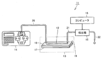
- FIG. 1 is a diagram schematically showing a configuration of an analyzer according to the present invention.
- an analyzer 11 separates each component of a mixed sample through a chromatography column using the principle of chromatography for a mixed sample in which a plurality of types of components are mixed, Each separated component is detected and analyzed.
- Such an analyzer 11 is used for, for example, analysis of each component in a mixed sample of biological fluid in which a plurality of types of proteins and the like are mixed.
- the analyzer 11 has a flow channel 12 that extends substantially straight in one direction and allows the mobile phase and the mixed sample to flow therein, and the components of the mixed sample including a plurality of types of components that are moved by the mobile phase.
- the chromatographic column 13 to be separated, the pump 14 for introducing the mixed sample into the column 13 together with the mobile phase, the detector 15 for detecting each component of the sample separated by the column 13, the operation of the detector 15 and the like are controlled.
- the pump 14 is disposed on the upstream side of the flow path 12, and the pump 14 and the column 13 are connected by a pipe 20.
- the pump 14 introduces the mobile phase and the mixed sample from the upstream side which is one end of the flow path 12 in the column 13 through the pipe 20.
- the detector 15 is disposed on the downstream side of the flow path 12, and the detector 15 and the column 13 are connected by a pipe 21.
- the mixed sample is separated into each component by the column 13, discharged from the downstream side which is the other end of the column 13, and introduced into the detector 15 through the pipe 21.
- the detector 15 detects each introduced component, that is, what kind of component each component is.
- the detector 15 is also provided with a pipe 22 for discharging the mobile phase containing each detected component out of the detector 15 and then out of the analyzer 11. Note that the flow rate and flow rate of the mobile phase are appropriately selected depending on the required performance of the column 13, the resolution, the type of components contained in the mixed sample, the amount of the mixed sample, and the like.
- the column 13 includes a substantially flat base portion 17 and a substantially flat cover portion 18 that covers the entire base portion 17.
- the flow path 12 described above is provided so as to be recessed from the surface 19 on one side of the substantially flat base portion 17.
- the channel 12 is configured to allow the mobile phase and the mixed sample to flow from the left side to the right side in FIG. That is, the left side of the channel 12 in FIG. 1 is the upstream side, and the right side of the channel 12 in FIG. 1 is the downstream side.
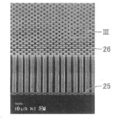
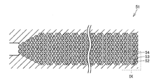
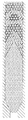
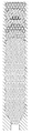
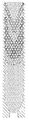
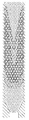
- FIG. 2 is an enlarged photograph showing a part of the appearance of the column 13 according to the present invention.
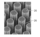
- FIG. 3 is an enlarged photograph of a portion indicated by III in FIG.
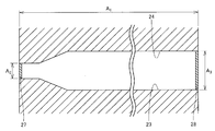
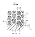
- FIG. 4 is a schematic cross-sectional view showing the outer shape of the column 13 according to the present invention.
- FIG. 4 is a cross-sectional view of the column 13 cut along a plane orthogonal to the direction in which the column portion 26 extends.
- the flow path 12 includes a pair of opposing side walls 23, 24 and a bottom wall 25 disposed on the bottom side of the pair of side walls 23, 24.
- the shape of the side walls 23, 24 is illustrated so as to extend straight in the left-right direction, but to be precise, the shape of the side walls 23, 24 is shown in FIGS. As shown in The specific shapes of the side walls 23 and 24 will be described later.
- a plurality of column portions 26 extending in a cylindrical shape from the bottom wall 25 constituting the flow path 12 are provided.
- the column portion 26 is provided so as to extend straight from the bottom wall 25 in the upward direction, that is, in the upward direction in the drawing of FIG.
- the tip of the columnar column portion 26 is configured to abut on the lower surface of the cover portion 18 when the cover portion 18 is disposed on the base portion 17. That is, when the cover portion 18 is disposed on the base portion 17, the cover portion 18 is located between the plurality of column portions 26 in a space surrounded by the pair of side walls 23, 24, the bottom wall 25, and the cover portion 18.
- the region becomes a flow path 12 that moves the mobile phase and the mixed sample to flow.
- the surface of the column part 26, that is, the outer surface of the column part 26 is formed of a curved surface, and is configured so as to be capable of so-called chemical modification.
- the plurality of column portions 26 serve as stationary phases in chromatography. A specific arrangement configuration of the plurality of column parts 26 will be described later.
- Both side walls 23 and 24 have a shape extending upward along the direction in which the column part 26 extends.
- the size of the inlet 27 into which the mobile phase and the mixed sample are introduced specifically the vertical width of the inlet 27 in FIG.
- the outlet 28 is configured to be smaller than the vertical width of the outlet 28 from which the sample separated into the components is discharged.
- the side walls 23 and 24 are configured to extend straight from the inlet 27 in the moving direction, and then extend in a tapered shape so as to increase their width.
- the column 13 has such a scale, that is, a micrometer order. As can be understood from FIG. 4 and the like, the column 13 has a shape that is long in the horizontal direction, that is, in the horizontal direction.
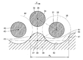
- FIG. 5 is a schematic sectional view showing a part of the column 13 according to the present invention.
- FIG. 6 is an enlarged view of a portion indicated by VI in FIG.
- FIG. 7 is an enlarged view of a portion indicated by VII in FIG. 5 to 7 correspond to cross sections in which the column 13 is cut along a plane orthogonal to the direction in which the column portion 26 extends.
- the length direction means the column length direction represented by the left-right direction of the paper surface in FIGS. 5-7
- the width direction means the vertical direction of the paper surface in FIGS. Indicates the width direction of the represented column.
- the moving direction of the mobile phase and the mixed sample is indicated by an arrow V in FIGS.
- the columnar column portion 26 has a circular outline.
- the plurality of pillars 26 are regularly arranged at predetermined intervals so that the coordinates of the centers of the pillars 26 are arranged in the close-packed structure. That is, in each pillar part 26, the shortest distance with the adjacent pillar part 26 is an equal structure, respectively.
- a first row 29 provided with seven column portions 26 arranged in the width direction and a second row 30 provided with six column portions 26 arranged in the width direction are arranged in the length direction. It is the structure arranged alternately. And in the cross section shown in FIG. 5 etc.
- the shape which tied each center of three pillar parts 26 with a straight line is as follows. It becomes an equilateral triangle.
- the shortest distance A 4 between the pillar portion 26 shown in FIG. 6 is a predetermined distance as described above, is set to 2 [mu] m.
- the region where the mobile phase and the mixed sample move between the column portions 26 becomes the central region, and the region where the mobile phase and the mixed sample move between the column portion 26 and the side walls 23 and 24 becomes the end region. .
- the pillar 26 located closest to the side wall 23 in the first row 29 is defined as the first pillar 31, and in the second row 30.
- the column portion 26 closest to the side wall 23 is defined as a second column portion 32.
- the first and second column parts 31 and 32 are adjacent to each other in the moving direction. In the width direction, the first column part 31 is outside the second column part 32, that is, the flow direction. It is provided at a position far from the center in the width direction of the path 12.
- a virtual circle in contact with the outline 34 of the second column 32 is drawn around the center 33 of the first column 31.
- a virtual circle outline 35 is indicated by a dotted line.
- the center 37 has a center 37 such that a line connecting the center and the respective centers 33 and 36 of the first and second column parts 31 and 32 becomes an equilateral triangle.
- the virtual pillar part 38 which is the same is drawn.
- the outline 39 of the imaginary column 38 is indicated by a one-dot chain line.
- equilateral triangles created by connecting the centers 33, 36, and 37 are also indicated by alternate long and short dash lines.
- the virtual pillar part 38 will be the pillar part formed in the flow path in the arrangement pattern in the close-packed structure. Note that both of the outlines 35 and 39 have an arc shape.
- the side wall 23 is a part of the drawn outline 35 of the virtual circle and a part of the drawn outline 39 of the virtual column part 38 in the above-described cross section, that is, for example, the cross section shown in FIG. Is a shape obtained by repeating an uneven shape composed of lines connected in the flow direction of the mobile phase.
- a line constituting the side wall 23 is indicated by a thick solid line 40 in FIG.
- a region close to the second pillar portion 32 specifically, from the intersection 41 of the virtual circle outline 35 and the virtual pillar 38 outline 39.
- a third column portion 42 that is further adjacent to the second column portion 32 in the moving direction, an outline of a virtual circle that touches the outline 34 of the second column portion 32 around the center 43 of the third column portion 42.
- the line constituting the side wall 23 becomes the outer shape line 39 of the virtual pillar portion 38.
- the side wall 23 becomes a curved surface along the outer shape surface of the column portion 31.
- the line constituting the side wall 23 is a line along the virtual circular outline 35.
- the line constituting the side wall 23 is a line along the virtual circle outline 44.
- a shape in which irregularities are repeated with respect to the reference line 46 that is, the center side of the flow path 12, in this case, a portion protruding from the reference line 46 toward the upper side of the paper surface in FIG.
- the portions that are recessed from the reference line 46 in the downward direction of the drawing in FIG. 7 are shapes that appear alternately and repeatedly in the length direction.
- the region in the length direction from the intersection point 47 to the intersection point 45 with the outline line (not shown) of the virtual column part drawn in the same manner as the drawn outline line 35 of the virtual circle the unit of the sidewall shape is a 5 is repeated, the sidewall shape formed in this area, a shape that repeats according to the number of the plurality of pillar portions 26 provided.
- the second pillar portion 32 and the side wall 23 shown at the shortest distance and the length dimension A 7, the first pillar portion 31 and the side wall 23 shown by the length dimension A 6 in FIG. 6 The shortest distance is 2 ⁇ m. Note that the tapered region of the side wall 23 is also configured in the same shape as shown in FIG.
- the shape of the other side wall 24 is also the same as the shape of the one side wall 23 described above, and a description thereof will be omitted.
- the column 13 having such a configuration the interval between the column portions 26 adjacent to each other in the central region in the flow channel 12 and the interval between the column portions 31 and 32 and the side wall 23 in the region close to the side wall 23 in the flow channel 12 are obtained. And in the moving direction of the moving layer flowing in the flow path 12, the difference between the moving speed in the central region and the moving speed in the end region close to the side wall 23 can be reduced. That is, the difference in moving speed in each region can be reduced.
- the outer surface of the column part 26 includes a curved surface
- the side wall 23 includes a curved surface along the outer surface of the column part 26 as a part thereof, so that the flow of the mobile phase in the region close to the side wall 23 is smooth. Can be. Therefore, the column 13 having such a configuration can improve the resolution by reducing the influence of flow path diffusion or the like when the mixed sample is separated into each component.
- the side wall 23 can be formed continuously with a line constituting an arc, and the movement of the mobile phase in the end region can be efficiently suppressed, so that the mobile phase moves smoothly in the flow path. Is possible.
- a substantially flat base portion made of silicon (Si) or the like is prepared.
- masking is performed on the part that will become the pillar part and the part that will become the side wall later on the main surface that becomes one surface in the plate thickness direction of the base part. That is, masking is performed on regions corresponding to the external shapes of the plurality of pillars and side walls.
- a photolithography technique used in manufacturing a semiconductor element or the like may be applied.
- the etching process is performed so that the masked area remains by etching and the other area is cut down to the portion corresponding to the bottom wall. That is, the non-etched member that has been masked is etched to form flow paths between the plurality of column portions and between the column portions and the pair of side walls.
- the flow path according to the present invention is formed, and the column is manufactured.
- a high resolution column for chromatography can be produced accurately and efficiently.
- the fine structure of the column specifically, the shape of the column part and the side wall described above is reproduced more faithfully and accurately, it can be performed accurately and efficiently. it can.
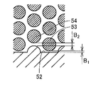
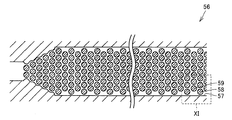
- FIG. 8 is a diagram showing a configuration of a conventional first column flow path.
- FIG. 9 is an enlarged view of a portion indicated by IX in FIG. 8 corresponds to FIG. 5, and FIG. 9 corresponds to FIG. 8 and FIG. 9 show FIG. It is a model of a channel indicated by (b).
- the conventional first column 51 has a configuration in which a semi-cylindrical column portion obtained by cutting the column portion in half is provided at a position where the side wall 52 is provided. Pillar portion 53 and the width direction of the length dimension B 1 is the shortest distance between the side walls 52 corresponding to the first pillar portion shown in FIG.
- the second pillar portion shown in FIG. 9 appropriate column portion 54 and the width direction is the shortest distance between the side wall 52 the length dimension B 2 is 2 [mu] m.
- the shortest distance between pillar parts is 2 micrometers.
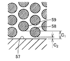
- FIG. 10 is a diagram showing the configuration of the flow path of the conventional second column.
- FIG. 11 is an enlarged view of a portion indicated by XI in FIG. 10 corresponds to FIG. 5, and FIG. 11 corresponds to FIG. 10 and FIG. 11 show FIG. It is a model of a channel indicated by (c).
- the conventional second column 56 has a configuration in which the side wall 57 is connected straight in the length direction. Pillar portion 58 and the width direction of the length dimension C 1 is the shortest distance between the side walls 57 corresponding to the first pillar portion shown in FIG. 11 is 1 [mu] m, the second pillar portion shown in FIG. 11 corresponding pillar portions 59 in the width direction of the length dimension C 2 is the shortest distance between the side wall 57 is 4 [mu] m. In addition, the shortest distance between pillar parts is 2 micrometers.
- the structure of the flow path 12 of the column 13 according to the present invention is as shown in FIGS. 5 to 7, and the length dimension in the width direction between the first column portion 31 and the side wall 23 and the second column. Both the length dimension of the width direction of the part 32 and the side wall 23 is 2 micrometers. The shortest distance between the column portions 26 is also 2 ⁇ m.
- FIG. 12 is an analysis diagram showing a distribution state of the mixed sample in the flow direction after a predetermined time has elapsed in the conventional first column 51.
- FIG. 13 is an analysis diagram showing a distribution state in the flow direction of the mixed sample after a predetermined time has elapsed in the conventional second column 56.
- FIG. 14 is an analysis diagram showing the distribution state of the mixed sample in the flow direction after a predetermined time has elapsed in the column 13 according to the present invention.
- the input conditions for the analysis are as follows: the diameter of the column is 5 ⁇ m, the flow rate is 52266 ⁇ m 3 / sec, the diffusion coefficient is 500 ⁇ m 2 / sec, the concentration of the solution is 20 ⁇ M (Mol), and the Courant number (C) is 0.
- the Courant number is an index that determines the time increment at the time of analysis, and is also an index that indicates the stability of the analysis result. Note that. Usually, it is said that the reliability of the analysis result is improved by performing the analysis with C ⁇ 1.
- FIG. 15 is an analysis diagram showing the distribution state of the mixed sample in the flow direction after a predetermined time has elapsed in a column in which the interval between the column portions is 2 ⁇ m and the interval between the column portions and the side walls is 1 ⁇ m.
- FIG. 16 is an analysis diagram showing a distribution state of the mixed sample in the flow direction after a predetermined time has elapsed in a column in which the interval between the column portions is 2 ⁇ m and the interval between the column portions and the side walls is 3 ⁇ m.
- FIG. 17 is an analysis diagram showing a distribution state of the mixed sample in the flow direction after a predetermined time has elapsed in a column in which the interval between the column portions is 2 ⁇ m and the interval between the column portions and the side walls is 4 ⁇ m.
- the same components of the mixed sample are indicated by the same hatching, but the boundary is not clear and is illustrated as a solid line from the viewpoint of easy understanding. is there.
- the moving speed in the end region that is, in the area close to the side wall, is larger than the moving speed in the central area in the width direction. It can be understood that it is also late. That is, in the conventional first and second columns 51 and 56, the distribution in the moving direction of the same component is moved in a large substantially V shape. Further, according to the analysis result shown in FIG. 15, the distribution in the moving direction of the same component moves in a large substantially V shape as in the case of FIGS. 12 and 13. According to the analysis results shown in FIG. 16 and FIG.
- the moving speed in the end region and the moving speed in the center region are almost the same, and the width in the moving direction of the same component is narrow. That is, in the column 13 according to the present invention, it can be understood that the moving speed in the end region and the moving speed in the central region are almost equal, and the speed difference is extremely small.
- the theoretical plate height is considered.
- the bandwidth is calculated from the position in the flow direction of the component moving fastest and the position in the flow direction of the component moving latest among the separated components. Further, since the bandwidth calculated in this way is normally calculated as 4 ⁇ , the calculated bandwidth is used as the value of 4 ⁇ in the calculation of the theoretical plate height.
- the bandwidth (4 ⁇ ) is indicated by the length dimension D in FIG.
- Table 1 shows the value of the theoretical plate height in each column. Incidentally, hitting the calculation, the column length is the length value of the dimension A 1 in FIG. 4, specifically, by using the value of 295Myuemu.
- the theoretical plate height of the conventional first column 51 is 4.49 ⁇ m
- the theoretical plate height of the conventional second column 56 is 2.52 ⁇ m.
- the theoretical plate height of the column 13 according to the present invention is 1.75 ⁇ m, which is significantly smaller than the theoretical plate height values of the first and second columns 51 and 56 in the related art. . Also from such a result, it is possible to grasp the high resolution of the column 13 according to the present invention.
- FIG. 18 is a graph showing the analysis results when the concentration is detected by a detector in each column analyzed in FIGS. 12 to 14 described above.
- the horizontal axis indicates elapsed time (seconds), and the vertical axis indicates density change (duM / dt).
- the elapsed time indicates the elapsed time from the start of measurement, that is, the time when the mixed sample is introduced into the inlet.
- the concentration change appears after about 0.125 seconds, and the concentration change continues after about 0.17 seconds.
- the peak of concentration change is higher in the column according to the present invention than in the conventional first and second columns. That is, the column according to the present invention has a sharper distribution of concentration change than the conventional first and second columns. From these results, the resolution of the column according to the present invention is also improved. You can grasp the height.
- the resolution can be improved.
- the interval between the column portions and the interval between the column portions and the side walls are set to 2 ⁇ m.
- the present invention is not limited to this, and the interval between the column portions and the interval between the column portions and the side walls are required. It is arbitrarily determined according to the performance of the column to be used and the kind of each component of the mixed sample.
- the distance between the column parts and the distance between the column part and the side wall be 2 ⁇ m or less. In this way, higher resolution can be realized.
- FIG. 19 shows the analysis result when the interval between the column portions and the interval between the column portions and the side walls is 1 ⁇ m
- FIG. 20 shows the case where the interval between the column portions and the interval between the column portions and the side wall is 3 ⁇ m
- FIG. 21 shows the analysis result when the interval between the column portions and the interval between the column portions and the side walls is 4 ⁇ m.
- the analysis input conditions are the same as those shown in FIG. Referring to FIG. 19 to FIG. 21 and FIG. 14, in the input conditions for the analysis described above, the band width tends to increase if the interval between the column portions and the interval between the column portions and the side walls are increased. Therefore, for a model close to the input conditions of the analysis described above, the mixed sample can be separated with high resolution if the interval between the column portions and the interval between the column portions and the side walls are 2 ⁇ m or less.
- the flow path provided in the column has a shape that extends straight in the left-right direction, but is not limited thereto, and may be, for example, a shape that is folded back into a substantially U shape.
- the meandering shape may be such that the flow path is folded several times.
- the number of channel folds is set so that the moving speed on the one side wall and the moving speed on the other side wall are equal at the outlet position. The number is preferably the same number.
- the column portion is cylindrical.
- the shape of the column portion is not limited to this, and the shape of the column portion only needs to include a curved surface.
- an elliptical shape having a longitudinal direction in the length direction and an elliptical shape having a longitudinal direction in the width direction may be provided. Note that the number of column portions and the like can be arbitrarily selected according to the required column performance and the like.
- FIG. 22 is a schematic cross-sectional view showing a part of the flow path in the column, in which the column portion has an elliptical cross section that is long in the width direction, here, in the vertical direction of the drawing. Note that the cross section shown in FIG. 22 corresponds to the cross section shown in FIG.
- first and second column portions 62, 63 provided in a column 61 according to another embodiment of the present invention are column portions 62 on a plane orthogonal to the extending direction of the column portions 62, 63. , 63 has a cross-sectional elliptical shape that is long in the width direction.
- the column parts 62 and 63 are so-called elliptic cylinders. And it is provided so that the coordinate of the centers 64 and 65 of each pillar part 62 and 63 may become arrangement
- the side wall 66 has an outline of the second column portion 63 adjacent to the first column portion 62 with the center 64 of the first column portion 62 provided closest to the sidewall 66 as the center.
- a part of a virtual ellipse outline 69 similar to the ellipse constituted by the outline 68 of the column part 62 and its arc are the same as the arc constituting the column 62
- its center 70 Is an imaginary column part 71 that is positioned such that an isosceles triangle indicated by a one-dot chain line in FIG. 22 is formed when connecting the centers 64 and 65 of the first and second column parts 62 and 63, respectively.
- This is a shape in which a concave / convex shape formed by connecting a part of the outer shape line 72 is repeated in the flow direction of the mobile phase. Such a shape may be used.
- the line segment corresponding to the base is a line segment connecting the center 65 and the center 70.
- the column part may have an elliptical cross section that is long in the flow direction, that is, the moving direction that is the left-right direction on the paper surface.
- FIG. 23 is a cross-sectional view showing a part of the flow path of the column in this case.
- a column 76 according to still another embodiment of the present invention has the same configuration as the column shown in FIG. 22 except that the shape of the ellipse is long in the moving direction. Description is omitted. Such a shape may be used.
- the width on the inlet side is reduced and the width on the outlet side is increased.
- the present invention is not limited to this, for example, the width on the inlet side and the width on the outlet side. May be configured to be equal.
- the column having the above-described configuration is manufactured using etching in the manufacturing technique of the semiconductor element.
- the present invention is not limited thereto, and for example, for a flat base portion, The regions corresponding to the positions of the pillars and the side walls arranged as described above may be manufactured by being deposited by CVD (Chemical Vapor Deposition) or the like and extending from the bottom wall of the flow path.
- the column having the above-described configuration may be manufactured in a microfabrication in which a space between pillar portions is cut without applying a semiconductor element manufacturing technique.
- 11 analyzer 12 flow path, 13, 51, 56, 61, 76 column, 14 pump, 15 detector, 16 computer, 17 base part, 18 cover part, 19 side, 20, 21, 22 pipe, 23, 24 , 52, 57, 66 Side wall, 25 Bottom wall, 26, 31, 32, 38, 42, 53, 54, 58, 59, 62, 63, 71 Column, 27 Inlet, 28 Outlet, 29, 30 Row, 33 36, 37, 43, 64, 65, 70 center, 34, 35, 39, 44, 67, 68, 69, 72 outline, 40 solid line, 41, 45, 47 intersection, 46 reference line.
Landscapes
- Chemical & Material Sciences (AREA)
- Health & Medical Sciences (AREA)
- Analytical Chemistry (AREA)
- Physics & Mathematics (AREA)
- General Health & Medical Sciences (AREA)
- Clinical Laboratory Science (AREA)
- Life Sciences & Earth Sciences (AREA)
- Hematology (AREA)
- Fluid Mechanics (AREA)
- Chemical Kinetics & Catalysis (AREA)
- Engineering & Computer Science (AREA)
- Nanotechnology (AREA)
- Dispersion Chemistry (AREA)
- Biochemistry (AREA)
- General Physics & Mathematics (AREA)
- Immunology (AREA)
- Pathology (AREA)
- Treatment Of Liquids With Adsorbents In General (AREA)
- Automatic Analysis And Handling Materials Therefor (AREA)
Priority Applications (3)
| Application Number | Priority Date | Filing Date | Title |
|---|---|---|---|
| CN2010800647168A CN102812354A (zh) | 2010-02-25 | 2010-12-24 | 色谱分析柱及其制造方法、以及分析装置 |
| EP10846653.3A EP2541245A4 (en) | 2010-02-25 | 2010-12-24 | CHROMATOGRAPHY COLUMN, PROCESS FOR OBTAINING COLUMN AND ANALYSIS DEVICE |
| US13/581,418 US20120318049A1 (en) | 2010-02-25 | 2010-12-24 | Column for chromatography, method for producing same, and analysis device |
Applications Claiming Priority (2)
| Application Number | Priority Date | Filing Date | Title |
|---|---|---|---|
| JP2010-040077 | 2010-02-25 | ||
| JP2010040077A JP2011174856A (ja) | 2010-02-25 | 2010-02-25 | クロマトグラフィー用カラム、その製造方法、および分析装置 |
Publications (1)
| Publication Number | Publication Date |
|---|---|
| WO2011104990A1 true WO2011104990A1 (ja) | 2011-09-01 |
Family
ID=44506425
Family Applications (1)
| Application Number | Title | Priority Date | Filing Date |
|---|---|---|---|
| PCT/JP2010/073369 Ceased WO2011104990A1 (ja) | 2010-02-25 | 2010-12-24 | クロマトグラフィー用カラム、その製造方法、および分析装置 |
Country Status (6)
| Country | Link |
|---|---|
| US (1) | US20120318049A1 (enExample) |
| EP (1) | EP2541245A4 (enExample) |
| JP (1) | JP2011174856A (enExample) |
| CN (1) | CN102812354A (enExample) |
| TW (1) | TWI421493B (enExample) |
| WO (1) | WO2011104990A1 (enExample) |
Cited By (1)
| Publication number | Priority date | Publication date | Assignee | Title |
|---|---|---|---|---|
| CN108333283A (zh) * | 2017-01-20 | 2018-07-27 | 中国科学院上海微系统与信息技术研究所 | 一种含有流线型椭圆微柱阵列的微色谱柱及其制备方法 |
Families Citing this family (5)
| Publication number | Priority date | Publication date | Assignee | Title |
|---|---|---|---|---|
| BE1022314B1 (nl) * | 2013-02-05 | 2016-03-15 | PharmaFluidics N.V. | Chemische reactor inrichting |
| US10073068B2 (en) | 2013-09-18 | 2018-09-11 | Agilent Technologies, Inc. | Liquid chromatography columns with structured walls |
| BE1024344B1 (nl) * | 2016-07-04 | 2018-02-02 | PharmaFluidics N.V. | Productie van chemische reactoren |
| BE1026910B1 (nl) * | 2018-12-21 | 2020-07-22 | Pharmafluidics N V | Chemische reactoren |
| BE1028976B1 (nl) * | 2020-12-30 | 2022-08-01 | Pharmafluidics N V | Pilaarstructuren |
Citations (4)
| Publication number | Priority date | Publication date | Assignee | Title |
|---|---|---|---|---|
| WO2004051231A1 (ja) * | 2002-11-29 | 2004-06-17 | Nec Corporation | 分離装置および分離方法 |
| WO2008020593A1 (en) * | 2006-08-14 | 2008-02-21 | Tokyo Electron Limited | Column for chromatography and method for producing the same |
| WO2009028238A1 (ja) * | 2007-08-24 | 2009-03-05 | Tokyo Electron Limited | クロマト検出装置 |
| WO2009128294A1 (ja) * | 2008-04-19 | 2009-10-22 | ブラザー工業株式会社 | 検査対象受体及び当該検査対象受体を備えた検査装置 |
Family Cites Families (4)
| Publication number | Priority date | Publication date | Assignee | Title |
|---|---|---|---|---|
| JPH07120450A (ja) * | 1993-10-22 | 1995-05-12 | Sumika Bunseki Center:Kk | 多孔質体クロマトグラフィー用カラム |
| US6156273A (en) * | 1997-05-27 | 2000-12-05 | Purdue Research Corporation | Separation columns and methods for manufacturing the improved separation columns |
| JP2002301367A (ja) * | 2001-04-05 | 2002-10-15 | Gl Sciences Inc | クロマトグラフィー用多孔質体の製造方法 |
| CN101585507B (zh) * | 2009-06-23 | 2013-07-03 | 中国科学院上海微系统与信息技术研究所 | 一种pdms微流控芯片中通孔结构的制作方法 |
-
2010
- 2010-02-25 JP JP2010040077A patent/JP2011174856A/ja active Pending
- 2010-12-24 CN CN2010800647168A patent/CN102812354A/zh active Pending
- 2010-12-24 WO PCT/JP2010/073369 patent/WO2011104990A1/ja not_active Ceased
- 2010-12-24 EP EP10846653.3A patent/EP2541245A4/en not_active Withdrawn
- 2010-12-24 US US13/581,418 patent/US20120318049A1/en not_active Abandoned
-
2011
- 2011-02-23 TW TW100106052A patent/TWI421493B/zh not_active IP Right Cessation
Patent Citations (4)
| Publication number | Priority date | Publication date | Assignee | Title |
|---|---|---|---|---|
| WO2004051231A1 (ja) * | 2002-11-29 | 2004-06-17 | Nec Corporation | 分離装置および分離方法 |
| WO2008020593A1 (en) * | 2006-08-14 | 2008-02-21 | Tokyo Electron Limited | Column for chromatography and method for producing the same |
| WO2009028238A1 (ja) * | 2007-08-24 | 2009-03-05 | Tokyo Electron Limited | クロマト検出装置 |
| WO2009128294A1 (ja) * | 2008-04-19 | 2009-10-22 | ブラザー工業株式会社 | 検査対象受体及び当該検査対象受体を備えた検査装置 |
Non-Patent Citations (4)
| Title |
|---|
| ANALYTICAL CHEMISTRY, vol. 76, no. 15, 1 August 2004 (2004-08-01) |
| M.DE PRA ET AL.: "Experimental Study on Band Dispersion in Channels Structured with Micropillars", ANALYTICAL CHEMISTRY, vol. 78, no. 18, 15 September 2006 (2006-09-15), pages 6519 - 6525, XP002496764, DOI: doi:10.1021/ac060915h * |
| NICO VERVOORT ET AL.: "Importance and Reduction of the Sidewall-Induced Banb- Broadening Effect in Pressure-Driven Microfabricated", ANALYTICAL CHEMISTRY, vol. 76, no. 15, 1 August 2004 (2004-08-01), pages 4501 - 4507, XP002716069 * |
| See also references of EP2541245A4 |
Cited By (1)
| Publication number | Priority date | Publication date | Assignee | Title |
|---|---|---|---|---|
| CN108333283A (zh) * | 2017-01-20 | 2018-07-27 | 中国科学院上海微系统与信息技术研究所 | 一种含有流线型椭圆微柱阵列的微色谱柱及其制备方法 |
Also Published As
| Publication number | Publication date |
|---|---|
| JP2011174856A (ja) | 2011-09-08 |
| TW201142281A (en) | 2011-12-01 |
| US20120318049A1 (en) | 2012-12-20 |
| TWI421493B (zh) | 2014-01-01 |
| CN102812354A (zh) | 2012-12-05 |
| EP2541245A4 (en) | 2013-12-18 |
| EP2541245A1 (en) | 2013-01-02 |
Similar Documents
| Publication | Publication Date | Title |
|---|---|---|
| WO2011104990A1 (ja) | クロマトグラフィー用カラム、その製造方法、および分析装置 | |
| WO2008020593A1 (en) | Column for chromatography and method for producing the same | |
| EP2953716B1 (en) | Chemical reactor device | |
| JP6509330B2 (ja) | 微細構造分離フィルタ | |
| Vangelooven et al. | Design and evaluation of flow distributors for microfabricated pillar array columns | |
| CN112816608B (zh) | 微色谱柱及制备方法 | |
| KR101584083B1 (ko) | 미소입자의 변형성 및 피로 특성 분석 장치 | |
| US12215023B2 (en) | Microfluidic devices and associated methods | |
| CN206460008U (zh) | 一种含有流线型椭圆微柱阵列的微色谱柱 | |
| CN108333283B (zh) | 一种含有流线型椭圆微柱阵列的微色谱柱及其制备方法 | |
| CN115060842A (zh) | 一种含有交错排列椭圆微柱阵列的微色谱柱及其制备方法 | |
| Palumbo et al. | Lab on a rod: Size-based particle separation and sorting in a helical channel | |
| CN114965833A (zh) | 一种微沟道横截面为圆角矩形的玻璃基微色谱柱 | |
| BE1027013B1 (nl) | Filter voor chemische reactoren | |
| US12011701B2 (en) | Chemical reactors | |
| US20240157361A1 (en) | Microfluidic device | |
| JP4661125B2 (ja) | 成分分離素子およびその製造方法 | |
| CN120539332A (zh) | 一种水滴状色谱柱及其制备方法 |
Legal Events
| Date | Code | Title | Description |
|---|---|---|---|
| WWE | Wipo information: entry into national phase |
Ref document number: 201080064716.8 Country of ref document: CN |
|
| 121 | Ep: the epo has been informed by wipo that ep was designated in this application |
Ref document number: 10846653 Country of ref document: EP Kind code of ref document: A1 |
|
| NENP | Non-entry into the national phase |
Ref country code: DE |
|
| WWE | Wipo information: entry into national phase |
Ref document number: 13581418 Country of ref document: US Ref document number: 2010846653 Country of ref document: EP |