WO2011102521A1 - 無線通信システム、通信装置、プログラムおよび集積回路 - Google Patents
無線通信システム、通信装置、プログラムおよび集積回路 Download PDFInfo
- Publication number
- WO2011102521A1 WO2011102521A1 PCT/JP2011/053771 JP2011053771W WO2011102521A1 WO 2011102521 A1 WO2011102521 A1 WO 2011102521A1 JP 2011053771 W JP2011053771 W JP 2011053771W WO 2011102521 A1 WO2011102521 A1 WO 2011102521A1
- Authority
- WO
- WIPO (PCT)
- Prior art keywords
- communication device
- unit
- turbo
- communication
- constraint length
- Prior art date
Links
Images


Classifications
-
- H—ELECTRICITY
- H04—ELECTRIC COMMUNICATION TECHNIQUE
- H04L—TRANSMISSION OF DIGITAL INFORMATION, e.g. TELEGRAPHIC COMMUNICATION
- H04L1/00—Arrangements for detecting or preventing errors in the information received
- H04L1/004—Arrangements for detecting or preventing errors in the information received by using forward error control
- H04L1/0045—Arrangements at the receiver end
- H04L1/0047—Decoding adapted to other signal detection operation
- H04L1/005—Iterative decoding, including iteration between signal detection and decoding operation
-
- H—ELECTRICITY
- H03—ELECTRONIC CIRCUITRY
- H03M—CODING; DECODING; CODE CONVERSION IN GENERAL
- H03M13/00—Coding, decoding or code conversion, for error detection or error correction; Coding theory basic assumptions; Coding bounds; Error probability evaluation methods; Channel models; Simulation or testing of codes
- H03M13/29—Coding, decoding or code conversion, for error detection or error correction; Coding theory basic assumptions; Coding bounds; Error probability evaluation methods; Channel models; Simulation or testing of codes combining two or more codes or code structures, e.g. product codes, generalised product codes, concatenated codes, inner and outer codes
- H03M13/2957—Turbo codes and decoding
- H03M13/296—Particular turbo code structure
-
- H—ELECTRICITY
- H04—ELECTRIC COMMUNICATION TECHNIQUE
- H04L—TRANSMISSION OF DIGITAL INFORMATION, e.g. TELEGRAPHIC COMMUNICATION
- H04L1/00—Arrangements for detecting or preventing errors in the information received
- H04L1/0001—Systems modifying transmission characteristics according to link quality, e.g. power backoff
- H04L1/0023—Systems modifying transmission characteristics according to link quality, e.g. power backoff characterised by the signalling
- H04L1/0025—Transmission of mode-switching indication
-
- H—ELECTRICITY
- H04—ELECTRIC COMMUNICATION TECHNIQUE
- H04L—TRANSMISSION OF DIGITAL INFORMATION, e.g. TELEGRAPHIC COMMUNICATION
- H04L1/00—Arrangements for detecting or preventing errors in the information received
- H04L1/0001—Systems modifying transmission characteristics according to link quality, e.g. power backoff
- H04L1/0002—Systems modifying transmission characteristics according to link quality, e.g. power backoff by adapting the transmission rate
- H04L1/0003—Systems modifying transmission characteristics according to link quality, e.g. power backoff by adapting the transmission rate by switching between different modulation schemes
-
- H—ELECTRICITY
- H04—ELECTRIC COMMUNICATION TECHNIQUE
- H04L—TRANSMISSION OF DIGITAL INFORMATION, e.g. TELEGRAPHIC COMMUNICATION
- H04L1/00—Arrangements for detecting or preventing errors in the information received
- H04L1/0001—Systems modifying transmission characteristics according to link quality, e.g. power backoff
- H04L1/0009—Systems modifying transmission characteristics according to link quality, e.g. power backoff by adapting the channel coding
-
- H—ELECTRICITY
- H04—ELECTRIC COMMUNICATION TECHNIQUE
- H04L—TRANSMISSION OF DIGITAL INFORMATION, e.g. TELEGRAPHIC COMMUNICATION
- H04L1/00—Arrangements for detecting or preventing errors in the information received
- H04L1/004—Arrangements for detecting or preventing errors in the information received by using forward error control
- H04L1/0056—Systems characterized by the type of code used
- H04L1/0067—Rate matching
- H04L1/0068—Rate matching by puncturing
- H04L1/0069—Puncturing patterns
Definitions
- the present invention relates to a wireless communication system, a communication device, a program, and an integrated circuit.
- Error correction methods for correcting errors due to thermal noise in the receiver include convolutional codes such as non-systematic convolutional (NSC) codes and recursive systematic convolutional (RSC) codes, LDPC ( Low Density Parity Check) code, turbo code in which RSC codes are connected in parallel (see Non-Patent Document 1), and the like.
- NSC non-systematic convolutional
- RSC recursive systematic convolutional
- LDPC Low Density Parity Check
- an encoder that generates an RSC code that is a component encoder is connected in parallel via an interleaver to perform turbo encoding in a transmitter encoding unit.
- the decoder of the receiver can achieve characteristics close to the Shannon limit by performing turbo decoding that performs iterative decoding.
- the turbo code is a coding method in which a plurality of RSC encoders are used in an encoder and an interleaver is applied to information bits to be encoded, so that each RSC encoder independently performs encoding.
- a frequency domain equalization processing method As a method for compensating for frequency selective fading, a frequency domain equalization processing method is generally used. For example, there is a method based on a minimum mean square error (MMSE) standard. Furthermore, improvement of reception characteristics by a turbo equalization technique (see Non-Patent Document 2) in which an iterative decoding method used in a turbo code is applied to an equalizer and a decoding unit is also being studied.
- MMSE minimum mean square error
- turbo equalization is a technique for detecting a signal by exchanging external information by iterative processing of a MAP (Maximum A Posteriori) detector and a decoder based on the turbo principle.
- the single-carrier MAP detector is a soft canceller that cancels replicas such as ISI fed back from a decoder, inter-user interference, inter-cell interference, and inter-antenna interference, and frequency domain equalization.
- the present invention can also be applied to multicarriers, and the MAP detector in that case is a soft canceller that cancels replicas such as intersymbol interference and intercarrier interference.
- the present invention provides a wireless communication system, a communication device, a program, and an integrated circuit that can further improve communication reliability in a communication system that uses a turbo code as an error correction code.
- a wireless communication system is a wireless communication system including a first communication device and a second communication device, and the second communication device receives a signal by turbo equalization.
- the first communication device includes a turbo coding unit that configures a plurality of component encoders having different constraint lengths with different constraint lengths.
- the first communication device when the first communication device transmits an information bit as a transmission signal to the second communication device, the first communication device performs error correction code.
- the turbo code unit having a plurality of component encoders for generating a plurality of error correction codes inserted into information bits, encoding the information bits with the error correction codes inserted therein, and generating the transmission signal Also good.
- the turbo code unit includes a communication parameter set by a propagation characteristic of a signal received by the second communication device from the first communication device, and the communication parameter. May be compared with a condition value that deteriorates the convergence of the iterative process in turbo equalization, and the plurality of component encoders may be configured with different constraint lengths depending on the comparison result.
- the constraint length of any one of a plurality of component encoders constituting the turbo code unit may be changed.
- the plurality of component encoders may be set to different constraint lengths.
- any one of the communication parameters corresponds to a condition value that deteriorates convergence of repetition processing in turbo equalization
- any one component in the turbo coding unit The constraint length of the encoder may be changed.
- the second communication device allows allocation of overlapping bands to the plurality of first communication devices, and the received transmission signal is turbo-equalized.
- the second communication device assigns a frequency band, a coding rate, and a modulation multilevel number of modulation symbols assigned to each of the plurality of first communication devices, and the second The communication parameter which determines the control information which consists of the number of receiving antennas used by the communication device, and which consists of the duplication rate of the band which the second communication device has assigned to the control information and the plurality of first communication devices in duplicate.
- the plurality of components encoders may be encoded using a turbo coding unit constituting a different constraint length.
- the second communication device determines a band to be assigned to each of the plurality of transmission antennas of the first communication device, and is overlapped with the plurality of transmission antennas.
- the second communication apparatus determines the frequency band allocated to each of the plurality of transmission antennas, the coding rate, and the modulation multi-level number of modulation symbols.
- Control information and the second communication apparatus determines all or part of the communication parameters including the control information, a duplication rate of bands allocated to a plurality of transmission antennas, and the number of reception antennas.
- the first communication device is notified, the communication parameter notified by the first communication device, and a condition value that deteriorates the convergence of the iterative process in turbo equalization.
- the plurality of components encoders may be encoded using a turbo coding unit constituting a different constraint length.
- the second communication device when the second communication device allows allocation of overlapping bands to the plurality of first communication devices and performs reception processing by turbo equalization processing, The second communication device determines control information including a band, a coding rate, and a modulation multi-level number allocated to each of the plurality of first communication devices, and the second communication device determines the control information and the plurality of first information.
- the constraint length for each component encoder of the turbo coding unit in the first communication device is determined by comparing with a condition value that deteriorates the convergence of the iterative processing in Notifies information to the first communication device, the first communication device, may be changed constraint length of the component encoder in the turbo coding unit.
- the second communication device determines a band to be assigned to each of the plurality of transmission antennas of the first communication device, and is a band that overlaps the plurality of transmission antennas.
- the second communication apparatus determines control information consisting of a band, a coding rate, and a modulation multi-value number assigned to each of a plurality of transmission antennas, All or part of the communication parameters including the overlapping rate of the control information and the band allocated to the plurality of transmitting antennas and the number of receiving antennas, and the convergence of the corresponding communication parameters and the iterative processing in turbo equalization
- the constraint length for each component encoder of the turbo coding unit in the first communication device is compared with a condition value that deteriorates the performance. Constant, and notifies the information of the constraint length to the first communication device, the first communication device, may be changed constraint length of the component encoder in the turbo coding unit.
- the first communication device transmits a spatially multiplexed signal to the second communication device using a plurality of transmission antennas, and the second communication device.
- the second communication apparatus assigns a band, a coding rate, and a modulation multi-value to each of the plurality of transmission antennas.
- Control information consisting of a number, a correlation value between the antennas calculated from the control information and propagation path estimation for each of a plurality of antennas, all or a part of the communication parameters consisting of the number of receiving antennas, and the corresponding
- the component of the turbo coding unit in the first communication device is compared.
- the constraint length for each encoder is determined, the constraint length information is notified to the first communication device, and the first communication device uses the constraint length information to determine the constraint length of the component encoder in the turbo encoder. You may change the length.
- the first communication device transmits a spatially multiplexed signal to the second communication device using a plurality of transmission antennas
- the second communication device When performing reception processing by separation and turbo equalization of a spatially multiplexed signal using a plurality of receiving antennas, a band and a coding rate, a modulation multi-level number, and the second communication apparatus allocate to each of the plurality of antennas, Control information consisting of an antenna correlation value calculated from propagation path estimation for each of the plurality of antennas and the number of receiving antennas is determined, and the control information is transmitted to the first communication device.
- the turbo code Determining the constraint length of each component encoder, the plurality of components encoders in the turbo coding unit may be a constraint length different.
- the constraint length of the component encoder of the coding unit may be changed.
- the second communication apparatus determines control information including a band to be assigned to each of a plurality of transmission antennas, a coding rate, and a modulation multi-level number, and the control information And all or part of the communication parameters consisting of the correlation value between the antennas calculated from the channel estimation for each of the plurality of antennas and the number of receiving antennas, and the convergence of the corresponding communication parameters and the iterative processing in turbo equalization.
- a constraint length for each component encoder of the turbo coding unit in the second communication device may be determined by comparing with a condition value to be deteriorated, and the information on the constraint length may be notified to the first communication device. .
- a communication device includes a turbo code unit having a plurality of component encoders, and each of the plurality of component encoders in the turbo code unit uses a different constraint length.
- the information bit when the information bit is transmitted as a transmission signal to another communication device, the information bit is transmitted by the turbo code unit having the plurality of component encoders that generate an error correction code.
- the transmission signal may be generated by inserting a plurality of the error correction codes into the information bits and encoding the information bits in which the error correction codes are inserted.
- any one of the communication parameters corresponds to a condition value that deteriorates convergence of repetition processing in turbo equalization
- any one component encoder in the turbo encoder The restraint length may be changed.
- Each of the plurality of component encoders may have a different constraint length.
- the other communication device determines a band to be assigned to each of the plurality of transmission antennas included in the communication device, and permits the allocation of overlapping bands to the plurality of transmission antennas.
- each of the plurality of component encoders in the turbo coding unit may have a different constraint length.
- the constraint length of the component encoder may be changed according to the comparison result by comparing with a condition value that deteriorates the convergence of the repetition process in turbo equalization in the communication apparatus.
- the constraint length of each of the two component encoders in the turbo encoder may be 3 and the other may be 4.
- communication parameters including band allocation information, modulation scheme, coding rate, band duplication ratio, correlation value between antennas, and number of receiving antennas from the other communication apparatuses. All or a part of the above may be notified, and based on the notified communication parameter information, the constraint length of the component encoder in the turbo encoder may be determined, and turbo encoding may be performed.
- a program according to an aspect of the present invention is a program that causes a computer to execute processing for controlling a communication device.
- the communication device A computer-executable program for configuring a plurality of component encoders having different constraint lengths with different constraint lengths.
- communication comprising band allocation information, modulation scheme, coding rate, band duplication rate, correlation value between antennas, and number of receiving antennas notified from the other communication device.
- the constraint length may be determined for each component encoder in the turbo encoder, and turbo encoding may be performed.
- control information including allocation information of a band to the other communication device, a modulation scheme, and a coding rate, a band duplication rate in the control information, and a correlation between antennas
- the value and the number of reception antennas of the communication device may be used as communication parameters, and the communication device may transmit information to the other communication device as information for determining a constraint length for each component encoder in the turbo coding unit. .
- control information including bandwidth allocation information, a modulation scheme, and a coding rate to the other communication device, a bandwidth duplication rate between the devices in the control information, an antenna
- the correlation value between the communication device and the number of reception antennas of the communication device is a communication parameter, and by using this communication parameter, a constraint length for each component encoder in the turbo coding unit in the other communication device is obtained, and the obtained constraint length is You may make it transmit with respect to another communication apparatus.
- An integrated circuit according to an aspect of the present invention is an integrated circuit of a communication device, and when another communication device performs signal reception processing by turbo equalization, the communication device has a plurality of constraint lengths different from each other. Configure component encoders with different constraint lengths.
- the communication device when the communication device transmits an information bit as a transmission signal to the other communication device, the other communication device generates an error correction code.
- a turbo code unit having an encoder inserts a plurality of error correction codes into information bits, encodes the information bits into which the error correction codes are inserted, generates the transmission signal, and generates a plurality of information in the turbo code unit.
- Each component encoder may use a different constraint length.
- the integrated circuit includes a plurality of component encoders that generate an error correction code when the other communication device transmits an information bit as a transmission signal to the communication device.
- a plurality of error correction codes inserted into information bits, encoding the information bits into which the error correction codes have been inserted, generating the transmission signal, and assigning a band to each of the plurality of transmission antennas.
- Control information consisting of coding rate and modulation multi-level number is determined, all the communication parameters consisting of the control information and the correlation value between antennas calculated from propagation path estimation for each of a plurality of antennas, the number of receiving antennas, or By comparing a part of the communication parameter with a condition value that deteriorates the convergence of turbo equalization, the other communication device That determines the constraint length of each component encoder of the turbo encoding unit, the information of the constraint length may be notified to the other communication device.
- a coding constraint length in a component encoder is changed to a coding rate, a modulation scheme, band allocation information, and band allocation overlap with other transmission apparatuses.
- FIG. 3 is a block diagram illustrating a configuration example of turbo encoding units 101 and 701.
- FIG. 3 is a block diagram illustrating a configuration example of an encoding unit 201 or 204.
- FIG. 12 is a block diagram illustrating another configuration example of the encoding unit 201 or 204.
- FIG. 1 is a conceptual diagram of a radio communication system according to the first embodiment of the present invention.
- a base station apparatus eNB performs radio communication with a plurality of terminal apparatuses UE1, UE2, and UE3 using downlinks and uplinks.
- Each of the base station device eNB and the plurality of terminal devices UE1, UE2, UE3 is a device having a function of a transceiver.
- a case will be described in which each of the terminal apparatuses UE1, UE2, UE3 transmits a data signal to the base station apparatus eNB through an uplink.
- the terminal device is referred to as a transmission device and the base station device eNB is referred to as a reception device in terms of the data signal transmission side and the reception side. Therefore, the transmitting device and the receiving device referred to here include a case where the former refers to the transmitting unit of the terminal device and the latter refers to the receiving unit of the base station device, but is not limited thereto.
- the terminal apparatus UE1 performs MIMO (Multiple Input Multiple Output) transmission using the same spatially multiplexed frequency using the two transmission antennas T1 and T2.
- the terminal apparatuses UE2 and UE3 perform data transmission using one transmission antenna.
- MIMO Multiple Input Multiple Output
- the number of antennas used for data transmission by each terminal apparatus UE1, UE2, UE3 is determined by the base station apparatus eNB by assigning the number of antennas and bandwidth used for transmission from the propagation path status, and each terminal apparatus UE1, UE2, UE3 To notify.
- the base station device eNB can allocate discrete bands to the terminal devices UE2 and UE3.
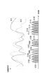
- FIG. 2 shows an example of allocation of discrete bands to the terminal device UE2 and the terminal device UE3.
- the horizontal axis indicates the frequency.
- the chevron figures C101, C107, C108, C113, C114, and C115 hatched with diagonally lowering lines and the chevron figures C102, C103, C111, and C112 hatched with diagonally lowering and diagonally lowering grid lines are users.
- the subcarrier allocated to terminal device UE2 which is a terminal is shown.
- the chevron figures C104, C105, C106, C109, and C110 hatched with slanting left-down lines and chevron figures C102, C103, C111, and C112 hatched with slanting right-down and slanting left-down grid lines are user terminals.
- the subcarrier allocated to a certain terminal device UE3 is shown. Therefore, the chevron figures C102, C103, C111, and C112 hatched with diagonally downward and diagonally downward grid lines are subcarriers allocated to both the terminal apparatuses UE2 and UE3, that is, subcarriers allocated to a plurality of terminal apparatuses. Indicates.
- the curve G11 shows a propagation path gain curve of the propagation path of the terminal device UE2.
- the curve G12 shows the propagation path gain curve of the propagation path of the terminal device UE3.
- allocation to each terminal device UE2 and UE3 is described as a subcarrier unit, but an integer multiple of subcarriers may be used as the minimum unit of allocation bandwidth. For example, 12 subcarriers may be used as resource blocks and allocation may be performed in resource block units.
- FIG. 2 shows the propagation path gain curves of the propagation paths of the terminal apparatuses UE2 and UE3 with the vertical axis as the propagation path gain. That is, the curve G11 shows a propagation path gain curve of the propagation path of the terminal device UE2. Moreover, the curve G12 shows the propagation path gain curve of the propagation path of the terminal device UE3.
- allocation to each terminal device UE2 and UE3 is described as a subcarrier unit, but an integer multiple of subcarriers may be used as the minimum unit
- FIG. 3 is a block diagram illustrating a configuration example of the terminal apparatuses UE2 and UE3 in the present embodiment. This embodiment demonstrates as a structure of the transmitter of terminal device UE2 and UE3.
- the terminal device UE2 includes a turbo encoding unit 101, a modulation unit 102, an FFT (Fast Fourier Transform) unit 103, a mapping unit 104, an IFFT (Inverse Fast Fourier Transform) unit 105, and a reference signal multiplexing unit. 106, an encoding method determination unit 107 and a control information reception unit 108.
- the terminal device UE3 has the same configuration as the terminal device UE2.
- the terminal device UE2 receives the control information D11 notified from the receiving device of the base station device eNB by the control information receiving unit 108.
- the control information received by the control information receiving unit 108 includes a coding rate, a modulation scheme, bandwidth allocation information, a bandwidth allocation overlap rate with other transmission apparatuses, and the like.
- the control information receiving unit 108 outputs information such as the coding rate, modulation scheme, and band duplication rate included in the control information to the coding method determining unit 107. Further, the control information receiving unit 108 outputs the modulation scheme included in the control information to the modulation unit 102. Further, the control information receiving unit 108 outputs the band allocation information to the mapping unit 104.
- the encoding method determination unit 107 selects one of a plurality of preset puncture patterns based on the notified encoding rate, and determines a puncture pattern to be used. Also, the encoding method determination unit 107 determines information related to the encoding constraint length based on the encoding rate, modulation scheme, and duplication rate. Then, the encoding method determination unit 107 outputs information regarding the determined puncture pattern and encoding constraint length to the turbo encoding unit 101. The encoding method determination unit 107 stores an encoding rate and a puncture pattern in association with each other.
- the constraint length indicates the number of bits to be convoluted in the convolutional code generated by the RSC encoder.
- the turbo encoding unit 101 encodes the data bit D12 of the terminal apparatus UE2 using the information regarding the encoding input from the encoding method determination unit 107, and outputs the encoded bit to the modulation unit 102.
- the modulation unit 102 controls the input coded bits from among modulation such as QPSK (Quaternary Phase Shift Keying) and 16QAM (16-ary Quadrature Amplitude Modulation).
- a modulation symbol received from the reception unit 108 is modulated to obtain a modulation symbol. Thereafter, modulation section 102 outputs this modulation symbol to FFT section 103.
- the number of bits constituting one modulation symbol is defined as a modulation multi-level number.
- QPSK is composed of 2 bits to 1 symbol
- 16QAM is composed of 4 bits.
- FFT section 103 converts the modulation symbol input from modulation section 102 from a time domain to a frequency domain data signal, and outputs the converted data signal to mapping section 104.
- Mapping section 104 performs processing for allocating frequency domain data signals to corresponding bands based on band allocation information input from control information receiving section 108, and outputs the allocated data signals to IFFT section 105.
- IFFT section 105 converts the frequency domain data signal into a time domain transmission signal and outputs the converted transmission signal to reference signal multiplexing section 106.
- the reference signal multiplexing unit 106 performs a process of multiplexing the reference signal D13 (a pilot signal whose code pattern is known) on the transmission signal in the time domain, and outputs it as the transmission signal D14 of the terminal apparatus UE2.
- the transmission signal D14 is converted into an analog signal by D / A (Digital / Analog) conversion after CP (Cyclic Prefix) is inserted, It is then upconverted to a radio frequency.
- the up-converted signal is amplified to transmission power by a PA (Power Amplifier) and then transmitted from the transmission antenna.
- the terminal device UE3 generates a transmission signal by signal processing similar to that of the terminal device UE2, up-converts it, amplifies it to transmission power by the power amplifier PA, and transmits it from the transmission antenna.
- the reference signal multiplexing unit 106 multiplexes the reference signal in the time domain, but the mapping unit 104 may multiplex the reference signal to the transmission signal in the frequency domain. In this case, the reference signal multiplexing unit 106 is not necessary.
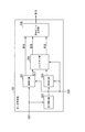
- the turbo encoding unit 101 includes an encoding unit 201, a puncturing unit 202, a rearrangement unit 203, an encoding unit 204, and an encoded bit output unit 205.
- Data D15 including puncture patterns and information on constraint lengths is input from the encoding method determination unit 107 to the turbo encoding unit 101.
- the constraint length information is transmitted to the coding unit 201 and the coding unit 204 in the turbo coding unit 101 based on the coding rate, duplication rate, and modulation scheme information. , And information on the obtained constraint length.
- the encoding unit 201 performs RSC (Recursive Systematic Convolutional) encoding of the notified constraint length for the data bit D12 (information bit), the systematic bit D16 that is the data bit itself, and the RSC code
- the parity bit D17 obtained by the conversion is output.
- encoding section 201 outputs systematic bit D16 to code bit output section 205, and also outputs parity bit D17 to puncturing section 202.
- Rearranger 203 rearranges (interleaves) the data bits by changing the bit order of the input data bits, and outputs the rearranged data bits to encoder 204.
- the encoding unit 204 performs RSC encoding on the rearranged data bits input from the rearrangement unit 203 based on the constraint length notified from the encoding method determination unit 107.
- the rearrangement pattern of the rearrangement unit 203 holds the same pattern in advance in the turbo coding unit 101 and the decoding unit in the base station apparatus eNB. For this reason, the encoding part 204 does not need to transmit a systematic bit. Therefore, encoding section 204 generates only parity bits and outputs them to puncturing section 202.
- Each of the encoding units 201 and 204 described above generates different parity bits to be added to the systematic bits that are information bits as error correction codes.
- the puncturing unit 202 includes the parity bit D17 output from the encoding unit 201 and the parity bit output from the encoding unit 204, and includes information related to the puncture pattern and the constraint length notified from the encoding method determination unit 107. Puncturing is performed using data D15. The same puncture pattern is preset in the turbo coding unit 101 of the terminal device UE2 and the decoding unit in the base station device eNB.
- the code bit output unit 205 connects the systematic bit D16 input from the encoding unit 201 and the punctured parity bit D18 input from the puncture unit 202.
- the turbo encoding unit 101 outputs a bit string in which the systematic bit D16 and the parity bit D18 output from the puncturing unit 202 are concatenated, as a code bit D19.
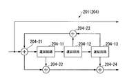
- FIGS. 5A and 5B are diagrams illustrating a configuration example of the encoding unit 201 or the encoding unit 204.
- the configuration of FIG. 5A is shown as an example of an encoding unit 201 (204) that performs RSC encoding with a constraint length of 4.
- the structure of FIG. 5B is shown as an example of the encoding part which performs RSC encoding with a constraint length of 3.
- the constraint length is a value obtained by adding 1 to the number of delay circuits.
- 5A includes delay circuits 204-11, 204-12, and 204-13, and adders 204-21, 204-22, 304-23, and 204-24.
- . 5B includes delay circuits 204-31 and 204-32 and adders 204-41, 204-42 and 204-43.
- Each of the encoding unit 201 and the encoding unit 204 corresponds to the constraint length input from the encoding method determination unit 107 (FIG. 3), and determines the number of convolutions of the data bits input in time series as the constraint length bits.
- the connection between the delay circuit and the adder is controlled so as to be a number.
- the constraint length in the encoding unit 201 when the constraint length in the encoding unit 201 is changed from 4 to 3, the connection between the delay circuit and the adder in FIGS. 5A to 5B is changed.
- the constraint lengths of the encoding unit 201 and the encoding unit 204 may be set to different numbers from the beginning.
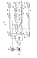
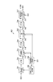
- FIG. 6 is a diagram showing a configuration example in which the base station apparatus eNB according to the present embodiment has one reception antenna.
- the base station apparatus eNB includes a reference signal separation unit 301, an FFT unit 302, a demapping unit 303, a soft canceller unit 304, an equalization unit 305, an IFFT unit 306, a demodulation unit 307, a decoding unit 308, and a replica generation.
- Unit 309 FFT unit 310, IUI extraction unit 311, propagation path estimation unit 312, soft canceller unit 324, equalization unit 325, IFFT unit 326, demodulation unit 327, decoding unit 328, replica generation unit 329, FFT unit 330, IUI An extraction unit 331 is included.
- the reference signal separation unit 301 simultaneously receives the reception signal D21 from the plurality of transmission devices (terminal devices) (from the terminal devices UE2 and UE3 in the present embodiment) by the reception antenna TB1, and transmits the encoded data and the reference signal. Perform separation. At this time, the reference signal separator 301 down-converts the received signal D21 into a baseband signal, and converts it into a digital signal by performing A / D conversion. Further, after removing the cyclic prefix CP from the digital signal, the reference signal demultiplexing unit 301 demultiplexes the reference signal of each transmitting apparatus and outputs the demultiplexed reference signal to the propagation path estimating unit 312. Further, the reference signal separation unit 301 outputs a data signal from which the reference signal is separated to the FFT unit 302.
- propagation path estimation section 312 estimates the propagation path characteristics of each of the plurality of transmission apparatuses from the input reference signal of each transmission apparatus, and outputs them to demapping section 303 and equalization section 305. Also, the propagation path estimation unit 312 sets bandwidth allocation (bandwidth allocation information), coding rate, modulation scheme, and the like for each transmission apparatus based on the estimated propagation path characteristics. At this time, the propagation path estimation unit 312 includes a duplication rate of an assigned band with other transmission apparatuses in order to allow overlapping allocation based on the propagation path characteristics of each transmission apparatus when setting band allocation. Set bandwidth allocation.
- the propagation path estimation unit 312 converts the control information including the set band allocation information, the coding rate, the modulation scheme, and the duplication rate into a signal D22 for feedback, and a modulation unit, a radio unit, and a transmission (not shown) It transmits with respect to each transmitter (terminal device UE2, UE3) via an antenna.
- control information obtained so as to obtain a predetermined error rate by experiment or the like is set in advance corresponding to the propagation path characteristics, and corresponds to the input propagation path characteristics. And output the stored control information.
- the propagation path estimation unit 312 obtains a constraint length and a puncture pattern based on the control information, and outputs the obtained constraint length and puncture pattern to the decoding unit 328.
- the FFT unit 302 converts the data signal from the time domain signal to the frequency domain signal, and outputs the converted frequency signal to the demapping unit 303.
- the demapping unit 303 separates the frequency signal into a signal from each transmission device based on band allocation information that is mapping information when the transmission device is previously transmitted to the transmission device stored therein. That is, the demapping unit 303 separates the signal A from the terminal device UE2 and the signal B from the terminal device UE3. Then, the demapping unit 303 outputs a signal from each transmission device from which the frequency signal is separated to a different detection path.
- the demapping unit 303 outputs the signal A obtained by separating the frequency signal to the soft canceller unit 304, and outputs the signal B to the soft canceller unit 324.
- the frequency signals are simply separated using the mapping information, the frequency signals of some allocated bands that overlap at the time of transmission remain as interference with each other.
- the soft canceller unit 304 includes information related to ISI, which is feedback information from the decoding unit 308, which will be described later, and inter-user interference (IUI: Inter) caused by the other transmission devices from the IUI extraction unit 331 allocating signals to bands. Based on the information of User Interference, ISI and IUI soft replicas are subtracted from the received signal as soft cancellation processing for the separated signal A (signal of a specific transmission device). Thereby, the soft canceller unit 304 performs processing for canceling the ISI and IUI. In this embodiment, ISI and IUI are subtracted and canceled at the same time, but soft replicas of ISI and IUI may be subtracted and canceled individually. Further, the soft canceller unit 304 outputs the soft canceled signal A to the equalization unit 305.
- ISI and IUI are subtracted and canceled at the same time, but soft replicas of ISI and IUI may be subtracted and canceled individually. Further, the soft canceller unit 304 outputs the soft canceled signal A to the equalization unit 305.
- the soft canceller unit 304 does not receive feedback information at the first time, and information on inter-user interference caused by the other transmission apparatus allocating signals to the band redundantly from the IUI extraction unit 331 is not input. For this reason, the soft canceller unit 304 does not perform processing for canceling ISI and IUI.
- the equalization unit 305 compensates for distortion of the radio propagation path such as multiplying the signal A input from the soft canceller unit 304 by the MMSE weight based on the propagation path characteristic estimated by the propagation path estimation unit 312. Processing is performed, and the equalized signal A is output to the IFFT unit 306.
- the IFFT unit 306 converts the equalized signal A input from the equalization unit 305 from a frequency domain signal to a time domain signal, and outputs the processed signal A1 to the demodulation unit 307 as a conversion result. .
- the demodulation unit 307 performs demodulation processing of the modulation symbol on the processing signal A1 input from the IFFT unit 306 in accordance with the modulation method transmitted to the transmission device last time, and the demodulated demodulation signal A2 to the decoding unit 308. Output.
- the decoding unit 308 performs a decoding process on the demodulated signal A2 input from the demodulation unit 307 using control information (encoding information D23) such as an encoding rate notified to the transmission apparatus as control information, and the decoding result is converted into a signal bit.
- the data is output to the replica generation unit 309 as A3.
- the replica generation unit 309 converts the decoded bit into a modulation symbol again in accordance with the modulation method transmitted to the previous transmission apparatus, and outputs the converted symbol to the FFT unit 310 as a replica signal RA.
- the FFT unit 310 converts the replica signal RA input from the replica generation unit 309 from a time domain signal to a frequency domain signal. Then, the FFT unit 310 outputs the conversion result as feedback information to the soft canceller unit 304 and the IUI extraction unit 311.
- the soft canceller unit 304 performs ISI interference cancellation processing on its own signal A based on feedback information input from the FFT unit 310.
- the IUI extraction unit 311 generates an IUI interference replica RA2 from the feedback information input from the FFT unit 310, and outputs this IUI interference replica RA2 to the soft canceller unit 324.
- This interference replica RA2 is used in the soft canceller unit 324 to remove IUI interference caused by the signal A from the signal B transmitted from another communication apparatus, that is, the terminal apparatus UE3.
- the soft canceller unit 324, the equalization unit 325, the IFFT unit 326, the demodulation unit 327, the decoding unit 328, the replica generation unit 329, the FFT unit 330, and the IUI extraction unit 331 also include the soft canceller unit 304 and the equalization unit 305 described above.
- IFFT unit 306, demodulation unit 307, decoding unit 308, replica generation unit 309, FFT unit 310, and IUI extraction unit 311 are processed in the same manner. That is, the soft canceller unit 324 is separated by feedback information from a decoding unit 328 described later and information on inter-user interference caused by other transmitters overlapping the IUI extraction unit 311 and allocating signals to bands.
- Processing for canceling ISI and IUI is performed on the received signal B (signal of a specific transmission device) by soft cancellation processing. Further, the soft canceller unit 324 outputs the soft canceled signal B to the equalization unit 325. However, since the soft canceller unit 324 has no feedback information in the first time, and information on inter-user interference caused by other transmitters duplicatingly assigning signals to bands from the IUI extracting unit 311 is not input. Processing to cancel ISI and IUI is not performed.
- the equalization unit 325 performs equalization to compensate for distortion of the wireless channel such as multiplying the signal B input from the soft canceller unit 324 by the MMSE weight based on the channel characteristics estimated by the channel estimation unit 312. Process. Then, the equalization unit 325 outputs the equalized signal B to the IFFT unit 326.
- the IFFT unit 326 converts the equalized signal B input from the equalization unit 325 from a frequency domain signal to a time domain signal, and outputs the processed signal B1 to the demodulation unit 327 as a conversion result. .
- the demodulation unit 327 performs demodulation processing of the modulation symbol on the processing signal B1 input from the IFFT unit 326 in accordance with the modulation method transmitted to the transmission device last time, and the demodulated demodulated signal B2 to the decoding unit 328. Output.
- the decoding unit 328 uses the coding rate notified to the transmission apparatus as control information with respect to the demodulated signal B2 input from the demodulation unit 327, and the constraint length and puncture pattern information obtained from the control information by the propagation path estimation unit 312.
- the decoding process is performed, and the decoding result is output to the replica generation unit 329 as the signal bit B3.
- Replica generation section 329 converts the decoded bits into modulation symbols again in accordance with the modulation method transmitted to the previous transmission apparatus, and outputs the result to FFT section 330 as replica signal RB.
- the FFT unit 330 converts the replica RB signal input from the replica generation unit 329 from a time domain signal to a frequency domain signal, and uses the conversion result as feedback information for the soft canceller unit 324 and the IUI extraction unit 331. Output.
- the soft canceller unit 324 performs ISI interference cancellation processing on its own signal B based on feedback information input from the FFT unit 330.
- the IUI extraction unit 331 generates an IUI interference replica RB2 from the feedback information input from the FFT unit 330, and outputs this IUI interference replica RB2 to the soft canceller unit 304.
- This interference replica RB2 is used in the soft canceller unit 304 to remove IUI interference caused by the signal B from the signal A transmitted from another communication device (that is, the terminal device UE2).
- the decoding process with the transmission signal from the terminal device UE3 is repeatedly performed.
- the decoding process of the transmission signal for each transmission device is repeated an arbitrary number of times or a predetermined number of times.
- the determination unit (not shown) provided in the subsequent stage of each of the decoding units 308 and 328 performs a hard decision on the decoded bits to obtain decoded data for each transmission device.
- each of the encoding method determination units 107 and 708 is a turbo encoding unit in accordance with a change in convergence of iterative processing in turbo equalization due to an increase in band duplication rate or multi-level modulation schemes.
- the constraint lengths of the encoding unit 201 and the encoding unit 204 which are component encoders (RSC encoders) 101 and 701 are determined.
- both the constraint lengths of the encoding unit 201 and the encoding unit 204 are shortened, the convergence of the iterative process in the turbo equalization in the system performing each decoding process described above is improved. Error correction capability deteriorates. Conversely, if the constraint lengths of both encoding units are increased, the error correction capability for the received signal is improved and increased, but the convergence of the iterative process in turbo equalization is deteriorated. Therefore, it is preferable to determine the constraint lengths of the encoding unit 201 and the encoding unit 204 that are component encoders in consideration of the convergence of the iterative processing in turbo equalization based on the band overlap rate, the number of modulation levels, and the encoding rate.
- the modulation multi-level number is input from the receiver as the number of bits to be transmitted in one symbol in the multi-level modulation system and the modulation system.
- the two component encoders (the encoding unit 201 and the encoding unit 204) in the turbo encoding units 101 and 701 use different constraint lengths or change the constraint length of only one of them, thereby improving the error correction capability. It is desirable to determine a coding method with good convergence of iterative processing in turbo equalization while suppressing deterioration.
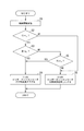
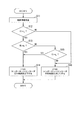
- FIG. 7 is a flowchart illustrating an operation example of the coding rate determination method of the coding method determination unit 107.
- Step S1 The control information receiving unit 108 receives the control information notified from the base station device eNB that is a receiving device, and outputs the received control information to the encoding method determining unit 107.
- the control information notified from the receiving device includes a coding rate, the number of modulation levels, and a duplication rate of band assignment with other transmitting devices.
- the coding rate is C
- the modulation multi-level number is M
- the overlapping rate of band allocation with other transmission apparatuses is R.
- Step S2 Coding method determining unit 107, it is determined whether the coding rate C included in the received control information is higher than r c threshold worsen high encoding rate of convergence.
- the encoding method determination unit 107 the relationship between the threshold r c of the coding rate C and a coding rate is the case of C> r c, the process proceeds to step S3.
- the encoding method determination unit 107 the relationship between the threshold r c of the coding rate C and a coding rate is the case of C ⁇ r c, the process proceeds to step S6.
- Step S3 If the encoding method determining unit 107 determines that the encoding rate is high in step S2, the encoding method determining unit 107 determines whether the notified modulation multi-level number M is larger than the multi-level number m 1 that causes poor convergence. .
- the modulation multilevel number of QPSK is 2
- the modulation multilevel number of 16QAM is 4.
- the encoding method determination unit 107 proceeds with the process to step S4.
- the encoding method determination unit 107 advances the processing to step S5.
- Step S4 The encoding method determination unit 107 shortens the constraint length of either the encoding unit 201 or the encoding unit 204. Thereby, the convergence of the turbo decoding process is improved. For example, the encoding method determination unit 107 lowers the constraint length in the encoding unit 204 by one from the constraint length 4 to the constraint length 3 and outputs the obtained constraint length to the encoding unit 204. Then, the encoding unit 204 changes the configuration of the internal logic operation circuit so as to change the constraint length as the component encoder, corresponding to the constraint length input from the encoding method determination unit 107.
- the encoding unit 204 changes the connection configuration of the delay circuit and the adder as illustrated in FIGS. 5A to 5B.
- the RSC encoder shown in FIG. 5A and FIG. 5B is included in the encoding unit, that is, the encoding unit has a plurality of RSC encoders with different constraint lengths, and the encoding unit receives from the encoding method determination unit 107.
- the RSC encoder used to generate the error correction code is changed according to the constraint length.
- the encoding method determination unit 107 determines in advance which code part's constraint length is to be changed and how much the constraint length is to be changed.
- the difference between the modulation level M and multi-level number m 1, the difference between the coding rate C and the threshold value r c, due to the combination of a difference such as the overlap rate R and a threshold r 0, constraint length to change A table for setting the length (one or a plurality of two or more) may be provided.
- the constraint length corresponding to the combination may be read from this table and adjusted by the read constraint length.
- the constraint length is decreased by one, “YES” in step S 2, and if “YES” in step S 3, the constraint length is decreased by two.
- the number of constraint lengths to be changed may be set according to the combination to be compared, such as lowering, and the constraint length may be selected based on the combination.
- Step S5 Coding method determining unit 107 is higher overlap rates than r 0 overlaying rate R of notified from the receiver band is convergent worsen threshold and determines whether or not.
- the encoding method determination unit 107 advances the process to step S4.
- the encoding method determination unit 107 proceeds with the process to step S6.
- Step S6 Coding method determining unit 107, if the coding rate of the coding rate C or less r c, there is no need improvement of convergence by changing the constraint length. Therefore, the encoding method determination unit 107 is set to use the same constraint length (for example, constraint length 4) without changing the constraint lengths of the encoding units 201 and 204 that are the two component encoders.
- constraint length for example, constraint length 4
- the constraint length of the component encoder is sequentially changed according to the band duplication rate, the modulation multi-level number, and the coding rate. Therefore, for example, when they are the same constraint length, any one is changed and a difference is given. Therefore, conventionally, it is possible to use a coding rate that exceeds a threshold that degrades convergence, and a duplication rate that exceeds a threshold that degrades convergence. For this reason, it is possible to improve error rate characteristics in various modulation communication systems. Further, determination of the threshold value r c, constraint length with m 1, r o of a condition value deteriorating the convergence of iteration in the turbo equalization is required in the receiver.
- a plurality of component encoders may have turbo code units having the same constraint length and turbo code units having different constraint lengths, and the turbo code unit used for error correction may be determined according to the conditions shown in FIG.
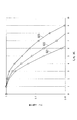
- FIG. 8 is a graph showing a relationship between simulation results of FER (Frame Error Rate) when E / 4 and E b / N 0 (average transmission signal energy to noise power spectral density ratio per information bit). is there. Further, the number of iterations in turbo equalization in the receiver is 8 times, and the number of iterations in turbo decoding is 8. In FIG.
- the constraint lengths (K 1 , K 2 ) are obtained when the encoding units 201 and 204, which are two component encoders in the turbo encoding unit 101, are set to the constraint length K 1 and the constraint length K 2 , respectively. Is shown.
- the constraint lengths (3, 3) indicate characteristics when turbo coding is performed by connecting component encoders with constraint length 3 in parallel.
- the characteristic G21 shows the case of the turbo code constraint length (4, 3).
- a characteristic G22 indicates the case of the turbo code constraint length (4, 4).
- a characteristic G23 indicates a case where the turbo code constraint length is (3, 3).
- the constraint length 3 of the encoding units 201 and 204 in the turbo coding unit 101 is set to 3 or when the constraint length is 4, the constraint length 3 and the constraint length are limited when there is a lot of interference as in this embodiment.
- a component encoder having a constraint length different from the length 4 is provided in parallel, and a turbo code formed by concatenating the codes generated in each is applied.
- the communication characteristics are improved because the FER is lowered even when the noise ratio is high.
- E b / N 0 is 6 dB
- the frame error rate is 0.166 when the constraint length of the two component encoders is (3, 3).
- the constraint length is (4, 4)
- the frame error rate is 0.052.
- the constraint length is (4, 3)
- the frame error rate is 0.013. In other words, the frame error rate is remarkably improved.
- the turbo code unit 701 has the same configuration as the turbo code unit 101.
- the constraint length for each component encoder in the turbo coding unit 101 is changed in consideration of interference due to IUI and ISI.
- the interference can be applied when the interference is suppressed by iterative processing such as turbo equalization.
- the present invention is also applicable to a downlink in which the transmission device is a plurality of base station devices eNB and the reception device is a UE.
- the transmission apparatus can also determine the bandwidth allocation, modulation scheme, duplication rate, etc., in addition to the control information used for data transmission from the transmission apparatus to the reception apparatus, the constraint of the component encoder used for the error correction code This can be realized by notifying the length.
- the description has been given assuming that the number of transmission apparatuses is two of the terminal apparatuses UE2 and UE3.
- the receiving apparatus can be applied by processing the same number of decoding units 308 from the soft canceller 304 in FIG. For example, when there are three terminal devices, in the soft canceller unit 304, only the soft replica fed back from the decoding unit 308 becomes ISI information to be canceled.
- the soft replica fed back from each of the other two decoders is IUI information.
- the ISI information and the IUI information are used for cancellation processing for interference between symbols and interference between users, respectively.
- the transmission method is a single carrier and turbo equalization is applied to reception processing
- the present invention can also be applied to a case where the reception apparatus performs iterative processing of an interference canceller and a decoding unit even in multicarrier.
- the modulation unit 102 may output the modulated modulation symbol to the mapping unit 104.
- mapping section 104 may map the modulation symbol to each frequency according to the band allocation information and output the allocated data signal to IFFT section 105. Since the subsequent processing is the same as the transmission signal processing already described, the description thereof is omitted.
- the receiving apparatus of the base station eNB1 when the transmission scheme is multicarrier has the configuration shown in FIG.
- the receiving apparatus of FIG. 9 is different from the receiving apparatus of FIG. 6 in that the equalization units 305 and 325 and the IFFT units 306 and 326 are eliminated, and signal detection units 351 and 352 are newly added.
- Each of the signal detection units 351 and 352 performs phase detection of the demapped signal input from the demapping unit 303 based on the estimated value of the channel characteristics input from the channel estimation unit 312, Output to the cancellers 304 and 325.
- the other processes are the same as those already described, and thus the description thereof is omitted.
- the encoding method determination unit 107 of the present embodiment based on communication parameters including items such as an encoding rate, a modulation scheme (the number of modulation multi-values), and an overlapping rate of band allocation with other transmission apparatuses,
- the constraint length for each component encoder is determined by comparison processing shown in FIG. 7 with a condition value that deteriorates the convergence of the iterative processing in turbo equalization corresponding to each item. Unlike the configuration described above, this constraint length is set by the propagation path estimation unit 312 on the receiving apparatus side, and the constraint length for each component encoder of each transmission apparatus is set based on the propagation path between each transmission apparatus and the encoding rate.
- the modulation scheme, band duplication rate, and the like, and the determined constraint length may be notified to the transmission apparatus as control information.
- the control information may include the number of reception antennas of the reception apparatus, and the constraint length may be determined in the same manner as in the second embodiment described later.
- the receiving apparatus does not notify the transmitting apparatus of the band duplication rate, and the encoding method determining unit 107 of the transmitting apparatus supports either or both of the encoding rate and the modulation method, and the respective items.
- the encoding method determination unit 107 may be configured to compare with a condition value that deteriorates the convergence of the iterative process in turbo equalization and determine the constraint length from the comparison result.
- the receiving apparatus transmits only the band duplication rate to the transmitting apparatus, and the transmitting apparatus deteriorates the band duplication rate and the convergence of iterative processing in turbo equalization.
- the encoding method determination unit 107 may be configured to compare the condition value and determine the constraint length of the component encoder from the comparison result. Furthermore, in the determination of the constraint length, the configuration of the present embodiment has been described with respect to an example in which the constraint length is shortened by one component encoder in order to improve convergence. However, when two component encoders in the turbo coding unit 101 (or 701) use the same constraint length, when the constraint length is short, for example, 3, only one component encoder is opposite to this embodiment. The constraint length may be increased, and the two component encoders may be configured to use different constraint lengths.
- this embodiment in a receiving apparatus that uses repetitive processing such as turbo equalization, when a high coding rate or a high overlapping rate of band allocation is obtained, or the number of modulation multilevels is constant. Even in an environment where the convergence of the iterative process in the turbo equalization such as the above value becomes worse, the convergence can be improved by configuring the component encoders in the turbo coding unit with different constraint lengths. Thereby, frequency utilization efficiency can be improved.
- a puncture pattern is determined from the coding constraint length and the coding rate, and a turbo code is generated, so that various modulation schemes, communication schemes, and channel characteristics can be obtained. However, the error rate characteristics can be improved even in an environment where there is much interference.
- the transmission device is a terminal device UE1 (see FIG. 1) that performs MIMO transmission using multiple antennas
- the reception device is a base station device eNB2.
- the turbo process is performed in an environment where the convergence of the iterative process in turbo equalization such as a high coding rate, multilevel modulation, and a high correlation value between antennas is poor.
- a configuration example in which the convergence is improved by configuring the component encoders in the encoding unit with different constraint lengths will be described with reference to FIG.
- FIG. 10 is a block diagram illustrating a configuration example of the terminal device UE1 which is a transmission device according to the second embodiment.
- the terminal device UE1 includes a turbo coding unit 701, an S / P (Serial / Parallel) unit 702, a modulation unit 703, an FFT unit 704, a mapping unit 705, an IFFT unit 706, a reference signal multiplexing unit 707, and an encoding method.
- a determining unit 708, a control information receiving unit 709, a modulating unit 713, an FFT unit 714, a mapping unit 715, an IFFT unit 716, and a reference signal multiplexing unit 717 are provided.
- the control information receiving unit 709 receives control information D31 transmitted from the base station device eNB2.
- the control information received by the control information receiving unit 709 includes a coding rate, a modulation scheme, band allocation information, information on correlation values between antennas, and the like.
- the control information receiving unit 709 outputs information such as the coding rate, modulation scheme, and band duplication rate included in the control information to the coding method determining unit 708. Further, the control information receiving unit 709 outputs the modulation scheme included in the control information to the modulation units 703 and 713. Further, the control information receiving unit 709 outputs band allocation information to the mapping units 705 and 715.
- the encoding method determination unit 708 is based on the information regarding the coding rate, modulation scheme, and correlation value between antennas notified as control information, similarly to the encoding method determination unit 107 (and 708) shown in FIG. A constraint length for each component encoder in the puncture pattern and turbo encoding unit 701 is determined. Then, the encoding method determination unit 708 outputs the determined puncture pattern and constraint length to the turbo encoding unit 701.
- the turbo coding unit 701 has the same configuration as the turbo coding unit 101 in FIG.
- the turbo encoding unit 701 performs encoding using the encoding method determined by the encoding method determining unit 708, that is, encodes the data bit D32 using the puncture pattern and the constraint length, similarly to the turbo encoding unit 101 illustrated in FIG. . Then, the turbo coding unit 701 outputs the coded bits to the S / P unit 702.
- the S / P unit 702 performs S / P conversion of the encoded bits input from the turbo encoding unit 701 into parallel 2 bits in the input order, and converts one bit of the parallel 2 bits to the modulation unit 703 and the other Are output to the modulation unit 713 as transmission bits.
- Each of the two parallel bits becomes a transmission bit transmitted from each transmission antenna, that is, from the transmission antenna T1 (see FIG. 1) and the transmission antenna T2 (see FIG. 1).
- Each of modulation sections 703 and 713 generates a modulation symbol by a modulation scheme corresponding to the modulation scheme information input from control information reception section 709.
- Modulation section 703 outputs the generated modulation symbol to FFT section 704.
- modulation section 713 outputs the generated modulation symbol to FFT section 714.
- the FFT unit 704 converts the modulation symbol input from the modulation unit 703 from a time domain to a frequency domain data signal, and outputs the converted data signal to the mapping unit 705.
- FFT section 714 converts the modulation symbol input from modulation section 713 from a time domain to a frequency domain data signal, and outputs the converted data signal to mapping section 715.
- Mapping section 705 performs processing for allocating frequency domain data signals to corresponding bands based on band allocation information input from control information receiving section 709, and outputs the allocated data signals to IFFT section 706.
- Mapping section 715 performs processing for allocating frequency domain data signals to corresponding bands based on band allocation information input from control information receiving section 709, and outputs the allocated data signals to IFFT section 716. .
- IFFT section 706 converts the data signal in the frequency domain into a transmission signal in the time domain, and outputs the converted transmission signal to reference signal multiplexing section 707.
- IFFT section 716 converts the frequency domain data signal into a time domain transmission signal and outputs the converted transmission signal to reference signal multiplexing section 717.
- the reference signal multiplexing unit 707 performs a process of multiplexing the reference signal D33 (a pilot signal whose code pattern is known) on the transmission signal in the time domain, and outputs the signal as a transmission signal D34 for the transmission antenna T1.
- the reference signal multiplexing unit 717 performs a process of multiplexing the reference signal D33 on the transmission signal in the time domain, and outputs it as a transmission signal D35 for the transmission antenna T2.
- the transmission signal D35 from the reference signal multiplexing unit 717 is inserted with a cyclic prefix CP, converted into an analog signal by D / A conversion, and then up-converted to a radio frequency.
- the up-converted signal is amplified to transmission power by the power amplifier PA and then transmitted from the transmission antenna T2.
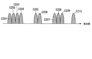
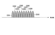
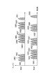
- a plurality of transmission antennas transmission antenna T1, transmission antenna T2 use the same time and the same frequency. Therefore, discrete band allocation as shown in FIG. 11 or continuous band allocation in the example of FIG. 12 is performed.
- FIG. 11 shows an example of allocation of discrete bands to the transmission antenna T1 and the transmission antenna T2. That is, FIG.
- FIG. 11 shows a case where 10 subcarriers C201 to C210 existing in discrete bands are assigned to the transmission antenna T1 and the transmission antenna T2.
- FIG. 12 shows an example of continuous band allocation to the transmission antenna T1 and the transmission antenna T2. That is, FIG. 12 shows a case where ten subcarriers C301 to C310 existing in a continuous band are assigned to the transmission antenna T1 and the transmission antenna T2.
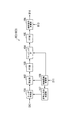
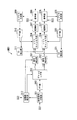
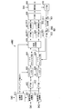
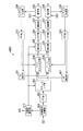
- FIG. 13 is a block diagram illustrating an example of a receiving device of the base station device eNB2 in the present embodiment.
- a receiving apparatus base station apparatus eNB2 having two receiving antennas will be described as in the case shown in FIG.
- the receiving device base station device eNB2 may have three or more receiving antennas.
- the base station apparatus eNB2 includes a reference signal separation unit 801, an FFT unit 802, a demapping unit 803, a soft canceller unit 804, a MIMO separation unit 805, an IFFT unit 806, a demodulation unit 807, a P / S unit 808, and a decoding Unit 809, S / P unit 810, replica generation unit 811, FFT unit 812, propagation path estimation unit 813, reference signal separation unit 821, FFT unit 822, demapping unit 823, soft canceller unit 824, IFFT unit 826, demodulation unit 827, a replica generation unit 831, and an FFT unit 832.
- the reference signal separation unit 801 receives the reception signal D41 from the transmission device (terminal device UE1) by the reception antenna TB1, and separates the encoded data from the reference signal. Further, the reference signal separation unit 821 receives the reception signal D42 from the transmission device (terminal device UE1) by the reception antenna TB2, and separates the encoded data from the reference signal. Here, each of the reception antenna TB1 and the reception antenna TB2 receives a reception signal from the terminal device UE1 at the same time.
- the reference signal separation unit 801 down-converts the received signal D41 into a baseband signal, converts the received signal D41 into a digital signal by performing A / D conversion, and outputs the digital signal to the FFT unit 802.
- the reference signal separation unit 821 down-converts the received signal D42 received into a baseband signal, converts the received signal D42 into a digital signal by performing A / D conversion, and outputs the digital signal to the FFT unit 822. . Also, each of the reference signal separation units 801 and 821 removes the cyclic prefix from the received signals D41 and D42, separates the reference signal from the digital signal, and outputs the separated reference signal to the propagation path estimation unit 813. To do.
- the propagation path estimation unit 813 estimates the propagation path characteristics of each of the plurality of transmission apparatuses from the input reference signal of each transmission apparatus, and outputs them to the MIMO separation unit 805 and the demapping units 803 and 823. Also, the propagation path estimation unit 813 sets band allocation (band allocation information), coding rate, modulation method, and the like for each transmission apparatus based on the estimated propagation path characteristics, and calculates a correlation value between antennas. To do. Then, the propagation path estimation unit 813 converts the control information D43 including the set band allocation information, the coding rate, the modulation scheme, and the correlation value between the antennas into a signal to be fed back. Then, the propagation path estimation unit 813 transmits the converted control information D43 to the transmission device (terminal device UE1) via a modulation unit, a radio unit, and a transmission antenna (not shown).
- the transmission device terminal device UE1
- Each of FFTs 802 and 822 converts a time-domain signal into a frequency-domain signal, and outputs the conversion result signals to demapping units 803 and 823, respectively, similarly to FFT unit 302 in FIG.
- the demapping units 803 and 823 receive signals from the respective transmission devices based on the mapping information input from the propagation path estimation unit 813 and transmitted to the previous transmission device stored therein. To separate. Then, the demapping units 803 and 823 output the separated signals to the soft canceller units 804 and 824, respectively.
- Each of the soft canceller units 804 and 824 performs processing similar to that of the soft canceller units 304 and 324 in FIG. 6 and outputs a signal obtained by canceling the ISI and IUI to the MIMO separation unit 805.
- MIMO separation section 805 separates the spatially multiplexed signals based on the propagation path information estimated from the reference signals received from reception antennas TB1 and TB2 input from propagation path estimation section 813. Then, the MIMO separation unit 805 outputs the separated signal of the reception antenna TB1 to the IFFT unit 806 and outputs the signal of the reception antenna TB2 to the IFFT unit 826, for example.
- the IFFT unit 806 converts the signal of the reception antenna TB1 input from the MIMO separation unit 805 from a frequency domain signal to a time domain signal, and outputs the processed signal B1 to the demodulation unit 807 as a conversion result.
- IFFT section 826 converts the signal of reception antenna TB2 input from MIMO separation section 805 from a frequency domain signal to a time domain signal, and outputs processed signal B2 as a conversion result to demodulation section 827. To do.
- the demodulation unit 807 performs demodulation processing of the modulation symbol on the processing signal B11 input from the IFFT unit 806 in accordance with the modulation method transmitted to the transmission device last time, and the demodulated demodulated signal B12 is transmitted to the P / S unit. Output to 808.
- the demodulation unit 827 performs demodulation processing of the modulation symbol on the processing signal B21 input from the IFFT unit 826 in accordance with the modulation method transmitted to the transmission device last time, and the demodulated demodulated signal B22 is converted into the P / S unit. Output to 808.
- the P / S unit 808 performs the S / P conversion of the demodulated signal B12 input from the demodulating unit 807 and the demodulated signal B22 input from the demodulating unit 827 in the S / P unit 702 of FIG. P / S conversion and output to the decoding unit 809.
- the decoding unit 809 performs a decoding process on the P / S converted signal input from the P / S unit 808 using the constraint length and coding rate information (encoding information D44) notified to the transmission apparatus as control information.
- the decoding result is output to the S / P unit 810.
- the S / P unit 810 performs S / P conversion similar to the S / P unit 702 of FIG. 10, outputs a signal bit string corresponding to the processing signal B11 to the replica generation unit 811, and a signal bit string corresponding to the processing signal B21 Is output to the replica generation unit 831. Similar to the replica generation unit 309 in FIG. 6, the replica generation unit 811 generates the replica signal RB1 from the signal bit string corresponding to the processing signal B11 and outputs the generated replica signal RB1 to the FFT unit 812. Similarly, the replica generation unit 831 generates the replica signal RB2 from the signal bit string corresponding to the processing signal B21, and outputs the generated replica signal RB2 to the FFT unit 832, similarly to the replica generation unit 309 of FIG. .
- the FFT unit 812 converts the replica signal RB1 input from the replica generation unit 811 from a time domain signal to a frequency domain signal. Then, the FFT unit 812 outputs the conversion result to the soft canceller unit 824 as feedback information.
- the soft canceller unit 804 performs ISI interference cancellation processing on its own processing signal B11 based on feedback information input from the FFT unit 812.
- the FFT unit 832 converts the replica signal RB2 input from the replica generation unit 831 from a time domain signal to a frequency domain signal. Then, the FFT unit 832 outputs the conversion result to the soft canceller unit 824 as feedback information.
- the soft canceller unit 824 performs ISI interference cancellation processing on its own processing signal B21 based on feedback information input from the FFT unit 832. Since the subsequent decoding process is the same as the process of each corresponding unit in FIG.
- turbo equalization processing is performed in which the receiving apparatus feeds back the output of the decoding unit 809 to the soft canceller units 804 and 824 for the purpose of removing ISI.
- turbo equalization using a turbo decoding unit that has a high coding rate, a high correlation value between antennas, and a large amount of residual antenna interference (IAI: Inter Antenna Interference).
- the encoding method determining unit 708 determines the constraint lengths of the encoding unit 201 (FIG. 4) and the encoding unit 204 (FIG. 4), which are component encoders inside the turbo encoding unit, in accordance with the change in convergence of the iterative process in FIG. To do.
- the encoding method determination unit 708 includes a coding unit 201, which is a component encoder, according to a change in convergence of iterative processing in turbo equalization based on correlation values between antennas, the number of modulation multi-values, and a coding rate.
- the constraint length of the encoding unit 204 is determined. An example of this determination method will be described with reference to FIG. FIG. 14 is a flowchart for obtaining the constraint length based on the correlation value between antennas, the number of modulation levels, and the coding rate.
- Step S11 The control information receiving unit 709 receives the control information notified from the base station apparatus eNB2, and outputs the received control information to the encoding method determining unit 708. In the control information notified from the receiving apparatus, the coding rate is C, the modulation multi-level number is M, and the correlation value between antennas is A.
- Step S12 Coding method determining unit 708, the coding rate C included in the received control information, is whether it is a higher value than the threshold value r c is the high code rate deteriorates the convergence or (C> r c Whether or not).
- the encoding method determination unit 708, the coding rate C exceeds the threshold value r c (C> r c) case, the process proceeds to step S13.
- the encoding method determination unit 708 determines that there is no need to improve convergence by changing the constraint length, and the process proceeds to step S16. Proceed to
- Step S13 The encoding method determination unit 708 determines whether or not the notified modulation multilevel number M is a value greater than the multilevel number m 1 that has poor convergence (whether or not M> m 1 ). At this time, when the modulation multilevel number M exceeds the multilevel number m 1 (M> m 1 ), the encoding method determination unit 708 determines that the convergence is poor and advances the process to step S14. On the other hand, when the modulation multilevel number M is equal to or less than the multilevel number m 1 (M ⁇ m 1 ), the encoding method determination unit 708 advances the process to step S15.
- Step S14 The encoding method determination unit 708 lowers the constraint length of either the encoding unit 201 or the encoding unit 204. Thereby, the convergence of the turbo decoding process is improved. For example, the encoding method determination unit 708 lowers the constraint length in the encoding unit 204 by one from the constraint length 4 to the constraint length 3, and the obtained constraint length is reduced to the encoding unit 204 (see FIG. Output to 4). Then, the encoding unit 204 changes the configuration of the internal logic operation circuit so as to change the constraint length as the component encoder in accordance with the constraint length input from the encoding method determination unit 708.
- the encoding unit 204 changes the connection configuration of the delay circuit and the adder as illustrated in FIGS. 5A to 5B.
- the RSC encoder shown in FIG. 5A and FIG. 5B is included in the encoding unit, that is, the encoding unit has a plurality of RSC encoders with different constraint lengths, and the encoding unit receives from the encoding method determination unit 708.
- the RSC encoder used to generate the error correction code is changed according to the constraint length.
- the constraint length is changed and how much the constraint length is changed are set in advance in the encoding method determination unit 708.
- Step S15 Coding method determining unit 708 determines the correlation value A is whether high correlation value than worsen threshold a c convergent between notified from the receiving apparatus antenna (whether A> a c) .
- the encoding method determination unit 708 determines that the convergence is poor and advances the process to step S14.
- the encoding method determination unit 708 determines that there is no need to improve convergence by changing the constraint length, and performs the processing. Proceed to step S16.
- Step S16 Since the encoding method determining unit 708 does not need to improve convergence by changing the constraint length, the two component encoders of the encoding unit 201 and the encoding unit 204 use the same constraint length. For example, the encoding method determination unit 708 sets the constraint length of each of the encoding unit 201 and the encoding unit 204 to 4, and ends the constraint length control process. Further, since it is necessary for the receiver to determine the constraint length using the threshold values r c , m 1 and a c used in the flowchart shown in FIG. 14, the three parameters have the same value in both the transmitting device and the receiving device in advance. Is decided.
- the constraint length for each of the turbo encoding units 201 and 204 which are component encoders in the turbo encoding unit 701 is changed in consideration of interference due to IAI and ISI.
- the interference is not described in the present embodiment, it can be applied when the interference is suppressed by iterative processing such as turbo equalization.
- it can be applied also to a downlink.
- the description has been given assuming that the number of transmission antennas of the transmission apparatus is two, the present invention can be similarly applied to the case of three or more.
- the transmission method is a single carrier and turbo equalization is applied to the reception processing has been described, as in the case of the first embodiment, the reception apparatus performs the repetition processing of the interference canceller and the decoding unit even in multicarrier Is applicable.
- turbo equalization corresponding to each item is performed based on communication parameters including items such as a correlation value between antennas, a coding rate, and a modulation scheme (modulation multi-level number).
- the constraint length for each component encoder is determined by the process shown in FIG. This constraint length may be determined for each component encoder of each transmitting device on the receiving device side and notified as control information.
- the receiving apparatus does not notify the correlation value between the antennas to the transmitting apparatus, and the transmitting apparatus repeats processing in one or both of the coding rate and the modulation method, and turbo equalization corresponding to each item.
- the encoding method determination unit 708 may be configured to perform comparison with a condition value that deteriorates the convergence of and determine the constraint length from the comparison result.
- the encoding method determining unit 708 may be configured to determine only from the correlation value between antennas. Furthermore, the determination of the constraint length has been described in the present embodiment with respect to an example in which the constraint length is shortened by one component encoder in order to improve convergence. However, when two component encoders use the same constraint length, when the constraint length is short, for example, 3, the constraint length is increased by one component encoder and different constraint lengths are used by the two component encoders. Alternatively, the encoding method determination unit 708 may be configured.
- the modulation multilevel number is a certain value or more.
- the convergence can be improved by configuring the component encoders in the turbo coding unit with different constraint lengths, and the frequency utilization efficiency can be improved.
- the transmission apparatus performs transmission using multiple antennas, and assigns a subcarrier having a high propagation path gain to each antenna. And when only some of the subcarriers overlap, when the receiving device uses iterative processing such as turbo equalization, a high coding rate, multi-level modulation, a high overlapping rate of bands used between antennas, etc. Convergence is improved by configuring the component encoders in the turbo code unit with different constraint lengths in an environment where the convergence of the iterative process in turbo equalization is poor.
- FIG. 16 is a diagram illustrating a configuration example of a receiving device of the base station eNB3 according to the present embodiment.
- FIG. 15 shows an example in which a band is assigned to each antenna according to this embodiment.
- the same band is allocated to each antenna, but in this embodiment, a different band can be allocated to each antenna.
- the upper diagram (assignment 1) in FIG. 15 shows the assignment of the antenna T1.
- subcarriers C401 to C411 are assigned to antenna T1.
- the lower part of FIG. 15 shows the assignment of antenna T2.
- subcarriers C421 to C431 are assigned to antenna T2.
- the configuration of the transmission device (terminal device) in this case is the same as that in FIG.
- the receiving apparatus is the same except that the IUI extraction unit 311 and the IUI extraction unit 331 in FIG. 6 are replaced with an IAI extraction unit 401 and an IAI extraction unit 431.
- the IAI extraction unit 401 and the IAI extraction unit 431 each generate an IAI interference replica used for removing IAI (Inter Antenna Interference).
- the IAI extraction unit 401 generates an IAI interference replica from the feedback information input from the FFT unit 310, and outputs the IAI interference replica to the soft canceller unit 324.
- the IAI extraction unit 431 generates an IAI interference replica from the feedback information input from the FFT unit 330 and outputs this IAI interference replica to the soft canceller unit 304.
- the method for determining the constraint length for each component encoder in the turbo encoder in the encoding method determining unit 107 is determined by the flowchart of FIG. 7 as in the first embodiment.
- the constraint length for each component encoder in the turbo code unit is changed in consideration of interference due to IAI and ISI.
- it can be applied when the interference is suppressed by iterative processing such as turbo equalization.
- turbo equalization although demonstrated as an uplink which uses UE1 as a transmitter and base station apparatus eNB3 as a receiver, it is applicable also to a downlink.
- the number of antennas has been described as two, the present invention can be similarly applied to a case of three or more.
- the transmission method is a single carrier and turbo equalization is applied to the reception processing has been described.
- iterative processing of the interference canceller and the decoding unit is performed by the reception device. Applicable when doing.
- the constraint length for each component encoder is determined by the processing shown in FIG. 7 in which comparison is made with a condition value that deteriorates the convergence of iterative processing in turbo equalization corresponding to each item. ing.
- the constraint length may be determined on the reception device side for each component encoder of each transmission device, and notified to the transmission device as control information.
- the receiving apparatus does not notify the transmitting apparatus of the band duplication rate, and the transmitting apparatus performs the repetition process in the turbo equalization corresponding to each item of the coding rate and / or the modulation method.
- the encoding method determination unit 107 may be configured to perform comparison with a condition value that deteriorates convergence and determine the constraint length from the comparison result.
- the encoding method determination unit 107 may be configured to determine only from the band overlap rate. Furthermore, in the determination of the constraint length, the configuration of this embodiment has been described with respect to an example in which the constraint length is shortened by one component encoder in order to improve convergence. However, when two component encoders use the same constraint length, when the constraint length is short, for example, 3, the constraint length is increased by only one component encoder, as opposed to the present embodiment. You may comprise so that a different constraint length may be used with a component encoder.
- the reception device uses an iterative process such as turbo equalization.
- turbo equalization an iterative process
- the convergence is improved by configuring the component encoders in the turbo coding unit with different constraint lengths in an environment where the number of receiving antennas of the receiving apparatus is small and the convergence of the repetition process in turbo equalization is poor.
- the base station apparatus eNB FIG. 6
- the base station apparatus eNB adds the number of antennas in the receiving apparatus to the information such as the coding rate, the modulation multi-value number, the band allocation information (or the correlation value between the antennas), etc. as control information, Notification is made to the terminal devices UE2 and UE3 (or UE1) which are transmitting devices. Since the processing for controlling the constraint length in the encoding method determination unit 107 and the encoding method determination unit 708 is the same, the encoding method determination unit 107 will be described as an example.
- FIG. 17 is a flowchart showing an operation example of the constraint length control processing performed by the encoding method determination unit 107 (and 708) in the present embodiment.
- Step S21 The control information receiving unit 108 receives the control information notified from the receiving device of the base station apparatus eNB, and outputs the received control information to the encoding method determining unit 107.
- the coding rate is C
- the modulation multi-level number is M
- the number of antennas is A RX NUM .
- Step S22 Coding method determining unit 107, the coding rate C included in the received control information, is whether it is a higher value than the threshold value r c is the high code rate deteriorates the convergence or (C> r c Whether or not).
- the encoding method determination unit 107, the coding rate C exceeds the threshold value r c (C> r c) case, the process proceeds to step S23.
- the encoding method determination unit 107 determines that the convergence is not improved by changing the constraint length, and the process is performed in step S26. Proceed to
- Step S23 Coding method determining unit 107 determines whether the notified multi-level number m 1 greater than the modulation multi-level number M becomes poor convergence (M> whether m 1). At this time, when the modulation multilevel number M exceeds the multilevel number m 1 (M> m 1 ), the encoding method determination unit 107 determines that the convergence is poor and advances the process to step S24. On the other hand, when the modulation multilevel number M is equal to or less than the multilevel number m 1 (M ⁇ m 1 ), the encoding method determination unit 107 advances the process to step S25.
- Step S24 The encoding method determination unit 107 decreases the constraint length of either the encoding unit 201 or the encoding unit 204. Thereby, the convergence of the turbo decoding process is improved. For example, the encoding method determination unit 107 decreases the constraint length in the encoding unit 204 by one from the constraint length 4 to the constraint length 3, and outputs the obtained constraint length to the encoder 204. Then, the encoding unit 204 changes the configuration of the internal logic operation circuit so as to change the constraint length as the component encoder, corresponding to the constraint length input from the encoding method determination unit 107.
- the encoding unit 204 changes the connection configuration of the delay circuit and the adder as illustrated in FIGS. 5A to 5B.
- the RSC encoder shown in FIG. 5A and FIG. 5B is included in the encoding unit, that is, the encoding unit has a plurality of RSC encoders with different constraint lengths, and the encoding unit receives from the encoding method determination unit 107.
- the RSC encoder used to generate the error correction code is changed according to the constraint length.
- it is preset in the coding method determination unit 107 which constraint length of the code portion is changed and how much the constraint length is changed.
- Step S25 The encoding method determination unit 107 determines whether or not the number of reception antennas A RX NUM notified from the reception apparatus is less than or different from the number of reception antennas A RX MIN of the threshold for determining that the convergence is poor (A RX NUM ⁇ A RX MIN). Whether or not) is determined. At this time, if the number of reception antennas A RX NUM is smaller than the threshold value A RX MIN (A RX NUM ⁇ A RX MIN ), the encoding method determination unit 107 determines that the convergence is poor and advances the process to step S24. .
- the encoding method determination unit 107 determines that the convergence is not improved by changing the constraint length. Then, the process proceeds to step S26.
- Step S26 Since the encoding method determination unit 107 does not need to improve convergence by changing the constraint length, the two component encoders of the encoding unit 201 and the encoding unit 204 use the same constraint length. For example, the encoding method determination unit 107 sets the constraint length of each of the encoding unit 201 and the encoding unit 204 to 4, and ends the constraint length control process. In addition, since it is necessary for the receiver to determine the constraint length using the threshold values r c , m 1 , and A RX MIN used according to the flowchart shown in FIG. The value is determined. The present embodiment can be applied to both the downlink and the uplink as in the first embodiment.
- the case where the number of receiving antennas is small has been described as an environment in which the convergence of the iterative process in turbo equalization is poor.
- a delayed wave exceeding the CP length arrives, when there is a lot of inter-cell interference, when the frequency selectivity is strong, when there is a large deviation in the transmission timing of multiple transmitters in the cell in the uplink, etc.
- the convergence of the iterative process in turbo equalization deteriorates.
- the convergence is improved by configuring the component encoders in the turbo encoding unit with different constraint lengths in an environment where the number of receiving antennas is small and the convergence of the iterative process in turbo equalization is poor. Frequency utilization efficiency can be improved.
- the encoding method determination unit 107 of this embodiment as in the first embodiment, based on the encoding rate, modulation scheme (modulation multi-level number), the number of reception antennas of the reception device, and the like, FIG.
- the constraint length for each component encoder is determined by the process shown in FIG. The constraint length may be determined on the reception device side for each component encoder of each transmission device, and notified to the transmission device as control information.
- the encoding method determining unit 107 may be configured to perform a comparison with a condition value that deteriorates the convergence of the image, and to determine to increase the constraint length when it is determined that the result is deteriorated. Further, as another method for determining the constraint length of the component encoder, the encoding method determination unit 107 may be configured to determine only from the number of reception antennas.
- a turbo code with a short constraint length is applied as error correction
- a turbo code with a long constraint length is applied as error correction in an environment where there is a lot of interference and iterative processing in turbo equalization cannot be correctly converged.
- An example of improving the convergence will be described.
- the first embodiment will be described as an example.
- the encoding method determination unit 107 determines the constraint length by the following process in consideration of the amount of decoding processing in the reception apparatus.
- the propagation path estimation unit 312 estimates the propagation path characteristics to obtain an estimated value of the propagation path characteristics, and sets a coding rate, a modulation scheme (number of modulation multi-values), a duplication rate, and band allocation information from the estimated values. Then, these are transmitted as control information to the transmission device (terminal device UE).
- the encoding method determination unit 107 performs an iterative process in turbo equalization in which each of the encoding rate, the modulation scheme (the number of modulation multi-values), and the overlap rate is set in advance with respect to each other with little interference. It is determined whether or not is higher than a threshold value indicating that the environment is correct and easy to converge.
- the coding method determination unit 107 preliminarily selects all the component encoders in the turbo coding unit 101. Error correction coding is performed with a set short constraint length, for example, a constraint length of 3.
- the coding method determination unit 107 is the coding unit 201 in the turbo coding unit 101. And the constraint length of either one of the encoding unit 204 is increased, for example, the constraint length 3 is changed to the constraint length 4.
- the transmission apparatus uses a turbo code with a long constraint length from a turbo code with a short constraint length as an error correction in order to facilitate correct convergence.
- a long-constrained turbo code may be used even when the modulation multi-level number is large or the coding rate is high.
- the constraint length is determined by the receiving apparatus notifying the band duplication rate, the correlation value between the antennas, the number of receiving antennas, and may be determined by the encoding determination unit of the transmitting apparatus or determined by the receiving apparatus.
- the transmission device may be notified of the constraint length of the component encoder in the turbo encoder.
- the constraint length may be changed in an environment where the interference is similarly increased.
- the constraining lengths of a plurality of component encoders in the turbo encoders 101 and 701 are considered in consideration of the convergence of a receiver using an iterative process such as turbo equalization and the amount of decoding processing.
- the constraint length of one component encoder is increased. Thereby, the convergence can be improved while suppressing a large increase in the low calculation amount, and the frequency utilization efficiency can be improved.
- a program that operates in the transmission device and the reception device according to each embodiment of the present invention is a program that controls a CPU (a computer is caused to function) so as to realize the functions of the transmission device and the reception device according to each embodiment of the present invention.
- Program Information handled by these devices is temporarily stored in the RAM at the time of processing, then stored in various ROMs and HDDs, read out by the CPU as necessary, and corrected and written.
- a recording medium for storing the program a semiconductor medium (for example, ROM, nonvolatile memory card, etc.), an optical recording medium (for example, DVD, MO, MD, CD, BD, etc.), a magnetic recording medium (for example, magnetic tape, Any of a flexible disk etc. may be sufficient.
- the processing is performed in cooperation with the operating system or other application programs.
- the functions of the transmission device and the reception device of each embodiment of the invention may be realized.
- the program can be stored and distributed in a portable recording medium, or transferred to a server computer connected via a network such as the Internet.
- the storage device of the server computer is also included in the present invention.
- part or all of the transmission device and the reception device in the above-described embodiment may be realized as an LSI that is typically an integrated circuit.
- Each functional block of the transmission device and the reception device may be individually chipped, or a part or all of them may be integrated into a chip.
- the method of circuit integration is not limited to LSI, and may be realized by a dedicated circuit or a general-purpose processor.
- an integrated circuit based on the technology can also be used.
- It can be applied to a wireless communication system, a communication device, a program, an integrated circuit, etc. that can improve communication reliability according to a modulation / demodulation parameter, a communication method, a propagation path, etc., using a turbo code as an error correction code.
- adder 204-31, 204- 32... Delay circuit, 204-41, 204-42, 204-43... Adder, 301, 801 and 821. , 802, 812, 822, 832 ... FFT section, 303, 803, 823 ... demapping section, 304, 324, 804, 824 ... soft canceller section, 305, 325 ... equalization section, 307, 327, 807, 827 ... Demodulator, 308, 328, 809 ... Decoder, 309, 329, 811, 831 ... Replica generator, 311, 331 ... IUI extractor, 312, 813 ... Propagation path estimator, 351, 352 ... Signal detector, 401 , 431 ...
- IAI extraction unit 702, 810 ... S / P unit, 805 ... MIMO separation unit, 808 ... P / S unit, UE1, UE2, UE3 ... terminal device, eNB, eNB1, eNB2, eNB3 ... base station device
Landscapes
- Engineering & Computer Science (AREA)
- Computer Networks & Wireless Communication (AREA)
- Signal Processing (AREA)
- Quality & Reliability (AREA)
- Physics & Mathematics (AREA)
- Probability & Statistics with Applications (AREA)
- Theoretical Computer Science (AREA)
- Radio Transmission System (AREA)
- Error Detection And Correction (AREA)
- Detection And Prevention Of Errors In Transmission (AREA)
- Cable Transmission Systems, Equalization Of Radio And Reduction Of Echo (AREA)
Abstract
通信装置は、複数のコンポーネントエンコーダを有するターボ符号部を備え、ターボ符号部内の複数のコンポーネントエンコーダの各々が異なる拘束長を使用する。
Description
本発明は、無線通信システム、通信装置、プログラムおよび集積回路に関する。
本願は、2010年2月22日に、日本に出願された特願2010-036479号に基づき優先権を主張し、その内容をここに援用する。
本願は、2010年2月22日に、日本に出願された特願2010-036479号に基づき優先権を主張し、その内容をここに援用する。
近年、移動体通信システムにおいて、限られた資源である無線周波数の効率的な利用方法について研究が盛んに行われている。無線通信では、受信機の熱雑音や周波数選択性フェージングなどにより伝送した情報に誤りが生じ、周波数利用効率を低下させる一因となる。受信機における熱雑音による誤りを訂正する誤り訂正手法としては、非組織型畳み込み(NSC:Non-Systematic Convolutional)符号や再帰的組織型畳み込み(RSC:Recursive Systematic Convolutional)符号等の畳み込み符号、LDPC(Low Density Parity Check)符号、RSC符号を並列連接したターボ符号(非特許文献1参照)などがある。特にターボ符号を用いる場合、送信機の符号化部においては、コンポーネントエンコーダ(RSC符号器)であるRSC符号を生成する符号化器を、インターリーバを介して並列に連接し、ターボ符号化を行う。一方、受信機の復号部においては、繰り返し復号処理を行うターボ復号を行うことでシャノン限界に近い特性を達成できる。ここで、ターボ符号とは、符号器に複数のRSC符号器を有し、符号化を行う情報ビットに対してインターリーバを適用することでそれぞれのRSC符号器で独立に符号化を行う符号方式とする。
周波数選択性フェージングを補償する手法としては、一般に周波数領域等化処理の手法が用いられている。例えば、最小平均二乗誤差(MMSE:Minimum Mean Square Error)規範に基づく手法などである。
さらに、ターボ符号で用いられる繰り返し復号の手法を等化器と復号部に適用したターボ等化技術(非特許文献2参照)による受信特性の改善も検討されている。一般にシングルキャリア伝送において、インパルス応答による送信信号の畳み込みと、誤り訂正符号化による情報ビットの拘束とをそれぞれ内符号、外符号とみなして繰り返しを行うことでシンボル間干渉(ISI:Inter Symbol Interference)の影響を可能な限り除去することができる。また、ターボ等化に用いる誤り訂正符号として、良好な受信特性を得ることができるターボ符号を用いることが検討されている(特許文献1参照)。ここで、ターボ等化とは、ターボ原理に基づくMAP(Maximum A Posteriori)検出器と復号器の繰り返し処理により外部情報を交換することで信号検出をする手法である。シングルキャリアのMAP検出器は、復号器からフィードバックされるISIやユーザ間干渉、セル間干渉、アンテナ間干渉などのレプリカをキャンセルするソフトキャンセラ、周波数領域等化のことである。マルチキャリアにも適用可能であり、その場合のMAP検出器では符号間干渉、キャリア間干渉などのレプリカをキャンセルするソフトキャンセラとなる。
さらに、ターボ符号で用いられる繰り返し復号の手法を等化器と復号部に適用したターボ等化技術(非特許文献2参照)による受信特性の改善も検討されている。一般にシングルキャリア伝送において、インパルス応答による送信信号の畳み込みと、誤り訂正符号化による情報ビットの拘束とをそれぞれ内符号、外符号とみなして繰り返しを行うことでシンボル間干渉(ISI:Inter Symbol Interference)の影響を可能な限り除去することができる。また、ターボ等化に用いる誤り訂正符号として、良好な受信特性を得ることができるターボ符号を用いることが検討されている(特許文献1参照)。ここで、ターボ等化とは、ターボ原理に基づくMAP(Maximum A Posteriori)検出器と復号器の繰り返し処理により外部情報を交換することで信号検出をする手法である。シングルキャリアのMAP検出器は、復号器からフィードバックされるISIやユーザ間干渉、セル間干渉、アンテナ間干渉などのレプリカをキャンセルするソフトキャンセラ、周波数領域等化のことである。マルチキャリアにも適用可能であり、その場合のMAP検出器では符号間干渉、キャリア間干渉などのレプリカをキャンセルするソフトキャンセラとなる。
一方、周波数利用効率を向上させる伝送技術として、多アンテナ技術のMIMO(Multiple Input Multiple Output)伝送がある。
また、受信機の受信アンテナが送信アンテナよりも少ない場合、この状態において適用可能な周波数拡散された信号であるスペクトルを、一部重複した周波数範囲に割り当てられることを許容し、繰り返し等化技術であるターボ等化により受信機で信号検出する技術がある(特許文献2参照)。
また、受信機の受信アンテナが送信アンテナよりも少ない場合、この状態において適用可能な周波数拡散された信号であるスペクトルを、一部重複した周波数範囲に割り当てられることを許容し、繰り返し等化技術であるターボ等化により受信機で信号検出する技術がある(特許文献2参照)。
C. Berrou, A. Glavieux, and P. Thitimajshima, "Near Shannon limiterror-correcting coding and decoding: turbo-codes", in Proc. ICC' 93, Geneva, Switzerland, May 1993, pp. 1064-1070
C. Douillard, M. Jezequel, C. Berrou, A. Picart, P. Didier, A. Glavieux, "Iterative Correction of Intersymbol Interference: Turbo-Equalization", European Trans. Telecommunications and Related Technologies, vol. 6, no. 5, pp. 507-511, Sept-Oct 1995
しかしながら、干渉が高い通信環境下において、ターボ等化のような繰り返し処理等化に用いる誤り訂正符号をターボ符号とした場合に、繰り返し処理の収束性が悪く、信号検出の誤り率特性が大幅に劣化する問題があった。
本発明は、誤り訂正符号としてターボ符号を用いる通信システムにおいて、より通信の信頼性を高くすることができる無線通信システム、通信装置、プログラムおよび集積回路を提供する。
(1) 本発明の一態様による無線通信システムは、第1の通信装置と第2の通信装置とを備える無線通信システムであって、前記第2の通信装置が、ターボ等化による信号の受信処理を行う場合、前記第1の通信装置が異なる拘束長の複数のコンポーネントエンコーダを異なる拘束長で構成するターボ符号部を備える。
(2) 本発明の一態様による無線通信システムにおいて、前記第1の通信装置が前記第2の通信装置に対して情報ビットを送信信号として送信する際、前記第1の通信装置が誤り訂正符号を生成する複数のコンポーネントエンコーダを有する前記ターボ符号部により、情報ビットに複数の前記誤り訂正符号を挿入し、前記誤り訂正符号が挿入された情報ビットを符号化して、前記送信信号を生成しても良い。
(3) 本発明の一態様による無線通信システムにおいて、前記ターボ符号部は、前記第2の通信装置が前記第1の通信装置から受信した信号の伝搬特性により設定する通信パラメータと、前記通信パラメータに対して設定されたターボ等化における繰り返し処理の収束性を悪化させる条件値とを比較し、比較結果により前記複数のコンポーネントエンコーダが異なる拘束長で構成しても良い。
(4) 本発明の一態様による無線通信システムにおいて、前記ターボ符号部を構成する複数のコンポーネントエンコーダのいずれか1つの拘束長を変更しても良い。
(5) 本発明の一態様による無線通信システムにおいて、前記複数のコンポーネントエンコーダがそれぞれ異なる拘束長に設定されても良い。
(6) 本発明の一態様による無線通信システムにおいて、前記通信パラメータのいずれかがターボ等化における繰り返し処理の収束性を悪化させる条件値に該当する場合、前記ターボ符号部内のいずれか1つのコンポーネントエンコーダの拘束長を変えても良い。
(7) 本発明の一態様による無線通信システムにおいて、前記第2の通信装置が、複数の前記第1の通信装置へ重複した帯域の割当を許容し、受信した前記送信信号をターボ等化における繰り返し処理により復号の処理を行う場合、前記第2の通信装置が、複数の前記第1の通信装置毎へ割り当てる周波数の帯域、符号化率及び変調シンボルの変調多値数と、前記第2の通信装置が用いる受信アンテナの本数とからなる制御情報を決定し、前記第2の通信装置が前記制御情報と複数の第1の通信装置に重複して割り当てた帯域の重複率からなる前記通信パラメータのすべてもしくは一部を前記第1の通信装置に通知し、前記第1の通信装置が通知された通信パラメータと、ターボ等化における繰り返し処理の収束性を悪化させる条件値とを比較することにより、前記複数のコンポーネントエンコーダが異なる拘束長で構成するターボ符号部を用いて符号化しても良い。
(8) 本発明の一態様による無線通信システムにおいて、前記第2の通信装置が、前記第1の通信装置の有する複数の送信アンテナ毎に割り当てる帯域を決定し、前記複数の送信アンテナへ重複した帯域の割当を許容し、ターボ等化処理による受信処理を行う場合、前記第2の通信装置が、複数の前記送信アンテナ毎へ割り当てる周波数の帯域、符号化率及び変調シンボルの変調多値数からなる制御情報を決定し、前記第2の通信装置が前記制御情報と、複数の送信アンテナに重複して割り当てた帯域の重複率と、受信アンテナの本数からなる前記通信パラメータのすべてもしくは一部を前記第1の通信装置に通知し、前記第1の通信装置が通知された通信パラメータと、ターボ等化における繰り返し処理の収束性を悪化させる条件値とを比較することにより、前記複数のコンポーネントエンコーダが異なる拘束長で構成するターボ符号部を用いて符号化しても良い。
(9) 本発明の一態様による無線通信システムにおいて、前記第2の通信装置が複数の前記第1の通信装置へ重複した帯域の割当を許容し、ターボ等化処理による受信処理を行う場合、前記第2の通信装置が複数の前記第1の通信装置毎へ割り当てる帯域と符号化率、変調多値数からなる制御情報を決定し、前記第2の通信装置が前記制御情報と複数の第1の通信装置に重複して割り当てた帯域の重複率と、前記第2の通信装置が用いる受信アンテナの本数とからなる前記通信パラメータのすべてもしくは一部と、対応する前記通信パラメータとターボ等化における繰り返し処理の収束性を悪化させる条件値とを比較することにより、前記第1の通信装置におけるターボ符号部のコンポーネントエンコーダ毎の拘束長を決定し、前記拘束長の情報を前記第1の通信装置に通知し、前記第1の通信装置が、前記ターボ符号部におけるコンポーネントエンコーダの拘束長を変えても良い。
(10) 本発明の一態様による無線通信システムにおいて、前記第2の通信装置は前記第1の通信装置の有する複数の送信アンテナ毎に割り当てる帯域を決定し、前記複数の送信アンテナへ重複した帯域の割当を許容し、ターボ等化処理による受信処理を行う場合、前記第2の通信装置が複数の送信アンテナ毎へ割り当てる帯域と符号化率、変調多値数からなる制御情報を決定し、前記制御情報と複数の送信アンテナに重複して割り当てた帯域の重複率と、受信アンテナの本数とからなる前記通信パラメータのすべてもしくは一部と、対応する前記通信パラメータとターボ等化における繰り返し処理の収束性を悪化させる条件値とを比較することにより、前記第1の通信装置におけるターボ符号部のコンポーネントエンコーダ毎の拘束長を決定し、前記拘束長の情報を前記第1の通信装置に通知し、前記第1の通信装置が、前記ターボ符号部におけるコンポーネントエンコーダの拘束長を変えても良い。
(11) 本発明の一態様による無線通信システムにおいて、前記第1の通信装置が、複数の送信アンテナを用いて前記第2の通信装置に空間多重した信号を伝送し、前記第2の通信装置が複数の受信アンテナを用いて空間多重された信号の分離とターボ等化による受信処理とを行う場合、前記第2の通信装置は複数の送信アンテナ毎へ割り当てる帯域と符号化率、変調多値数からなる制御情報を決定し、前記制御情報と複数のアンテナ毎の伝搬路推定から算出したアンテナ間の相関値、受信アンテナの本数とからなる前記通信パラメータのすべてもしくは一部と、対応する前記通信パラメータとターボ等化における繰り返し処理の収束性を悪化させる条件値とを比較することにより、前記第1の通信装置におけるターボ符号部のコンポーネントエンコーダ毎の拘束長を決定し、前記拘束長の情報を前記第1の通信装置に通知し、前記第1の通信装置が、前記拘束長の情報により、前記ターボ符号部におけるコンポーネントエンコーダの拘束長を変えても良い。
(12) 本発明の一態様による無線通信システムにおいて、前記第1の通信装置が、複数の送信アンテナを用いて前記第2の通信装置に空間多重した信号を伝送し、前記第2の通信装置が複数の受信アンテナを用いて空間多重された信号の分離とターボ等化による受信処理を行う場合、前記第2の通信装置が複数のアンテナ毎へ割り当てる帯域と符号化率、変調多値数、前記複数のアンテナ毎の伝搬路推定から算出したアンテナ相関値、受信アンテナ本数からなる制御情報を決定し、前記制御情報を前記第1の通信装置に送信し、前記第1の通信装置が、前記制御情報のパラメータのすべてもしくは一部と、対応する前記通信パラメータとターボ等化における繰り返し処理の収束性を悪化させる条件値とを比較することにより、ターボ符号部のコンポーネントエンコーダ毎の拘束長を決定し、前記ターボ符号部における複数のコンポーネントエンコーダが異なる拘束長を用いても良い。
(13) 本発明の一態様による無線通信システムにおいて、符号化率が所定値よりも高い場合に前記符号化部のコンポーネントエンコーダの拘束長を変えても良い。
(14) 本発明の一態様による無線通信システムにおいて、前記第2の通信装置は、複数の送信アンテナ毎へ割り当てる帯域と符号化率、変調多値数からなる制御情報を決定し、前記制御情報と複数のアンテナ毎の伝搬路推定から算出したアンテナ間の相関値、受信アンテナの本数とからなる通信パラメータのすべてもしくは一部と、対応する前記通信パラメータとターボ等化における繰り返し処理の収束性を悪化させる条件値とを比較することにより、前記第2の通信装置におけるターボ符号部のコンポーネントエンコーダ毎の拘束長を決定し、前記拘束長の情報を前記第1の通信装置に通知しても良い。
(15) 本発明の一態様による通信装置は、複数のコンポーネントエンコーダを有するターボ符号部を備え、前記ターボ符号部内の複数のコンポーネントエンコーダの各々が異なる拘束長を使用する。
(16) 本発明の一態様による通信装置において、他の通信装置に対して情報ビットを送信信号として送信する際、誤り訂正符号を生成する前記複数のコンポーネントエンコーダを有するターボ符号部により、情報ビットに複数の前記誤り訂正符号を挿入し、前記誤り訂正符号が挿入された情報ビットを符号化して、前記送信信号を生成しても良い。
(17) 本発明の一態様による通信装置において、前記通信パラメータのいずれかがターボ等化における繰り返し処理の収束性を悪化させる条件値に該当する場合、前記ターボ符号部内のいずれか1つのコンポーネントエンコーダの拘束長を変えても良い。
(18) 本発明の一態様による通信装置において、前記他の通信装置が、複数の前記通信装置へ重複した帯域の割当を許容し、ターボ等化処理による受信処理を行う場合、前記ターボ符号部内の複数のコンポーネントエンコーダの各々が異なる拘束長を有しても良い。
(19) 本発明の一態様による通信装置において、前記他の通信装置が、前記通信装置の有する複数の送信アンテナ毎に割り当てる帯域を決定し、前記複数の送信アンテナへ重複した帯域の割当を許容し、ターボ等化処理による受信処理を行う場合、前記ターボ符号部内の複数のコンポーネントエンコーダの各々が異なる拘束長を有しても良い。
(20) 本発明の一態様による通信装置において、前記他の通信装置から受信した信号の伝搬特性により、前記他の通信装置が設定する通信パラメータと、前記通信パラメータに対して設定された、前記通信装置におけるターボ等化における繰り返し処理の収束性を悪化させる条件値とを比較し、比較結果により前記コンポーネントエンコーダの拘束長を変えても良い。
(21) 本発明の一態様による通信装置において、前記ターボ符号部内の2つのコンポーネントエンコーダの各々の拘束長を、いずれか一方を3とし、他方を4としても良い。
(22) 本発明の一態様による通信装置において、前記他の通信装置より帯域の割当情報、変調方式、符号化率、帯域の重複率、アンテナ間の相関値、受信アンテナの本数からなる通信パラメータのすべて、もしくは一部を通知され、通知された通信パラメータの情報を基に、前記ターボ符号部におけるコンポーネントエンコーダの拘束長を決定し、ターボ符号化を行っても良い。
(23) 本発明の一態様によるプログラムは、通信装置を制御する処理をコンピュータに実行させるプログラムであって、他の通信装置が、ターボ等化による信号の受信処理を行う場合、前記通信装置が異なる拘束長の複数のコンポーネントエンコーダを異なる拘束長で構成するコンピュータ実行可能なプログラムである。
(24) 本発明の一態様によるプログラムにおいて、前記他の通信装置より通知される帯域の割当情報、変調方式、符号化率、帯域の重複率、アンテナ間の相関値、受信アンテナ本数からなる通信パラメータのすべてもしくは一部の情報を基に、ターボ符号部内のコンポーネントエンコーダ毎に拘束長を決定し、ターボ符号化を行っても良い。
(25) 本発明の一態様によるプログラムにおいて、前記他の通信装置への帯域の割当情報、変調方式、符号化率からなる制御情報と、前記制御情報に帯域の重複率と、アンテナ間の相関値と、前記通信装置の受信アンテナ本数とを、通信パラメータとし、前記通信装置がターボ符号部内のコンポーネントエンコーダ毎の拘束長を決定する情報として、前記他の通信装置に対して送信させても良い。
(26) 本発明の一態様によるプログラムにおいて、前記他の通信装置へ帯域の割当情報、変調方式、符号化率からなる制御情報と、前記制御情報に前記装置間の帯域の重複率と、アンテナ間の相関値と、前記通信装置の受信アンテナ本数とを、通信パラメータとし、この通信パラメータにより、前記他の通信装置におけるターボ符号部内のコンポーネントエンコーダ毎の拘束長を求め、求めた拘束長を前記他の通信装置に対して送信させても良い。
(27) 本発明の一態様による集積回路は、通信装置の集積回路であって、他の通信装置が、ターボ等化による信号の受信処理を行う場合、前記通信装置が異なる拘束長の複数のコンポーネントエンコーダを異なる拘束長で構成する。
(28) 本発明の一態様による集積回路において、前記通信装置が前記他の通信装置に対して情報ビットを送信信号として送信する際、前記他の通信装置が誤り訂正符号を生成する複数のコンポーネントエンコーダを有するターボ符号部により、情報ビットに複数の前記誤り訂正符号を挿入し、前記誤り訂正符号が挿入された情報ビットを符号化して、前記送信信号を生成し、前記ターボ符号部内の複数のコンポーネントエンコーダの各々が異なる拘束長を使用しても良い。
(29) 本発明の一態様による集積回路は、前記他の通信装置が前記通信装置に対して情報ビットを送信信号として送信する際、前記通信装置が誤り訂正符号を生成する複数のコンポーネントエンコーダを有するターボ符号部により、情報ビットに複数の前記誤り訂正符号を挿入し、前記誤り訂正符号が挿入された情報ビットを符号化して、前記送信信号を生成し、複数の送信アンテナ毎へ割り当てる帯域と符号化率、変調多値数からなる制御情報を決定し、前記制御情報と複数のアンテナ毎の伝搬路推定から算出したアンテナ間の相関値、受信アンテナの本数とからなる前記通信パラメータのすべてもしくは一部と、対応する前記通信パラメータとターボ等化の収束性を悪化させる条件値とを比較することにより、前記他の通信装置におけるターボ符号部のコンポーネントエンコーダ毎の拘束長を決定し、前記拘束長の情報を前記他の通信装置に通知しても良い。
この発明によれば、誤り訂正符号としてターボ符号を用いる通信システムにおいて、コンポーネントエンコーダにおける符号化の拘束長を、符号化率、変調方式、帯域の割当情報、他の送信装置との帯域割当の重複率などにより変更することで、通信の信頼性を高くすることができ、従来に比較して周波数利用効率を改善することができる。
<第1の実施形態>
以下、図面を参照して、本発明の実施形態について説明する。図1は、この発明の第1の実施形態による無線通信システムの概念図である。
図1において、基地局装置eNBは、複数の端末装置UE1、UE2、UE3と下り回線及び上り回線を用いて相互に無線通信を行っている。基地局装置eNB、複数の端末装置UE1、UE2、UE3それぞれは送受信機の機能を有する装置である。しかし、以下の各実施形態における説明においては、端末装置UE1,UE2,UE3のそれぞれが上り回線を通してデータ信号を基地局装置eNBに送信する場合について説明する。このため、データ信号の送信側と受信側との意味で、端末装置を送信装置と称し、基地局装置eNBを受信装置と称する。したがって、ここで言う送信装置および受信装置は、前者が端末装置の送信部を指称し、後者が基地局装置の受信部を指称する場合を包含するが、それに限定されない。
ここで、端末装置UE1は、2本の送信アンテナT1及びT2を用いる空間多重した同一周波数を用いたMIMO(Multiple Input Multiple Output;多入力/多出力)伝送を行っている。一方、端末装置UE2及びUE3は、1本の送信アンテナによるデータ送信を行っている。各端末装置UE1、UE2、UE3がデータ送信に用いるアンテナの本数は、伝搬路状況から送信に用いるアンテナ数や帯域の割り当てを基地局装置eNBが決定し、各々の端末装置UE1、UE2、UE3に対して通知する。
図1の無線通信システムでは、端末装置UE2及びUE3に対し、基地局装置eNBが離散的な帯域の割当が可能である。図2は、端末装置UE2と端末装置UE3への離散的な帯域の割当の一例について示している。図2において、横軸は周波数を示す。斜め右下がり線でハッチングを施した山形図形C101、C107、C108、C113、C114、C115、及び、斜め右下がり及び斜め左下がりの格子線でハッチングした山形図形C102、C103、C111、C112は、ユーザ端末である端末装置UE2に割り当てたサブキャリアを示す。斜め左下がり線でハッチングを施した山形図形C104、C105、C106、C109、C110、及び、斜め右下がり及び斜め左下がりの格子線でハッチングした山形図形C102、C103、C111、C112は、ユーザ端末である端末装置UE3に割り当てたサブキャリアを示す。したがって、斜め右下がり及び斜め左下がりの格子線でハッチングした山形図形C102、C103、C111、C112は、端末装置UE2及びUE3の双方に割り当てたサブキャリア、つまり、複数の端末装置に割り当てたサブキャリアを示す。また、図2の上部には、縦軸を伝搬路利得として、端末装置UE2及びUE3の伝搬路の伝搬路利得曲線を示す。つまり、曲線G11は、端末装置UE2の伝搬路の伝搬路利得曲線を示す。また、曲線G12は、端末装置UE3の伝搬路の伝搬路利得曲線を示す。図2において、各端末装置UE2及びUE3への割り当ては、サブキャリア単位として説明するが、サブキャリアの整数倍を割当の帯域幅の最小単位としても良い。例えば、12サブキャリアをリソースブロックとして、リソースブロック単位での割り当てを行っても良い。図2の例では、2ユーザに対してFDM(Frequency Division Multiplexing;周波数分割多重)の割当ではなく、基地局装置eNBが端末装置UE2及びUE3各々の伝搬路利得の高いサブキャリアを割り当てるため、一部のサブキャリアC102、C103、C111、C112が重複した割当となっている。
次に、図1における無線通信システムにおいて、基地局装置eNBと、端末装置UE2及びUE3とを用いた、シングルキャリアによるデータ送信を例に、第1の実施形態の無線通信システムを説明する。
第1の実施形態における送信装置構成について、図3を用いて説明する。図3は、本実施形態における端末装置UE2及びUE3の構成例を示すブロック図である。本実施形態では、端末装置UE2及びUE3の送信装置の構成として説明する。端末装置UE2は、ターボ符号部101、変調部102、FFT(Fast Fourier Transform;高速フーリエ変換)部103、マッピング部104、IFFT(Inverse Fast Fourier Transform;逆高速フーリエ変換)部105、参照信号多重部106、符号化方法決定部107及び制御情報受信部108を有している。端末装置UE3は、端末装置UE2と同様の構成である。
第1の実施形態における送信装置構成について、図3を用いて説明する。図3は、本実施形態における端末装置UE2及びUE3の構成例を示すブロック図である。本実施形態では、端末装置UE2及びUE3の送信装置の構成として説明する。端末装置UE2は、ターボ符号部101、変調部102、FFT(Fast Fourier Transform;高速フーリエ変換)部103、マッピング部104、IFFT(Inverse Fast Fourier Transform;逆高速フーリエ変換)部105、参照信号多重部106、符号化方法決定部107及び制御情報受信部108を有している。端末装置UE3は、端末装置UE2と同様の構成である。
図3において、端末装置UE2は、基地局装置eNBの受信装置から通知された制御情報D11を、制御情報受信部108で受信する。ここで、制御情報受信部108が受信する制御情報は、符号化率、変調方式、帯域の割当情報、他の送信装置との帯域割当の重複率などを含む。制御情報受信部108は、この制御情報に含まれる符号化率や変調方式及び帯域の重複率などの情報を符号化方法決定部107に対して出力する。また、制御情報受信部108は、制御情報に含まれる変調方式を変調部102に対し出力する。また、制御情報受信部108は、帯域割当情報をマッピング部104へ出力する。
符号化方法決定部107は、通知される符号化率に基づいて、予め設定されている複数のパンクチャパターンからいずれかを選択して、使用するパンクチャパターンの決定を行う。また、符号化方法決定部107は、符号化率、変調方式及び重複率に基づいて、符号化の拘束長に関する情報を決定する。そして、符号化方法決定部107は、決定されたパンクチャパターン及び符号化の拘束長に関する情報をターボ符号部101に出力する。符号化方法決定部107は、符号化率とパンクチャパターンとを対応付けて記憶している。ここで、拘束長とは、RSC符号器にて生成される畳み込み符号において畳み込まれるビットの数を示している。
符号化方法決定部107は、通知される符号化率に基づいて、予め設定されている複数のパンクチャパターンからいずれかを選択して、使用するパンクチャパターンの決定を行う。また、符号化方法決定部107は、符号化率、変調方式及び重複率に基づいて、符号化の拘束長に関する情報を決定する。そして、符号化方法決定部107は、決定されたパンクチャパターン及び符号化の拘束長に関する情報をターボ符号部101に出力する。符号化方法決定部107は、符号化率とパンクチャパターンとを対応付けて記憶している。ここで、拘束長とは、RSC符号器にて生成される畳み込み符号において畳み込まれるビットの数を示している。
ターボ符号部101は、符号化方法決定部107より入力された符号化に関する情報を用いて端末装置UE2のデータビットD12を符号化し、符号化ビットを変調部102へ出力する。
変調部102は、入力される符号化ビットを、QPSK(Quaternary Phase Shift Keying;四相位相偏移変調)、16QAM(16-ary Quadrature Amplitude Modulation;16直交振幅変調)などの変調のうち、制御情報受信部108から受けた変調方式による変調を施して変調シンボルとする。その後、変調部102は、この変調シンボルをFFT部103に対して出力する。
ここで、1変調シンボルを構成するビット数を変調多値数とし、例えばQPSKでは2ビットから1シンボルから構成され、16QAMでは4ビットから構成される。
FFT部103は、変調部102から入力される変調シンボルを、時間領域から周波数領域のデータ信号に変換し、変換されたデータ信号をマッピング部104へ出力する。
マッピング部104は、制御情報受信部108から入力される帯域割当情報を基に、周波数領域のデータ信号を、対応する帯域に割り当てる処理を行い、割り当てたデータ信号をIFFT部105へ出力する。
IFFT部105は、周波数領域のデータ信号を、時間領域の送信信号に変換し、この変換した送信信号を参照信号多重部106に対して出力する。
参照信号多重部106は、時間領域において送信信号に対して参照信号D13(符号パターンが既知であるパイロット信号)を多重する処理を行い、端末装置UE2の送信信号D14として出力する。
IFFT部105は、周波数領域のデータ信号を、時間領域の送信信号に変換し、この変換した送信信号を参照信号多重部106に対して出力する。
参照信号多重部106は、時間領域において送信信号に対して参照信号D13(符号パターンが既知であるパイロット信号)を多重する処理を行い、端末装置UE2の送信信号D14として出力する。
図3では省略しているが、送信信号D14は、CP(Cyclic Prefix;サイクリックプレフィックス)を挿入された後に、D/A(Digital/Analog;ディジタル/アナログ)変換でアナログの信号に変換され、次いで無線周波数にアップコンバートされる。アップコンバートされた信号は、PA(Power Amplifier;電力増幅器)により送信電力に増幅された後に送信アンテナから送信される。以下、生成した送信信号の送信処理は同様の処理とし、その説明を省略する。
また、端末装置UE3も端末装置UE2と同様の信号処理により、送信信号を生成してアップコンバートし、電力増幅器PAにより送信電力に増幅した後に送信アンテナから送信する。
本実施形態では、参照信号多重部106が時間領域において参照信号を多重したが、マッピング部104が周波数領域で参照信号を送信信号に対して多重する構成としても良い。この場合、参照信号多重部106は必要なくなる。
また、端末装置UE3も端末装置UE2と同様の信号処理により、送信信号を生成してアップコンバートし、電力増幅器PAにより送信電力に増幅した後に送信アンテナから送信する。
本実施形態では、参照信号多重部106が時間領域において参照信号を多重したが、マッピング部104が周波数領域で参照信号を送信信号に対して多重する構成としても良い。この場合、参照信号多重部106は必要なくなる。
次に、図4を用いてターボ符号部101の構成を説明する。ターボ符号部101及び701は同様の構成のため、図4はターボ符号部の構成を代表するものとして説明する。ターボ符号部101は、符号化部201、パンクチャ部202、並び替え部203、符号化部204及び符号化ビット出力部205を有している。
ターボ符号部101には、パンクチャパターンと拘束長に関する情報とを含むデータD15が、符号化方法決定部107から入力される。ここで、拘束長の情報は、符号化方法決定部107が、符号化率や重複率、変調方式の情報を基に、ターボ符号部101内の符号化部201と符号化部204とに対し、それぞれ求めた拘束長の情報とする。
ターボ符号部101には、パンクチャパターンと拘束長に関する情報とを含むデータD15が、符号化方法決定部107から入力される。ここで、拘束長の情報は、符号化方法決定部107が、符号化率や重複率、変調方式の情報を基に、ターボ符号部101内の符号化部201と符号化部204とに対し、それぞれ求めた拘束長の情報とする。
符号化部201は、データビットD12(情報ビット)に対して通知された拘束長のRSC(Recursive Systematic Convolutional;再帰系統的畳み込み)符号化を施し、データビットそのものであるシステマティックビットD16と、RSC符号化により得られたパリティビットD17とを出力する。ここで、符号化部201は、システマティックビットD16を符号ビット出力部205へ出力し、また、パリティビットD17をパンクチャ部202へ出力する。
並び替え部203は、入力されるデータビットのビット順序を代えて、データビットの並べ替え(インターリーブ)を行い、並べ替えたデータビットを符号化部204に出力する。
符号化部204は、並び替え部203から入力される、並べ替えられたデータビットに対して、符号化方法決定部107より通知された拘束長によりRSC符号化を行う。
ここで、並び替え部203の並び替えのパターンは、ターボ符号部101と、基地局装置eNBにおける復号部とで予め同一のパターンが保持されている。このため、符号化部204は、システマティックビットを送信する必要がない。したがって、符号化部204はパリティビットのみを生成し、パンクチャ部202へ出力する。上述した符号化部201及び204の各々は、情報ビットであるシステマティックビットに対して付加する異なるパリティビットを誤り訂正符号として生成する。
パンクチャ部202は、符号化部201から出力されるパリティビットD17と符号化部204から出力されるパリティビットとを、符号化方法決定部107から通知されたパンクチャパターンと拘束長に関する情報とを含むデータD15によりパンクチャリングする。
パンクチャパターンは、端末装置UE2のターボ符号部101と、基地局装置eNBにおける復号部とで同じものが予め設定されている。
符号ビット出力部205は、符号化部201から入力されるシステマティックビットD16と、パンクチャ部202から入力されるパンクチャリングされたパリティビットD18とを連結する。
ターボ符号部101は、システマティックビットD16と、パンクチャ部202から出力されるパリティビットD18とが連結されたビット列を、符号ビットD19として出力する。
パンクチャパターンは、端末装置UE2のターボ符号部101と、基地局装置eNBにおける復号部とで同じものが予め設定されている。
符号ビット出力部205は、符号化部201から入力されるシステマティックビットD16と、パンクチャ部202から入力されるパンクチャリングされたパリティビットD18とを連結する。
ターボ符号部101は、システマティックビットD16と、パンクチャ部202から出力されるパリティビットD18とが連結されたビット列を、符号ビットD19として出力する。
次に、図5A及び図5Bは、符号化部201又は符号化部204の構成例を示す図である。拘束長が4のRSC符号化を行う符号化部201(204)の一例として図5Aの構成を示す。また、拘束長が3のRSC符号化を行う符号部の一例として図5Bの構成を示す。ここで、入力ビットと遅延回路に保持されているビットを用いてパリティビットを生成することから、拘束長は遅延回路の数に1を加えた値となる。
図5Aの符号化部201(204)は、遅延回路204-11、204-12、204-13と、加算器204-21、204-22、304-23、204-24とから構成されている。
図5Bの符号化部201(204)は、遅延回路204-31、204-32と、加算器204-41、204-42、204-43とから構成されている。
符号化部201及び符号化部204の各々は、符号化方法決定部107(図3)から入力される拘束長に対応して、時系列に入力されるデータビットの畳み込む数を拘束長のビット数となるよう、遅延回路と加算器との接続を制御する。例えば、符号化部201における拘束長が4から3に変更される場合、図5Aから図5Bの遅延回路及び加算器の接続が変更される。ここで、符号化部201及び符号化部204の拘束長は最初から異なる数で設定していても良い。
次に、図6を用いて本実施形態における基地局装置eNBの説明を行う。図6は、本実施形態における基地局装置eNBであり、受信アンテナを1本とした構成例を示す図である。
図6においては、基地局装置eNBは、参照信号分離部301、FFT部302、デマッピング部303、ソフトキャンセラ部304、等化部305、IFFT部306、復調部307、復号部308、レプリカ生成部309、FFT部310、IUI抽出部311、伝搬路推定部312、ソフトキャンセラ部324、等化部325、IFFT部326、復調部327、復号部328、レプリカ生成部329、FFT部330、IUI抽出部331を有している。
図6においては、基地局装置eNBは、参照信号分離部301、FFT部302、デマッピング部303、ソフトキャンセラ部304、等化部305、IFFT部306、復調部307、復号部308、レプリカ生成部309、FFT部310、IUI抽出部311、伝搬路推定部312、ソフトキャンセラ部324、等化部325、IFFT部326、復調部327、復号部328、レプリカ生成部329、FFT部330、IUI抽出部331を有している。
参照信号分離部301は、複数の送信装置(端末装置)から、(本実施形態においては端末装置UE2及びUE3から)受信信号D21を受信アンテナTB1により同時に受信し、符号化データと参照信号との分離を行う。
このとき、参照信号分離部301は、受信した受信信号D21をベースバンド信号にダウンコンバートし、A/D変換を行うことでディジタル信号に変換する。
また、参照信号分離部301は、ディジタル信号からサイクリックプレフィックスCPを除去した後、各送信装置の参照信号を分離し、この分離した参照信号を伝搬路推定部312に対して出力する。また、参照信号分離部301は、参照信号が分離されたデータ信号を、FFT部302に対して出力する。
このとき、参照信号分離部301は、受信した受信信号D21をベースバンド信号にダウンコンバートし、A/D変換を行うことでディジタル信号に変換する。
また、参照信号分離部301は、ディジタル信号からサイクリックプレフィックスCPを除去した後、各送信装置の参照信号を分離し、この分離した参照信号を伝搬路推定部312に対して出力する。また、参照信号分離部301は、参照信号が分離されたデータ信号を、FFT部302に対して出力する。
そして、伝搬路推定部312は、入力される各送信装置の参照信号から、複数の送信装置の各々の伝搬路特性を推定し、デマッピング部303及び等化部305へ出力する。
また、伝搬路推定部312は、推定した伝搬路特性により、送信装置毎に対して、帯域割当(帯域の割当情報)、符号化率、変調方式などを設定する。このとき、伝搬路推定部312は、帯域割当を設定する際、各送信装置の伝搬路特性に基づいて、重複した割当も許容するため、他の送信装置との割当帯域の重複率を含めて帯域割当を設定する。ここで、重複率とは、複数の送信装置に対し、割り当てた帯域で同一周波数に複数の送信装置が割り当てられている割合を示す。例えば、送信装置数が2であり、それぞれの送信装置に対して10サブキャリアの割当を行い、5サブキャリアが重複している場合には重複率が0.5(=5サブキャリア/10サブキャリア)となる。
そして、伝搬路推定部312は、設定した帯域の割当情報、符号化率、変調方式及び重複率からなる制御情報を、フィードバックするための信号D22に変換し、図示しない変調部、無線部及び送信アンテナを介して各送信装置(端末装置UE2、UE3)に対して送信する。ここで、伝搬路推定部312には、伝搬路特性に対応して、実験などにより所定の誤り率が得られるように求めた制御情報が予め設定されており、入力される伝搬路特性に対応して記憶されている制御情報を出力する。また、伝搬路推定部312は、上記制御情報により拘束長及びパンクチャパターンを求め、この求めた拘束長及びパンクチャパターンを復号部328へ出力する。
FFT部302は、データ信号を、時間領域の信号から周波数領域の信号へ変換し、変換された周波数信号をデマッピング部303へ出力する。
デマッピング部303は、内部に記憶されている送信装置に対して前に送信した際のマッピング情報である帯域の割当情報により、周波数信号を各送信装置からの信号に分離する。すなわち、デマッピング部303は、端末装置UE2からの信号Aと、端末装置UE3からの信号Bとに分離する。
そして、デマッピング部303は、周波数信号を分離した各送信装置からの信号を異なる検出経路に出力する。本実施形態において、デマッピング部303は、周波数信号を分離した信号Aをソフトキャンセラ部304へ出力し、また信号Bをソフトキャンセラ部324へ出力する。ここで、この段階においては、単にマッピング情報を用いて周波数信号を分離するのみであるため、送信時に重複していた一部の割当帯域の周波数信号に関しては互いに干渉として残っている。
ソフトキャンセラ部304は、後述する復号部308からのフィードバック情報であるISIに関する情報と、IUI抽出部331より他の送信装置が重複して帯域へ信号を割り当てたことによるユーザ間干渉(IUI:Inter User Interference)の情報とにより、分離された信号A(特定の送信装置の信号)に対し、ソフトキャンセル処理として、受信信号からISIとIUIのソフトレプリカを減算する。これにより、ソフトキャンセラ部304は、ISI及びIUIをキャンセルする処理を行う。本実施形態では、ISIとIUIを同時に減算してキャンセルしたが、ISIとIUIとのソフトレプリカをそれぞれ個々に減算してキャンセルする処理を行っても良い。
また、ソフトキャンセラ部304は、ソフトキャンセルした信号Aを、等化部305に対して出力する。
ただし、ソフトキャンセラ部304は、第1回目は、フィードバック情報がなく、また、IUI抽出部331より他の送信装置が重複して帯域へ信号を割り当てたことによるユーザ間干渉の情報が入力されない。そのため、ソフトキャンセラ部304は、ISIとIUIをキャンセルする処理を行わない。
また、ソフトキャンセラ部304は、ソフトキャンセルした信号Aを、等化部305に対して出力する。
ただし、ソフトキャンセラ部304は、第1回目は、フィードバック情報がなく、また、IUI抽出部331より他の送信装置が重複して帯域へ信号を割り当てたことによるユーザ間干渉の情報が入力されない。そのため、ソフトキャンセラ部304は、ISIとIUIをキャンセルする処理を行わない。
等化部305は、ソフトキャンセラ部304から入力される信号Aに対し、伝搬路推定部312で推定された伝搬路特性により、MMSE重みを乗算する等の無線伝搬路のひずみを補償する等化処理を行い、等化処理した信号AをIFFT部306へ出力する。
IFFT部306は、等化部305から入力される等化処理された信号Aを、周波数領域の信号から時間領域の信号に変換し、変換結果として処理信号A1を復調部307に対して出力する。
復調部307は、前回送信装置に送信した変調方法に対応させて、IFFT部306から入力される処理信号A1に対し、変調シンボルの復調処理を行い、復調された復調信号A2を復号部308へ出力する。
IFFT部306は、等化部305から入力される等化処理された信号Aを、周波数領域の信号から時間領域の信号に変換し、変換結果として処理信号A1を復調部307に対して出力する。
復調部307は、前回送信装置に送信した変調方法に対応させて、IFFT部306から入力される処理信号A1に対し、変調シンボルの復調処理を行い、復調された復調信号A2を復号部308へ出力する。
復号部308は、復調部307から入力される復調信号A2に対し、送信装置に制御情報として通知した符号化率などの制御情報(符号化情報D23)による復号処理を行い、復号結果を信号ビットA3としてレプリカ生成部309に対して出力する。
レプリカ生成部309は、前回送信装置に送信した変調方法に対応させて、再度、復号ビットを変調シンボルに変換し、レプリカ信号RAとしてFFT部310に対して出力する。
レプリカ生成部309は、前回送信装置に送信した変調方法に対応させて、再度、復号ビットを変調シンボルに変換し、レプリカ信号RAとしてFFT部310に対して出力する。
FFT部310は、レプリカ生成部309から入力されるレプリカ信号RAを、時間領域の信号から周波数領域の信号に変換する。そして、FFT部310は、変換結果をフィードバック情報として、ソフトキャンセラ部304及びIUI抽出部311に対して出力する。
ソフトキャンセラ部304は、FFT部310から入力されるフィードバック情報により、自身の信号AにおけるISI干渉のキャンセル処理を行う。
ソフトキャンセラ部304は、FFT部310から入力されるフィードバック情報により、自身の信号AにおけるISI干渉のキャンセル処理を行う。
IUI抽出部311は、FFT部310から入力されるフィードバック情報からIUI干渉レプリカRA2を生成して、このIUI干渉レプリカRA2をソフトキャンセラ部324へ出力する。この干渉レプリカRA2は、ソフトキャンセラ部324において、他の通信装置、すなわち端末装置UE3から送信された信号Bから、信号AによるIUI干渉の除去に用いられる。
また、ソフトキャンセラ部324、等化部325、IFFT部326、復調部327、復号部328、レプリカ生成部329、FFT部330及びIUI抽出部331においても上述したソフトキャンセラ部304、等化部305、IFFT部306、復調部307、復号部308、レプリカ生成部309、FFT部310及びIUI抽出部311の処理と同様の処理が行われる。
すなわち、ソフトキャンセラ部324は、後述する復号部328からのフィードバック情報と、IUI抽出部311より他の送信装置が重複して帯域へ信号を割り当てたことによるユーザ間干渉の情報とにより、分離された信号B(特定の送信装置の信号)に対し、ソフトキャンセル処理によりISIとIUIをキャンセルする処理を行う。
また、ソフトキャンセラ部324は、ソフトキャンセルした信号Bを、等化部325に対して出力する。
ただし、ソフトキャンセラ部324は、第1回目はフィードバック情報がなく、また、IUI抽出部311より他の送信装置が重複して帯域へ信号を割り当てたことによるユーザ間干渉の情報が入力されないため、ISIとIUIをキャンセルする処理を行わない。
等化部325は、ソフトキャンセラ部324から入力される信号Bに対し、伝搬路推定部312で推定された伝搬路特性により、MMSE重みを乗算する等の無線伝搬路のひずみを補償する等化処理を行う。そして、等化部325は、等化処理した信号BをIFFT部326へ出力する。
IFFT部326は、等化部325から入力される等化処理された信号Bを、周波数領域の信号から時間領域の信号に変換し、変換結果として処理信号B1を復調部327に対して出力する。
復調部327は、前回送信装置に送信した変調方法に対応させて、IFFT部326から入力される処理信号B1に対し、変調シンボルの復調処理を行い、復調された復調信号B2を復号部328へ出力する。
IFFT部326は、等化部325から入力される等化処理された信号Bを、周波数領域の信号から時間領域の信号に変換し、変換結果として処理信号B1を復調部327に対して出力する。
復調部327は、前回送信装置に送信した変調方法に対応させて、IFFT部326から入力される処理信号B1に対し、変調シンボルの復調処理を行い、復調された復調信号B2を復号部328へ出力する。
復号部328は、復調部327から入力される復調信号B2に対し、送信装置に制御情報として通知した符号化率と、伝搬路推定部312が制御情報から求めた拘束長及びパンクチャパターンの情報による復号処理を行い、復号結果を信号ビットB3としてレプリカ生成部329に対して出力する。
レプリカ生成部329は、前回送信装置に送信した変調方法に対応させて、再度、復号ビットを変調シンボルに変換し、レプリカ信号RBとしてFFT部330に対して出力する。
レプリカ生成部329は、前回送信装置に送信した変調方法に対応させて、再度、復号ビットを変調シンボルに変換し、レプリカ信号RBとしてFFT部330に対して出力する。
FFT部330は、レプリカ生成部329から入力されるレプリカRB信号を、時間領域の信号から周波数領域の信号に変換し、変換結果をフィードバック情報として、ソフトキャンセラ部324及びIUI抽出部331に対して出力する。
ソフトキャンセラ部324は、FFT部330から入力されるフィードバック情報により、自身の信号BにおけるISI干渉のキャンセル処理を行う。
ソフトキャンセラ部324は、FFT部330から入力されるフィードバック情報により、自身の信号BにおけるISI干渉のキャンセル処理を行う。
IUI抽出部331は、FFT部330から入力されるフィードバック情報からIUI干渉レプリカRB2を生成して、このIUI干渉レプリカRB2をソフトキャンセラ部304へ出力する。この干渉レプリカRB2は、ソフトキャンセラ部304において、他の通信装置(すなわち端末装置UE2)から送信された信号Aから、信号BによるIUI干渉の除去に用いられる。
上述したソフトキャンセラ部304からIUI抽出部311による系統での端末装置UE2からの送信信号の復号処理と、ソフトキャンセラ部304からIUI抽出部311による系統での、端末装置UE2と異なる送信装置である端末装置UE3からの送信信号との復号処理が繰り返して行われる。
この送信装置毎の送信信号の復号処理は、任意の回数または所定の回数繰り返して行われる。そして、最後に、復号部308、328の各々の後段に設けられた図示しない判定部により、復号ビットに対して硬判定等を行うことにより、送信装置毎の復号データを得る。
この送信装置毎の送信信号の復号処理は、任意の回数または所定の回数繰り返して行われる。そして、最後に、復号部308、328の各々の後段に設けられた図示しない判定部により、復号ビットに対して硬判定等を行うことにより、送信装置毎の復号データを得る。
次に、本実施形態の符号化方法決定部107及び708における受信装置が送信装置から入力される制御情報により拘束長を決定する処理を詳細に説明する。
本実施形態においては、帯域の重複率の増加や変調方式の多値化によるターボ等化における繰り返し処理の収束性の変化に応じて、符号化方法決定部107及び708の各々が、ターボ符号部101及び701の内部のコンポーネントエンコーダ(RSC符号器)である符号化部201と符号化部204の拘束長をそれぞれ決定する。
本実施形態においては、帯域の重複率の増加や変調方式の多値化によるターボ等化における繰り返し処理の収束性の変化に応じて、符号化方法決定部107及び708の各々が、ターボ符号部101及び701の内部のコンポーネントエンコーダ(RSC符号器)である符号化部201と符号化部204の拘束長をそれぞれ決定する。
このとき、符号化部201と符号化部204の拘束長を両方とも短くすると、上述した各復号処理を行う系統におけるターボ等化における繰り返し処理の収束性が良くなるが、一方で受信した信号に対する誤り訂正能力が劣化する。
逆に、両方の符号化部の拘束長を長くすると、受信した信号に対する誤り訂正能力が向上して高くなるが、ターボ等化における繰り返し処理の収束性が悪くなる。
そのため、帯域の重複率、変調多値数、符号化率によりターボ等化における繰り返し処理の収束性を考慮してコンポーネントエンコーダである符号化部201及び符号化部204の拘束長を決めることが好ましい。ここで、変調多値数は、多値変調方式における1シンボルで送信するビット数、変調方式のとして受信機から入力される。また、ターボ符号部101及び701内の2つのコンポーネントエンコーダ(符号化部201及び符号化部204)が異なる拘束長を用いる、もしくはいずれか片方のみの拘束長を変更することで、誤り訂正能力の劣化を抑えつつ、ターボ等化における繰り返し処理の収束性が良い符号方法を決定することが望ましい。
ここで、本実施形態における符号化方法決定部107の符号化率の決定方法の一例について、図7を用いて説明する。図7は、符号化方法決定部107の符号化率の決定方法の動作例を示すフローチャートである。
ステップS1:
制御情報受信部108は、受信装置である基地局装置eNBより通知された制御情報を受信し、受信した制御情報を符号化方法決定部107に対して出力する。受信装置より通知された制御情報には、符号化率、変調多値数、他の送信装置との帯域割当の重複率が含まれている。ここで、符号化率をC、変調多値数をM、他の送信装置との帯域割当の重複率をRとする。
ステップS1:
制御情報受信部108は、受信装置である基地局装置eNBより通知された制御情報を受信し、受信した制御情報を符号化方法決定部107に対して出力する。受信装置より通知された制御情報には、符号化率、変調多値数、他の送信装置との帯域割当の重複率が含まれている。ここで、符号化率をC、変調多値数をM、他の送信装置との帯域割当の重複率をRとする。
ステップS2:
符号化方法決定部107は、受信した制御情報に含まれる符号化率Cが収束性の悪くなる高い符号化率の閾値のrcより高い値であるかの判定を行う。
ここで、符号化方法決定部107は、符号化率Cと符号化率の閾値rcとの関係がC>rcの場合、処理をステップS3へ進める。一方、符号化方法決定部107は、符号化率Cと符号化率の閾値rcとの関係がC≦rcの場合、処理をステップS6へ進める。
符号化方法決定部107は、受信した制御情報に含まれる符号化率Cが収束性の悪くなる高い符号化率の閾値のrcより高い値であるかの判定を行う。
ここで、符号化方法決定部107は、符号化率Cと符号化率の閾値rcとの関係がC>rcの場合、処理をステップS3へ進める。一方、符号化方法決定部107は、符号化率Cと符号化率の閾値rcとの関係がC≦rcの場合、処理をステップS6へ進める。
ステップS3:
符号化方法決定部107は、ステップS2において符号化率が高いと判定した場合、通知された変調多値数Mが収束性の悪くなる多値数m1より大きい値か否かの判定を行う。なお、QPSKの変調多値数は2であり、16QAMの変調多値数は4である。
ここで、符号化方法決定部107は、変調多値数Mと多値数m1との関係がM>m1の場合、処理をステップS4へ進める。一方、変調多値数Mと多値数m1との関係がM≦m1の場合、符号化方法決定部107は、処理をステップS5へ進める。
符号化方法決定部107は、ステップS2において符号化率が高いと判定した場合、通知された変調多値数Mが収束性の悪くなる多値数m1より大きい値か否かの判定を行う。なお、QPSKの変調多値数は2であり、16QAMの変調多値数は4である。
ここで、符号化方法決定部107は、変調多値数Mと多値数m1との関係がM>m1の場合、処理をステップS4へ進める。一方、変調多値数Mと多値数m1との関係がM≦m1の場合、符号化方法決定部107は、処理をステップS5へ進める。
ステップS4:
符号化方法決定部107は、符号化部201または符号化部204のいずれか一方の拘束長を短くする。これにより、ターボ復号処理の収束性が改善される。
符号化方法決定部107は、例えば符号化部204における拘束長を拘束長4から拘束長3へと1つ下げ、この求めた拘束長を符号化部204へ出力する。
そして、符号化部204は、符号化方法決定部107から入力される拘束長に対応して、コンポーネントエンコーダとしての拘束長を変更するよう内部の論理演算回路の構成を変更する。拘束長の変更において、例えば、符号化部204は、図5Aから図5Bに示すように、遅延回路及び加算器の接続の構成を変更する。または、図5Aと図5Bとに示すRSC符号器を符号化部内に有し、すなわち符号化部が異なる拘束長のRSC符号器を複数有し、符号化部が符号化方法決定部107からの拘束長により、誤り訂正符号の生成に使用するRSC符号器を変更する。ここで、いずれの符号部の拘束長を変化させるか、また拘束長の長さをどの程度変化させるかは、符号化方法決定部107の内部に予め設定されている。
例えば、変調多値数Mと多値数m1との差分、符号化率Cと閾値rcとの差分、重複率Rと閾値r0との差分等の組合せになどにより、変更する拘束長の長さ(1つ、あるいは2つ以上の複数)を設定するテーブルを有するようにしても良い。そして、ステップS4において、組合せに対応した拘束長をこのテーブルから読み出し、読み出した拘束長により調整するように構成しても良い。
また、例えば、ステップS2において「NO」で、ステップS5において「YES」の場合に拘束長を1つ下げ、ステップS2において「YES」で、ステップS3において「YES」の場合に拘束長を2つ下げるなどのように比較対象の組合せにより、拘束長を変更する数を設定して、その組合せにより拘束長を選択するように構成しても良い。
ステップS5:
符号化方法決定部107は、受信装置から通知された帯域の重複率Rが収束性の悪くなる閾値のr0より高い重複率が否かの判定を行う。
ここで、符号化方法決定部107は、重複率Rと閾値r0との関係がR>r0の場合、処理をステップS4へ進める。一方、符号化方法決定部107は、重複率Rと閾値r0との関係がR≦r0の場合、処理をステップS6へ進める。
符号化方法決定部107は、受信装置から通知された帯域の重複率Rが収束性の悪くなる閾値のr0より高い重複率が否かの判定を行う。
ここで、符号化方法決定部107は、重複率Rと閾値r0との関係がR>r0の場合、処理をステップS4へ進める。一方、符号化方法決定部107は、重複率Rと閾値r0との関係がR≦r0の場合、処理をステップS6へ進める。
ステップS6:
符号化方法決定部107は、符号化率Cがrc以下の符号化率であれば、拘束長を変えることによる収束性の改善は必要がない。そのため、符号化方法決定部107は、2つのコンポーネントエンコーダである符号化部201及び204の拘束長を変化させず、同一の拘束長(例えば、拘束長4)を用いるよう設定する。
符号化方法決定部107は、符号化率Cがrc以下の符号化率であれば、拘束長を変えることによる収束性の改善は必要がない。そのため、符号化方法決定部107は、2つのコンポーネントエンコーダである符号化部201及び204の拘束長を変化させず、同一の拘束長(例えば、拘束長4)を用いるよう設定する。
上述したように、本実施形態によれば、帯域の重複率、変調多値数及び符号化率により逐次、コンポーネントエンコーダの拘束長を変更する。そのため、例えば、同一の拘束長であった場合にいずれかを変更して差異を与える。よって、従来では収束性が悪くなる閾値を超えた符号化率、また収束性の悪くなる閾値を超えた重複率を使用することができる。このため、様々な変調方式通信方式における誤り率特性を改善することができる。
また、ターボ等化における繰り返し処理の収束性を悪化させる条件値としての閾値rc、m1、roを用いた拘束長の決定は受信機でも必要である。そのため、予め3つのパラメータは送信装置、受信装置で同一の値が決められ、それぞれに記憶されている。本実施形態では、拘束長を変更する例について説明した。しかし、複数のコンポーネントエンコーダが同一の拘束長のターボ符号部と異なる拘束長のターボ符号部を持っており、図7の条件により誤り訂正に用いるターボ符号部を決定しても良い。
また、ターボ等化における繰り返し処理の収束性を悪化させる条件値としての閾値rc、m1、roを用いた拘束長の決定は受信機でも必要である。そのため、予め3つのパラメータは送信装置、受信装置で同一の値が決められ、それぞれに記憶されている。本実施形態では、拘束長を変更する例について説明した。しかし、複数のコンポーネントエンコーダが同一の拘束長のターボ符号部と異なる拘束長のターボ符号部を持っており、図7の条件により誤り訂正に用いるターボ符号部を決定しても良い。
図8は、送信装置である端末装置数を2個(端末装置UE2、UE3)とし、受信装置は周波数の帯域の一部の重複を許容して割り当て、送信装置の符号化は符号化率3/4とした場合のFER(Frame Error Rate;フレーム誤り率)と、Eb/N0(1情報ビットあたりの平均送信信号エネルギー対雑音電力スペクトル密度比)とのシミュレーション結果の関係を示すグラフである。また、受信装置におけるターボ等化における繰り返し回数を8回、ターボ復号の繰り返し回数を8回としている。
図8において、拘束長(K1、K2)は、ターボ符号部101内の2つのコンポーネントエンコーダである符号化部201及び204の各々を、それぞれ拘束長K1と拘束長K2にした場合を示している。拘束長(3、3)は拘束長3のコンポーネントエンコーダを並列連接したターボ符号化を行った場合の特性を示している。図8において、特性G21は、ターボ符号拘束長(4,3)の場合を示している。また、特性G22は、ターボ符号拘束長(4,4)の場合を示している。また、特性G23は、ターボ符号拘束長(3,3)の場合を示している。
図8において、拘束長(K1、K2)は、ターボ符号部101内の2つのコンポーネントエンコーダである符号化部201及び204の各々を、それぞれ拘束長K1と拘束長K2にした場合を示している。拘束長(3、3)は拘束長3のコンポーネントエンコーダを並列連接したターボ符号化を行った場合の特性を示している。図8において、特性G21は、ターボ符号拘束長(4,3)の場合を示している。また、特性G22は、ターボ符号拘束長(4,4)の場合を示している。また、特性G23は、ターボ符号拘束長(3,3)の場合を示している。
図8より、ターボ符号部101内の符号化部201及び204の拘束長3とする場合、もしくは拘束長4とする場合には、本実施形態のように干渉が多い場合に拘束長3と拘束長4との異なる拘束長のコンポーネントエンコーダを並列に設け、それぞれにて生成された符号を連結して形成するターボ符号を適用する。これにより、雑音比が高くてもFERが低くなることから通信の特性が改善することが判る。例えば、Eb/N0が6dBのとき、2つのコンポーネントエンコーダの拘束長が(3,3)である場合はフレーム誤り率が0.166である。また、拘束長が(4,4)である場合はレーム誤り率が0.052である。これに対して、拘束長が(4,3)である場合はフレーム誤り率が0.013である。つまり、フレーム誤り率が格段に改善されている。
また、ターボ符号部701もターボ符号部101と同様の構成となる。
また、ターボ符号部701もターボ符号部101と同様の構成となる。
また、本実施形態においては、IUIとISIによる干渉を考慮してターボ符号部101内のコンポーネントエンコーダ毎の拘束長を変える場合について説明した。しかし、本実施形態に記載していない干渉であったとしてもターボ等化のような繰り返し処理により干渉を抑圧する場合には適用可能である。
また、送信装置をUE2及びUE3、受信装置を基地局装置eNBとするアップリンクとして説明した。しかし、送信装置が複数の基地局装置eNBであり、受信装置をUEとするダウンリンクにおいても適用可能である。その場合には、送信装置が帯域割当や変調方式、重複率なども決定することができ、送信装置から受信装置へデータ送信に用いた制御情報に加え、誤り訂正符号に用いたコンポーネントエンコーダの拘束長を通知することで、実現できる。
また、送信装置の数を端末装置UE2及びUE3の2個として説明した。しかし、送信装置の数が3個以上の場合においても、受信装置が図6におけるソフトキャンセラ304から復号部308を送信装置と同数だけ処理することで適用可能である。例えば、端末装置が3個の場合、ソフトキャンセラ部304では、復号部308からフィードバックされるソフトレプリカのみが、キャンセルするISIの情報となる。また、他の2つの復号器の各々からフィードバックされるソフトレプリカはIUI情報となる。そして、ISI情報とIUI情報は、それぞれシンボル間の干渉及びユーザ間の干渉に対するキャンセル処理に用いられる。
また、伝送方式をシングルキャリアとし、受信処理にターボ等化を適用した例について説明をした。しかし、マルチキャリアにおいても干渉キャンセラと復号部の繰り返し処理を受信装置で行う場合についても適用可能である。
例えば、図3に示す送信装置において、変調部102が変調した変調シンボルに対するFFT部103による時間領域から周波数領域への変換処理を行わなくても良い。すなわち、変調部102は、変調した変調シンボルをマッピング部104へ出力しても良い。
そして、マッピング部104は、変調シンボルを帯域割当情報により各周波数にマッピングし、割り当てたデータ信号をIFFT部105へ出力しても良い。
以降の処理は、すでに説明した送信信号の処理と同様のため、その説明を省略する。
例えば、図3に示す送信装置において、変調部102が変調した変調シンボルに対するFFT部103による時間領域から周波数領域への変換処理を行わなくても良い。すなわち、変調部102は、変調した変調シンボルをマッピング部104へ出力しても良い。
そして、マッピング部104は、変調シンボルを帯域割当情報により各周波数にマッピングし、割り当てたデータ信号をIFFT部105へ出力しても良い。
以降の処理は、すでに説明した送信信号の処理と同様のため、その説明を省略する。
次に、伝送方式をマルチキャリアとした場合の基地局eNB1の受信装置は、図9に示す構成となる。図9の受信装置が図6の受信装置と異なる点は、等化部305、325及びIFFT部306、326が無くなり、新たに信号検出部351及び352が付加されことである。
信号検出部351及び352の各々は、伝搬路推定部312から入力される伝搬路特性の推定値に基づいて、デマッピング部303から入力されるデマッピングされた信号の位相検波を行い、それぞれソフトキャンセラ部304、325へ出力する。他の処理はすでに説明した動作と同様あるため、その説明を省略する。
信号検出部351及び352の各々は、伝搬路推定部312から入力される伝搬路特性の推定値に基づいて、デマッピング部303から入力されるデマッピングされた信号の位相検波を行い、それぞれソフトキャンセラ部304、325へ出力する。他の処理はすでに説明した動作と同様あるため、その説明を省略する。
また、本実施形態の符号化方法決定部107においては、符号化率、変調方式(変調多値数)、他の送信装置との帯域割当の重複率などの項目からなる通信パラメータを基に、ぞれぞれの項目に対応するターボ等化における繰り返し処理の収束性を悪化させる条件値との図7に示す比較処理により、コンポーネントエンコーダ毎の拘束長を決定している。
上述した構成と異なり、この拘束長を受信装置側の伝搬路推定部312で各送信装置のコンポーネントエンコーダ毎の拘束長を、推定した各送信装置との間の伝搬路から設定される符号化率と変調方式、帯域の重複率等により決定し、決定した拘束長を制御情報として送信装置に通知しても良い。また、制御情報として、受信装置の受信アンテナの本数を含め、後述する第2の実施形態と同様に拘束長を決定するように構成しても良い。
また、受信装置が帯域の重複率を送信装置に通知せずに、送信装置の符号化方法決定部107が符号化率と変調方式のどちらか一方、もしくは両方の項目と、それぞれの項目に対応するターボ等化における繰り返し処理の収束性を悪化させる条件値とを比較し、この比較結果から拘束長を決定するように、符号化方法決定部107を構成しても良い。
また、別のコンポーネントエンコーダの拘束長の決定方法として、受信装置が帯域の重複率のみを送信装置に送信し、送信装置が帯域の重複率と、ターボ等化における繰り返し処理の収束性を悪化させる条件値とを比較し、この比較結果からコンポーネントエンコーダの拘束長を決定するように、符号化方法決定部107を構成しても良い。
さらに、拘束長の決定は、収束性を改善するために1つのコンポーネントエンコーダだけ拘束長を短くするという例について、本実施形態の構成を説明した。しかし、ターボ符号部101(または701)内の2つのコンポーネントエンコーダが同一の拘束長を用いる場合に短い拘束長、例えば3である場合には、本実施形態とは逆に、1つのコンポーネントエンコーダだけ拘束長を長くするようにし、2つのコンポーネントエンコーダで異なる拘束長を用いるように構成しても良い。
さらに、拘束長の決定は、収束性を改善するために1つのコンポーネントエンコーダだけ拘束長を短くするという例について、本実施形態の構成を説明した。しかし、ターボ符号部101(または701)内の2つのコンポーネントエンコーダが同一の拘束長を用いる場合に短い拘束長、例えば3である場合には、本実施形態とは逆に、1つのコンポーネントエンコーダだけ拘束長を長くするようにし、2つのコンポーネントエンコーダで異なる拘束長を用いるように構成しても良い。
上述したように、本実施形態を適用することにより、ターボ等化のような繰り返し処理を用いる受信装置において、高い符号化率や帯域の割当の重複率が高い場合、あるいは変調多値数が一定の値以上などのターボ等化における繰り返し処理の収束性が悪くなる環境であっても、ターボ符号部内のコンポーネントエンコーダを異なる拘束長で構成することで収束性を改善することができる。これにより、周波数利用効率を向上させることができる。
また、本実施形態を適用することにより、符号化の拘束長を、また符号化率からパンクチャパターンを決定し、ターボ符号を生成するため、様々な変調方式や通信方式、伝搬路特性に対しても、干渉が多い環境下においても誤り率特性を改善することが可能となる。
また、本実施形態を適用することにより、符号化の拘束長を、また符号化率からパンクチャパターンを決定し、ターボ符号を生成するため、様々な変調方式や通信方式、伝搬路特性に対しても、干渉が多い環境下においても誤り率特性を改善することが可能となる。
<第2の実施形態>
第2の実施形態においては、送信装置を多アンテナによるMIMO伝送を行う端末装置UE1(図1参照)とし、受信装置を基地局装置eNB2とする。そして、受信装置がターボ等化のような繰り返し処理を用いる場合に、高い符号化率や多値変調、アンテナ間の相関値が高いなどのターボ等化における繰り返し処理の収束性が悪い環境でターボ符号部内のコンポーネントエンコーダを異なる拘束長で構成することで収束性を改善する構成例について、図10を用いて説明する。
第2の実施形態においては、送信装置を多アンテナによるMIMO伝送を行う端末装置UE1(図1参照)とし、受信装置を基地局装置eNB2とする。そして、受信装置がターボ等化のような繰り返し処理を用いる場合に、高い符号化率や多値変調、アンテナ間の相関値が高いなどのターボ等化における繰り返し処理の収束性が悪い環境でターボ符号部内のコンポーネントエンコーダを異なる拘束長で構成することで収束性を改善する構成例について、図10を用いて説明する。
図10は第2の実施形態における送信装置である端末装置UE1の構成例を示すブロック図である。端末装置UE1は、ターボ符号部701、S/P(Serial/Parallel;シリアル/パラレル)部702、変調部703、FFT部704、マッピング部705、IFFT部706、参照信号多重部707、符号化方法決定部708、制御情報受信部709、変調部713、FFT部714、マッピング部715、IFFT部716及び参照信号多重部717を有している。
送信装置である端末装置UE1において、制御情報受信部709は、基地局装置eNB2から送信される制御情報D31を受信する。制御情報受信部709が受信する制御情報には、符号化率、変調方式、帯域の割当情報、アンテナ間の相関値に関する情報などを含む。制御情報受信部709は、この制御情報に含まれる符号化率や変調方式及び帯域の重複率などの情報を符号化方法決定部708に対して出力する。また、制御情報受信部709は、制御情報に含まれる変調方式を変調部703及び713に対して出力する。
また、制御情報受信部709は、帯域割当情報をマッピング部705及び715に対して出力する。
また、制御情報受信部709は、帯域割当情報をマッピング部705及び715に対して出力する。
符号化方法決定部708は、制御情報として通知された符号化率や変調方式、アンテナ間の相関値に関する情報を基に、図3に示す符号化方法決定部107(及び708)と同様に、パンクチャパターン及びターボ符号部701内のコンポーネントエンコーダ毎の拘束長を決定する。そして、符号化方法決定部708は、決定されたパンクチャパターン及び拘束長をターボ符号部701に対して出力する。本実施形態において、ターボ符号部701は、図4のターボ符号部101と同様の構成をしているため、その説明を省略する。
ターボ符号部701は、符号化方法決定部708で決定された符号化方法で符号化、すなわち、図4に示すターボ符号部101と同様に、パンクチャパターン及び拘束長によりデータビットD32を符号化する。そして、ターボ符号部701は、符号化された符号化ビットをS/P部702に対して出力する。
ターボ符号部701は、符号化方法決定部708で決定された符号化方法で符号化、すなわち、図4に示すターボ符号部101と同様に、パンクチャパターン及び拘束長によりデータビットD32を符号化する。そして、ターボ符号部701は、符号化された符号化ビットをS/P部702に対して出力する。
S/P部702は、ターボ符号部701から入力される符号化ビットを、入力される順番に並列2ビットにS/P変換し、並列2ビットの一方のビットを変調部703へ、また他方のビットを変調部713へ、送信ビットとして出力する。この並列2ビットの各々は、送信アンテナ毎、すなわち送信アンテナT1(図1参照)及び送信アンテナT2(図1参照)から送信される送信ビットとなる。
変調部703及び713の各々は、制御情報受信部709から入力される変調方式の情報に対応した変調方式により、変調シンボルを生成する。また、変調部703は生成した変調シンボルをFFT部704へ出力する。また、変調部713は生成した変調シンボルをFFT部714へ出力する。
変調部703及び713の各々は、制御情報受信部709から入力される変調方式の情報に対応した変調方式により、変調シンボルを生成する。また、変調部703は生成した変調シンボルをFFT部704へ出力する。また、変調部713は生成した変調シンボルをFFT部714へ出力する。
FFT部704は、変調部703から入力される変調シンボルを、時間領域から周波数領域のデータ信号に変換し、変換されたデータ信号をマッピング部705へ出力する。
同様に、FFT部714は、変調部713から入力される変調シンボルを、時間領域から周波数領域のデータ信号に変換し、変換されたデータ信号をマッピング部715へ出力する。
マッピング部705は、制御情報受信部709から入力される帯域割当情報を基に、周波数領域のデータ信号を、対応する帯域に割り当てる処理を行い、割り当てたデータ信号をIFFT部706へ出力する。
マッピング部715は、制御情報受信部709から入力される帯域割当情報を基に、周波数領域のデータ信号を、対応する帯域に割り当てる処理を行い、割り当てたデータ信号をIFFT部716に対して出力する。
同様に、FFT部714は、変調部713から入力される変調シンボルを、時間領域から周波数領域のデータ信号に変換し、変換されたデータ信号をマッピング部715へ出力する。
マッピング部705は、制御情報受信部709から入力される帯域割当情報を基に、周波数領域のデータ信号を、対応する帯域に割り当てる処理を行い、割り当てたデータ信号をIFFT部706へ出力する。
マッピング部715は、制御情報受信部709から入力される帯域割当情報を基に、周波数領域のデータ信号を、対応する帯域に割り当てる処理を行い、割り当てたデータ信号をIFFT部716に対して出力する。
IFFT部706は、周波数領域のデータ信号を、時間領域の送信信号に変換し、この変換した送信信号を参照信号多重部707に対して出力する。
IFFT部716は、周波数領域のデータ信号を、時間領域の送信信号に変換し、この変換した送信信号を参照信号多重部717に対して出力する。
参照信号多重部707は、時間領域において送信信号に対して参照信号D33(符号パターンが既知であるパイロット信号)を多重する処理を行い、送信アンテナT1に対する送信信号D34として出力する。
参照信号多重部717は、時間領域において送信信号に対して参照信号D33を多重する処理を行い、送信アンテナT2に対する送信信号D35として出力する。
IFFT部716は、周波数領域のデータ信号を、時間領域の送信信号に変換し、この変換した送信信号を参照信号多重部717に対して出力する。
参照信号多重部707は、時間領域において送信信号に対して参照信号D33(符号パターンが既知であるパイロット信号)を多重する処理を行い、送信アンテナT1に対する送信信号D34として出力する。
参照信号多重部717は、時間領域において送信信号に対して参照信号D33を多重する処理を行い、送信アンテナT2に対する送信信号D35として出力する。
図10では図示を省略しているが、参照信号多重部717からの送信信号D35は、サイクリックプレフィックスCPを挿入され、D/A変換でアナログの信号に変換された後に無線周波数にアップコンバートされる。アップコンバートされた信号は、電力増幅器PAにより送信電力に増幅された後に、送信アンテナT2から送信される。
ここで、図10に示す送信装置は、MIMO送信を行うため、複数の送信アンテナ(送信アンテナT1、送信アンテナT2)が同一時刻、同一周波数を使用する。そのため、図11に示すような離散的な帯域割当もしくは、図12の例の連続的な帯域割当が行われる。
図11は、送信アンテナT1と送信アンテナT2への離散的な帯域の割当の一例について示している。つまり、図11は、送信アンテナT1と送信アンテナT2に対して、離散的な帯域に存在する10個のサブキャリアC201~C210が割り当てられる場合について示している。
図12は、送信アンテナT1と送信アンテナT2への連続的な帯域の割当の一例について示している。つまり、図12は、送信アンテナT1と送信アンテナT2に対して、連続的な帯域に存在する10個のサブキャリアC301~C310が割り当てられる場合について示している。
次に、図13を参照して本実施形態における基地局装置eNB2の説明を行う。図13は、本実施形態における基地局装置eNB2の受信装置の一例を示すブロック図である。
本実施形態においては、図1に示す場合と同様に、受信アンテナを2本持っている受信装置(基地局装置eNB2)について説明する。しかし、受信装置(基地局装置eNB2)は、受信アンテナを3本以上持っていても良い。
図13において、基地局装置eNB2は、参照信号分離部801、FFT部802、デマッピング部803、ソフトキャンセラ部804、MIMO分離部805、IFFT部806、復調部807、P/S部808、復号部809、S/P部810、レプリカ生成部811、FFT部812、伝搬路推定部813、参照信号分離部821、FFT部822、デマッピング部823、ソフトキャンセラ部824、IFFT部826、復調部827、レプリカ生成部831、FFT部832を有している。
参照信号分離部801は、送信装置(端末装置UE1)からの受信信号D41を受信アンテナTB1により受信し、符号化データと参照信号との分離を行う。
また、参照信号分離部821は、送信装置(端末装置UE1)からの受信信号D42を受信アンテナTB2により受信し、符号化データと参照信号との分離を行う。
ここで、受信アンテナTB1及び受信アンテナTB2の各々は、端末装置UE1からの受信信号を同時に受信する。
また、参照信号分離部801は、受信した受信信号D41をベースバンド信号にダウンコンバートし、A/D変換を行うことでディジタル信号に変換し、このディジタル信号をFFT部802に対して出力する。
同様に、参照信号分離部821は、受信した受信信号D42をベースバンド信号にダウンコンバートし、A/D変換を行うことでディジタル信号に変換し、このディジタル信号をFFT部822に対して出力する。
また、参照信号分離部801及び821の各々は、受信信号D41及びD42からサイクリックプレフィックスを除去し、参照信号をディジタル信号から分離し、この分離した参照信号を伝搬路推定部813に対して出力する。
伝搬路推定部813は、入力される各送信装置の参照信号から、複数の送信装置の各々の伝搬路特性を推定し、MIMO分離部805、デマッピング部803及び823へ出力する。
また、伝搬路推定部813は、推定した伝搬路特性により、送信装置毎に対して、帯域割当(帯域の割当情報)、符号化率、変調方式などを設定し、アンテナ間の相関値を算出する。
そして、伝搬路推定部813は、設定した帯域の割当情報、符号化率、変調方式及びアンテナ間の相関値からなる制御情報D43を、フィードバックするための信号に変換する。そして、伝搬路推定部813は、変換した制御情報D43を、図示しない変調部、無線部及び送信アンテナを介して送信装置(端末装置UE1)に対して送信する。
また、伝搬路推定部813は、推定した伝搬路特性により、送信装置毎に対して、帯域割当(帯域の割当情報)、符号化率、変調方式などを設定し、アンテナ間の相関値を算出する。
そして、伝搬路推定部813は、設定した帯域の割当情報、符号化率、変調方式及びアンテナ間の相関値からなる制御情報D43を、フィードバックするための信号に変換する。そして、伝搬路推定部813は、変換した制御情報D43を、図示しない変調部、無線部及び送信アンテナを介して送信装置(端末装置UE1)に対して送信する。
FFT802及び822の各々は、図6のFFT部302と同様に、時間領域の信号を周波数領域の信号に変換し、それぞれ変換結果の信号をデマッピング部803、823へ出力する。
デマッピング部803及び823は、図6のデマッピング部303と同様に、伝搬路推定部813より入力され、内部に記憶している前回送信装置へ送信したマッピング情報により、各送信装置からの信号に分離する。そして、デマッピング部803及び823は、それぞれ分離した信号をソフトキャンセラ部804、824へ出力する。
デマッピング部803及び823は、図6のデマッピング部303と同様に、伝搬路推定部813より入力され、内部に記憶している前回送信装置へ送信したマッピング情報により、各送信装置からの信号に分離する。そして、デマッピング部803及び823は、それぞれ分離した信号をソフトキャンセラ部804、824へ出力する。
ソフトキャンセラ部804及び824の各々は、それぞれ図6のソフトキャンセラ部304及び324と同様の処理を行い、ISIとIUIとをキャンセルした信号を、MIMO分離部805に対して出力する。
MIMO分離部805は、伝搬路推定部813から入力される、受信アンテナTB1、TB2各々で受信した参照信号より推定された伝搬路情報を基に、空間多重されている信号を分離する。
そして、MIMO分離部805は、例えば、分離した受信アンテナTB1の信号をIFFT部806へ出力し、受信アンテナTB2の信号をIFFT部826へ出力する。
MIMO分離部805は、伝搬路推定部813から入力される、受信アンテナTB1、TB2各々で受信した参照信号より推定された伝搬路情報を基に、空間多重されている信号を分離する。
そして、MIMO分離部805は、例えば、分離した受信アンテナTB1の信号をIFFT部806へ出力し、受信アンテナTB2の信号をIFFT部826へ出力する。
IFFT部806は、MIMO分離部805から入力される受信アンテナTB1の信号を、周波数領域の信号から時間領域の信号に変換し、変換結果として処理信号B1を復調部807に対して出力する。
同様に、IFFT部826は、MIMO分離部805から入力される受信アンテナTB2の信号を、周波数領域の信号から時間領域の信号に変換し、変換結果として処理信号B2を復調部827に対して出力する。
同様に、IFFT部826は、MIMO分離部805から入力される受信アンテナTB2の信号を、周波数領域の信号から時間領域の信号に変換し、変換結果として処理信号B2を復調部827に対して出力する。
復調部807は、前回送信装置に送信した変調方法に対応させて、IFFT部806から入力される処理信号B11に対し、変調シンボルの復調処理を行い、復調された復調信号B12をP/S部808へ出力する。
復調部827は、前回送信装置に送信した変調方法に対応させて、IFFT部826から入力される処理信号B21に対し、変調シンボルの復調処理を行い、復調された復調信号B22をP/S部808へ出力する。
復調部827は、前回送信装置に送信した変調方法に対応させて、IFFT部826から入力される処理信号B21に対し、変調シンボルの復調処理を行い、復調された復調信号B22をP/S部808へ出力する。
P/S部808は、復調部807から入力される復調信号B12と、復調部827から入力される復調信号B22とを、図10のS/P部702にてS/P変換した際の順番にてP/S変換し、復号部809に対して出力する。
復号部809は、P/S部808から入力されるP/S変換した信号に対し、送信装置に制御情報として通知した拘束長や符号化率の情報(符号化情報D44)による復号処理を行い、復号結果をS/P部810に対して出力する。
復号部809は、P/S部808から入力されるP/S変換した信号に対し、送信装置に制御情報として通知した拘束長や符号化率の情報(符号化情報D44)による復号処理を行い、復号結果をS/P部810に対して出力する。
S/P部810は、図10のS/P部702と同様のS/P変換を行い、処理信号B11に対応する信号ビット列をレプリカ生成部811へ出力し、処理信号B21に対応する信号ビット列をレプリカ生成部831に対して出力する。
レプリカ生成部811は、図6のレプリカ生成部309と同様に、処理信号B11に対応する信号ビット列からレプリカ信号RB1を生成し、生成したレプリカ信号RB1をFFT部812に対して出力する。
同様に、レプリカ生成部831は、図6のレプリカ生成部309と同様に、処理信号B21に対応する信号ビット列からレプリカ信号RB2を生成し、生成したレプリカ信号RB2をFFT部832に対して出力する。
レプリカ生成部811は、図6のレプリカ生成部309と同様に、処理信号B11に対応する信号ビット列からレプリカ信号RB1を生成し、生成したレプリカ信号RB1をFFT部812に対して出力する。
同様に、レプリカ生成部831は、図6のレプリカ生成部309と同様に、処理信号B21に対応する信号ビット列からレプリカ信号RB2を生成し、生成したレプリカ信号RB2をFFT部832に対して出力する。
FFT部812は、図6のFFT部330と同様に、レプリカ生成部811から入力されるレプリカ信号RB1を、時間領域の信号から周波数領域の信号に変換する。そして、FFT部812は、変換結果をフィードバック情報として、ソフトキャンセラ部824に対して出力する。
ソフトキャンセラ部804は、FFT部812から入力されるフィードバック情報により、自身の処理信号B11におけるISI干渉のキャンセル処理を行う。
FFT部832は、レプリカ生成部831から入力されるレプリカ信号RB2を、時間領域の信号から周波数領域の信号に変換する。そして、FFT部832は、変換結果をフィードバック情報として、ソフトキャンセラ部824に対して出力する。
ソフトキャンセラ部824は、FFT部832から入力されるフィードバック情報により、自身の処理信号B21におけるISI干渉のキャンセル処理を行う。
後の復号処理は、図6における対応する各部の処理と同様のため、その説明を省略する。
ソフトキャンセラ部804は、FFT部812から入力されるフィードバック情報により、自身の処理信号B11におけるISI干渉のキャンセル処理を行う。
FFT部832は、レプリカ生成部831から入力されるレプリカ信号RB2を、時間領域の信号から周波数領域の信号に変換する。そして、FFT部832は、変換結果をフィードバック情報として、ソフトキャンセラ部824に対して出力する。
ソフトキャンセラ部824は、FFT部832から入力されるフィードバック情報により、自身の処理信号B21におけるISI干渉のキャンセル処理を行う。
後の復号処理は、図6における対応する各部の処理と同様のため、その説明を省略する。
次に、本実施形態の符号化方法決定部708(図10)における、送信装置から入力される制御情報により拘束長を決定する処理を詳細に説明する。本実施形態においては、受信装置がISIを除去する目的で復号部809の出力をソフトキャンセラ部804及び824にフィードバックするターボ等化処理を行っている。
このため、高い符号化率やアンテナ間の相関値が高く残留アンテナ間干渉(IAI:Inter Antenna Interference)が多い場合、変調多値数が一定の値以上などのターボ復号部を用いたターボ等化における繰り返し処理の収束性の変化に応じて、ターボ符号部内部のコンポーネントエンコーダである符号化部201(図4)と符号化部204(図4)の拘束長を符号化方法決定部708で決定する。
このため、高い符号化率やアンテナ間の相関値が高く残留アンテナ間干渉(IAI:Inter Antenna Interference)が多い場合、変調多値数が一定の値以上などのターボ復号部を用いたターボ等化における繰り返し処理の収束性の変化に応じて、ターボ符号部内部のコンポーネントエンコーダである符号化部201(図4)と符号化部204(図4)の拘束長を符号化方法決定部708で決定する。
ここで、符号化方法決定部708は、アンテナ間の相関値、変調多値数、符号化率によるターボ等化における繰り返し処理の収束性の変化に応じて、コンポーネントエンコーダである符号化部201と符号化部204の拘束長を決定する。この決定方法の一例を、図14を用いて説明する。図14は、アンテナ間の相関値、変調多値数、符号化率により拘束長を求めるフローチャートである。
ステップS11:
制御情報受信部709は、基地局装置eNB2より通知された制御情報を受信し、受信した制御情報を符号化方法決定部708へ出力する。受信装置から通知された制御情報において、符号化率をC、変調多値数をM、アンテナ間の相関値をAとする。
ステップS11:
制御情報受信部709は、基地局装置eNB2より通知された制御情報を受信し、受信した制御情報を符号化方法決定部708へ出力する。受信装置から通知された制御情報において、符号化率をC、変調多値数をM、アンテナ間の相関値をAとする。
ステップS12:
符号化方法決定部708は、受信した制御情報に含まれる符号化率Cが、収束性の悪くなる高い符号化率である閾値rcより高い値であるか否か(C>rcであるか否か)を判定する。
このとき、符号化方法決定部708は、符号化率Cが閾値rcを超える(C>rc)場合、処理をステップS13へ進める。一方、符号化方法決定部708は、符号化率Cが閾値rc以下(C≦rc)の場合、拘束長を変えることによる収束性の改善は必要がないと判定し、処理をステップS16へ進める。
符号化方法決定部708は、受信した制御情報に含まれる符号化率Cが、収束性の悪くなる高い符号化率である閾値rcより高い値であるか否か(C>rcであるか否か)を判定する。
このとき、符号化方法決定部708は、符号化率Cが閾値rcを超える(C>rc)場合、処理をステップS13へ進める。一方、符号化方法決定部708は、符号化率Cが閾値rc以下(C≦rc)の場合、拘束長を変えることによる収束性の改善は必要がないと判定し、処理をステップS16へ進める。
ステップS13:
符号化方法決定部708は、通知された変調多値数Mが、収束性の悪くなる多値数m1より大きい値か否か(M>m1であるか否か)を判定する。
このとき、符号化方法決定部708は、変調多値数Mが多値数m1を超える(M>m1)の場合、収束性が悪いと判定し、処理をステップS14へ進める。一方、符号化方法決定部708は、変調多値数Mが多値数m1以下(M≦m1)の場合、処理をステップS15へ進める。
符号化方法決定部708は、通知された変調多値数Mが、収束性の悪くなる多値数m1より大きい値か否か(M>m1であるか否か)を判定する。
このとき、符号化方法決定部708は、変調多値数Mが多値数m1を超える(M>m1)の場合、収束性が悪いと判定し、処理をステップS14へ進める。一方、符号化方法決定部708は、変調多値数Mが多値数m1以下(M≦m1)の場合、処理をステップS15へ進める。
ステップS14:
符号化方法決定部708は、符号化部201または符号化部204のいずれか一方の拘束長を下げる。これにより、ターボ復号処理の収束性が改善される。
符号化方法決定部708は、例えば、符号化部204における拘束長を、拘束長4から拘束長3へと1つ下げ、この求めた拘束長を、ターボ符号部701の符号化部204(図4)へ出力する。そして、符号化部204は、符号化方法決定部708から入力される拘束長に対応して、コンポーネントエンコーダとしての拘束長を変更するよう内部の論理演算回路の構成を変更する。拘束長の変更において、例えば、符号化部204は、図5Aから図5Bに示すように、遅延回路及び加算器の接続の構成を変更する。または、図5Aと図5Bとに示すRSC符号器を符号化部内に有し、すなわち符号化部が異なる拘束長のRSC符号器を複数有し、符号化部が符号化方法決定部708からの拘束長により、誤り訂正符号の生成に使用するRSC符号器を変更する。ここで、いずれの符号部の拘束長を変化させるか、また拘束長をどの程度変化させるかは、符号化方法決定部708内部に予め設定されている。
ステップS15:
符号化方法決定部708は、受信装置より通知されたアンテナ間の相関値Aが収束性の悪くなる閾値acより高い相関値か否か(A>acであるか否か)を判定する。
このとき、符号化方法決定部708は、アンテナ間の相関値Aが閾値acを超える(A>ac)の場合、収束性が悪いと判定し、処理をステップS14へ進める。一方、符号化方法決定部708は、アンテナ間の相関値Aが閾値ac以下(A≦ac)の場合、拘束長を変えることによる収束性の改善は必要がないと判定し、処理をステップS16へ進める。
符号化方法決定部708は、受信装置より通知されたアンテナ間の相関値Aが収束性の悪くなる閾値acより高い相関値か否か(A>acであるか否か)を判定する。
このとき、符号化方法決定部708は、アンテナ間の相関値Aが閾値acを超える(A>ac)の場合、収束性が悪いと判定し、処理をステップS14へ進める。一方、符号化方法決定部708は、アンテナ間の相関値Aが閾値ac以下(A≦ac)の場合、拘束長を変えることによる収束性の改善は必要がないと判定し、処理をステップS16へ進める。
ステップS16:
符号化方法決定部708は、拘束長を変えることによる収束性の改善は必要がないため、符号化部201及び符号化部204の2つのコンポーネントエンコーダが同一の拘束長を使用する。例えば、符号化方法決定部708は、符号化部201及び符号化部204の各々の拘束長を4と設定し、拘束長の制御の処理を終了する。
また、図14に示すフローチャートにより用いる閾値rc、m1、acを用いた拘束長の決定は受信機でも必要であるため、予め3つのパラメータは送信装置、受信装置の双方において同一の値が決められている。
符号化方法決定部708は、拘束長を変えることによる収束性の改善は必要がないため、符号化部201及び符号化部204の2つのコンポーネントエンコーダが同一の拘束長を使用する。例えば、符号化方法決定部708は、符号化部201及び符号化部204の各々の拘束長を4と設定し、拘束長の制御の処理を終了する。
また、図14に示すフローチャートにより用いる閾値rc、m1、acを用いた拘束長の決定は受信機でも必要であるため、予め3つのパラメータは送信装置、受信装置の双方において同一の値が決められている。
本実施形態では、IAIとISIによる干渉を考慮してターボ符号部701内のコンポーネントエンコーダであるターボ符号化部201及び204毎の拘束長を変えた。しかし、本実施形態に記載していない干渉であったとしてもターボ等化のような繰り返し処理により干渉を抑圧する場合には適用可能である。
また、送信装置をUE1とし、受信装置を基地局装置eNB2とするアップリンクとして説明したが、送信装置が複数の受信装置を有する場合、ダウンリンクにも適用可能である。
また、送信装置の送信アンテナ数を2本として説明したが、3本以上の場合においても同様に適用可能である。
伝送方式をシングルキャリアとし、受信処理にターボ等化を適用した例について説明をしたが、第1の実施形態と同様に、マルチキャリアにおいても干渉キャンセラと復号部の繰り返し処理を受信装置で行う場合には適用可能である。
また、送信装置をUE1とし、受信装置を基地局装置eNB2とするアップリンクとして説明したが、送信装置が複数の受信装置を有する場合、ダウンリンクにも適用可能である。
また、送信装置の送信アンテナ数を2本として説明したが、3本以上の場合においても同様に適用可能である。
伝送方式をシングルキャリアとし、受信処理にターボ等化を適用した例について説明をしたが、第1の実施形態と同様に、マルチキャリアにおいても干渉キャンセラと復号部の繰り返し処理を受信装置で行う場合には適用可能である。
本実施形態の符号化方法決定部708では、アンテナ間の相関値、符号化率、変調方式(変調多値数)などの項目からなる通信パラメータを基に、それぞれの項目に対応するターボ等化における繰り返し処理の収束性を悪化させる条件値と比較する図14に示す処理により、コンポーネントエンコーダ毎の拘束長を決定している。この拘束長を受信装置側で各送信装置のコンポーネントエンコーダ毎に決定し、制御情報として通知しても良い。
また、受信装置がアンテナ間の相関値を送信装置に通知せず、送信装置が符号化率と変調方式のどちらか一方、もしくは両方の項目と、それぞれの項目に対応するターボ等化における繰り返し処理の収束性を悪化させる条件値との比較を行い、この比較結果から拘束長を決定するように、符号化方法決定部708を構成しても良い。
また、受信装置がアンテナ間の相関値を送信装置に通知せず、送信装置が符号化率と変調方式のどちらか一方、もしくは両方の項目と、それぞれの項目に対応するターボ等化における繰り返し処理の収束性を悪化させる条件値との比較を行い、この比較結果から拘束長を決定するように、符号化方法決定部708を構成しても良い。
また、別のコンポーネントエンコーダの拘束長の決定方法として、アンテナ間の相関値のみから決定するように、符号化方法決定部708を構成しても良い。
さらに、拘束長の決定は、収束性を改善するために1つのコンポーネントエンコーダだけ拘束長を短くするという例について本実施形態では説明した。しかし、2つのコンポーネントエンコーダが同一の拘束長を用いる場合に、短い拘束長、例えば3である場合には、1つのコンポーネントエンコーダだけ拘束長を長くし、2つのコンポーネントエンコーダで異なる拘束長を用いるように符号化方法決定部708を構成しても良い。
さらに、拘束長の決定は、収束性を改善するために1つのコンポーネントエンコーダだけ拘束長を短くするという例について本実施形態では説明した。しかし、2つのコンポーネントエンコーダが同一の拘束長を用いる場合に、短い拘束長、例えば3である場合には、1つのコンポーネントエンコーダだけ拘束長を長くし、2つのコンポーネントエンコーダで異なる拘束長を用いるように符号化方法決定部708を構成しても良い。
上述したように、本実施形態を適用することにより、ターボ等化のような繰り返し処理を用いる受信機が高い符号化率やアンテナ間の相関値が高い場合、変調多値数が一定の値以上などのターボ等化における繰り返し処理の収束性が悪くなる環境において、ターボ符号部内のコンポーネントエンコーダを異なる拘束長で構成することで収束性を改善することができ、周波数利用効率を向上させることができる。
<第3の実施形態>
第3実施形態においては、送信装置が多アンテナによる送信を行い、アンテナ毎に伝搬路利得の高いサブキャリアを割り当てる。そして、一部のサブキャリアのみ重複する場合において、受信装置がターボ等化のような繰り返し処理を用いる場合に、高い符号化率や多値変調、アンテナ間で使用する帯域の重複率が高いなどのターボ等化における繰り返し処理の収束性が悪い環境でターボ符号部内のコンポーネントエンコーダを異なる拘束長で構成することで収束性を改善する。この構成例について、図16を用いて説明する。図16は、本実施形態による基地局eNB3の受信装置の構成例を示す図である。
第3実施形態においては、送信装置が多アンテナによる送信を行い、アンテナ毎に伝搬路利得の高いサブキャリアを割り当てる。そして、一部のサブキャリアのみ重複する場合において、受信装置がターボ等化のような繰り返し処理を用いる場合に、高い符号化率や多値変調、アンテナ間で使用する帯域の重複率が高いなどのターボ等化における繰り返し処理の収束性が悪い環境でターボ符号部内のコンポーネントエンコーダを異なる拘束長で構成することで収束性を改善する。この構成例について、図16を用いて説明する。図16は、本実施形態による基地局eNB3の受信装置の構成例を示す図である。
図15は、本実施形態のアンテナ毎に帯域を割り当てる一例を示す。第2の実施形態では各アンテナに対し同一の帯域を割り当てていたが、本実施形態ではアンテナ毎に対して異なる帯域の割当が可能である。
図15の上図(割当1)は、アンテナT1の割り当てを示している。ここでは、アンテナT1に、サブキャリアC401~C411が割り当てられている。図15の下図(割当2)は、アンテナT2の割り当てを示している。ここでは、アンテナT2に、サブキャリアC421~C431が割り当てられている。
この場合の送信装置(端末装置)の構成は、図10と同様である。また、受信装置は図16に示すように、図6のIUI抽出部311とIUI抽出部331を、IAI抽出部401とIAI抽出部431としている以外は同様である。IAI抽出部401とIAI抽出部431は、それぞれIAI(Inter Antenna Interference;他アンテナからの干渉)の除去に用いるIAI干渉レプリカを生成する。
ここで、IAI抽出部401は、FFT部310から入力されるフィードバック情報からIAI干渉レプリカを生成して、このIAI干渉レプリカをソフトキャンセラ部324へ出力する。同様に、IAI抽出部431は、FFT部330から入力されるフィードバック情報からIAI干渉レプリカを生成して、このIAI干渉レプリカをソフトキャンセラ部304へ出力する。
また、符号化方法決定部107でのターボ符号部内のコンポーネントエンコーダ毎の拘束長を決定する方法は、第1の実施形態と同様に図7のフローチャートにより決定する。
また、符号化方法決定部107でのターボ符号部内のコンポーネントエンコーダ毎の拘束長を決定する方法は、第1の実施形態と同様に図7のフローチャートにより決定する。
本実施形態においては、IAIとISIによる干渉を考慮してターボ符号部内のコンポーネントエンコーダ毎の拘束長を変えた。しかし、本実施形態に記載していない干渉であったとしてもターボ等化のような繰り返し処理により干渉を抑圧する場合には適用可能である。
また、送信装置をUE1とし、受信装置を基地局装置eNB3とするアップリンクとして説明したが、ダウンリンクにも適用可能である。
また、アンテナの数を2として説明したが、3以上の場合においても同様に適用可能である。
また、伝送方式をシングルキャリアとし、受信処理にターボ等化を適用した例について説明をしたが、第1の実施形態と同様に、マルチキャリアにおいても干渉キャンセラと復号部の繰り返し処理を受信装置で行う場合には適用可能である。
また、送信装置をUE1とし、受信装置を基地局装置eNB3とするアップリンクとして説明したが、ダウンリンクにも適用可能である。
また、アンテナの数を2として説明したが、3以上の場合においても同様に適用可能である。
また、伝送方式をシングルキャリアとし、受信処理にターボ等化を適用した例について説明をしたが、第1の実施形態と同様に、マルチキャリアにおいても干渉キャンセラと復号部の繰り返し処理を受信装置で行う場合には適用可能である。
また、本実施形態の符号化方法決定部107においては、第1の実施形態と同様に、符号化率、変調方式(変調多値数)、他の送信装置との帯域割当の重複率などの項目からなる通信パラメータを基に、それぞれの項目に対応したターボ等化における繰り返し処理の収束性を悪化させる条件値との比較を行う図7に示す処理により、コンポーネントエンコーダ毎の拘束長を決定している。この拘束長を受信装置側で各送信装置のコンポーネントエンコーダ毎の拘束長を決定し、制御情報として送信装置に通知しても良い。
また、受信装置が帯域の重複率を送信装置に通知せず、送信装置が符号化率と変調方式のどちらか一方、もしくは両方の項目と、それぞれの項目に対応するターボ等化における繰り返し処理の収束性を悪化させる条件値との比較を行い、この比較結果から拘束長を決定するように、符号化方法決定部107を構成しても良い。
また、受信装置が帯域の重複率を送信装置に通知せず、送信装置が符号化率と変調方式のどちらか一方、もしくは両方の項目と、それぞれの項目に対応するターボ等化における繰り返し処理の収束性を悪化させる条件値との比較を行い、この比較結果から拘束長を決定するように、符号化方法決定部107を構成しても良い。
また、別のコンポーネントエンコーダの拘束長の決定方法として、帯域の重複率のみから決定するように、符号化方法決定部107を構成しても良い。
さらに、拘束長の決定は、収束性を改善するために1つのコンポーネントエンコーダだけ拘束長を短くするという例について本実施形態の構成を説明した。しかし、2つのコンポーネントエンコーダが同一の拘束長を用いる場合に短い拘束長、例えば3である場合には、本実施形態とは逆に、1つのコンポーネントエンコーダだけ拘束長を長くするようにし、2つのコンポーネントエンコーダで異なる拘束長を用いるように構成しても良い。
さらに、拘束長の決定は、収束性を改善するために1つのコンポーネントエンコーダだけ拘束長を短くするという例について本実施形態の構成を説明した。しかし、2つのコンポーネントエンコーダが同一の拘束長を用いる場合に短い拘束長、例えば3である場合には、本実施形態とは逆に、1つのコンポーネントエンコーダだけ拘束長を長くするようにし、2つのコンポーネントエンコーダで異なる拘束長を用いるように構成しても良い。
上述したように、本実施形態を適用することにより、ターボ等化のような繰り返し処理を用いる受信装置において、高い符号化率や帯域の割当の重複率が高い場合、あるいは変調多値数が一定の値以上などのターボ等化における繰り返し処理の収束性が悪くなる環境であっても、ターボ符号部内のコンポーネントエンコーダを異なる拘束長で構成することで収束性を改善することができ、周波数利用効率を向上させることができる。
<第4の実施形態>
第4の本実施形態においては、第1の実施形態から第3の実施形態のいずれかの送信装置及び受信装置からなる無線通信システムにおいて、受信装置がターボ等化のような繰り返し処理を用いる場合に、受信装置の受信アンテナ本数が少なく、ターボ等化における繰り返し処理の収束性が悪い環境でターボ符号部内のコンポーネントエンコーダを異なる拘束長で構成することで収束性を改善する例について説明する。ここでは、基地局装置eNB(図6)を用いる場合について説明する。
第4の本実施形態においては、第1の実施形態から第3の実施形態のいずれかの送信装置及び受信装置からなる無線通信システムにおいて、受信装置がターボ等化のような繰り返し処理を用いる場合に、受信装置の受信アンテナ本数が少なく、ターボ等化における繰り返し処理の収束性が悪い環境でターボ符号部内のコンポーネントエンコーダを異なる拘束長で構成することで収束性を改善する例について説明する。ここでは、基地局装置eNB(図6)を用いる場合について説明する。
本実施形態においては、基地局装置eNBが、符号化率、変調多値数、帯域の割当情報(あるいはアンテナ間の相関値)などの情報に、受信装置におけるアンテナ本数を加えて制御情報として、送信装置である端末装置UE2及びUE3(あるいはUE1)に通知する。符号化方法決定部107及び符号化方法決定部708における拘束長の制御の処理は同様であるため、符号化方法決定部107を例にとり説明する。
図17は本実施形態における符号化方法決定部107(及び708)が行う拘束長の制御処理の動作例を示すフローチャートである。
ステップS21:
制御情報受信部108は、基地局装置eNBの受信装置より通知された制御情報を受信し、受信した制御情報を符号化方法決定部107へ出力する。受信装置から通知された制御情報において、符号化率をC、変調多値数をM、アンテナの本数をARX NUMとする。
図17は本実施形態における符号化方法決定部107(及び708)が行う拘束長の制御処理の動作例を示すフローチャートである。
ステップS21:
制御情報受信部108は、基地局装置eNBの受信装置より通知された制御情報を受信し、受信した制御情報を符号化方法決定部107へ出力する。受信装置から通知された制御情報において、符号化率をC、変調多値数をM、アンテナの本数をARX NUMとする。
ステップS22:
符号化方法決定部107は、受信した制御情報に含まれる符号化率Cが、収束性の悪くなる高い符号化率である閾値rcより高い値であるか否か(C>rcであるか否か)を判定する。
このとき、符号化方法決定部107は、符号化率Cが閾値rcを超える(C>rc)場合、処理をステップS23へ進める。一方、符号化方法決定部107は、符号化率Cが閾値rc以下(C≦rc)の場合、拘束長を変えることによる収束性の改善は必要がないと判定し、処理をステップS26へ進める。
符号化方法決定部107は、受信した制御情報に含まれる符号化率Cが、収束性の悪くなる高い符号化率である閾値rcより高い値であるか否か(C>rcであるか否か)を判定する。
このとき、符号化方法決定部107は、符号化率Cが閾値rcを超える(C>rc)場合、処理をステップS23へ進める。一方、符号化方法決定部107は、符号化率Cが閾値rc以下(C≦rc)の場合、拘束長を変えることによる収束性の改善は必要がないと判定し、処理をステップS26へ進める。
ステップS23:
符号化方法決定部107は、通知された変調多値数Mが収束性の悪くなる多値数m1より大きい値か否か(M>m1であるか否か)を判定する。
このとき、符号化方法決定部107は、変調多値数Mが多値数m1を超える(M>m1)の場合、収束性が悪いと判定し、処理をステップS24へ進める。一方、符号化方法決定部107は、変調多値数Mが多値数m1以下(M≦m1)の場合、処理をステップS25へ進める。
符号化方法決定部107は、通知された変調多値数Mが収束性の悪くなる多値数m1より大きい値か否か(M>m1であるか否か)を判定する。
このとき、符号化方法決定部107は、変調多値数Mが多値数m1を超える(M>m1)の場合、収束性が悪いと判定し、処理をステップS24へ進める。一方、符号化方法決定部107は、変調多値数Mが多値数m1以下(M≦m1)の場合、処理をステップS25へ進める。
ステップS24:
符号化方法決定部107は、符号化部201または符号化部204のいずれか一方の拘束長を下げる。これにより、ターボ復号処理の収束性が改善される。
符号化方法決定部107は、例えば、符号化部204における拘束長を拘束長4から拘束長3へと1つ下げ、この求めた拘束長を符号化部204へ出力する。そして、符号化部204は、符号化方法決定部107から入力される拘束長に対応して、コンポーネントエンコーダとしての拘束長を変更するよう内部の論理演算回路の構成を変更する。拘束長の変更において、例えば、符号化部204は、図5Aから図5Bに示すように、遅延回路及び加算器の接続の構成を変更する。または、図5Aと図5Bとに示すRSC符号器を符号化部内に有し、すなわち符号化部が異なる拘束長のRSC符号器を複数有し、符号化部が符号化方法決定部107からの拘束長により、誤り訂正符号の生成に使用するRSC符号器を変更する。ここで、いずれの符号部の拘束長を変化させるか、また拘束長をどの程度変化させるかは、符号化方法決定部107内部に予め設定されている。
ステップS25:
符号化方法決定部107は、受信装置より通知された受信アンテナ本数ARX NUMが収束性の悪くなると判定する閾値の受信アンテナ本数ARX MINより少ないか異なるかを(ARX NUM<ARX MINであるか否か)判定する。
このとき、符号化方法決定部107は、受信アンテナ本数ARX NUMが閾値ARX MINより小さい(ARX NUM<ARX MIN)の場合、収束性が悪いと判定し、処理をステップS24へ進める。一方、符号化方法決定部107は、受信アンテナ本数ARX NUMが閾値ARX MIN以上(ARX NUM≧ARX MIN)の場合、拘束長を変えることによる収束性の改善は必要がないと判定し、処理をステップS26へ進める。
ステップS26:
符号化方法決定部107は、拘束長を変えることによる収束性の改善は必要がないため、符号化部201及び符号化部204の2つのコンポーネントエンコーダが同一の拘束長を使用する。例えば、符号化方法決定部107は、符号化部201及び符号化部204の各々の拘束長を4と設定し、拘束長の制御の処理を終了する。
また、図17に示すフローチャートにより用いる閾値rc、m1、ARX MINを用いた拘束長の決定は受信機でも必要であるため、予め3つのパラメータは送信装置、受信装置の双方において同一の値が決められている。本実施形態は、第1の実施形態と同様に、ダウンリンク、アップリンクのいずれにも適用可能である。
本実施形態においては、ターボ等化における繰り返し処理の収束性が悪い環境として受信アンテナ本数が少ない場合について説明した。しかし、CP長を超える遅延波が到来する場合やセル間干渉が多い場合、周波数選択性が強い場合、アップリンクにおいてセル内の複数の送信装置の送信タイミングに大きくずれがある場合など、周波数オフセットが大きい場合などの干渉が強い通信環境下ではターボ等化における繰り返し処理の収束性が悪くなることから、いずれの場合にも適用可能である。
本実施形態を適用することにより、受信アンテナ本数が少なく、ターボ等化における繰り返し処理の収束性が悪くなる環境において、ターボ符号部内のコンポーネントエンコーダを異なる拘束長で構成することで収束性を改善することができ、周波数利用効率を向上させることができる。
また、本実施形態の符号化方法決定部107においては、第1の実施形態と同様に、符号化率、変調方式(変調多値数)、受信装置の受信アンテナの本数などを基に、図17に示す処理によりコンポーネントエンコーダ毎の拘束長を決定している。この拘束長を受信装置側で各送信装置のコンポーネントエンコーダ毎の拘束長を決定し、制御情報として送信装置に通知しても良い。
また、本実施形態の符号化方法決定部107においては、第1の実施形態と同様に、符号化率、変調方式(変調多値数)、受信装置の受信アンテナの本数などを基に、図17に示す処理によりコンポーネントエンコーダ毎の拘束長を決定している。この拘束長を受信装置側で各送信装置のコンポーネントエンコーダ毎の拘束長を決定し、制御情報として送信装置に通知しても良い。
また、受信アンテナ本数を送信装置に通知せずに符号化率と変調方式のどちらかの通信パラメータの項目のいずれか一方、もしくは両方の情報から、それぞれの対応する項目のターボ等化における繰り返し処理の収束性を悪化させる条件値との比較を行い、悪化させる結果と判定された場合、拘束長を長くする決定をするように、符号化方法決定部107を構成しても良い。
また、別のコンポーネントエンコーダの拘束長の決定方法として、受信アンテナ本数のみから決定するように、符号化方法決定部107を構成しても良い。
また、別のコンポーネントエンコーダの拘束長の決定方法として、受信アンテナ本数のみから決定するように、符号化方法決定部107を構成しても良い。
<第5の実施形態>
第5の実施形態においては、第1の実施形態から第4の実施形態のいずれかの送信装置、受信装置からなる無線通信システムにおいて、受信装置がターボ等化のような繰り返し処理を用いる場合に、復号処理の演算量を考慮し、短い拘束長のターボ符号を誤り訂正として適用し、干渉が多くターボ等化における繰り返し処理が正しく収束できない環境で長い拘束長のターボ符号を誤り訂正として適用し、収束性を改善する例について説明する。以下、第1の実施形態を例に説明する。
第5の実施形態においては、第1の実施形態から第4の実施形態のいずれかの送信装置、受信装置からなる無線通信システムにおいて、受信装置がターボ等化のような繰り返し処理を用いる場合に、復号処理の演算量を考慮し、短い拘束長のターボ符号を誤り訂正として適用し、干渉が多くターボ等化における繰り返し処理が正しく収束できない環境で長い拘束長のターボ符号を誤り訂正として適用し、収束性を改善する例について説明する。以下、第1の実施形態を例に説明する。
すなわち、本実施形態の送信装置では、符号化方法決定部107が受信装置における復号処理の演算量を考慮して以下の処理により拘束長を決定する。
伝搬路推定部312は、伝搬路特性を推定して伝搬路特性の推定値を得て、この推定値から符号化率、変調方式(変調多値数)、重複率、帯域の割り当て情報を設定し、これらを制御情報として送信装置(端末装置UE)へ送信する。
そして、符号化方法決定部107は、符号化率、変調方式(変調多値数)、重複率の各のいずれもが、予めそれぞれに対して設定されている干渉の少ないターボ等化における繰り返し処理が正しく収束し易い環境下であることを示す閾値より高いか否かの判定を行う。
伝搬路推定部312は、伝搬路特性を推定して伝搬路特性の推定値を得て、この推定値から符号化率、変調方式(変調多値数)、重複率、帯域の割り当て情報を設定し、これらを制御情報として送信装置(端末装置UE)へ送信する。
そして、符号化方法決定部107は、符号化率、変調方式(変調多値数)、重複率の各のいずれもが、予めそれぞれに対して設定されている干渉の少ないターボ等化における繰り返し処理が正しく収束し易い環境下であることを示す閾値より高いか否かの判定を行う。
符号化方法決定部107は、符号化率、変調方式(変調多値数)、重複率のいずれもが、それぞれの閾値に比較して低い場合、ターボ符号部101内のコンポーネントエンコーダすべてを、予め設定されている短い拘束長、例えば拘束長3として誤り訂正符号化を行う。
一方、符号化方法決定部107は、符号化率、変調方式(変調多値数)、帯域の割り当て情報のいずれかが、それぞれの閾値以上である場合、ターボ符号部101内の符号化部201及び符号化部204のいずれか一方の拘束長を増加、例えば拘束長3から拘束長4とする。
一方、符号化方法決定部107は、符号化率、変調方式(変調多値数)、帯域の割り当て情報のいずれかが、それぞれの閾値以上である場合、ターボ符号部101内の符号化部201及び符号化部204のいずれか一方の拘束長を増加、例えば拘束長3から拘束長4とする。
すなわち、本実施形態においては、複数の送信装置もしくはアンテナへ重複して帯域を割り当てる場合の重複率が高い場合やMIMO伝送ではアンテナ間の相関値が高いなど干渉が多くなる場合、もしくは十分な受信電力が得られない受信アンテナ本数が少ない場合などでは、ターボ等化における繰り返し処理が正しく収束できない状態であるスタックが発生し易い環境となる。そのため、送信装置ではターボ等化における繰り返し処理の収束性を考慮し、正しく収束し易くするために、短い拘束長のターボ符号から長い拘束長のターボ符号を誤り訂正として用いる。
また、変調多値数が多い場合や符号化率が高い場合でも同様に長い拘束長のターボ符号を用いても良い。ここで、拘束長の決定は、受信装置が帯域の重複率やアンテナ間の相関値、受信アンテナ本数を通知し、送信装置の符号化決定部で決定しても良く、受信装置で決定してターボ符号部内のコンポーネントエンコーダの拘束長を送信装置に通知しても良い。本実施形態で説明した干渉以外でも同様に干渉が多くなる環境下で拘束長を変えても良い。
また、変調多値数が多い場合や符号化率が高い場合でも同様に長い拘束長のターボ符号を用いても良い。ここで、拘束長の決定は、受信装置が帯域の重複率やアンテナ間の相関値、受信アンテナ本数を通知し、送信装置の符号化決定部で決定しても良く、受信装置で決定してターボ符号部内のコンポーネントエンコーダの拘束長を送信装置に通知しても良い。本実施形態で説明した干渉以外でも同様に干渉が多くなる環境下で拘束長を変えても良い。
本実施形態を適用することにより、ターボ等化のような繰り返し処理を用いる受信機の収束性と復号処理の演算量を考慮し、ターボ符号部101、701内にある複数のコンポーネントエンコーダの拘束長が短い場合に収束性の悪くなる干渉量の多い環境下では1つのコンポーネントエンコーダの拘束長を長くする。これにより、低演算量の大幅な増加を抑制しつつ、収束性を改善することができ、周波数利用効率を向上させることができる。
本発明の各実施形態に関わる送信装置および受信装置で動作するプログラムは、本発明の各実施形態の送信装置および受信装置の機能を実現するように、CPU等を制御するプログラム(コンピュータを機能させるプログラム)である。そして、これらの装置で取り扱われる情報は、その処理時に一時的にRAMに蓄積され、その後、各種ROMやHDDに格納され、必要に応じてCPUによって読み出し、修正・書き込みが行なわれる。プログラムを格納する記録媒体としては、半導体媒体(例えば、ROM、不揮発性メモリカード等)、光記録媒体(例えば、DVD、MO、MD、CD、BD等)、磁気記録媒体(例えば、磁気テープ、フレキシブルディスク等)等のいずれであってもよい。
また、ロードしたプログラムを実行することにより、上述した実施形態の機能が実現されるだけでなく、そのプログラムの指示に基づき、オペレーティングシステムあるいは他のアプリケーションプログラム等と共同して処理することにより、本発明の各実施形態の送信装置および受信装置の機能が実現される場合もある。また市場に流通させる場合には、可搬型の記録媒体にプログラムを格納して流通させたり、インターネット等のネットワークを介して接続されたサーバコンピュータに転送したりすることができる。この場合、サーバコンピュータの記憶装置も本発明に含まれる。
また、上述した実施形態における送信装置および受信装置の一部、または全部を典型的には集積回路であるLSIとして実現してもよい。送信装置および受信装置の各機能ブロックは個別にチップ化してもよいし、一部、または全部を集積してチップ化してもよい。
また、集積回路化の手法はLSIに限らず専用回路、または汎用プロセッサで実現しても良い。また、半導体技術の進歩によりLSIに代替する集積回路化の技術が出現した場合、前記技術による集積回路を用いることも可能である。
また、集積回路化の手法はLSIに限らず専用回路、または汎用プロセッサで実現しても良い。また、半導体技術の進歩によりLSIに代替する集積回路化の技術が出現した場合、前記技術による集積回路を用いることも可能である。
以上、この発明の実施形態を、図面を参照して詳述してきたが、具体的な構成はこの実施形態に限られるものではなく、この発明の要旨を逸脱しない範囲の設計等も特許請求の範囲に含まれる。
誤り訂正符号にターボ符号を用い、変復調のパラメータや通信方式、伝搬路等に応じて、通信の信頼性向上を可能とする無線通信システム、通信装置、プログラム及び集積回路などに適用できる。
101,701…ターボ符号部、102,703,713…変調部、103,302,310,330…FFT部、104,705,715…マッピング部、105,306,326,706,716,806,826…IFFT部、106,707,717…参照信号多重部、107,708…符号化方法決定部、108,709…制御情報受信部、201,204…符号化部、202…パンクチャ部、203…並び替え部、205…符号ビット出力部、204-11,204-12,204-13…遅延回路、204-21,204-22,204-23,204-24…加算器、204-31,204-32…遅延回路、204-41,204-42,204-43…加算器、301,801,821…参照信号分離部、704,714,802,812,822,832…FFT部、303,803,823…デマッピング部、304,324,804,824…ソフトキャンセラ部、305,325…等化部、307,327,807,827…復調部、308,328,809…復号部、309,329,811,831…レプリカ生成部、311,331…IUI抽出部、312,813…伝搬路推定部、351,352…信号検出部、401,431…IAI抽出部、702,810…S/P部、805…MIMO分離部、808…P/S部、UE1,UE2,UE3…端末装置、eNB、eNB1、eNB2、eNB3…基地局装置
Claims (29)
- 第1の通信装置と第2の通信装置とを備える無線通信システムであって、
前記第2の通信装置が、ターボ等化による信号の受信処理を行う場合、前記第1の通信装置が異なる拘束長の複数のコンポーネントエンコーダを異なる拘束長で構成するターボ符号部を備える無線通信システム。 - 前記第1の通信装置が前記第2の通信装置に対して情報ビットを送信信号として送信する際、前記第1の通信装置が誤り訂正符号を生成する複数のコンポーネントエンコーダを有する前記ターボ符号部により、情報ビットに複数の前記誤り訂正符号を挿入し、前記誤り訂正符号が挿入された情報ビットを符号化して、前記送信信号を生成する請求項1記載の無線通信システム。
- 前記ターボ符号部は、前記第2の通信装置が前記第1の通信装置から受信した信号の伝搬特性により設定する通信パラメータと、前記通信パラメータに対して設定されたターボ等化における繰り返し処理の収束性を悪化させる条件値とを比較し、比較結果により前記複数のコンポーネントエンコーダが異なる拘束長で構成する請求項2記載の無線通信システム。
- 前記ターボ符号部を構成する複数のコンポーネントエンコーダのいずれか1つの拘束長を変更する請求項2記載の無線通信システム。
- 前記複数のコンポーネントエンコーダがそれぞれ異なる拘束長に設定される請求項2記載の無線通信システム。
- 前記通信パラメータのいずれかがターボ等化における繰り返し処理の収束性を悪化させる条件値に該当する場合、前記ターボ符号部内のいずれか1つのコンポーネントエンコーダの拘束長を変える請求項3記載の無線通信システム。
- 前記第2の通信装置が、複数の前記第1の通信装置へ重複した帯域の割当を許容し、受信した前記送信信号をターボ等化における繰り返し処理により復号の処理を行う場合、
前記第2の通信装置が、複数の前記第1の通信装置毎へ割り当てる周波数の帯域、符号化率及び変調シンボルの変調多値数と、前記第2の通信装置が用いる受信アンテナの本数とからなる制御情報を決定し、
前記第2の通信装置が前記制御情報と複数の第1の通信装置に重複して割り当てた帯域の重複率からなる前記通信パラメータのすべてもしくは一部を前記第1の通信装置に通知し、
前記第1の通信装置が通知された通信パラメータと、ターボ等化における繰り返し処理の収束性を悪化させる条件値とを比較することにより、前記複数のコンポーネントエンコーダが異なる拘束長で構成するターボ符号部を用いて符号化する請求項3記載の無線通信システム。 - 前記第2の通信装置が、前記第1の通信装置の有する複数の送信アンテナ毎に割り当てる帯域を決定し、前記複数の送信アンテナへ重複した帯域の割当を許容し、ターボ等化処理による受信処理を行う場合、
前記第2の通信装置が、複数の前記送信アンテナ毎へ割り当てる周波数の帯域、符号化率及び変調シンボルの変調多値数からなる制御情報を決定し、
前記第2の通信装置が前記制御情報と、複数の送信アンテナに重複して割り当てた帯域の重複率と、受信アンテナの本数からなる前記通信パラメータのすべてもしくは一部を前記第1の通信装置に通知し、
前記第1の通信装置が通知された通信パラメータと、ターボ等化における繰り返し処理の収束性を悪化させる条件値とを比較することにより、前記複数のコンポーネントエンコーダが異なる拘束長で構成するターボ符号部を用いて符号化する請求項3記載の無線通信システム。 - 前記第2の通信装置が複数の前記第1の通信装置へ重複した帯域の割当を許容し、ターボ等化処理による受信処理を行う場合、
前記第2の通信装置が複数の前記第1の通信装置毎へ割り当てる帯域と符号化率、変調多値数からなる制御情報を決定し、
前記第2の通信装置が前記制御情報と複数の第1の通信装置に重複して割り当てた帯域の重複率と、前記第2の通信装置が用いる受信アンテナの本数とからなる前記通信パラメータのすべてもしくは一部と、対応する前記通信パラメータとターボ等化における繰り返し処理の収束性を悪化させる条件値とを比較することにより、前記第1の通信装置におけるターボ符号部のコンポーネントエンコーダ毎の拘束長を決定し、前記拘束長の情報を前記第1の通信装置に通知し、
前記第1の通信装置が、前記ターボ符号部におけるコンポーネントエンコーダの拘束長を変える請求項3記載の無線通信システム。 - 前記第2の通信装置は前記第1の通信装置の有する複数の送信アンテナ毎に割り当てる帯域を決定し、前記複数の送信アンテナへ重複した帯域の割当を許容し、ターボ等化処理による受信処理を行う場合、
前記第2の通信装置が複数の送信アンテナ毎へ割り当てる帯域と符号化率、変調多値数からなる制御情報を決定し、
前記制御情報と複数の送信アンテナに重複して割り当てた帯域の重複率と、受信アンテナの本数とからなる前記通信パラメータのすべてもしくは一部と、対応する前記通信パラメータとターボ等化における繰り返し処理の収束性を悪化させる条件値とを比較することにより、前記第1の通信装置におけるターボ符号部のコンポーネントエンコーダ毎の拘束長を決定し、前記拘束長の情報を前記第1の通信装置に通知し、
前記第1の通信装置が、前記ターボ符号部におけるコンポーネントエンコーダの拘束長を変える請求項3記載の無線通信システム。 - 前記第1の通信装置が、複数の送信アンテナを用いて前記第2の通信装置に空間多重した信号を伝送し、前記第2の通信装置が複数の受信アンテナを用いて空間多重された信号の分離とターボ等化による受信処理とを行う場合、
前記第2の通信装置は複数の送信アンテナ毎へ割り当てる帯域と符号化率、変調多値数からなる制御情報を決定し、
前記制御情報と複数のアンテナ毎の伝搬路推定から算出したアンテナ間の相関値、受信アンテナの本数とからなる前記通信パラメータのすべてもしくは一部と、対応する前記通信パラメータとターボ等化における繰り返し処理の収束性を悪化させる条件値とを比較することにより、前記第1の通信装置におけるターボ符号部のコンポーネントエンコーダ毎の拘束長を決定し、前記拘束長の情報を前記第1の通信装置に通知し、
前記第1の通信装置が、前記拘束長の情報により、前記ターボ符号部におけるコンポーネントエンコーダの拘束長を変える請求項3記載の無線通信システム。 - 前記第1の通信装置が、複数の送信アンテナを用いて前記第2の通信装置に空間多重した信号を伝送し、前記第2の通信装置が複数の受信アンテナを用いて空間多重された信号の分離とターボ等化による受信処理を行う場合、
前記第2の通信装置が複数のアンテナ毎へ割り当てる帯域と符号化率、変調多値数、前記複数のアンテナ毎の伝搬路推定から算出したアンテナ相関値、受信アンテナ本数からなる制御情報を決定し、前記制御情報を前記第1の通信装置に送信し、
前記第1の通信装置が、前記制御情報のパラメータのすべてもしくは一部と、対応する前記通信パラメータとターボ等化における繰り返し処理の収束性を悪化させる条件値とを比較することにより、ターボ符号部のコンポーネントエンコーダ毎の拘束長を決定し、前記ターボ符号部における複数のコンポーネントエンコーダが異なる拘束長を用いる請求項3記載の無線通信システム。 - 符号化率が所定値よりも高い場合に前記符号化部のコンポーネントエンコーダの拘束長を変える請求項3に記載の無線通信システム。
- 前記第2の通信装置は、
複数の送信アンテナ毎へ割り当てる帯域と符号化率、変調多値数からなる制御情報を決定し、
前記制御情報と複数のアンテナ毎の伝搬路推定から算出したアンテナ間の相関値、受信アンテナの本数とからなる通信パラメータのすべてもしくは一部と、対応する前記通信パラメータとターボ等化における繰り返し処理の収束性を悪化させる条件値とを比較することにより、前記第2の通信装置におけるターボ符号部のコンポーネントエンコーダ毎の拘束長を決定し、前記拘束長の情報を前記第1の通信装置に通知する請求項2記載の無線通信システム。 - 複数のコンポーネントエンコーダを有するターボ符号部を備え、
前記ターボ符号部内の複数のコンポーネントエンコーダの各々が異なる拘束長を使用する通信装置。 - 他の通信装置に対して情報ビットを送信信号として送信する際、誤り訂正符号を生成する前記複数のコンポーネントエンコーダを有するターボ符号部により、情報ビットに複数の前記誤り訂正符号を挿入し、前記誤り訂正符号が挿入された情報ビットを符号化して、前記送信信号を生成する請求項15記載の通信装置。
- 前記通信パラメータのいずれかがターボ等化における繰り返し処理の収束性を悪化させる条件値に該当する場合、前記ターボ符号部内のいずれか1つのコンポーネントエンコーダの拘束長を変える請求項16記載の通信装置。
- 前記他の通信装置が、複数の前記通信装置へ重複した帯域の割当を許容し、ターボ等化処理による受信処理を行う場合、
前記ターボ符号部内の複数のコンポーネントエンコーダの各々が異なる拘束長を有する請求項16記載の通信装置。 - 前記他の通信装置が、前記通信装置の有する複数の送信アンテナ毎に割り当てる帯域を決定し、前記複数の送信アンテナへ重複した帯域の割当を許容し、ターボ等化処理による受信処理を行う場合、
前記ターボ符号部内の複数のコンポーネントエンコーダの各々が異なる拘束長を有する請求項16記載の通信装置。 - 前記他の通信装置から受信した信号の伝搬特性により、前記他の通信装置が設定する通信パラメータと、前記通信パラメータに対して設定された、前記通信装置におけるターボ等化における繰り返し処理の収束性を悪化させる条件値とを比較し、比較結果により前記コンポーネントエンコーダの拘束長を変える請求項16記載の通信装置。
- 前記ターボ符号部内の2つのコンポーネントエンコーダの各々の拘束長を、いずれか一方を3とし、他方を4とする請求項16記載の通信装置。
- 前記他の通信装置より帯域の割当情報、変調方式、符号化率、帯域の重複率、アンテナ間の相関値、受信アンテナの本数からなる通信パラメータのすべて、もしくは一部を通知され、通知された通信パラメータの情報を基に、前記ターボ符号部におけるコンポーネントエンコーダの拘束長を決定し、ターボ符号化を行う請求項16記載の通信装置。
- 通信装置を制御する処理をコンピュータに実行させるプログラムであって、
他の通信装置が、ターボ等化による信号の受信処理を行う場合、前記通信装置が異なる拘束長の複数のコンポーネントエンコーダを異なる拘束長で構成するコンピュータ実行可能なプログラム。 - 前記他の通信装置より通知される帯域の割当情報、変調方式、符号化率、帯域の重複率、アンテナ間の相関値、受信アンテナ本数からなる通信パラメータのすべてもしくは一部の情報を基に、ターボ符号部内のコンポーネントエンコーダ毎に拘束長を決定し、ターボ符号化を行う請求項23記載のコンピュータ実行可能なプログラム。
- 前記他の通信装置への帯域の割当情報、変調方式、符号化率からなる制御情報と、前記制御情報に帯域の重複率と、アンテナ間の相関値と、前記通信装置の受信アンテナ本数とを、通信パラメータとし、前記通信装置がターボ符号部内のコンポーネントエンコーダ毎の拘束長を決定する情報として、前記他の通信装置に対して送信させる請求項23記載のコンピュータ実行可能なプログラム。
- 前記他の通信装置へ帯域の割当情報、変調方式、符号化率からなる制御情報と、前記制御情報に前記装置間の帯域の重複率と、アンテナ間の相関値と、前記通信装置の受信アンテナ本数とを、通信パラメータとし、この通信パラメータにより、前記他の通信装置におけるターボ符号部内のコンポーネントエンコーダ毎の拘束長を求め、求めた拘束長を前記他の通信装置に対して送信させる請求項23記載のプログラム。
- 通信装置の集積回路であって、
他の通信装置が、ターボ等化による信号の受信処理を行う場合、前記通信装置が異なる拘束長の複数のコンポーネントエンコーダを異なる拘束長で構成する集積回路。 - 前記通信装置が前記他の通信装置に対して情報ビットを送信信号として送信する際、前記他の通信装置が誤り訂正符号を生成する複数のコンポーネントエンコーダを有するターボ符号部により、情報ビットに複数の前記誤り訂正符号を挿入し、前記誤り訂正符号が挿入された情報ビットを符号化して、前記送信信号を生成し、
前記ターボ符号部内の複数のコンポーネントエンコーダの各々が異なる拘束長を使用する請求項27記載の集積回路。 - 前記他の通信装置が前記通信装置に対して情報ビットを送信信号として送信する際、前記通信装置が誤り訂正符号を生成する複数のコンポーネントエンコーダを有するターボ符号部により、情報ビットに複数の前記誤り訂正符号を挿入し、前記誤り訂正符号が挿入された情報ビットを符号化して、前記送信信号を生成し、
複数の送信アンテナ毎へ割り当てる帯域と符号化率、変調多値数からなる制御情報を決定し、
前記制御情報と複数のアンテナ毎の伝搬路推定から算出したアンテナ間の相関値、受信アンテナの本数とからなる前記通信パラメータのすべてもしくは一部と、対応する前記通信パラメータとターボ等化の収束性を悪化させる条件値とを比較することにより、前記他の通信装置におけるターボ符号部のコンポーネントエンコーダ毎の拘束長を決定し、前記拘束長の情報を前記他の通信装置に通知する請求項27記載の集積回路。
Priority Applications (3)
| Application Number | Priority Date | Filing Date | Title |
|---|---|---|---|
| US13/580,339 US8887029B2 (en) | 2010-02-22 | 2011-02-22 | Wireless communication system, communication device, program, and integrated circuit |
| CN201180010219.4A CN102771057B (zh) | 2010-02-22 | 2011-02-22 | 无线通信系统、通信装置及集成电路 |
| EP11744807.6A EP2541795A4 (en) | 2010-02-22 | 2011-02-22 | WIRELESS COMMUNICATION SYSTEM, COMMUNICATION DEVICE, PROGRAM AND INTEGRATED CIRCUIT |
Applications Claiming Priority (2)
| Application Number | Priority Date | Filing Date | Title |
|---|---|---|---|
| JP2010036479A JP5622404B2 (ja) | 2010-02-22 | 2010-02-22 | 無線通信システム、および通信装置 |
| JP2010-036479 | 2010-02-22 |
Publications (1)
| Publication Number | Publication Date |
|---|---|
| WO2011102521A1 true WO2011102521A1 (ja) | 2011-08-25 |
Family
ID=44483104
Family Applications (1)
| Application Number | Title | Priority Date | Filing Date |
|---|---|---|---|
| PCT/JP2011/053771 WO2011102521A1 (ja) | 2010-02-22 | 2011-02-22 | 無線通信システム、通信装置、プログラムおよび集積回路 |
Country Status (5)
| Country | Link |
|---|---|
| US (1) | US8887029B2 (ja) |
| EP (1) | EP2541795A4 (ja) |
| JP (1) | JP5622404B2 (ja) |
| CN (1) | CN102771057B (ja) |
| WO (1) | WO2011102521A1 (ja) |
Cited By (2)
| Publication number | Priority date | Publication date | Assignee | Title |
|---|---|---|---|---|
| WO2013031538A1 (ja) * | 2011-08-26 | 2013-03-07 | シャープ株式会社 | 送信方式決定装置、基地局装置、プロセッサ、送信方式決定方法、送信方式決定プログラム、及び送信装置 |
| CN115209221A (zh) * | 2022-06-14 | 2022-10-18 | 北京博雅睿视科技有限公司 | 视频帧率的检测方法、装置、电子设备及介质 |
Families Citing this family (6)
| Publication number | Priority date | Publication date | Assignee | Title |
|---|---|---|---|---|
| WO2011148964A1 (ja) * | 2010-05-25 | 2011-12-01 | 京セラ株式会社 | 受信装置、基地局及び無線通信端末 |
| JP2014093655A (ja) * | 2012-11-02 | 2014-05-19 | Sony Corp | 情報処理装置、情報処理方法及びプログラム |
| WO2016153404A1 (en) * | 2015-03-25 | 2016-09-29 | Telefonaktiebolaget Lm Ericsson (Publ) | Preparing transmission signals for transmission |
| KR102283465B1 (ko) * | 2015-05-29 | 2021-07-29 | 삼성전자주식회사 | 무선 통신 시스템에서의 필터 뱅크 다중 반송파 심벌들을 검출하는 장치 및 방법 |
| US9614632B2 (en) * | 2015-06-26 | 2017-04-04 | Intel IP Corporation | Devices and methods for processing one or more received radio signals |
| CN105872651A (zh) * | 2015-12-18 | 2016-08-17 | 乐视移动智能信息技术(北京)有限公司 | 图像处理方法及装置 |
Citations (7)
| Publication number | Priority date | Publication date | Assignee | Title |
|---|---|---|---|---|
| JP2001028548A (ja) * | 1999-05-28 | 2001-01-30 | Canon Inc | 誤り訂正符号化装置及び方法、誤り訂正復号装置及び方法、情報処理装置、無線通信装置、並びに記憶媒体 |
| JP2001358620A (ja) * | 2000-06-13 | 2001-12-26 | Matsushita Electric Ind Co Ltd | 受信装置及び送信装置並びにこれらを用いた基地局装置及び通信端末装置 |
| JP2002359563A (ja) * | 2001-03-19 | 2002-12-13 | Mitsubishi Electric Inf Technol Center Europ Bv | 符号化されたデータのブロックのサイズを最適化する方法、データのブロックを反復復号化するための方法、符号化されたデータのブロックを反復復号化するための装置、符号化/復号化システム、データのブロックを符号化するための装置及びデータのブロックをターボ等化するための装置 |
| JP2005147759A (ja) | 2003-11-12 | 2005-06-09 | Ngk Insulators Ltd | 物理量測定装置 |
| WO2009022709A1 (ja) | 2007-08-13 | 2009-02-19 | Sharp Kabushiki Kaisha | 無線通信システム、無線通信方法、無線通信装置、受信装置およびプログラム |
| WO2009131156A1 (ja) * | 2008-04-22 | 2009-10-29 | 国立大学法人大阪大学 | 無線通信システム、送信装置、受信装置及び通信方法 |
| JP2010036479A (ja) | 2008-08-06 | 2010-02-18 | Seiko Epson Corp | 印刷装置および印刷方法 |
Family Cites Families (13)
| Publication number | Priority date | Publication date | Assignee | Title |
|---|---|---|---|---|
| US6700881B1 (en) * | 1998-03-02 | 2004-03-02 | Samsung Electronics Co., Ltd. | Rate control device and method for CDMA communication system |
| JP2000068862A (ja) * | 1998-08-19 | 2000-03-03 | Fujitsu Ltd | 誤り訂正符号化装置 |
| EP1056236B1 (en) * | 1999-05-28 | 2011-07-20 | Canon Kabushiki Kaisha | Apparatus and method for correcting data errors |
| AU2001261185A1 (en) * | 2000-05-05 | 2001-11-20 | Icoding Technology, Inc. | Improved error floor turbo codes |
| JP4364405B2 (ja) * | 2000-06-12 | 2009-11-18 | 三菱電機株式会社 | 通信装置および通信方法 |
| EP1179934A1 (en) * | 2000-08-11 | 2002-02-13 | Mitsubishi Electric Information Technology Centre Europe B.V. | Adaptive turbo-equalization |
| KR100442685B1 (ko) * | 2000-10-21 | 2004-08-02 | 삼성전자주식회사 | 통신시스템에서 부호 생성장치 및 방법 |
| JP2003006993A (ja) | 2001-06-25 | 2003-01-10 | Fujitsu Ltd | データ再生装置及びデータ記録再生装置 |
| US7995667B2 (en) * | 2004-02-13 | 2011-08-09 | Broadcom Corporation | Reduced latency concatenated reed solomon-convolutional coding for MIMO wireless LAN |
| JP4936680B2 (ja) | 2005-05-20 | 2012-05-23 | 富士通株式会社 | Ofdm受信方法及び受信装置 |
| KR100678580B1 (ko) * | 2005-10-14 | 2007-02-02 | 삼성전자주식회사 | 통신시스템에서 터보부호의 성능을 향상하기 위한 장치 및방법 |
| US8266508B2 (en) * | 2007-06-08 | 2012-09-11 | Telefonaktiebolaget L M Ericsson (Publ) | Computational efficient convolutional coding with rate matching |
| US8726137B2 (en) * | 2009-02-02 | 2014-05-13 | Telefonaktiebolaget L M Ericsson (Publ) | Encoding and decoding methods for expurgated convolutional codes and convolutional turbo codes |
-
2010
- 2010-02-22 JP JP2010036479A patent/JP5622404B2/ja not_active Expired - Fee Related
-
2011
- 2011-02-22 CN CN201180010219.4A patent/CN102771057B/zh not_active Expired - Fee Related
- 2011-02-22 US US13/580,339 patent/US8887029B2/en not_active Expired - Fee Related
- 2011-02-22 EP EP11744807.6A patent/EP2541795A4/en not_active Withdrawn
- 2011-02-22 WO PCT/JP2011/053771 patent/WO2011102521A1/ja active Application Filing
Patent Citations (7)
| Publication number | Priority date | Publication date | Assignee | Title |
|---|---|---|---|---|
| JP2001028548A (ja) * | 1999-05-28 | 2001-01-30 | Canon Inc | 誤り訂正符号化装置及び方法、誤り訂正復号装置及び方法、情報処理装置、無線通信装置、並びに記憶媒体 |
| JP2001358620A (ja) * | 2000-06-13 | 2001-12-26 | Matsushita Electric Ind Co Ltd | 受信装置及び送信装置並びにこれらを用いた基地局装置及び通信端末装置 |
| JP2002359563A (ja) * | 2001-03-19 | 2002-12-13 | Mitsubishi Electric Inf Technol Center Europ Bv | 符号化されたデータのブロックのサイズを最適化する方法、データのブロックを反復復号化するための方法、符号化されたデータのブロックを反復復号化するための装置、符号化/復号化システム、データのブロックを符号化するための装置及びデータのブロックをターボ等化するための装置 |
| JP2005147759A (ja) | 2003-11-12 | 2005-06-09 | Ngk Insulators Ltd | 物理量測定装置 |
| WO2009022709A1 (ja) | 2007-08-13 | 2009-02-19 | Sharp Kabushiki Kaisha | 無線通信システム、無線通信方法、無線通信装置、受信装置およびプログラム |
| WO2009131156A1 (ja) * | 2008-04-22 | 2009-10-29 | 国立大学法人大阪大学 | 無線通信システム、送信装置、受信装置及び通信方法 |
| JP2010036479A (ja) | 2008-08-06 | 2010-02-18 | Seiko Epson Corp | 印刷装置および印刷方法 |
Non-Patent Citations (3)
| Title |
|---|
| C. BERROU; A. GLAVIEUX; P. THITIMAJSHIMA: "Near Shannon limit error-correcting coding and decoding: turbo-codes", PROC. ICC' 93, GENEVA, SWITZERLAND, May 1993 (1993-05-01), pages 1064 - 1070, XP010137024, DOI: doi:10.1109/ICC.1993.397441 |
| C. DOUILLARD; M. JEZEQUEL; C. BERROU; A. PICART; P. DIDIER; A. GLAVIEUX: "Iterative Correction of Intersymbol Interference: Turbo-Equalization", EUROPEAN TRANS. TELECOMMUNICATIONS AND RELATED TECHNOLOGIES, vol. 6, no. 5, September 1995 (1995-09-01), pages 507 - 511 |
| See also references of EP2541795A4 * |
Cited By (3)
| Publication number | Priority date | Publication date | Assignee | Title |
|---|---|---|---|---|
| WO2013031538A1 (ja) * | 2011-08-26 | 2013-03-07 | シャープ株式会社 | 送信方式決定装置、基地局装置、プロセッサ、送信方式決定方法、送信方式決定プログラム、及び送信装置 |
| JP2013066148A (ja) * | 2011-08-26 | 2013-04-11 | Sharp Corp | 送信方式決定装置、基地局装置、プロセッサ、送信方式決定方法、送信方式決定プログラム、及び送信装置 |
| CN115209221A (zh) * | 2022-06-14 | 2022-10-18 | 北京博雅睿视科技有限公司 | 视频帧率的检测方法、装置、电子设备及介质 |
Also Published As
| Publication number | Publication date |
|---|---|
| CN102771057B (zh) | 2015-09-30 |
| EP2541795A1 (en) | 2013-01-02 |
| US8887029B2 (en) | 2014-11-11 |
| EP2541795A4 (en) | 2016-05-18 |
| JP2011172186A (ja) | 2011-09-01 |
| CN102771057A (zh) | 2012-11-07 |
| JP5622404B2 (ja) | 2014-11-12 |
| US20120324308A1 (en) | 2012-12-20 |
Similar Documents
| Publication | Publication Date | Title |
|---|---|---|
| WO2011102521A1 (ja) | 無線通信システム、通信装置、プログラムおよび集積回路 | |
| JP5086880B2 (ja) | 送信装置、受信装置及び無線通信システム | |
| JP5916507B2 (ja) | 送信装置、受信装置、送信方法、プログラムおよび集積回路 | |
| EP2425596A2 (en) | Hybrid-qrd-sic and imbalanced mcs system and method for mimo | |
| WO2012173142A1 (ja) | 受信装置、周波数割当方法、制御プログラムおよび集積回路 | |
| US10396938B2 (en) | Reception device and reception method | |
| JP5753678B2 (ja) | 無線送信装置 | |
| JP5660705B2 (ja) | 通信装置、無線通信システム、および周波数割当方法 | |
| US8874985B2 (en) | Communication system, transmission device, reception device, program, and processor | |
| US9179442B2 (en) | Wireless communication system, communication apparatus, communication method, and communication program | |
| JP4937186B2 (ja) | 無線通信システム、通信装置、無線通信方法、無線通信プログラム、及びプロセッサ | |
| US11876610B2 (en) | Transmission device, reception device, transmission method, and reception method | |
| JP5178320B2 (ja) | 無線通信システム、通信装置、無線通信方法、無線通信プログラム、及びプロセッサ | |
| US9351285B2 (en) | Wireless control device, wireless terminal device, wireless communication system, control program and integrated circuit that performs signal detection using turbo equalization | |
| JP2015057905A (ja) | 無線制御装置、無線端末装置、無線通信システム、制御プログラムおよび集積回路 | |
| MXPA06008907A (en) | Channel estimation for a wireless communication system with multiple parallel data streams |
Legal Events
| Date | Code | Title | Description |
|---|---|---|---|
| WWE | Wipo information: entry into national phase |
Ref document number: 201180010219.4 Country of ref document: CN |
|
| 121 | Ep: the epo has been informed by wipo that ep was designated in this application |
Ref document number: 11744807 Country of ref document: EP Kind code of ref document: A1 |
|
| WWE | Wipo information: entry into national phase |
Ref document number: 13580339 Country of ref document: US |
|
| NENP | Non-entry into the national phase |
Ref country code: DE |
|
| WWE | Wipo information: entry into national phase |
Ref document number: 2011744807 Country of ref document: EP |