WO2011102303A1 - 転がり軸受の潤滑構造および転がり軸受 - Google Patents
転がり軸受の潤滑構造および転がり軸受 Download PDFInfo
- Publication number
- WO2011102303A1 WO2011102303A1 PCT/JP2011/052943 JP2011052943W WO2011102303A1 WO 2011102303 A1 WO2011102303 A1 WO 2011102303A1 JP 2011052943 W JP2011052943 W JP 2011052943W WO 2011102303 A1 WO2011102303 A1 WO 2011102303A1
- Authority
- WO
- WIPO (PCT)
- Prior art keywords
- base oil
- grease
- bearing
- rolling bearing
- slope
- Prior art date
- Legal status (The legal status is an assumption and is not a legal conclusion. Google has not performed a legal analysis and makes no representation as to the accuracy of the status listed.)
- Ceased
Links
Images







Classifications
-
- F—MECHANICAL ENGINEERING; LIGHTING; HEATING; WEAPONS; BLASTING
- F16—ENGINEERING ELEMENTS AND UNITS; GENERAL MEASURES FOR PRODUCING AND MAINTAINING EFFECTIVE FUNCTIONING OF MACHINES OR INSTALLATIONS; THERMAL INSULATION IN GENERAL
- F16C—SHAFTS; FLEXIBLE SHAFTS; ELEMENTS OR CRANKSHAFT MECHANISMS; ROTARY BODIES OTHER THAN GEARING ELEMENTS; BEARINGS
- F16C33/00—Parts of bearings; Special methods for making bearings or parts thereof
- F16C33/30—Parts of ball or roller bearings
- F16C33/66—Special parts or details in view of lubrication
- F16C33/6603—Special parts or details in view of lubrication with grease as lubricant
- F16C33/6607—Retaining the grease in or near the bearing
-
- F—MECHANICAL ENGINEERING; LIGHTING; HEATING; WEAPONS; BLASTING
- F16—ENGINEERING ELEMENTS AND UNITS; GENERAL MEASURES FOR PRODUCING AND MAINTAINING EFFECTIVE FUNCTIONING OF MACHINES OR INSTALLATIONS; THERMAL INSULATION IN GENERAL
- F16C—SHAFTS; FLEXIBLE SHAFTS; ELEMENTS OR CRANKSHAFT MECHANISMS; ROTARY BODIES OTHER THAN GEARING ELEMENTS; BEARINGS
- F16C33/00—Parts of bearings; Special methods for making bearings or parts thereof
- F16C33/30—Parts of ball or roller bearings
- F16C33/58—Raceways; Race rings
- F16C33/583—Details of specific parts of races
- F16C33/585—Details of specific parts of races of raceways, e.g. ribs to guide the rollers
-
- F—MECHANICAL ENGINEERING; LIGHTING; HEATING; WEAPONS; BLASTING
- F16—ENGINEERING ELEMENTS AND UNITS; GENERAL MEASURES FOR PRODUCING AND MAINTAINING EFFECTIVE FUNCTIONING OF MACHINES OR INSTALLATIONS; THERMAL INSULATION IN GENERAL
- F16C—SHAFTS; FLEXIBLE SHAFTS; ELEMENTS OR CRANKSHAFT MECHANISMS; ROTARY BODIES OTHER THAN GEARING ELEMENTS; BEARINGS
- F16C33/00—Parts of bearings; Special methods for making bearings or parts thereof
- F16C33/30—Parts of ball or roller bearings
- F16C33/66—Special parts or details in view of lubrication
- F16C33/6637—Special parts or details in view of lubrication with liquid lubricant
- F16C33/664—Retaining the liquid in or near the bearing
- F16C33/6655—Retaining the liquid in or near the bearing in a reservoir in the sealing means
-
- F—MECHANICAL ENGINEERING; LIGHTING; HEATING; WEAPONS; BLASTING
- F16—ENGINEERING ELEMENTS AND UNITS; GENERAL MEASURES FOR PRODUCING AND MAINTAINING EFFECTIVE FUNCTIONING OF MACHINES OR INSTALLATIONS; THERMAL INSULATION IN GENERAL
- F16C—SHAFTS; FLEXIBLE SHAFTS; ELEMENTS OR CRANKSHAFT MECHANISMS; ROTARY BODIES OTHER THAN GEARING ELEMENTS; BEARINGS
- F16C33/00—Parts of bearings; Special methods for making bearings or parts thereof
- F16C33/30—Parts of ball or roller bearings
- F16C33/66—Special parts or details in view of lubrication
- F16C33/6637—Special parts or details in view of lubrication with liquid lubricant
- F16C33/6659—Details of supply of the liquid to the bearing, e.g. passages or nozzles
- F16C33/6674—Details of supply of the liquid to the bearing, e.g. passages or nozzles related to the amount supplied, e.g. gaps to restrict flow of the liquid
-
- F—MECHANICAL ENGINEERING; LIGHTING; HEATING; WEAPONS; BLASTING
- F16—ENGINEERING ELEMENTS AND UNITS; GENERAL MEASURES FOR PRODUCING AND MAINTAINING EFFECTIVE FUNCTIONING OF MACHINES OR INSTALLATIONS; THERMAL INSULATION IN GENERAL
- F16C—SHAFTS; FLEXIBLE SHAFTS; ELEMENTS OR CRANKSHAFT MECHANISMS; ROTARY BODIES OTHER THAN GEARING ELEMENTS; BEARINGS
- F16C33/00—Parts of bearings; Special methods for making bearings or parts thereof
- F16C33/72—Sealings
- F16C33/76—Sealings of ball or roller bearings
- F16C33/78—Sealings of ball or roller bearings with a diaphragm, disc, or ring, with or without resilient members
- F16C33/784—Sealings of ball or roller bearings with a diaphragm, disc, or ring, with or without resilient members mounted to a groove in the inner surface of the outer race and extending toward the inner race
- F16C33/7843—Sealings of ball or roller bearings with a diaphragm, disc, or ring, with or without resilient members mounted to a groove in the inner surface of the outer race and extending toward the inner race with a single annular sealing disc
- F16C33/7853—Sealings of ball or roller bearings with a diaphragm, disc, or ring, with or without resilient members mounted to a groove in the inner surface of the outer race and extending toward the inner race with a single annular sealing disc with one or more sealing lips to contact the inner race
-
- F—MECHANICAL ENGINEERING; LIGHTING; HEATING; WEAPONS; BLASTING
- F16—ENGINEERING ELEMENTS AND UNITS; GENERAL MEASURES FOR PRODUCING AND MAINTAINING EFFECTIVE FUNCTIONING OF MACHINES OR INSTALLATIONS; THERMAL INSULATION IN GENERAL
- F16C—SHAFTS; FLEXIBLE SHAFTS; ELEMENTS OR CRANKSHAFT MECHANISMS; ROTARY BODIES OTHER THAN GEARING ELEMENTS; BEARINGS
- F16C19/00—Bearings with rolling contact, for exclusively rotary movement
- F16C19/02—Bearings with rolling contact, for exclusively rotary movement with bearing balls essentially of the same size in one or more circular rows
- F16C19/14—Bearings with rolling contact, for exclusively rotary movement with bearing balls essentially of the same size in one or more circular rows for both radial and axial load
- F16C19/16—Bearings with rolling contact, for exclusively rotary movement with bearing balls essentially of the same size in one or more circular rows for both radial and axial load with a single row of balls
- F16C19/163—Bearings with rolling contact, for exclusively rotary movement with bearing balls essentially of the same size in one or more circular rows for both radial and axial load with a single row of balls with angular contact
-
- F—MECHANICAL ENGINEERING; LIGHTING; HEATING; WEAPONS; BLASTING
- F16—ENGINEERING ELEMENTS AND UNITS; GENERAL MEASURES FOR PRODUCING AND MAINTAINING EFFECTIVE FUNCTIONING OF MACHINES OR INSTALLATIONS; THERMAL INSULATION IN GENERAL
- F16C—SHAFTS; FLEXIBLE SHAFTS; ELEMENTS OR CRANKSHAFT MECHANISMS; ROTARY BODIES OTHER THAN GEARING ELEMENTS; BEARINGS
- F16C19/00—Bearings with rolling contact, for exclusively rotary movement
- F16C19/22—Bearings with rolling contact, for exclusively rotary movement with bearing rollers essentially of the same size in one or more circular rows, e.g. needle bearings
- F16C19/24—Bearings with rolling contact, for exclusively rotary movement with bearing rollers essentially of the same size in one or more circular rows, e.g. needle bearings for radial load mainly
- F16C19/26—Bearings with rolling contact, for exclusively rotary movement with bearing rollers essentially of the same size in one or more circular rows, e.g. needle bearings for radial load mainly with a single row of rollers
-
- F—MECHANICAL ENGINEERING; LIGHTING; HEATING; WEAPONS; BLASTING
- F16—ENGINEERING ELEMENTS AND UNITS; GENERAL MEASURES FOR PRODUCING AND MAINTAINING EFFECTIVE FUNCTIONING OF MACHINES OR INSTALLATIONS; THERMAL INSULATION IN GENERAL
- F16C—SHAFTS; FLEXIBLE SHAFTS; ELEMENTS OR CRANKSHAFT MECHANISMS; ROTARY BODIES OTHER THAN GEARING ELEMENTS; BEARINGS
- F16C2322/00—Apparatus used in shaping articles
- F16C2322/39—General buildup of machine tools, e.g. spindles, slides, actuators
Definitions
- the present invention relates to a lubrication structure for a rolling bearing used for supporting a high-speed spindle such as a machine tool main shaft and a rolling bearing with a grease lubricated sealing device.
- Grease lubrication is easy to handle, but is not suitable for high-speed bearings.
- Air-oil lubrication can be applied to bearings that rotate at high speed, but there are problems in terms of energy saving and environment, such as the need for a large amount of compressed air, the generation of oil mist, and the generation of noise.
- Jet lubrication can rotate the bearing at the highest speed among the three lubrication methods, but it requires additional equipment such as an oil supply device, and a large amount of oil causes a large power loss due to operation. For the reason, there is a problem from the viewpoint of energy saving and resource saving as well as air oil lubrication.
- Patent Document 1 a new lubrication method has recently been proposed aiming at achieving both high speed and environmental problems. That is, a grease tank filled with grease is provided adjacent to the bearing, and the base oil in the grease in the grease tank is separated and discharged into the bearing using a heat cycle generated in the bearing. .
- the lubricating oil in the oil tank provided outside is introduced into an oil supply member arranged near the bearing in the axial direction (for example, the bearing back side).
- an oil supply member arranged near the bearing in the axial direction (for example, the bearing back side).
- bearings that are generally lubricated with grease are used after running-in operation because the grease enclosed during bearing assembly exists on the raceway surface (rolling surface) of the raceway ring.
- the grease existing on the rolling surface is stepped on the rolling elements, part of the grease is scraped to the end of the rolling surface, and part of the grease is scattered, and the inner wall surface of the sealing device provided at both ends of the bearing Adhere to.
- Most of the base oil separated from the grease remaining on the bearing ring is supplied to the rolling surface and contributes to lubrication.
- grease adhered to the inner wall surface of the sealing device hereinafter, this grease is referred to as “sealing device-attached grease”).
- the service life of grease-lubricated bearings is often determined by the service life of the grease if the usage conditions are appropriate. Therefore, if the grease attached to the sealing device can be used more effectively, the service life of the bearing can be maintained with the same amount of grease filled as before. Can be extended.
- An object of the present invention is to provide a lubrication structure for a rolling bearing that can be manufactured at a low cost while using both a base oil moving medium and achieving both a high speed bearing and environmental problems.
- Another object of the present invention is to effectively use the base oil of the grease attached to the sealing device in a rolling bearing with a sealing device for inner ring rotation that is grease-lubricated by using a base oil moving medium, thereby extending the life of the bearing.
- the intended rolling bearing is to be provided.
- the lubricating structure of the rolling bearing according to the present invention includes inner and outer rings and a plurality of rolling elements interposed between the inner and outer rings, and a slope portion on a side of the rolling surface on the outer diameter surface of the inner ring that is a rotating ring.
- a grease tank in which a grease reservoir is formed is placed adjacent to the outer ring of the rolling bearing, and the base oil in the grease is moved into the grease reservoir of this grease tank by capillary action.
- a medium is provided, one end of the base oil moving medium is brought into contact with the slope portion, and the base oil in the grease sealed in the grease reservoir is attached to the slope portion through the base oil moving medium, and the slope
- the base oil adhering to the portion is supplied into the bearing by utilizing the surface tension of the base oil and the adhering flow of the base oil along the inclined surface caused by the rotation of the inner ring.
- the grease is sealed inside the rolling bearing and the grease is sealed in the grease reservoir of the grease tank at the time of assembly.
- the bearing is lubricated with the initially charged grease and the grease in the grease reservoir.
- the base oil in the grease in the grease reservoir adheres to the slope of the inner ring by the base oil extraction and movement caused by the capillary phenomenon of the base oil moving medium.
- the base oil adhering to the slope portion moves toward the bearing inside along the slope portion due to the surface tension of the base oil and the centrifugal force accompanying the rotation of the inner ring, and is used as lubricating oil.
- the lubrication reliability is high and the life of the bearing can be extended.
- the grease tank may be arranged on either the front side or the back side of the rolling bearing.
- a pair of angular ball bearings is often used in combination with the back surface for supporting the spindle of the machine tool.
- the grease tank by arranging the grease tank on the back side of the rolling bearing, it is possible to design the distance from the rolling bearing to the tip of the main shaft to be the shortest.
- a tool is attached to the tip of a spindle. If the distance from the rolling bearing to the tip of the main shaft is short, the moment rigidity against the external force load acting on the tool is large, which is structurally advantageous.
- the base oil of grease sealed in the grease reservoir of the grease tank is used as lubricating oil, so no oil tank and piping are required outside. There is no need to process the oil introduction hole in the bearing housing. Therefore, the structure is simple and can be manufactured at low cost. In addition, since a large amount of oil is not used and driving power for lubrication is not required, it is preferable from the viewpoint of energy saving and resource saving. Furthermore, because of grease lubrication, no maintenance is required.
- the grease tank may have a medium insertion clearance that allows the grease reservoir to communicate with the outside, and the base oil moving medium may be inserted into the medium insertion clearance.
- an outer diameter side portion of the medium insertion clearance in the outer shell of the grease tank is formed as a cylindrical portion that covers the slope portion of the inner ring through the clearance portion, and the medium insertion clearance in the cylindrical portion is Further, it is preferable that the inner diameter surface of the portion protruding toward the axial center side of the bearing is shaped to guide the portion of the base oil moving medium outside the grease reservoir so that the tip is in contact with the slope portion.
- the base oil in the grease is transferred to the base oil moving medium while preventing leakage of grease or base oil from the grease reservoir. It can be led out of the pool.
- a cylindrical part is formed in the grease tank, and the inner diameter surface of the grease tank is shaped so as to guide the part outside the grease reservoir of the base oil moving medium so that the tip comes into contact with the inclined surface part. It can be made to contact a slope part reliably.
- a circumferential groove having a V-shaped cross section is provided on the slope portion, and one end of the base oil moving medium is brought into contact with the slope of the circumferential groove on the rolling surface side. If a circumferential groove is provided on the slope, the base oil adhering to the slope of the inner ring and the base oil extracted from the grease in the grease reservoir through the base oil moving medium are It is temporarily held in the groove. The oil retained in the circumferential groove at the start can be used again as the lubricating oil, and lubrication can always be performed with abundant lubricating oil.
- the base oil discharged from one end of the base oil moving medium to the slope on the rolling surface side of the circumferential groove easily moves to the slope portion of the inner ring outer diameter surface.
- the slope of the slope of the circumferential groove is determined by the practical rotational speed of the inner ring. Specifically, the slope is increased as the speed increases.
- a step portion having a small diameter on the side far from the rolling surface may be provided on the slope portion, and one end of the base oil moving medium may be brought into contact with the step surface of the step portion.
- the step surface is a part of the slope.
- the base oil extracted from the grease in the grease reservoir adheres to the step surface of the inner ring by the base oil moving medium.
- the base oil adhering to the step surface moves from the step surface to the slope portion, moves along the slope portion toward the inside of the bearing, and is used as lubricating oil.
- a preferable value of the angle of the slope portion of the outer surface of the inner ring varies depending on the dm ° n value of the bearing. As a result of the test, it was found that the angle ⁇ of the slope portion should be a value represented by the above formula.
- d m ° n value is a numerical value indicating the high-speed level of conditions of use of the radial bearing, is expressed by the product of the allowable rotation speed n and the average value d m of the bearing inner and outer diameters.
- the material of the base oil moving medium at least one of Japanese paper in which capillary action occurs, woven fabric including nonwoven fabric, and leather can be used.
- Japanese paper means paper made of plant materials such as hemp, zozo and mitsumata. Each material has a property of extracting and containing a base oil from grease, and a property of moving the contained base oil by capillary action. Therefore, the base oil is suitable as a material for the base oil moving medium that extracts the base oil from the grease in the grease reservoir and guides it to the slope portion of the inner ring outer diameter surface.
- the base oil moving medium is provided in the grease tank so that the circumferential length of the contact portion with the slope portion can be adjusted. If the base oil moving medium can adjust the circumferential length of the contact portion with the slope portion, the amount of oil adhering to the inner ring slope portion can be adjusted by adjusting the circumferential length.
- a portion of the base oil moving medium in the grease reservoir may be branched into a plurality of branch portions separated from each other in the circumferential direction. If the portion in the grease reservoir of the base oil moving medium is branched as described above, each branch can be dispersed and arranged in a wide area of the grease reservoir, and the base oil can be efficiently distributed from the entire area of the grease reservoir. Can be extracted.
- the rolling bearing according to the present invention includes an inner and outer ring, a plurality of rolling elements interposed between the inner and outer rings, and a sealing device that is provided in the outer ring and closes a bearing space between the inner and outer rings.
- a rolling bearing provided with a slope portion having a larger diameter as it approaches the rolling surface (track surface) side from the end surface side, and is made of a material that causes capillary action on the inner wall surface of the sealing device.
- An annular base oil moving medium is provided for moving the base oil, and the entire circumference or a part of the inner peripheral edge of the base oil moving medium is brought into contact with the inclined surface portion of the outer diameter surface of the inner ring, which is a rotating wheel.
- Grease is sealed in the bearing space between the inner and outer rings.
- the grease that was present on the rolling surface by the operation of the bearing is stepped on the rolling elements, and a part of the grease is scraped to the end of the rolling surface, and part of the grease is scattered, inside the sealing device provided at both ends of the bearing. Adhere to the wall.
- the base oil moving medium for moving the base oil of the grease is provided on the inner wall surface of the sealing device, and the inner peripheral edge of the base oil moving medium is formed on the outer diameter surface of the inner ring from the end face side.
- the base oil attached to the slope portion of the outer diameter surface of the inner ring is applied to the slope portion by centrifugal force and surface tension. It moves to the large diameter side, that is, the rolling surface side of the inner ring while adhering.
- attachment flow the flow of the base oil due to the centrifugal force and the surface tension.
- the grease attached to the sealing device contributes to the lubrication of the bearing by the above-mentioned two actions, that is, the action of capillary action and the action of attached flow.
- the base oil of the grease attached to the sealing device is supplied to the slope portion via the base oil moving medium by the action of capillary action.
- the base oil supplied to the inclined surface portion of the inner ring outer diameter surface moves to the center of the bearing by the attached flow and contributes to lubrication.
- the slope angle of the slope portion may be an angle at which the base oil flows through the slope portion to the rolling surface side by centrifugal force when rotated at an allowable rotational speed or a use rotational speed of the bearing.
- the “allowable rotational speed” is a value described in a specification showing the usage guideline of the rolling bearing, and is determined according to the bearing size.
- the centrifugal force acting on the grease varies depending on the rotation speed. Specifically, the higher the rotational speed, the greater the centrifugal force acting on the grease attached to the slope, and the base oil supplied to the slope is more likely to move to the center of the bearing, contributing greatly to lubrication. To do.
- the base oil moving medium and the slope portion may be provided only on one side or both sides of the bearing.
- This equation is based on the results of experiments conducted using a pseudo inner ring with an inner diameter of 70 mm and a 100 mm bearing with slopes.
- the oil was attached to the slope of the inner ring (angle changed) using air oil, and the presence or absence of the attached flow was observed visually.
- As a way of thinking about the flow of adhesion on the slope if oil adheres to the slope, there is no difference between the oil of air oil and the base oil of grease.
- the material of the base oil transfer medium may be at least one of Japanese paper, woven fabric (including non-woven fabric), and leather in which capillary action occurs.
- the sealing device may be non-contact with the slope portion.
- the sealing device may be non-contact in a machine tool bearing, a general industrial machine motor bearing, or the like for which low torque is desired from the viewpoint of low heat generation and energy saving. It is good also as what contacts a sealing device with respect to the said slope part. For example, in the case of railway vehicle bearings, automobile bearings, windmill bearings, etc. that place importance on dustproof and waterproof properties, the sealing device may be in contact.
- FIG. 1 is a longitudinal sectional view of the entire lubricating structure of a rolling bearing
- FIG. 2 is a partially enlarged view thereof.
- the lubrication structure of this rolling bearing is applied to the rolling bearing 1 which is an angular ball bearing, and a grease tank 10 is disposed adjacent to the back side of the rolling bearing 1.
- the rolling bearing 1 includes an inner ring 2, an outer ring 3, and a plurality of rolling elements 4 interposed between the rolling surfaces 2 a and 3 a of the inner and outer rings 2 and 3.
- the rolling elements 4 are formed of balls, and each rolling element 4 is held in a pocket 5 a of a cage 5.
- the front side end of the bearing space between the inner and outer rings 2 and 3 is sealed by a seal 6 which is a sealing device.
- the grease tank 10 also serves as a seal on the bearing back side, and no seal is provided at the back side end of the bearing space.
- the inner ring 2, the outer ring 3, and the rolling element 4 are made of a steel material such as bearing steel, ceramics, or the like.
- the cage 5 is made of resin or the like.
- the portion on the bearing back side of the outer diameter surface of the inner ring 2 with respect to the transfer surface 2a is a slope portion 2b having a smaller diameter toward the outer side in the axial direction.
- the angle ⁇ (°) of the slope portion 2b with respect to the bearing center line O is determined by the practical rotational speed of the inner ring 2. Specifically, the angle ⁇ is increased as the speed increases. For example, when the maximum rotation speed used is 2 million in the dm ⁇ n value, the angle ⁇ is set to 9 ° or more. In general, the formula of ⁇ ⁇ ⁇ 0.056 ⁇ d m ⁇ n ⁇ 10 -4 ⁇ -2. This equation is obtained from the test results. However, the d m pitch circle diameter of the rolling element (mm), n is the rotational speed (min -1).
- a circumferential groove 7 having a V-shaped cross section is provided in a part of the slope portion 2b.
- the side surface on the inner side in the axial direction of the circumferential groove 7 is a slope 7a
- the side surface on the outer side in the axial direction is a radial surface 7b.
- the slope 7a and the slope 2b are connected to a smooth curve.
- the axial position of the circumferential groove 7 is slightly outside the center of the slope portion 2b.
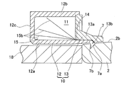
- the grease tank 10 is an annular part having a hollow grease reservoir 11 formed therein, and includes a grease tank body 12 and a grease tank tip member 13.
- the grease tank body 12 connects the inner peripheral wall portion 12a along the axial direction, the outer peripheral wall portion 12b parallel to the inner peripheral wall portion 12a, and the bearing back side of the inner peripheral wall portion 12a and the outer peripheral wall portion 12b. It consists of a back wall 12c.
- the grease tank tip member 13 is provided in a state of being fitted between the inner peripheral wall portion 12a and the outer peripheral wall portion 12b so as to close the bearing rear side opening of the grease tank main body 12.
- the inner peripheral portion of the grease tank tip member 13 is a cylindrical portion 13a extending to the bearing side.
- the inner diameter surface of the proximal end portion of the cylindrical portion 13a and the bearing side end of the inner peripheral wall portion 12a of the grease tank main body 12 are provided.
- a medium insertion clearance 14 is formed between the outer diameter surface of each part.
- the size of the medium insertion clearance 14 is such that a base oil moving medium 15 described later can be inserted.
- the cylindrical portion 13a of the grease tank tip member 13 protrudes toward the axial center side of the bearing from the medium insertion clearance 14, and covers the slope portion 2b of the inner ring 2 via the clearance ⁇ 1.
- a convex portion 13b that protrudes toward the inner peripheral side is formed at the tip of the cylindrical portion 13a.
- a side surface of the convex portion 13b facing the medium insertion clearance 14 is a tapered surface 13c having a larger diameter toward the medium insertion clearance 14 side.
- the inner diameter surface of the cylindrical portion 13a that protrudes further toward the axial center side of the bearing than the medium insertion clearance 14 serves as the outer diameter of the inner ring 2 at the tip of the base oil moving medium 15 that will be described later. It is made into the shape guided so that it may contact the slope 7a of the V-shaped circumferential groove 7 in a surface.
- the base oil moving medium 15 extracts base oil from grease and moves the base oil by capillary action, and is made of, for example, Japanese paper, cloth, leather, felt, or the like.
- Japanese paper means paper made of plant materials such as hemp, zozo and mitsumata.
- the cloth may be woven or non-woven. It is desirable that the end of the base oil moving medium 15 in the grease reservoir 11 extends to the vicinity of the back wall 12c of the grease tank body 12.
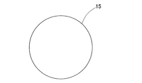
- the base oil moving medium 15 may be cylindrical and provided over the entire circumference as shown in FIG. 3, or a plurality of base oil moving media 15a having an arbitrary circumferential width as shown in FIG. May be distributed over the entire circumference. In the latter case, the circumferential length of the entire base oil moving medium 15 can be adjusted, and the amount of base oil extracted thereby can be adjusted.
- Grease tank 10 is made of steel or resin. In either case, it can be easily formed by machining. Moreover, when it is resin, it can shape
- the grease tank 10 is assembled adjacent to the rolling bearing 1 so that the bearing-side surface of the grease tank tip member 13 contacts the end surface of the outer ring 3 on the bearing back side.
- the portion of the base oil moving medium 15 that protrudes from the grease reservoir 11 abuts on the tapered surface 13c of the cylindrical portion 13a and changes its direction to the inner diameter side, and its tip is in light contact with the inclined surface 7a of the circumferential groove 7.
- the slope portion 2b of the inner ring 2 and the convex portion 13b of the grease tank tip member 13 are opposed to each other via a gap ⁇ 1.
- An O-ring 16 is provided between the bearing side end surface of the outer peripheral wall portion 12 b of the grease reservoir main body 12 and the end surface of the outer ring 3 on the bearing back side.
- the outer ring spacer 17 is fitted to the outer periphery of the grease tank 10, and the step surface 17 a of the outer ring spacer 17 is engaged with the bearing rear side end of the outer peripheral wall portion 12 b of the grease reservoir main body 12. To do. Thereby, the axial position of the grease tank 10 is restrained.
- the inner ring 2 is positioned by an inner ring spacer 18.
- the outer ring spacer 17 and the inner ring spacer 18 are made of steel.
- FIG. 5 shows an example of a spindle apparatus that employs the rolling bearing lubrication structure shown in FIGS.
- This spindle device is for a machine tool.
- a tool or workpiece chuck (not shown) is attached to one end 20a of the spindle 20, and a drive source such as a motor is connected to a rotation transmission mechanism (the other end 20b). (Not shown).
- the main shaft 20 is rotatably supported by a pair of rolling bearings 1 separated in the axial direction. In the example of the figure, the pair of rolling bearings 1 are arranged in a back combination.
- the inner ring 2 of each rolling bearing 1 is fitted to the outer diameter surface of the main shaft 20, and the outer ring 3 is fitted to the inner diameter surface of the bearing box 21.
- inner and outer rings 2 and 3 are positioned by an inner ring spacer 18 and an outer ring spacer 17, respectively, and are fixed to a main shaft 20 and a bearing box 21 by an inner ring presser spacer 22 and an outer ring presser cover 23, respectively. Further, a grease tank 10 is disposed on the back side of each rolling bearing 1.
- the operation of the lubricating structure having the above configuration will be described.
- grease is sealed in the rolling bearing 1 and grease is sealed in the grease reservoir 11 of the grease tank 10.
- the lubrication of the bearing is performed by using the initially charged grease and the grease base oil in the grease tank 10 by extracting and moving the capillarity of the base oil moving medium 15. Specifically, the grease base oil extracted by the base oil moving medium 15 is moved to the outside of the grease reservoir 11 and adheres to the slope 7 a of the circumferential groove 7 of the inner ring 2.
- the base oil adhering to the inclined surface 7a moves to the inclined surface portion 2b of the inner ring 2 due to the surface tension of the base oil and the centrifugal force accompanying the rotation of the inner ring 2, and further toward the inside of the bearing while adhering to the inclined surface portion 2b.
- the slope 7a and the slope 2b are connected to a smooth curve, the base oil moves smoothly from the slope 7a to the slope 2b.
- the clearance ⁇ 1 between the slope portion 2b of the inner ring 2 and the convex portion 13b of the grease tank tip member 13 is small, and the pumping action accompanying the rotation of the inner ring 2 facilitates the movement of the base oil along the slope portion 2b.
- the base oil that has reached the boundary edge portion with the rolling surface 2a in the slope portion 2b scatters to the outer diameter side by centrifugal force, adheres to the surface of the rolling element 4 and the inner surface of the pocket 5a of the cage 5, and lubricates. Used as oil.
- the oil adhering to the slope portion 2 b of the inner ring 2 and the oil supplied from the grease in the grease reservoir 11 through the base oil moving medium 15 are temporarily held in the circumferential groove 7. .
- the inner ring 2 rotates, so that the oil held in the circumferential groove 7 is used again as the lubricating oil. For this reason, it can always lubricate with abundant lubricating oil.
- the grease is contained in the grease reservoir 11, so that the reliability of lubrication is high and the life of the bearing can be extended.
- the grease tank 10 can be arranged on the rear side of each pair of rolling bearings 1. According to this configuration, it is not necessary to provide a lubricating component on the front side of the rolling bearing 1. Therefore, the design from which the distance from the rolling bearing 1 to the one end part 20a which is the tool attachment end of the main shaft 20 becomes the shortest can be performed. If the distance from the rolling bearing 1 to the one end portion 20a of the main shaft 20 is short, the moment stiffness against an external force load acting on the tool can be increased. However, when moment rigidity is not required, the grease tank 10 may be disposed on the front side of the rolling bearing 1.
- the base oil of grease sealed in the grease reservoir 11 of the grease tank 10 is used as the lubricating oil, an oil tank and piping are not required outside. There is no need for the bearing box 21 to be processed with high accuracy such as an oil introduction hole. Therefore, the configuration is simple and the device can be manufactured at a low cost. In addition, since a large amount of oil is not used and driving power for lubrication is not required, it is preferable from the viewpoint of energy saving and resource saving. Furthermore, because of grease lubrication, no maintenance is required.
- FIG. 6 and 7 show a second embodiment of the present invention in which the base oil moving medium 15 is different.
- the portion of the base oil moving medium 15 that is inserted into the grease reservoir 11 is branched into a plurality of branch portions 15b that are separated from each other in the circumferential direction.
- the branch portions 15b can be dispersed and arranged in a wide range of the grease reservoir 11. The base oil can be efficiently extracted from the entire area of the grease reservoir 11.
- FIG. 8 shows a third embodiment in which the circumferential groove 7 is not provided in the slope portion 2 b of the inner ring 2.
- the tip of the portion of the base oil moving medium 15 that protrudes from the grease reservoir 11 is in contact with the slope portion 2b.
- the base oil extracted from the grease in the grease reservoir 11 by the base oil moving medium 15 adheres to the slope portion 2 b of the inner ring 2.
- the subsequent operation is the same as that in the above embodiment.
- the circumferential groove 7 is provided because the action of retaining oil in the circumferential groove 7 is obtained when the operation is stopped as described above, but even if the circumferential groove 7 is not provided, Lubrication reliability is high and bearing life can be extended. If the circumferential groove 7 is not provided, there is an advantage that the inner ring 2 can be easily processed and the inner ring 2 can be manufactured at low cost.
- FIG. 9 shows a fourth embodiment in which a step portion 19 is provided in the inner ring 2 instead of the circumferential groove 7.
- the step portion 19 includes a step surface 19a that is a surface orthogonal to the bearing center line O following the edge of the slope portion 2b, and a cylindrical surface 19b that extends axially outward from the inner diameter end of the step surface 19a. .
- the step surface 19a and the slope portion 2b are connected to a smooth curve. In a broad sense, the step surface 19a is a part of the slope portion 2b.
- the tip of the portion of the base oil moving medium 15 that protrudes from the grease reservoir 11 is in contact with the step surface 19a.
- the base oil extracted from the grease in the grease reservoir 11 by the base oil moving medium 15 first adheres to the step surface 19a, and is transmitted from the step surface 19a to the slope portion 2b to be supplied into the bearing.
- the lubricating structure of the present invention can also be applied to the case where the rolling bearing 1 is a cylindrical roller bearing as in the fifth embodiment shown in FIG.
- both sides of the rolling surface 2a on the outer diameter surface of the inner ring 2 are the slope portions 2b, and the circumferential grooves 7 are formed in each slope portion 2b.
- Grease tanks 10 are disposed on both sides of the rolling bearing 1, and the tip of the base oil moving medium 15 provided in each grease tank 10 is in contact with the inclined surface 7 a on the rolling surface 2 a side of each circumferential groove 7.
- the grease tank 10 is provided on both sides of the rolling bearing 1, but the grease tank 10 may be provided on only one side as long as the lubrication conditions are satisfied.
- the lubrication structure of the rolling bearing that supports the machine tool spindle has been described.
- the lubrication structure of the present invention is a bearing other than the machine tool spindle, for example, a bearing used for a motor or a general work machine. It can also be applied to.
- the rolling bearing according to this embodiment includes an inner ring 2, an outer ring 3, a plurality of rolling elements 4, and a cage 5, as in the first embodiment.
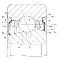
- the grease tank 10 in which the hollow grease reservoir 11 is formed is not provided. Both ends of the bearing space between the inner and outer rings 2 and 3 are closed by sealing devices 6 and 6, grease is sealed inside the bearings, and a base oil moving medium 15A which will be described in detail later on the inner wall surfaces of the sealing devices 6 and 6.
- a base oil moving medium 15A which will be described in detail later on the inner wall surfaces of the sealing devices 6 and 6.
- an angular ball bearing is applied to the rolling bearing, which is an inner ring rotating type.
- the rolling bearing is not limited to the angular ball bearing.
- a deep groove ball bearing, a cylindrical roller bearing, or a tapered roller bearing can be applied.
- the outer ring 3 is provided with shields made of steel plates as sealing devices 6 on both sides, and this bearing is a sealed rolling bearing.
- Sealing device fixing grooves 3b that are recessed radially outward from the inner diameter of the outer ring are formed at both ends of the inner diameter surface of the outer ring 3.
- the outer diameter surfaces 2b on both sides of the inner ring 2 are provided with slopes (to be described later) that become larger in diameter as they approach the rolling surface 2a side from the end surface side and contact the inner peripheral edge portion 15Aa of the base oil moving medium 15A.
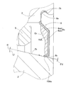
- the radially outer base end portion 6a of the sealing device 6 is fixed to the sealing device fixing groove 3b.
- a radially inner tip portion 6b of the sealing device 6 is formed in a substantially L-shaped cross section toward the inside of the bearing toward the tip, and is predetermined so as not to contact the slope portion 2b of the outer diameter surface of the inner ring 2.
- a small distance gap ⁇ 2 is formed.
- the gap ⁇ 2 is set to a size that provides a sealing effect.
- the sealing device 6 is not in contact with the inclined surface portion 2b of the outer diameter surface of the inner ring 2.
- the intermediate part 6c connected to the base end part 6a in the sealing device 6 includes an inclined part 6ca and a standing plate part 6cb. That is, in the sealing device 6, the inclined portion 6 ca that inclines toward the bearing outer side as it goes inward in the radial direction is connected to the inner peripheral edge portion of the base end portion 6 a, and the upright plate portion 6 cb is connected to the inner peripheral edge portion of the inclined portion 6 ca.
- the upright plate portion 6cb is provided along a plane perpendicular to the bearing axial direction, and the tip end portion 6b is connected to the inner peripheral edge of the upright plate portion 6cb.
- An annular base oil moving medium 15 ⁇ / b> A made of a material that causes capillary action is provided on the inner wall surface of the sealing device 6.
- the base oil moving medium 15A is fixed over the inner peripheral portion of the base end portion 6a, the inclined portion 6ca, and the upright plate portion 6cb.
- the entire circumference of the inner peripheral edge 15 ⁇ / b> Aa of the base oil moving medium 15 ⁇ / b> A is brought into contact with the inclined surface 2 b of the outer diameter surface of the inner ring 2.
- the inner peripheral edge 15Aa of the base oil moving medium 15A is inclined to the bearing inner side as it goes to the tip, and is held by the tip 6b having a substantially L-shaped cross section.
- the material of the base oil moving medium 15A is the same as that of the above embodiment.
- a part of the grease sealed in the bearing space between the inner and outer rings 2 and 3 is attached to the inner wall surface of the sealing device 6.
- the grease adhered to the inner wall surface is referred to as “sealing device adhesion grease Gr”.
- the sealing device adhesion grease Gr is adhered to the inner wall surface of the sealing device 6 by the operation of the bearing.
- the sealing device adhesion grease Gr is adhered to the inner wall surface of the sealing device 6 when the bearing is assembled. You may let them.
- the slope is provided on the slope portion 2 b of the outer diameter surface of the inner ring 2.
- the entire slope portion 2b of the outer diameter surface is a slope, but a part of the outer diameter surface of the inner ring 2 may be a slope. Since the centrifugal force acting on the grease varies depending on the rotational speed, it is preferable that the inclination angle of the outer diameter surface of the inner ring 2 with respect to the axial direction L1 is set corresponding to the allowable rotational speed or the used rotational speed of the bearing. At that time, when the inclination angle of the outer diameter surface of the inner ring 2 is ⁇ , the pitch circle diameter of the rolling element is dm (mm) (FIG.
- a value obtained by multiplying the pitch circle diameter dm (mm) of the rolling element by the rotational speed n (min-1) is referred to as a dmn value.
- the grease existing on the rolling surface by the operation of the bearing is stepped on the rolling element 3, a part of the grease is scraped to the end of the rolling surface, a part is scattered, and the sealing device 6 provided at both ends of the bearing. It adheres to the inner wall surface of.
- the base oil moving medium 15A is provided on the inner wall surface of the sealing device 6, and the inner peripheral edge portion 15Aa of the base oil moving medium 15A is brought into contact with the inclined surface portion 2b of the outer diameter surface of the inner ring 2.
- the unit moves from the grease attached to the sealing device Gr to the slope portion 2b of the outer diameter surface of the inner ring 2.
- the amount of base oil movement per hour can be increased.
- the rolling bearing at high speed and at medium and high loads.
- the base oil moving medium 15A is fixed over the inner peripheral portion of the base end portion 6a, the inclined portion 6ca, and the upright plate portion 6cb.
- the inner peripheral edge 15Aa of the base oil moving medium 15A is inclined to the inside of the bearing toward the tip, and is held by the tip 9 having a substantially L-shaped cross section. 6ca, the standing plate portion 6ca, and the tip portion 6b can be stably attached in an annular groove surrounded by a substantially concave shape in cross section. Without providing a complicated structure, only the base oil can be gradually supplied from the sealing device-attached grease Gr stably attached in the annular groove. Since the sealing device 6 is not in contact with the inclined surface portion 2b of the outer diameter surface of the inner ring 2, this rolling bearing is used for, for example, a machine tool bearing or a general industrial machine motor in which low torque is desired from the viewpoint of low heat generation and energy saving. It can be suitably used as a bearing or the like.
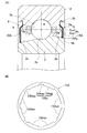
- FIGS. 13A and 13B a part of the inner peripheral edge 15 ⁇ / b> Aa of the base oil moving medium 15 ⁇ / b> A may be brought into contact with the slope 2 b of the outer diameter surface of the inner ring 2.
- FIG. 13B is a side view showing only the inner peripheral edge 15Aa of the base oil moving medium 15A of the rolling bearing of FIG. 13A from the axial direction.
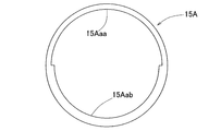
- the inner peripheral edge portion 15Aa of the base oil moving medium 15A is provided with a recessed portion 15Aaa that is recessed radially outward at regular intervals in the circumferential direction.
- the inner peripheral edge portion 15Aa is provided with a concave shape portion 15Aaa and a convex shape portion 15Aab adjacent to each other in the circumferential direction, and among these, a plurality (eight in this example) of the convex shape portions 15Aab are provided on the outer diameter surface of the inner ring 2. It is made to contact with the slope part 2b.
- the base oil movement per unit time moving from the sealing device adhesion grease Gr to the slope portion 2b of the outer diameter surface of the inner ring 2 is achieved. The amount decreases. Thereby, base oil can be utilized for a long time.
- FIG. 14 is a side view showing only the inner peripheral edge 15Aa of the base oil moving medium 15A of the rolling bearing according to the eighth embodiment from the axial direction.
- an intermediate portion in the range of 180 degrees in the circumferential direction may be a concave shape portion 15Aaa, and the remaining intermediate portion may be a convex shape portion 15Aab.
- the base oil movement amount per unit time that moves from the sealing device-attached grease Gr to the slope portion 2b of the inner ring outer diameter surface is reduced. It can be used for a longer time.
- the outer diameter surface on one side of the inner ring 2 may be a flat surface parallel to the axial direction as in the ninth embodiment shown in FIG. good.
- the base oil necessary for lubrication in the sealer-attached grease Gr can be adhered to the outer diameter surface of the inner ring 2 via the base oil moving medium 15A by the capillary phenomenon, thereby contributing to lubrication.
- a seal formed by reinforcing an elastic body 61 with a cored bar 62 may be applied as the sealing device 6.
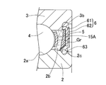
- an annular seal groove 2 c that contacts the seal lip 63 is formed on the inclined surface portion 2 b of the outer diameter surface of the inner ring 2, and a contact seal is used as a seal.
- a deep groove ball bearing is applied as the rolling bearing, and an iron plate corrugated cage is applied as the cage 5.
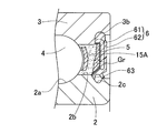
- a seal may be applied as the sealing device 6, and the inclined surface 2 b of the outer diameter surface of the inner ring 2 may be a flat surface parallel to the axial direction as in FIG. 15.
- the sealing device 6 may be a contact type as in the tenth and eleventh embodiments shown in FIGS. .
- the sealing device 6 and the base oil moving medium 15A may be provided only on one side of the bearing.
- a slope may be provided only on the inner ring outer diameter surface on one side where the base oil moving medium 15A is provided.
- a contact seal is used in FIGS. 16 and 17, a non-contact seal can be applied.
- the rolling bearing of each embodiment can be configured without a cage.
- a rolling bearing according to aspect 1 is a rolling bearing including an inner and outer ring, a plurality of rolling elements interposed between the inner and outer rings, and a sealing device that is provided in the outer ring and closes a bearing space between the inner and outer rings.
- An annular base oil moving medium made of a material that causes capillary action is provided on the inner wall surface of the sealing device, and the inner peripheral edge of the base oil moving medium is brought into contact with the outer diameter surface of the inner ring. It is a thing.
Landscapes
- Engineering & Computer Science (AREA)
- General Engineering & Computer Science (AREA)
- Mechanical Engineering (AREA)
- Rolling Contact Bearings (AREA)
Abstract
Description
グリースタンクに設けた媒体挿通すきまに基油移動媒体を挿通することにより、グリース溜り内からのグリースまたは基油の漏出を防ぎつつ、グリース中の基油を、基油移動媒体を伝わらせてグリース溜り外へ導き出すことができる。グリースタンクに筒状部を形成し、その内径面を、基油移動媒体のグリース溜り外の部分を先端が斜面部に接触させるように案内する形状とすることにより、基油移動媒体の一端を確実に斜面部に接触させることができる。
斜面部に円周溝が設けてあると、運転停止時に、内輪の斜面部に付着している基油と、基油移動媒体を伝ってグリース溜りのグリースから抽出される基油とを円周溝に一時的に保持させられる。始動時に円周溝に保持されていた油を再度潤滑油として利用することができ、常に潤沢な潤滑油で潤滑を行うことができる。円周溝を断面V状とすることで、基油移動媒体の一端から円周溝の転走面側の斜面に吐出される基油が、内輪外径面の斜面部へ移動しやすい。円周溝の斜面の斜度は、内輪の実用回転速度により決定される。具体的には、高速度になるほど、斜度を大きくする。
この場合、基油移動媒体により、グリース溜り内のグリースから抽出された基油が内輪の段面に付着する。段面に付着した基油は、段面から斜面部へ移り、斜面部に沿って軸受内部方向へ移動して、潤滑油として利用される。このように斜面部に段部を設けることによっても、前記同様、運転停止時に段部に油を一時的に保持させて、常に潤沢な潤滑油で潤滑を行うことができる。
α≧{0.056・dm°n・10-4}-2
の関係が成り立つようにするのが良い。
内輪外径面の斜面部の角度の好ましい値は、軸受のdm°n値によって異なる。試験の結果、斜面部の角度αは上記式で表わされる値とするのが良いことが分かった。なお、dm°n値はラジアル軸受の使用条件の高速の程度を示す数値であり、軸受内径と外径の平均値dmと許容回転数nの積で表される。
いずれの材料も、グリースから基油を抽出して含有する性質と、含有した基油を毛細管現象により移動させる性質とを有する。そのため、グリース溜りのグリースから基油を抽出して内輪外径面の斜面部へ導く基油移動媒体の材料として好適である。
基油移動媒体が斜面部との接触部分の円周方向長さを調整可能であれば、その円周方向長さを調整することにより、内輪斜面部への付着油量を調整できる。
基油移動媒体のグリース溜り部内の部分が上記のように分岐していれば、各分岐部分をグリース溜りの広い範囲に分散して配置することができ、グリース溜りの全域から基油を効率良く抽出できる。
この構成によると、グリースの基油を移動させる基油移動媒体を密封装置の内壁面に設け、前記基油移動媒体の内周縁部を、前記内輪の外径面に、端面側から転走面(軌道面)側に近づく程大径となるように設けた斜面部に接触させているので、前記密封装置の内壁面に付着した密封装置付着グリースのうち潤滑に必要な基油のみを、毛細管現象によって、基油移動媒体を介して前記斜面部に付着させる。内輪が回転すると、前記斜面部に付着した基油を遠心力、表面張力により潤滑に寄与させ得る。これにより、同量のグリースを封入した従来の密封装置付き転がり軸受より、長寿命化を図ることが可能となる。
上記2つの作用、すなわち毛細管現象の作用および付着流れの作用により、密封装置付着グリースが軸受の潤滑に寄与する。軸受の慣らし運転を行うと、密封装置付着グリースの基油は、毛細管現象の作用により基油移動媒体を介して前記斜面部に供給される。この内輪外径面の斜面部に供給された基油は、付着流れにより軸受の中心に移動して潤滑に寄与する。
前記内輪の外径面の斜面角度をαとし、転動体のピッチ円直径をdm(mm)とし、回転速度をn(min-1)としたとき、斜面角度αが次式で与えられるものであっても良い。
α≧{0.056・dm・n・10-4}-2
この式は、斜面を持つ内径70mmと100mm軸受の擬似内輪を用いて実施した実験結果を基にしている。内輪の斜面部(角度変更実施)にエアオイルを利用して油を付着させ,付着流れの有無を目視にて観察する方法で実施した。斜面での付着流れの考え方として、斜面に油が付着すればエアオイルの油,グリースの基油の差はないと考える。
前記斜面部に対し密封装置を非接触としても良い。例えば、低発熱・省エネルギーの観点から低トルクが望まれる工作機械用軸受、一般産業機械モータ用軸受等では、前記密封装置を非接触とすると良い。
前記斜面部に対し密封装置を接触するものとしても良い。例えば、防塵・防水性を重視する鉄道車両用軸受、自動車用軸受、風車用軸受等では、前記密封装置を接触とすると良い。
α≧{0.056・dm・n・10-4}-2の式で表される。この式は、試験の結果より求められたものである。ただし、dmは前記転動体のピッチ円直径(mm)、nは回転速度(min-1)である。
組立て時に、転がり軸受1の内部にグリースを封入すると共に、グリースタンク10のグリース溜り11内にグリースを封入しておく。軸受の潤滑は、初期封入したグリースと、グリースタンク10内のグリース基油を、基油移動媒体15の持つ毛細管現象による抽出と移動作用を利用して行う。具体的には、基油移動媒体15で抽出されたグリース基油がグリース溜り11外の方へ移動させられて、内輪2の円周溝7の斜面7aに付着する。斜面7aに付着した基油は、基油の持つ表面張力と、内輪2の回転に伴う遠心力とにより、内輪2の斜面部2bへ移動し、さらに斜面部2bに付着しながら軸受内部方向へ移動する。斜面7aと斜面部2bとは滑らかな曲線に繋がっているので、斜面7aから斜面部2bへの基油の移動は円滑に行われる。また、内輪2の斜面部2bとグリースタンク先端部材13の凸部13bとの間のすきまδ1は小さく、内輪2の回転に伴うポンピング作用により、斜面部2bに沿う基油移動が促進されると共に、軸受内からのグリース洩れを防止するシール効果も期待できる。斜面部2bにおける転走面2aとの境界エッジ部に達した基油は、遠心力により外径側へ飛散し、転動体4の表面および保持器5のポケット5aの内面に付着して、潤滑油として利用される。
この実施形態に係る転がり軸受は、図11に示すように、前記第1実施形態と同様、内輪2、外輪3、複数の転動体4、保持器5を備えているが、前記第1実施形態にような内部に中空状のグリース溜り11が形成されたグリースタンク10を備えていない。内外輪2,3間の軸受空間の両端は密封装置6、6で塞がれ、軸受内部にグリースが封入され、この密封装置6、6の内壁面に、後で詳しく述べる基油移動媒体15Aが設けられた点で第1実施形態と異なる。なお、この例の転がり軸受はアンギュラ玉軸受が適用され、内輪回転形とされる。但し、転がり軸受はアンギュラ玉軸受に限定されるものではない。転がり軸受として、例えば、深溝玉軸受、円筒ころ軸受、または円錐ころ軸受を適用することも可能である。
図11、図12に示すように、外輪3には、密封装置6として鋼板から成るシールドを両側に取付け、この軸受を密封形の転がり軸受としている。外輪3の内径面の両端部には、この外輪内径よりも半径方向外方に凹む密封装置固定溝3bが形成されている。内輪2の両側の外径面2bに、端面側から転走面2a側に近づく程大径となり、基油移動媒体15Aの内周縁部15Aaが接触する斜面(後述する)が設けられている。
図12に示すように、密封装置6の半径方向外方の基端部6aは前記密封装置固定溝3bに固定される。この密封装置6の半径方向内方の先端部6bは、先端に向かうに従って軸受内側に向かう断面略L字形状に形成されると共に、内輪2の外径面の斜面部2bに接触しないように所定小距離隙間δ2が形成されている。この隙間δ2はシール効果が得られる程度の大きさに定められている。このように本例では、内輪2の外径面の斜面部2bに対し密封装置6を非接触としている。
また、内外輪2,3間の軸受空間に封入するグリースの一部を、密封装置6の内壁面に付着させている。この内壁面に付着させたグリースを「密封装置付着グリースGr」と称す。この例では、密封装置付着グリースGrを軸受の運転により密封装置6の内壁面に付着させているが、後述するように、軸受組立時において密封装置付着グリースGrを密封装置6の内壁面に付着させても良い。
回転速度によってグリースに働く遠心力が異なるため、内輪2の外径面の軸方向L1に対する傾斜角度は、軸受の許容回転数または使用回転数に対応して設定することが好ましい。その際、内輪2の外径面の傾斜角度をαとし、転動体のピッチ円直径をdm(mm)(図11)とし、回転速度をn(min-1)としたとき、次式を用いて傾斜角度αを与える
と、内輪2の斜面に付着した基油が転走面2aに移動し潤滑に寄与するため、より好適である。
ここで、転動体のピッチ円直径dm(mm)に回転速度n(min-1)を乗じた値は、dmn値と
称される。
このように2つの作用すなわち毛細管現象の作用および前記付着流れの作用により、密着装置付着グリースGrが軸受の潤滑に寄与する。
密封装置6の内壁面のうち、基端部6aの内周部分、傾斜部6ca、および立板部6cbにわたって基油移動媒体15Aが固着されている。さらに基油移動媒体15Aの内周縁部15Aaは、先端に向かうに従って軸受内側に傾斜し、且つ、断面略L字形状の先端部9に保持されているため、密封装置付着グリースGrを、傾斜部6ca、立板部6ca、および先端部6bで断面略凹形状に囲まれた環状凹溝内に安定して付着させることができる。複雑な構造を設けることなく、前記環状凹溝内に安定して付着させた密封装置付着グリースGrから基油のみを徐々に供給することが可能となる。
内輪2の外径面の斜面部2bに対し密封装置6を非接触としたため、この転がり軸受を、例えば、低発熱・省エネルギーの観点から低トルクが望まれる工作機械用軸受、一般産業機械モータ用軸受等として好適に用いることができる。
基油移動媒体15Aにおける内周縁部15Aaには、円周方向一定間隔おきに半径方向外方に凹む凹形状部15Aaaが設けられている。内周縁部15Aaは凹形状部15Aaaと凸形状部15Aabとが円周方向に隣接して設けられ、これらのうち複数(この例では8つ)の凸形状部15Aabを、内輪2の外径面の斜面部2bに接触させている。このように基油移動媒体15Aにおける、内輪外径面との接触部を限定することで、密封装置付着グリースGrから内輪2の外径面の斜面部2bに移動する単位時間あたりの基油移動量が減少する。これにより、基油をより長時間利用することができる。
図17に示す第11実施形態のように、密封装置6としてシールを適用し、内輪2の外径面の斜面部2bを図15と同様に軸方向に平行な平坦面としても良い。
例えば、防塵・防水性を重視する鉄道車両用軸受、自動車用軸受、風車用軸受等では、図16、図17に示す第10、第11実施形態のように密封装置6を接触式とすると良い。
[態様1]
態様1にかかる転がり軸受は、内外輪と、これら内外輪間に介在する複数の転動体と、前記外輪に設けられ内外輪間の軸受空間を塞ぐ密封装置とを備えた転がり軸受であって、前記密封装置の内壁面に、毛細管現象を生じる材料から成りグリースの基油を移動させる円環状の基油移動媒体を設け、この基油移動媒体の内周縁部を内輪の外径面に接触させたものである。
2…内輪
2a…転走面
2b…斜面部
3…外輪
6…密封装置(シール)
7…円周溝
7a…傾斜面(側面)
8…密封装置
10…グリースタンク
11…グリース溜り
13a…筒状部
14…媒体挿通すきま
15、15A…基油移動媒体
15b…分岐部
19…段部
19a…段面
20…主軸
O…軸受中心線
Claims (15)
- 内外輪と、これら内外輪間に介在する複数の転動体とを有し、回転輪である前記内輪の外径面における転走面の側方に斜面部を設けると共に、転がり軸受の外輪に隣接して、内部にグリース溜りが形成されたグリースタンクを配置し、このグリースタンクのグリース溜り内に、グリース中の基油を毛細管現象により移動させる基油移動媒体を設け、この基油移動媒体の一端を前記斜面部に接触させ、前記グリース溜りに封入されているグリース中の基油が前記基油移動媒体を伝って前記斜面部に付着し、その斜面部に付着した基油を、基油の表面張力と前記内輪の回転により生じる前記斜面部に沿う基油の付着流れとを利用して軸受内へ供給するようにした転がり軸受の潤滑構造。
- 請求項1において、前記グリースタンクは、前記グリース溜りと外部とを連通する媒体挿通すきまを有し、この媒体挿通すきまに前記基油移動媒体を挿通したものであり、前記グリースタンクの外殻における前記媒体挿通すきまの外径側部分を前記内輪の前記斜面部にすきま部を介して被さる筒状部として形成し、この筒状部における前記媒体挿通すきまよりも軸受の軸方向中心側へ突出した部分の内径面を、前記基油移動媒体のグリース溜り外の部分を先端が前記斜面部に接触させるように案内する形状とした転がり軸受の潤滑構造。
- 請求項1において、前記斜面部に断面V状の円周溝を設け、この円周溝の前記転走面側の斜面に前記基油移動媒体の一端を接触させた転がり軸受の潤滑構造。
- 請求項1において、前記斜面部に前記転走面から遠い側が小径となる段部を設け、この段部の段面に前記基油移動媒体の一端を接触させた転がり軸受の潤滑構造。
- 請求項1において、軸受中心線に対する前記斜面部の角度をα(°)、転動体のピッチ円直径をdm(mm)、回転速度をn(min-1)とした場合、
α≧{0.056・dm・n・10-4}-2
の関係が成り立つ転がり軸受の潤滑構造。 - 請求項1において、前記基油移動媒体の材料を毛細管現象が生じる和紙、不織布を含む織布、および皮革の少なくともいずれか1つとした転がり軸受の潤滑構造。
- 請求項1において、前記基油移動媒体は、前記斜面部との接触部分の円周方向長さを調整可能に前記グリースタンクに設けた転がり軸受の潤滑構造。
- 請求項1において、前記基油移動媒体における前記グリース溜り内の部分を、互いに円周方向に離れた複数の分岐部に分岐させた転がり軸受の潤滑構造。
- 内外輪と、これら内外輪間に介在する複数の転動体と、前記外輪に設けられ内外輪間の軸受空間を塞ぐ密封装置とを有し、前記内輪の外径面に、端面側から転走面側に近づく程大径となる斜面部を設けた転がり軸受であって、
前記密封装置の内壁面に、毛細管現象を生じる材料から成りグリースの基油を移動させる円環状の基油移動媒体を設け、この基油移動媒体の内周縁部の全周または一部を回転輪である前記内輪の外径面の斜面部に接触させた転がり軸受。 - 請求項9において、前記内輪における外径面の斜面の斜面角度を、軸受の許容回転速度または使用回転速度で回転させた場合に、基油が遠心力で前記斜面を転走面側へ流れる角度とした転がり軸受。
- 請求項9において、前記基油移動媒体および内輪の外径面の斜面を、軸受の片側のみまたは両側に設けた転がり軸受。
- 請求項9において、前記内輪の外径面の斜面角度をαとし、転動体のピッチ円直径をdm(mm)とし、回転速度をn(min-1)としたとき、斜面角度αが次式で与えられる転がり軸受。
α≧{0.056・dm・n・10-4}-2 - 請求項9において、前記基油移動媒体の材料を毛細管現象が生じる和紙、布および皮革の少なくともいずれか1つとした転がり軸受。
- 請求項9において、前記内輪の外径面に対し密封装置を非接触とした転がり軸受。
- 請求項9において、前記内輪の外径面に対し密封装置を接触するものとした転がり軸受。
Priority Applications (2)
| Application Number | Priority Date | Filing Date | Title |
|---|---|---|---|
| US13/579,465 US20120301065A1 (en) | 2010-02-17 | 2011-02-10 | Rolling bearing lubrication structure and rolling bearing |
| CN201180009976XA CN102762880A (zh) | 2010-02-17 | 2011-02-10 | 滚动轴承的润滑结构和滚动轴承 |
Applications Claiming Priority (4)
| Application Number | Priority Date | Filing Date | Title |
|---|---|---|---|
| JP2010-032258 | 2010-02-17 | ||
| JP2010032258A JP2011169362A (ja) | 2010-02-17 | 2010-02-17 | 転がり軸受の潤滑構造 |
| JP2010074325A JP2011208662A (ja) | 2010-03-29 | 2010-03-29 | 転がり軸受 |
| JP2010-074325 | 2010-03-29 |
Publications (1)
| Publication Number | Publication Date |
|---|---|
| WO2011102303A1 true WO2011102303A1 (ja) | 2011-08-25 |
Family
ID=44482889
Family Applications (1)
| Application Number | Title | Priority Date | Filing Date |
|---|---|---|---|
| PCT/JP2011/052943 Ceased WO2011102303A1 (ja) | 2010-02-17 | 2011-02-10 | 転がり軸受の潤滑構造および転がり軸受 |
Country Status (3)
| Country | Link |
|---|---|
| US (1) | US20120301065A1 (ja) |
| CN (1) | CN102762880A (ja) |
| WO (1) | WO2011102303A1 (ja) |
Cited By (2)
| Publication number | Priority date | Publication date | Assignee | Title |
|---|---|---|---|---|
| JP2015034587A (ja) * | 2013-08-08 | 2015-02-19 | 株式会社ジェイテクト | 転がり軸受装置 |
| JP2016121735A (ja) * | 2014-12-24 | 2016-07-07 | Ntn株式会社 | 転がり軸受用保持器および転がり軸受 |
Families Citing this family (20)
| Publication number | Priority date | Publication date | Assignee | Title |
|---|---|---|---|---|
| KR20140060318A (ko) * | 2011-09-13 | 2014-05-19 | 엔티엔 가부시키가이샤 | 베어링 장치 |
| JP6184096B2 (ja) * | 2012-12-27 | 2017-08-23 | ミネベアミツミ株式会社 | 転がり軸受、スロットルバルブ装置及びアンチロックブレーキ装置 |
| JP6136279B2 (ja) * | 2013-01-15 | 2017-05-31 | 株式会社ジェイテクト | 転がり軸受装置 |
| JP6331062B2 (ja) | 2013-03-21 | 2018-05-30 | 株式会社ジェイテクト | 転がり軸受装置 |
| EP3017206B1 (en) * | 2013-07-03 | 2017-09-06 | Aktiebolaget SKF | Bearing assembly with lubrication cartridge |
| WO2015000509A1 (en) * | 2013-07-03 | 2015-01-08 | Aktiebolaget Skf | Bearing assembly with lubrication cartridge |
| JP6495700B2 (ja) * | 2015-03-17 | 2019-04-03 | Ntn株式会社 | 軸受装置および機械装置 |
| JP6523728B2 (ja) * | 2015-03-24 | 2019-06-05 | Ntn株式会社 | 軸受装置 |
| JP6582566B2 (ja) * | 2015-06-03 | 2019-10-02 | 株式会社ジェイテクト | 転がり軸受 |
| US9958005B2 (en) * | 2015-10-13 | 2018-05-01 | Shimadzu Corporation | Oil-lubricated bearing device and vacuum pump |
| JP6957836B2 (ja) | 2016-01-26 | 2021-11-02 | 株式会社ジェイテクト | 転がり軸受 |
| DE102016206141A1 (de) * | 2016-04-13 | 2017-10-19 | Robert Bosch Gmbh | Vorrichtung mit einem Reibkontakt und Verfahren zum Betreiben einer Vorrichtung mit einem Reibkontakt |
| TWI603020B (zh) | 2016-11-04 | 2017-10-21 | 財團法人工業技術研究院 | 流體機械潤滑系統總成 |
| JP6874455B2 (ja) | 2017-03-22 | 2021-05-19 | 株式会社ジェイテクト | 転がり軸受 |
| JP6946697B2 (ja) | 2017-03-31 | 2021-10-06 | 株式会社ジェイテクト | 転がり軸受 |
| CN107489697A (zh) * | 2017-07-05 | 2017-12-19 | 徐州博丰轴承有限公司 | 一种滚动轴承 |
| JP6950430B2 (ja) | 2017-10-04 | 2021-10-13 | 株式会社ジェイテクト | 玉軸受 |
| CN111075845B (zh) * | 2020-01-08 | 2021-11-05 | 上海航天控制技术研究所 | 一种主动式补充供油装置 |
| CN113638965B (zh) * | 2021-10-13 | 2021-12-07 | 南通龙达生物新材料科技有限公司 | 一种生物质颗粒机用轴承 |
| CN116104874B (zh) * | 2023-01-13 | 2025-07-08 | 中铝西南铝板带有限公司 | 一种用于喷淋工况下的密封轴承箱 |
Citations (3)
| Publication number | Priority date | Publication date | Assignee | Title |
|---|---|---|---|---|
| JP2009162341A (ja) * | 2008-01-09 | 2009-07-23 | Ntn Corp | 転がり軸受 |
| JP2009236142A (ja) * | 2008-03-26 | 2009-10-15 | Ntn Corp | 転がり軸受の潤滑構造 |
| JP2010019268A (ja) * | 2008-07-08 | 2010-01-28 | Ntn Corp | 転がり軸受装置 |
Family Cites Families (3)
| Publication number | Priority date | Publication date | Assignee | Title |
|---|---|---|---|---|
| KR101199444B1 (ko) * | 2004-10-08 | 2012-11-09 | 엔티엔 가부시키가이샤 | 롤링 베어링 |
| JP4256391B2 (ja) * | 2006-01-05 | 2009-04-22 | Ntn株式会社 | 転がり軸受 |
| JP2008121830A (ja) * | 2006-11-14 | 2008-05-29 | Ntn Corp | オルタネータ用軸受 |
-
2011
- 2011-02-10 US US13/579,465 patent/US20120301065A1/en not_active Abandoned
- 2011-02-10 CN CN201180009976XA patent/CN102762880A/zh active Pending
- 2011-02-10 WO PCT/JP2011/052943 patent/WO2011102303A1/ja not_active Ceased
Patent Citations (3)
| Publication number | Priority date | Publication date | Assignee | Title |
|---|---|---|---|---|
| JP2009162341A (ja) * | 2008-01-09 | 2009-07-23 | Ntn Corp | 転がり軸受 |
| JP2009236142A (ja) * | 2008-03-26 | 2009-10-15 | Ntn Corp | 転がり軸受の潤滑構造 |
| JP2010019268A (ja) * | 2008-07-08 | 2010-01-28 | Ntn Corp | 転がり軸受装置 |
Cited By (2)
| Publication number | Priority date | Publication date | Assignee | Title |
|---|---|---|---|---|
| JP2015034587A (ja) * | 2013-08-08 | 2015-02-19 | 株式会社ジェイテクト | 転がり軸受装置 |
| JP2016121735A (ja) * | 2014-12-24 | 2016-07-07 | Ntn株式会社 | 転がり軸受用保持器および転がり軸受 |
Also Published As
| Publication number | Publication date |
|---|---|
| US20120301065A1 (en) | 2012-11-29 |
| CN102762880A (zh) | 2012-10-31 |
Similar Documents
| Publication | Publication Date | Title |
|---|---|---|
| CN102762880A (zh) | 滚动轴承的润滑结构和滚动轴承 | |
| RU2450176C2 (ru) | Роликовый подшипник | |
| JP5129762B2 (ja) | アンギュラ玉軸受 | |
| EP3388173B1 (en) | Spindle apparatus | |
| US8523449B2 (en) | Rolling bearing | |
| JP6481717B2 (ja) | 玉軸受、それを用いたモータ及び主軸装置 | |
| JP2011208662A (ja) | 転がり軸受 | |
| JP2008240796A (ja) | シール付きアンギュラ玉軸受及び主軸装置 | |
| JP5899933B2 (ja) | スピンドル装置 | |
| JP2007010026A (ja) | 円筒ころ軸受及び円筒ころ軸受用保持器 | |
| JP2011169362A (ja) | 転がり軸受の潤滑構造 | |
| JP5982881B2 (ja) | 玉軸受、それを用いたモータ及び主軸装置 | |
| JP6206469B2 (ja) | スピンドル装置 | |
| JP2005180629A (ja) | 転がり軸受 | |
| JP4256391B2 (ja) | 転がり軸受 | |
| JP2009162341A (ja) | 転がり軸受 | |
| JP2005221042A (ja) | 転がり軸受 | |
| JP2006226427A (ja) | 転がり軸受 | |
| CN202598074U (zh) | 复合固体润滑潜伏式润滑的摩擦件 | |
| JP2012072861A (ja) | スピンドル装置 | |
| JP2006234072A (ja) | 転がり軸受 | |
| JP2011069456A (ja) | 転がり軸受 | |
| CN202598075U (zh) | 一种复合固体润滑潜伏式润滑摩擦件 | |
| JP6354148B2 (ja) | 軸受装置及びスピンドル装置 | |
| JP2006105345A (ja) | 転がり軸受 |
Legal Events
| Date | Code | Title | Description |
|---|---|---|---|
| WWE | Wipo information: entry into national phase |
Ref document number: 201180009976.X Country of ref document: CN |
|
| 121 | Ep: the epo has been informed by wipo that ep was designated in this application |
Ref document number: 11744590 Country of ref document: EP Kind code of ref document: A1 |
|
| WWE | Wipo information: entry into national phase |
Ref document number: 13579465 Country of ref document: US |
|
| NENP | Non-entry into the national phase |
Ref country code: DE |
|
| WWE | Wipo information: entry into national phase |
Ref document number: 7204/DELNP/2012 Country of ref document: IN |
|
| 122 | Ep: pct application non-entry in european phase |
Ref document number: 11744590 Country of ref document: EP Kind code of ref document: A1 |