WO2011102070A1 - 歯科矯正用口蓋側固定装置 - Google Patents
歯科矯正用口蓋側固定装置 Download PDFInfo
- Publication number
- WO2011102070A1 WO2011102070A1 PCT/JP2011/000084 JP2011000084W WO2011102070A1 WO 2011102070 A1 WO2011102070 A1 WO 2011102070A1 JP 2011000084 W JP2011000084 W JP 2011000084W WO 2011102070 A1 WO2011102070 A1 WO 2011102070A1
- Authority
- WO
- WIPO (PCT)
- Prior art keywords
- palate
- pair
- fixing device
- implant
- orthodontic
- Prior art date
- Legal status (The legal status is an assumption and is not a legal conclusion. Google has not performed a legal analysis and makes no representation as to the accuracy of the status listed.)
- Ceased
Links
Images



Classifications
-
- A—HUMAN NECESSITIES
- A61—MEDICAL OR VETERINARY SCIENCE; HYGIENE
- A61C—DENTISTRY; APPARATUS OR METHODS FOR ORAL OR DENTAL HYGIENE
- A61C7/00—Orthodontics, i.e. obtaining or maintaining the desired position of teeth, e.g. by straightening, evening, regulating, separating, or by correcting malocclusions
-
- A—HUMAN NECESSITIES
- A61—MEDICAL OR VETERINARY SCIENCE; HYGIENE
- A61C—DENTISTRY; APPARATUS OR METHODS FOR ORAL OR DENTAL HYGIENE
- A61C8/00—Means to be fixed to the jaw-bone for consolidating natural teeth or for fixing dental prostheses thereon; Dental implants; Implanting tools
- A61C8/0093—Features of implants not otherwise provided for
- A61C8/0096—Implants for use in orthodontic treatment
Definitions
- Patent Document 1 As a conventional orthodontic palate side fixing device, for example, there is a device described in Patent Document 1. This device has a palate mounting portion in which two through holes (screw holes) for fixing the palate are formed. And the screw (implant) which penetrates each through-hole is embed
- the orthodontic palatal side fixing device cannot be removed from the palate unless the screw is removed from the palate when the orthodontic palatal side fixing device is removed from the palate for adjustment of the orthodontics.
- the screw (implant) is a screw dedicated to the orthodontic palatal side fixing device.
- the work of attaching the orthodontic palate side fixing device to the palate with screws is a work in a narrow oral cavity.
- the present invention has been made paying attention to the above points, and an object thereof is to provide an orthodontic palatal side fixing device that can be easily attached to and detached from the palate.
- one aspect of the orthodontic palatal side fixing device is an orthodontic palatal side fixing device provided with a palate mounting portion that is detachably attached to the palate,
- the palatal attachment part has a pair of elastic pieces for attaching to two implants protruding from the palate, and the pair of elastic pieces are connected to each other at one end side to form a connecting part, and in the same direction as each other Extends to A space having a size capable of loosely inserting one of the two protruding implants is formed on the connection portion side of the palate mounting portion, and the implant disposed in the space is the pair of elastic members.
- a first mounting portion includes a contact portion that contacts the implant and regulates the displacement when displacing in a direction away from the tip of the piece;
- the distance between the pair of elastic pieces becomes narrower as the tip end side of the pair of elastic pieces approaches the tip end, and the other implant of the two implants protruding by the elastic force of the pair of elastic pieces
- An elastic support portion that can be clamped with an urging force toward the connecting portion is formed.
- the abutting portion may be formed of a recess that opens to the tip end side.
- the tip end portions of the two elastic pieces forming the elastic support portion may extend linearly or substantially linearly toward the tip portion.
- One rod-like or belt-like elastic member may be bent in the axial direction to form the pair of elastic pieces, and a U-shaped portion formed by the bending may be a first attachment portion formed on the connecting portion side. You may provide a hook in the front-end
- the orthodontic palatal side fixing device of the present invention has a connector that is arranged along the palate and whose end side is connected to a tooth, the connecting portion is connected to the connector, and the pair of elastic pieces are: You may extend in the direction which crosses the extension direction of the above-mentioned connector.
- one implant projecting from the palate is disposed in the space of the first attachment portion, and the other implant projecting from the palate is sandwiched between the distal end portions of the pair of elastic pieces constituting the elastic support portion.
- the other implant is on the connecting portion side, that is, one of the implants.
- the contact portion of the first attachment portion contacts one of the implants.
- the other implant is fixed by the elastic force of the elastic support portion, and the other implant is urged toward the one implant side.
- the orthodontic palate fixing device can be firmly fixed to the palate. This makes it possible to attach the palate attachment part to the implant even if the distance between the two implants is slightly deviated or the axis of the implant is slightly inclined. This facilitates attachment (implantation work) of the implant to the palate. It should be noted that the implanting operation may be performed with the orthodontic palatal side fixing device placed on the palate as in the prior art.
- the invention which concerns on Claim 2 positioning of one implant becomes easy by putting one implant in recessed parts, such as U shape.
- the other sandwiched implant can be urged toward the connecting portion side by the elastic force on the distal end portion side of the pair of elastic pieces that reliably constitute the elastic support portion, that is, the wedge action. Can be generated.
- the apex angle on the tip portion side of the substantially triangular shape formed between the tip portions of one elastic piece is an acute angle. By using an acute angle, the wedge action can be generated more reliably.
- the implant sandwiched between the elastic support portions is further less likely to come off by connecting the pair of hooks with a binding tool such as rubber or wire.
- the orthodontic palatal side fixing apparatus 1 of the present embodiment includes a connector 2 and a palate attachment part 3 for fixing the connector 2 to the palate.
- the connector 2 is a member used for being arranged along the palate and connecting the end side to the teeth.
- the connector 2 has various shapes such as a wire type, a bar type, and a mesh type.
- the connector 2 according to the present embodiment is exemplified by a wire made of stainless steel or the like.
- the shape and material of the connector 2 according to the present invention are not particularly limited as long as they can be used in the palate.
- the palate mounting portion 3 protrudes in a direction intersecting with the extending direction from a midway position in the extending direction of the connector 2.
- the palate mounting portion 3 of the present embodiment protrudes from the central portion of the connector 2 in a direction orthogonal to the extending direction of the connector 2.
- the palatal attachment part 3 of this embodiment becomes a structure which can be attached to the axial part 10a, 11b of the two implants 10 and 11 which protrude from a palate so that attachment or detachment is possible (refer FIG. 3, FIG. 4).
- the palate mounting part 3 will be described in detail.
- the palate attachment part 3 has a pair of elastic pieces 4 for attaching to the two implants 10 and 11 protruding from the palate.
- the pair of elastic pieces 4 are connected to each other at one end side to form a connecting portion 9 and extend in the same direction.
- the one end portion (the connecting portion 9 side) is a fixed end, and each tip portion 4a is a free end.
- a first attachment portion 3A is formed on the connecting portion 9 side of the palate attachment portion 3.
- 3 A of 1st attachment parts form the space S1 of the magnitude
- the connecting portion 9 side of the pair of elastic pieces 4 is the first attachment portion 3A.
- a space S1 between the pair of elastic pieces 4 on the side of the connecting portion 9 becomes a space S1 in which the head portion 10b of the implant 10 can be loosely inserted, and a connecting portion 9 that connects one end portions of the pair of elastic pieces 4 is provided. It becomes the contact portion.
- the connecting portion 9 is a semicircular or U-shaped recess 6 in which the shaft portion 10 a of the implant 10 can be disposed.
- the concave portion 6 may have a size and a shape that allow the shaft portion 10a of the implant 10 to be fitted therein.
- the inner peripheral surface of the recess 6 has an arc shape having the same diameter or substantially the same diameter as the shaft portion 10a.
- the distance between the pair of elastic pieces 4 becomes narrower toward the tip end 4 a side of the pair of elastic pieces 4, and the two protruding pieces by the elastic force of the pair of elastic pieces 4.
- An elastic support portion 3B is formed that can clamp the shaft portion 11a of the other implant 11 of the implants 10 and 11 with an urging force toward the connecting portion 9 side.
- the distal end 4a side of the pair of elastic pieces 4 extends linearly or substantially linearly so that the distance between the pair of elastic pieces 4 becomes narrower as it approaches the distal end 4a.
- the tip 4a of the piece 4 is in contact.
- the wedge space S2 formed between the tip 4a side portions of the pair of elastic pieces 4 has a triangular shape or a substantially triangular shape whose bottom on the connecting portion side is smaller than the shaft diameter of the implant 11.
- the apex angle of the triangle on the tip 4a side of the pair of elastic pieces 4 is an acute angle.
- tip part 4a of said pair of elastic piece 4 does not necessarily need to contact.
- the distance between the pair of elastic pieces 4 is smaller than the shaft diameter of the implant 11 on the distal end portion 4a side of the pair of elastic pieces 4 forming the elastic support portion 3B.
- the length of the elastic support portion 3B formed on the distal end portion 4a side of the pair of elastic pieces 4 is not less than 2 times and not more than 4 times the shaft diameter of the implant 11. Is preferred. If the length is more than twice the shaft diameter, it is considered that the insertion error (distance between the implants 10 and 11 and the tilt error of the axis of the implants 10 and 11) can be absorbed. This is because it is considered that the elastic piece 4 protrudes unnecessarily when the length exceeds four times the shaft diameter.
- the distal end portion 4a side of the two elastic pieces 4 forming the elastic support portion 3B extends linearly or substantially linearly toward the distal end portion 4a.
- the tip end 4a side of the two elastic pieces 4 may have a curved shape that is convex toward the other elastic piece 4 side so that the slope at the clamping portion of the implant 11 becomes steep.
- the urging force decreases as the apex angle decreases, and conversely, as the apex angle increases, the length capable of sandwiching the implant 11 (the length in the extending direction of the pair of elastic pieces 4) increases. This is because it becomes shorter. The larger the length that can be sandwiched, the more the error in the distance between the pair of implants 10, 11 can be absorbed.
- the intermediate portion 3C of the pair of elastic pieces 4 positioned between the portions forming the first attachment portion 3A and the elastic support portion 3B is more than the first attachment portion 3A and the elastic support portion 3B. Also, the distance between the pair of elastic pieces 4 is increased. For this reason, the space S1 formed between the pair of elastic pieces 4 as a whole has a substantially rhombus shape.
- the shape of the intermediate portion 3C and the interval between the elastic pieces 4 are not particularly limited. As shown in FIG. 2, the space S1 formed between the pair of elastic pieces 4 is like a heel (dharma shape). It may be a shape. Depending on the case, the pair of elastic pieces 4 may be coupled by the intermediate portion 3C. However, it is preferable that the space S ⁇ b> 1 formed by the first attachment portion 3 ⁇ / b> A has a size that can pass through the head 10 b of the implant 10.
- each elastic piece 4 is bent so as to be rounded outward, whereby a hook 7 is formed. It is preferable to attach R to the front-end
- the elastic piece 4 is made of a material having a spring force. For example, it may be made of spring steel such as stainless steel or cobalt chrome steel.
- a single wire that is a rod-like elastic member is used, and an intermediate position in the axial direction of the wire is bent to form the pair of elastic pieces 4, and the U-shaped portion resulting from the bending is located on the connecting portion 9 side. It was set as the formed 1A attachment part 3A. The bent portion was fixed to the connector 2 by welding or the like.
- the wire is preferably circular in cross section.
- the orthodontic palate side fixing device 1 (Usage examples and actions) Next, a usage example of the orthodontic palate side fixing device 1 will be described.
- the end of the connector 2 of the orthodontic palate side fixing device 1 is processed into a shape corresponding to the correction performed as shown in FIG. 3 using a pliers or the like.
- the two implants 10 and 11 are placed so as to be lined up forward and backward with respect to the palate 20.
- a distance that allows the elastic piece 4 to be disposed is provided between the heads of the implants 10 and 11 and the palate 20.
- the shaft diameters of the implants 10 and 11 are, for example, 1.6 to 1.8 mm. If the distance between the two implants 10 and 11 is, for example, 5 mm or more and 8 mm or less, the orthodontic palate side fixing device 1 can be fixed.
- the two implants 10 and 11 to be embedded in the palate do not have to be dedicated items for the orthodontic palatal side fixing device 1 of the present invention.
- Any implant may be used as long as it is an implant that is normally used for implantation in the palate. That is, as the implants 10 and 11, general-purpose products can be used. Further, the diameters of the implants 10 and 11 may be different, and the types are not necessarily the same.
- FIG. 4 As the implants 10 and 11, umbrella-shaped projecting portions 10c and 11c projecting in the radial direction are provided on the upper portions of the shaft portions 10a and 11a.
- a pair of elastic pieces 4 can be attached to the shaft position between the heads 10b, 11b and the overhangs 10c, 11c.
- projection parts 10c and 11c should just become the magnitude
- FIG. In this case, regardless of the amount of implants 10 and 11 embedded in the palate 20, positioning in the vertical direction (implant axial direction) with respect to the attached elastic piece 4 is facilitated. Further, the elastic piece 4 is supported by the implants 10 and 11 in a non-contact state with the mucous membrane of the palate 20, that is, in a state of slightly floating from the mucous membrane of the palate 20.
- the shaft portion 10a of one implant 10 is disposed so as to be positioned in the recess 6 of the first attachment portion 3A, and the shaft portion 10a of the other implant 10 is elastically supported.
- the pair of elastic pieces 4 constituting the portion 3B are sandwiched between the tip portions 4a.
- the wedge action is generated by sandwiching the pair of elastic pieces 4 on the distal end portion 4a side.
- the other implant 11 is urged toward the connecting portion 9, that is, one implant 10, so that the contact portion of the first attachment portion 3 ⁇ / b> A contacts the one implant 10. That is, as shown in FIG.
- the other implant 11 is fixed by the clamping and the other implant 11 is urged toward the one implant 10 by the elastic force of the elastic support portion 3B.
- the orthodontic palate fixing device can be firmly fixed to the palate 20.
- This makes it possible to attach the palatal attachment part 3 to the implants 10 and 11 even if the distance between the two implants 10 and 11 is slightly deviated or the shafts of the implanted implants 10 and 11 are slightly inclined. This facilitates attachment (embedding work) of the implants 10 and 11 to the palate 20.
- the implanting work of the implants 10 and 11 may be performed with the orthodontic palatal side fixing device 1 placed on the palate 20 as in the prior art.
- the positioning of the one implant 10 becomes relatively easy. Furthermore, by connecting the pair of hooks 7 with a binding tool 21 such as rubber or wire (see FIG. 5), the implant 10 sandwiched between the elastic support portions 3B is more difficult to come off. Further, when readjustment for correction of the connector 2 is performed, by applying a force to open the pair of elastic pieces 4, the orthodontic palate is removed without removing the implant 10 embedded in the palate 20. The fixing device can be removed. In some cases, another orthodontic palatal side fixing device 1 provided with the palate attaching part 3 having another connector 2 can be attached.
- the palate mounting portion 3 can be easily formed by forming the pair of elastic pieces 4 with a single rod-like or strip-like elastic member such as a wire. That is, the shape of the pair of elastic pieces 4 is not limited as long as the spring force can be generated in the direction of approaching and separating from each other.
- the attachment of the palate 20 of the orthodontic palate side fixing device 1 is not limited to the above order.
- the first attachment portion 3A may be attached to the shaft portion 10a of the implant 10 in a state where one of the implants 10 is implanted, and then the implantation operation of the other implant 10 may be performed.
- the shape of the connector 1 is not limited to the above shape.
- the configuration shown in FIG. In the orthodontic palatal side fixing apparatus 1 shown in FIG. 7, the connector 1 is bent at the connection portion with the palate mounting portion 3. Each end of the connector 1 is connected to one end of another wire 31 via an individual resin pad 30.
- the other wire 31 extends from the back tooth side so as to wrap around the outside of the dentition, and the other end portion of the other wire 31 is disposed at a position facing the tooth from the outer peripheral side.
- two implants for fixing the orthodontic palate side fixing device 1 are omitted.
- the resin pad 30 In the configuration shown in FIG. 7, the resin pad 30 is in contact with the mucous membrane of the palate 20.
- the range pad 30 is fixed to the palate 20 in a stable state by being fixed to an implant (not shown) via the orthodontic palate side fixing device 1.
Landscapes
- Health & Medical Sciences (AREA)
- Oral & Maxillofacial Surgery (AREA)
- Dentistry (AREA)
- Epidemiology (AREA)
- Life Sciences & Earth Sciences (AREA)
- Animal Behavior & Ethology (AREA)
- General Health & Medical Sciences (AREA)
- Public Health (AREA)
- Veterinary Medicine (AREA)
- Dental Tools And Instruments Or Auxiliary Dental Instruments (AREA)
Abstract
口蓋への取り付け・取り外しが容易な歯科矯正用口蓋側固定装置を提供する。口蓋へ脱着可能に取り付ける口蓋取付け部(3)を備える。口蓋取付け部は一対の弾性片(4)を有する。一対の弾性片は、一端部側が互いに連結して連結部を構成すると共に互いに同方向に延在している。口蓋取付け部の上記連結部側に、一方のインプラントを遊挿可能な大きさの空間(S1)を形成すると共に、空間(S1)内に配置した上記インプラントが一対の弾性片の先端部(4a)から離れる方向へ変位する際に当該インプラントに当接して上記変位を規制する当接部分(6)を備えた第1取付け部を形成し、上記一対の弾性片の先端部(4a)側が、先端部に近づくにつれて一対の弾性片間の間隔が狭くなり且つ一対の弾性片の弾性力で他方のインプラントを上記連結部側に向かう付勢力を持って挟持可能な弾性支持部を形成する。
Description
パラタルロックなど、歯の矯正のために口蓋に固定される歯科矯正用口蓋側固定装置に関する。
従来の歯科矯正用口蓋側固定装置としては、例えば特許文献1に記載の装置がある。この装置は、口蓋固定用の貫通孔(ねじ穴)が2つ形成された口蓋取付け部を有する。そして各貫通孔を貫通するネジ(インプラント)を口蓋の骨に埋設して固定する。つまり、上記歯科矯正用口蓋側固定装置はネジ止めによって口蓋に固定される。2つのネジを使用して2カ所で固定するのは、歯科矯正用口蓋側固定装置の回転変位を防止するためである。
上記歯科矯正用口蓋側固定装置は、矯正の調整を行うなどのために口蓋から外す場合には、ネジを口蓋から外さなければ、当該歯科矯正用口蓋側固定装置を口蓋から外すことが出来ない。また、ネジ(インプラント)が上記歯科矯正用口蓋側固定装置専用のネジとなる。
また、ネジによる歯科矯正用口蓋側固定装置の口蓋への取付け作業は、狭い口腔内での作業となる。しかし、上記歯科矯正用口蓋側固定装置の場合、ネジの軸が傾かないように注意して口蓋に取り付ける施術を行う必要がある。
本発明は、上記のような点に着目してなされたもので、口蓋への取り付け・取り外しが容易な歯科矯正用口蓋側固定装置を提供することを目的としている。
また、ネジによる歯科矯正用口蓋側固定装置の口蓋への取付け作業は、狭い口腔内での作業となる。しかし、上記歯科矯正用口蓋側固定装置の場合、ネジの軸が傾かないように注意して口蓋に取り付ける施術を行う必要がある。
本発明は、上記のような点に着目してなされたもので、口蓋への取り付け・取り外しが容易な歯科矯正用口蓋側固定装置を提供することを目的としている。
上記課題を解決するために、本発明に係る歯科矯正用口蓋側固定装置の一つの態様は、口蓋へ脱着可能に取り付ける口蓋取付け部を備えた歯科矯正用口蓋側固定装置であって、
上記口蓋取付け部は、口蓋から突出する2本のインプラントに取り付けるための一対の弾性片を有し、上記一対の弾性片は、一端部側が互いに連結して連結部を構成すると共に、互いに同方向に延在しており、
上記口蓋取付け部の上記連結部側に、上記突出する2本のインプラントのうちの一方のインプラントを遊挿可能な大きさの空間を形成すると共に、上記空間内に配置したインプラントが上記一対の弾性片の先端部から離れる方向へ変位する際に当該インプラントに当接して上記変位を規制する当接部分を備えた第1取付け部が形成され、
上記一対の弾性片の先端部側が、当該先端部に近づくにつれて一対の弾性片間の間隔が狭くなり、当該一対の弾性片の弾性力で上記突出する2本のインプラントのうちの他方のインプラントを上記連結部側に向かう付勢力を持って挟持可能な弾性支持部を形成する。
上記口蓋取付け部は、口蓋から突出する2本のインプラントに取り付けるための一対の弾性片を有し、上記一対の弾性片は、一端部側が互いに連結して連結部を構成すると共に、互いに同方向に延在しており、
上記口蓋取付け部の上記連結部側に、上記突出する2本のインプラントのうちの一方のインプラントを遊挿可能な大きさの空間を形成すると共に、上記空間内に配置したインプラントが上記一対の弾性片の先端部から離れる方向へ変位する際に当該インプラントに当接して上記変位を規制する当接部分を備えた第1取付け部が形成され、
上記一対の弾性片の先端部側が、当該先端部に近づくにつれて一対の弾性片間の間隔が狭くなり、当該一対の弾性片の弾性力で上記突出する2本のインプラントのうちの他方のインプラントを上記連結部側に向かう付勢力を持って挟持可能な弾性支持部を形成する。
上記当接部分は、上記先端部側に開口した凹部からなっても良い。
上記弾性支持部を形成する2つの弾性片の先端部側は、当該先端部に向けて直線若しくは略直線状に延びていても良い。
1本の棒状若しくは帯状の弾性部材の軸方向途中位置を折り曲げて、上記一対の弾性片とし、その折り曲げによるU字部分が上記連結部側に形成した第1取付け部となっていても良い。
上記一対の弾性片の先端部にそれぞれフックを設けても良い。
本発明の歯科矯正用口蓋側固定装置は、口蓋に沿って配置されて端部側が歯に連結される連結子を有し、その連結子に上記連結部が連結し、一対の弾性片は、上記連結子の延在方向と交差する方向に延びていてもよい。
上記弾性支持部を形成する2つの弾性片の先端部側は、当該先端部に向けて直線若しくは略直線状に延びていても良い。
1本の棒状若しくは帯状の弾性部材の軸方向途中位置を折り曲げて、上記一対の弾性片とし、その折り曲げによるU字部分が上記連結部側に形成した第1取付け部となっていても良い。
上記一対の弾性片の先端部にそれぞれフックを設けても良い。
本発明の歯科矯正用口蓋側固定装置は、口蓋に沿って配置されて端部側が歯に連結される連結子を有し、その連結子に上記連結部が連結し、一対の弾性片は、上記連結子の延在方向と交差する方向に延びていてもよい。
本発明によれば、口蓋から突出する一方のインプラントを第1取付け部の空間に配置し、口蓋から突出する他方のインプラントを弾性支持部を構成する一対の弾性片の先端部側で挟持させる。このとき、一対の弾性片の先端部側での挟持による楔作用によって、一方のインプラントが第1取付け部の当接部分に接触していなくても、他方のインプラントは連結部側つまり一方のインプラント側に付勢されることで、第1取付け部の当接部分が一方のインプラントに当接する。
このように、一対の弾性片よる弾性力によって、口蓋から突出する2本のインプラントに取り付けられる。このため、インプラントを口蓋から外すことなく、歯科矯正用口蓋固定装置を取り外すことが可能となる。
このように、一対の弾性片よる弾性力によって、口蓋から突出する2本のインプラントに取り付けられる。このため、インプラントを口蓋から外すことなく、歯科矯正用口蓋固定装置を取り外すことが可能となる。
また上述の通り、弾性支持部の弾性力によって、他方のインプラントが固定されると共に当該他方のインプラントが一方のインプラント側に付勢される。この結果、歯科矯正用口蓋固定装置をしっかりと口蓋に固定可能となる。このことは、2本のインプラント間の距離が多少ずれたりインプラントの軸が多少傾いていても、口蓋取付け部をインプラントに取付け可能となる。これによって、口蓋へのインプラントの取付け(埋入作業)が楽になる。なお、インプラントの埋入作業は、従来のように、歯科矯正用口蓋側固定装置を口蓋においた状態で実施しても良い。
また、請求項2に係る発明によれば、U字状などの凹部に一方のインプラントを入れることで、一方のインプラントの位置決めが容易となる。
また、請求項3に係る発明によれば、確実に弾性支持部を構成する一対の弾性片の先端部側の弾性力で、挟持した他方のインプラントを連結部側に付勢可能、つまり楔作用を発生可能となる。なお、一つの弾性片の先端部側の間に形成される略3角形形状の先端部側の頂角の角度は鋭角が好ましい。鋭角とすることでより確実に上記楔作用を発生可能となる。
また、請求項3に係る発明によれば、確実に弾性支持部を構成する一対の弾性片の先端部側の弾性力で、挟持した他方のインプラントを連結部側に付勢可能、つまり楔作用を発生可能となる。なお、一つの弾性片の先端部側の間に形成される略3角形形状の先端部側の頂角の角度は鋭角が好ましい。鋭角とすることでより確実に上記楔作用を発生可能となる。
また、請求項4に係る発明によれば、上記口蓋取付け部を構成する一つの弾性片を簡易に形成することが可能となる。
また、請求項5に係る発明によれば、一対のフック間を、ゴムやワイヤ等の緊結具で結ぶことで、弾性支持部に挟持されているインプラントが、更に外れ難くなる。
また、請求項5に係る発明によれば、一対のフック間を、ゴムやワイヤ等の緊結具で結ぶことで、弾性支持部に挟持されているインプラントが、更に外れ難くなる。
次に、本発明の実施形態について図面を参照して説明する。
(構成)
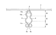
本実施形態の歯科矯正用口蓋側固定装置1は、図1に示すように、連結子2と、連結子2を口蓋に固定するための口蓋取付け部3とを備える。
連結子2は、口蓋に沿って配置されて端部側を歯に連結されるために使用される部材である。連結子2としては、ワイヤタイプ、バータイプ、メッシュ状タイプなど種々の形状が存在するが、本実施形態の連結子2は、ステンレスなどからなるワイヤである場合で例示する。もっとも本発明に係る連結子2の形状や素材は、口蓋内で使用可能であれば特に制限がない。
(構成)
本実施形態の歯科矯正用口蓋側固定装置1は、図1に示すように、連結子2と、連結子2を口蓋に固定するための口蓋取付け部3とを備える。
連結子2は、口蓋に沿って配置されて端部側を歯に連結されるために使用される部材である。連結子2としては、ワイヤタイプ、バータイプ、メッシュ状タイプなど種々の形状が存在するが、本実施形態の連結子2は、ステンレスなどからなるワイヤである場合で例示する。もっとも本発明に係る連結子2の形状や素材は、口蓋内で使用可能であれば特に制限がない。
上記口蓋取付け部3は、図1に示すように、連結子2の延在方向途中位置から当該延在方向に交差する方向に突設している。本実施形態の口蓋取付け部3は、連結子2の中央部から、連結子2の延在方向と直交する方向に突設している。そして、本実施形態の口蓋取付け部3は、口蓋から突出する2本のインプラント10、11の軸部10a、11bに着脱可能に取り付け可能な構造となっている(図3、図4参照)。
その口蓋取付け部3について詳説する。
上記口蓋取付け部3は、上記口蓋取付け部3は、口蓋から突出する2本のインプラント10、11に取り付けるための一対の弾性片4を有する。その一対の弾性片4は、一端部側が互いに連結して連結部9を構成すると共に、互いに同方向に延在している。そして、上記一端部(連結部9側)が固定端となると共に、各先端部4aが自由端となる。
上記口蓋取付け部3は、上記口蓋取付け部3は、口蓋から突出する2本のインプラント10、11に取り付けるための一対の弾性片4を有する。その一対の弾性片4は、一端部側が互いに連結して連結部9を構成すると共に、互いに同方向に延在している。そして、上記一端部(連結部9側)が固定端となると共に、各先端部4aが自由端となる。
上記口蓋取付け部3の上記連結部9側に第1取付け部3Aが形成されている。第1取付け部3Aは、上記インプラント10の少なくとも軸部10aを遊挿可能な大きさの空間S1を形成すると共に、上記空間S1内に配置したインプラント10が上記一対の弾性片4の先端部4aから離れる方向へ変位する際に当該インプラント10に当接して上記変位を規制する当接部分を備える。
本実施形態では、上記一対の弾性片4の連結部9側が上記第1取付け部3Aとなる。上記一対の弾性片4の連結部9側部分の間の空間S1が上記インプラント10の頭部10bを遊挿可能な空間S1となり、上記一対の弾性片4の一端部を連結した連結部9が上記当接部分となる。
本実施形態では、上記一対の弾性片4の連結部9側が上記第1取付け部3Aとなる。上記一対の弾性片4の連結部9側部分の間の空間S1が上記インプラント10の頭部10bを遊挿可能な空間S1となり、上記一対の弾性片4の一端部を連結した連結部9が上記当接部分となる。
また、上記連結部9は、半円弧状若しくはU字状の凹部6となっていてその凹部6内に、インプラント10の軸部10aを配置可能となっている。上記凹部6は、インプラント10の軸部10aを嵌め込み可能な寸法及び形状となっていても良い。例えば、上記凹部6の内周面は、上記軸部10aと同径若しくは略同径の円弧状とする。
また、上記一対の弾性片4の先端部4a側は、当該先端部4aに近づくにつれて一対の弾性片4間の間隔が狭くなり、当該一対の弾性片4の弾性力で上記突出する2本のインプラント10、11のうちの他方のインプラント11の軸部11aを上記連結部9側に向かう付勢力を持って挟持可能な弾性支持部3Bを形成する。
また、上記一対の弾性片4の先端部4a側は、当該先端部4aに近づくにつれて一対の弾性片4間の間隔が狭くなり、当該一対の弾性片4の弾性力で上記突出する2本のインプラント10、11のうちの他方のインプラント11の軸部11aを上記連結部9側に向かう付勢力を持って挟持可能な弾性支持部3Bを形成する。
本実施形態では、上記一対の弾性片4の先端部4a側は、当該先端部4aに近づくにつれて一対の弾性片4間の間隔が狭くなるように直線状若しくは略直線状に延び、一対の弾性片4の先端部4aが接触している。上記一対の弾性片4の先端部4a側部分の間に形成される楔空間S2は、連結部側の底辺がインプラント11の軸径よりも小さい3角形形状若しくは略3角形形状となっていて、上記一対の弾性片4の先端部4a側の3角形の頂角が鋭角となっている。なお、上記一対の弾性片4の先端部4aは必ずしも接触している必要はない。上記弾性支持部3Bを形成する一対の弾性片4の先端部4a側は、当該一対の弾性片4間の距離がインプラント11の軸径よりも小さくなっている。
上記一対の弾性片4の先端部4a側で形成される弾性支持部3Bの長さ(一対の弾性片4の延在方向の長さ)は、インプラント11の軸径の2倍以上4倍以下が好ましい。軸径の2倍以上の長さがあれば、各インプラント10、11の埋入誤差(インプラント10、11間の距離やインプラント10、11の軸の傾き誤差)を吸収可能と考えられ、逆に軸径の4倍を越える長さだと不必要に弾性片4を突出させることになると考えられるからである。
すなわち、上記弾性支持部3Bを形成する2つの弾性片4の先端部4a側は、当該先端部4aに向けて直線若しくは略直線状に延びていている。上記2つの弾性片4の先端部4a側は、他方の弾性片4側に凸の曲線状として、インプラント11の挟持部分での傾斜が急になるようにしてもよい。
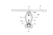
なお、上記3角形形状の空間S1を形成する一対の弾性片4の先端部4a側の弾性力F0で、図5のように、その間に配置したインプラント11に対し連結部9側への付勢力F1を発生するという観点からは、上記鋭角の頂角の角度は、5度以上40度以下が好ましい。これは、頂角の角度が小さいほど上記付勢力が小さくなり、逆に頂角の角度が大きくなるほど、インプラント11を挟持可能な長さ(一対の弾性片4の延在方向の長さ)が短くなるためである。上記挟持可能な長さが大きいほど、一対のインプラント10、11間の距離の誤差を吸収可能となる。
なお、上記3角形形状の空間S1を形成する一対の弾性片4の先端部4a側の弾性力F0で、図5のように、その間に配置したインプラント11に対し連結部9側への付勢力F1を発生するという観点からは、上記鋭角の頂角の角度は、5度以上40度以下が好ましい。これは、頂角の角度が小さいほど上記付勢力が小さくなり、逆に頂角の角度が大きくなるほど、インプラント11を挟持可能な長さ(一対の弾性片4の延在方向の長さ)が短くなるためである。上記挟持可能な長さが大きいほど、一対のインプラント10、11間の距離の誤差を吸収可能となる。
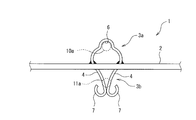
上記実施形態では、上記第1取付け部3A及び弾性支持部3Bを形成する部分の間に位置する上記一対の弾性片4の中間部3C分は、上記第1取付け部3A及び弾性支持部3Bよりも、一対の弾性片4間の距離が大きくなるように形成している。このため、全体として一対の弾性片4間に形成される空間S1は、略菱形形状となっている。なお、上記中間部3C分の形状や弾性片4間の間隔は特に制限はなく、図2に示すように、一対の弾性片4間に形成される空間S1が瓢箪(ダルマ形状)のような形状などでも良い。場合によっては、中間部3C分で一対の弾性片4が結合していても良い。但し、上記第1取付け部3Aで形成する空間S1がインプラント10の頭部10bを通過可能な大きさであることが好ましい。
更に、各弾性片4の先端部4aは、外側に丸まるように曲げられることで、フック7がそれぞれ形成されている。先端部4aにはRを付けておくことが好ましい。
上記弾性片4は、バネ力を有する材料から構成される。例えばステンレスやコバルトクロム鋼などのバネ鋼から構成すればよい。
本実施形態では、棒状弾性部材である1本のワイヤを使用し、そのワイヤの軸方向途中位置を折り曲げて、上記一対の弾性片4とし、その折り曲げによるU字部分が上記連結部9側に形成した第1取付け部3Aとした。そして、上記折曲げ部を連結子2に対し溶接等によって固定した。上記ワイヤは断面円形が好ましい。
上記弾性片4は、バネ力を有する材料から構成される。例えばステンレスやコバルトクロム鋼などのバネ鋼から構成すればよい。
本実施形態では、棒状弾性部材である1本のワイヤを使用し、そのワイヤの軸方向途中位置を折り曲げて、上記一対の弾性片4とし、その折り曲げによるU字部分が上記連結部9側に形成した第1取付け部3Aとした。そして、上記折曲げ部を連結子2に対し溶接等によって固定した。上記ワイヤは断面円形が好ましい。
(使用例や作用など)
次に、上記歯科矯正用口蓋側固定装置1の使用例を説明する。
歯科矯正用口蓋側固定装置1の連結子2の端部を、プライヤ等を使用して、図3のように実施する矯正に応じた形状に加工しておく。
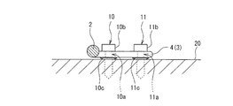
そして、口蓋20に対して前後に並ぶようにして2本のインプラント10、11を埋入する。インプラント10、11の頭部と口蓋20との間には、弾性片4を配置可能なだけの距離を設ける。ここで、インプラント10、11の軸径は、例えば1.6~1.8mmのものを使用する。2本のインプラント10、11間の距離は例えば、5mm以上8mm以下あれば、歯科矯正用口蓋側固定装置1を固定することができる。
次に、上記歯科矯正用口蓋側固定装置1の使用例を説明する。
歯科矯正用口蓋側固定装置1の連結子2の端部を、プライヤ等を使用して、図3のように実施する矯正に応じた形状に加工しておく。
そして、口蓋20に対して前後に並ぶようにして2本のインプラント10、11を埋入する。インプラント10、11の頭部と口蓋20との間には、弾性片4を配置可能なだけの距離を設ける。ここで、インプラント10、11の軸径は、例えば1.6~1.8mmのものを使用する。2本のインプラント10、11間の距離は例えば、5mm以上8mm以下あれば、歯科矯正用口蓋側固定装置1を固定することができる。
ここで、口蓋に埋め込む2本のインプラント10,11は、本発明の歯科矯正用口蓋側固定装置1の専用品である必要はない。通常口蓋に埋入する際に使用されているインプラントであれば、どのインプラントを使用しても構わない。すなわち、インプラント10,11としては汎用品を使用することが可能である。また、インプラント10,11の径が異なっていても良いし、種類も同じである必要はない。
本実施形態の例では、インプラント10,11として、図4に示すように、軸部10a、11aの上部に、径方向に張り出した傘状の張出部10c、11cが設けられていて、その頭部10b、11bと張出部10c、11cとの間の軸部位置に、一対の弾性片4を取付け可能となっている。頭部10b、11bと張出部10c、11cの間の隙間は、弾性片4を嵌め込み可能な大きさになっていれば良い。この場合には、口蓋20に対するインプラント10,11の埋入量に関わらず、取り付けた弾性片4に対する上下方向(インプラント軸方向)の位置決めが容易となる。更に、弾性片4は、口蓋20の粘膜と非接触の状態、つまり口蓋20の粘膜からわずかに浮いた状態でインプラント10,11に支持される。
次に、図3及び図4に示すように、一方のインプラント10の軸部10aを第1取付け部3Aの凹部6に位置するように配置すると共に、他方のインプラント10の軸部10aを弾性支持部3Bを構成する一対の弾性片4の先端部4a側に挟持させる。
このとき、一対の弾性片4の先端部4a側に挟持することで楔作用が発生して、一方のインプラント10が第1取付け部3Aの当接部分(凹部6)に接触していなくても、他方のインプラント11が連結部9側つまり一方のインプラント10側に付勢されることで、第1取付け部3Aの当接部分が一方のインプラント10に当接する。すなわち、図5のように、一対の弾性片4の先端部4a側間に略3角形形状の楔空間S2を形成すると、一対の弾性片4による挟持力F0によって、他方のインプラント11の軸部11aには他方のインプラント10に向かう付勢力F1が発生する。この付勢力F1によって、一方のインプラント10を相対的に当接部分に押し付ける力が発生する。同時に、上記のように他方のインプラント11の軸が挟持される。この結果、2本のインプラント10、11にしっかりと固定されることになる。実際に2本のインプラント10に固定してみたがしっかりと固定されることを確認している。
このとき、一対の弾性片4の先端部4a側に挟持することで楔作用が発生して、一方のインプラント10が第1取付け部3Aの当接部分(凹部6)に接触していなくても、他方のインプラント11が連結部9側つまり一方のインプラント10側に付勢されることで、第1取付け部3Aの当接部分が一方のインプラント10に当接する。すなわち、図5のように、一対の弾性片4の先端部4a側間に略3角形形状の楔空間S2を形成すると、一対の弾性片4による挟持力F0によって、他方のインプラント11の軸部11aには他方のインプラント10に向かう付勢力F1が発生する。この付勢力F1によって、一方のインプラント10を相対的に当接部分に押し付ける力が発生する。同時に、上記のように他方のインプラント11の軸が挟持される。この結果、2本のインプラント10、11にしっかりと固定されることになる。実際に2本のインプラント10に固定してみたがしっかりと固定されることを確認している。
上述のように、弾性支持部3Bの弾性力によって、他方のインプラント11が上記挟持によって固定されると共に当該他方のインプラント11が一方のインプラント10側に付勢される。この結果、歯科矯正用口蓋固定装置をしっかりと口蓋20に固定可能となる。このことは、2本のインプラント10、11間の距離が多少ずれたり、埋設したインプラント10、11の軸が多少傾いていても、口蓋取付け部3をインプラント10、11に取付け可能となる。これによって、口蓋20へのインプラント10、11の取り付け(埋入作業)が楽になる。なお、インプラント10、11の埋入作業は、従来のように、歯科矯正用口蓋側固定装置1を口蓋20においた状態で実施しても良い。
また、U字状などの凹部6に一方のインプラント10を入れることで、相対的に、一方のインプラント10の位置決めが容易となる。
さらに、一対のフック7間を、ゴムやワイヤ等の緊結具21で結ぶことで(図5参照)、弾性支持部3Bに挟持されているインプラント10が、更に外れ難くなる。
また、連結子2の矯正のための再調整を行う場合には、一対の弾性片4間を開くように力を掛けることで、口蓋20に埋め込んだインプラント10を外すことなく、歯科矯正用口蓋固定装置を取り外すことが可能となる。場合によっては、別の連結子2を有する上記口蓋取付け部3を備えた別の歯科矯正用口蓋側固定装置1を取り付けることもできる。
さらに、一対のフック7間を、ゴムやワイヤ等の緊結具21で結ぶことで(図5参照)、弾性支持部3Bに挟持されているインプラント10が、更に外れ難くなる。
また、連結子2の矯正のための再調整を行う場合には、一対の弾性片4間を開くように力を掛けることで、口蓋20に埋め込んだインプラント10を外すことなく、歯科矯正用口蓋固定装置を取り外すことが可能となる。場合によっては、別の連結子2を有する上記口蓋取付け部3を備えた別の歯科矯正用口蓋側固定装置1を取り付けることもできる。
また、上記一対の弾性片4を、ワイヤなどの1本の棒状若しくは帯状の弾性部材で形成することで、容易に上記口蓋取付け部3を形成可能となる。すなわち、上記一対の弾性片4は、互いに接近・離隔する方向にバネ力を発生可能となっていれば、その形状はこだわらない。
ここで、歯科矯正用口蓋側固定装置1の口蓋20の取付けは上記順番に限定しない。例えば、一方のインプラント10を埋入した状態で第1取付け部3Aを当該インプラント10の軸部10aに取り付け、その後に他方のインプラント10の埋入作業を実施したりしてもよい。
ここで、歯科矯正用口蓋側固定装置1の口蓋20の取付けは上記順番に限定しない。例えば、一方のインプラント10を埋入した状態で第1取付け部3Aを当該インプラント10の軸部10aに取り付け、その後に他方のインプラント10の埋入作業を実施したりしてもよい。
また、上記実施形態では、第1取付け部3Aを一対の弾性片4で形成する場合を例示しているがこれに限定しない。例えば、図6のように、インプラント10の頭部10bを遊挿可能な大きさの穴を連結部9側に設けて第1取付け部3Aとしても良い。
また、上記実施形態では、一対の弾性片4が左右対称な形状をする場合を例示しているが、左右対称の形状となっていなくても良い。
また、上記実施形態では、一対の弾性片4が左右対称な形状をする場合を例示しているが、左右対称の形状となっていなくても良い。
また、連結子1の形状も上記形状に限定されない。例えば図7に示す構成でも良い。この図7に示す歯科矯正用口蓋側固定装置1では、連結子1を口蓋取付け部3との連結部分で折り曲げている。そして、その連結子1の各端部を、それぞれ個別のレジンパッド30を介して、他のワイヤ31の一端部と接続している。他のワイヤ31は、奥歯側から歯列の外側に周り込むように延び、その他のワイヤ31の他端部は、歯に対して外周側から対向する位置に配置されている。なお、図7では、歯科矯正用口蓋側固定装置1を固定する2本のインプラントを省略して図示している。
図7に示す構成では、上記レジンパッド30が口蓋20の粘膜に接触した状態となっている。そのレンジパッド30は、上記歯科矯正用口蓋側固定装置1を介してインプラント(不図示)に固定されることで、口蓋20に安定した状態で固定される。
図7に示す構成では、上記レジンパッド30が口蓋20の粘膜に接触した状態となっている。そのレンジパッド30は、上記歯科矯正用口蓋側固定装置1を介してインプラント(不図示)に固定されることで、口蓋20に安定した状態で固定される。
1 歯科矯正用口蓋側固定装置
2 連結子
3 口蓋取付け部
3A 第1取付け部
3B 弾性支持部
3C 中間部
4 弾性片
4a 先端部
6 凹部(当接部分)
7 フック
9 連結部
10 (一方の)インプラント
10a 軸部
10b 頭部
11 (他方の)インプラント
11a 軸部
11b 頭部
20 口蓋
21 緊結具
30 レジンパッド
31 その他のワイヤ
F0 挟持力
F1 付勢力
S1 空間
S2 楔空間
2 連結子
3 口蓋取付け部
3A 第1取付け部
3B 弾性支持部
3C 中間部
4 弾性片
4a 先端部
6 凹部(当接部分)
7 フック
9 連結部
10 (一方の)インプラント
10a 軸部
10b 頭部
11 (他方の)インプラント
11a 軸部
11b 頭部
20 口蓋
21 緊結具
30 レジンパッド
31 その他のワイヤ
F0 挟持力
F1 付勢力
S1 空間
S2 楔空間
Claims (6)
- 口蓋へ脱着可能に取り付ける口蓋取付け部を備えた歯科矯正用口蓋側固定装置であって、
上記口蓋取付け部は、口蓋から突出する2本のインプラントに取り付けるための一対の弾性片を有し、上記一対の弾性片は、一端部側が互いに連結して連結部を構成すると共に、互いに同方向に延在しており、
上記口蓋取付け部の上記連結部側に、上記突出する2本のインプラントのうちの一方のインプラントを遊挿可能な大きさの空間を形成すると共に、上記空間内に配置したインプラントが上記一対の弾性片の先端部から離れる方向へ変位する際に当該インプラントに当接して上記変位を規制する当接部分を備えた第1取付け部が形成され、
上記一対の弾性片の先端部側が、当該先端部に近づくにつれて一対の弾性片間の間隔が狭くなり、当該一対の弾性片の弾性力で上記突出する2本のインプラントのうちの他方のインプラントを上記連結部側に向かう付勢力を持って挟持可能な弾性支持部を形成することを特徴とする歯科矯正用口蓋側固定装置。 - 上記当接部分は、上記先端部側に開口した凹部からなることを特徴とする請求項1に記載した歯科矯正用口蓋側固定装置。
- 上記弾性支持部を形成する2つの弾性片の先端部側は、当該先端部に向けて直線若しくは略直線状に延びていることを特徴とする請求項1又は請求項2に記載した歯科矯正用口蓋側固定装置。
- 1本の棒状若しくは帯状の弾性部材の軸方向途中位置を折り曲げて、上記一対の弾性片とし、その折り曲げによるU字部分が上記連結部側に形成した第1取付け部となることを特徴とする請求項1~請求項3のいずれか1項に記載した歯科矯正用口蓋側固定装置。
- 上記一対の弾性片の先端部にそれぞれフックを設けることを特徴とする請求項1~請求項4のいずれか1項に記載した歯科矯正用口蓋側固定装置。
- 口蓋に沿って配置されて端部側が歯に連結される連結子を有し、その連結子に上記連結部が連結し、一対の弾性片は、上記連結子の延在方向と交差する方向に延びていることを特徴とする請求項1~請求項5のいずれか1項に記載した歯科矯正用口蓋側固定装置。
Priority Applications (1)
| Application Number | Priority Date | Filing Date | Title |
|---|---|---|---|
| JP2012500480A JP5660507B2 (ja) | 2010-02-17 | 2011-01-12 | 歯科矯正用口蓋側固定装置 |
Applications Claiming Priority (2)
| Application Number | Priority Date | Filing Date | Title |
|---|---|---|---|
| JP2010032685 | 2010-02-17 | ||
| JP2010-032685 | 2010-02-17 |
Publications (1)
| Publication Number | Publication Date |
|---|---|
| WO2011102070A1 true WO2011102070A1 (ja) | 2011-08-25 |
Family
ID=44482679
Family Applications (1)
| Application Number | Title | Priority Date | Filing Date |
|---|---|---|---|
| PCT/JP2011/000084 Ceased WO2011102070A1 (ja) | 2010-02-17 | 2011-01-12 | 歯科矯正用口蓋側固定装置 |
Country Status (2)
| Country | Link |
|---|---|
| JP (1) | JP5660507B2 (ja) |
| WO (1) | WO2011102070A1 (ja) |
Cited By (1)
| Publication number | Priority date | Publication date | Assignee | Title |
|---|---|---|---|---|
| JP2020146224A (ja) * | 2019-03-13 | 2020-09-17 | 学校法人日本大学 | 歯列矯正器具 |
Citations (4)
| Publication number | Priority date | Publication date | Assignee | Title |
|---|---|---|---|---|
| US5967772A (en) * | 1998-12-09 | 1999-10-19 | Gray; James B. | Orthodontic anchor system |
| JP2001187071A (ja) * | 1999-12-28 | 2001-07-10 | Sankin Ind Co | 歯列矯正用支持体 |
| WO2006117841A1 (ja) * | 2005-04-27 | 2006-11-09 | Nihon University | 歯科矯正用インプラント用アバットメント、及びインプラント |
| JP2006314419A (ja) * | 2005-05-11 | 2006-11-24 | Univ Nihon | 歯科矯正用インプラント |
-
2011
- 2011-01-12 WO PCT/JP2011/000084 patent/WO2011102070A1/ja not_active Ceased
- 2011-01-12 JP JP2012500480A patent/JP5660507B2/ja active Active
Patent Citations (4)
| Publication number | Priority date | Publication date | Assignee | Title |
|---|---|---|---|---|
| US5967772A (en) * | 1998-12-09 | 1999-10-19 | Gray; James B. | Orthodontic anchor system |
| JP2001187071A (ja) * | 1999-12-28 | 2001-07-10 | Sankin Ind Co | 歯列矯正用支持体 |
| WO2006117841A1 (ja) * | 2005-04-27 | 2006-11-09 | Nihon University | 歯科矯正用インプラント用アバットメント、及びインプラント |
| JP2006314419A (ja) * | 2005-05-11 | 2006-11-24 | Univ Nihon | 歯科矯正用インプラント |
Cited By (1)
| Publication number | Priority date | Publication date | Assignee | Title |
|---|---|---|---|---|
| JP2020146224A (ja) * | 2019-03-13 | 2020-09-17 | 学校法人日本大学 | 歯列矯正器具 |
Also Published As
| Publication number | Publication date |
|---|---|
| JP5660507B2 (ja) | 2015-01-28 |
| JPWO2011102070A1 (ja) | 2013-06-17 |
Similar Documents
| Publication | Publication Date | Title |
|---|---|---|
| JP5719365B2 (ja) | 口腔内歯列矯正装置 | |
| WO2012011728A2 (ko) | 치열교정용 고정장치 | |
| CN101636123A (zh) | 正牙植入物盖以及包括其的正牙治疗组件 | |
| JP6294865B2 (ja) | 歯牙移動装置の組立方法 | |
| US20130344455A1 (en) | Dental implements | |
| JP5045878B2 (ja) | 歯列矯正用ブラケット | |
| KR101109531B1 (ko) | 브래킷 장착 지그 | |
| KR101043102B1 (ko) | 착탈식 틀니 | |
| JP5660507B2 (ja) | 歯科矯正用口蓋側固定装置 | |
| JP2009153577A (ja) | 歯列矯正具及びこれに用いられる付勢力付与具 | |
| KR100608304B1 (ko) | 치아교정용 앵커 | |
| KR101385527B1 (ko) | 치열 교정용 브라켓 | |
| US9084649B2 (en) | Orthodontic separator | |
| US7837468B2 (en) | Long-arm type upright molar tooth spring | |
| KR101646905B1 (ko) | 구개고정용장치 | |
| WO2008096937A1 (en) | The support device of elastic body for orthodontics | |
| KR100562581B1 (ko) | 골격형 ⅱ급 부정교합 교정장치 | |
| JP6185130B1 (ja) | 歯列矯正用インプラント装置 | |
| KR102080210B1 (ko) | 치열교정용 브라켓 조립체 | |
| KR102297927B1 (ko) | 치열교정용 브라켓 조립체 | |
| JP5728610B1 (ja) | 歯科矯正用インプラント装置 | |
| JP2006297052A (ja) | 歯列矯正具 | |
| JP2019033948A (ja) | 顎位矯正用ワイヤ、顎位矯正具、及び顎位矯正具の製造方法 | |
| KR102171983B1 (ko) | 치열교정용 브라켓 조립체 | |
| WO2006070957A1 (en) | Orthodontic anchoring device and method for using the anchoring device |
Legal Events
| Date | Code | Title | Description |
|---|---|---|---|
| 121 | Ep: the epo has been informed by wipo that ep was designated in this application |
Ref document number: 11744365 Country of ref document: EP Kind code of ref document: A1 |
|
| WWE | Wipo information: entry into national phase |
Ref document number: 2012500480 Country of ref document: JP |
|
| NENP | Non-entry into the national phase |
Ref country code: DE |
|
| 122 | Ep: pct application non-entry in european phase |
Ref document number: 11744365 Country of ref document: EP Kind code of ref document: A1 |