WO2011099557A1 - インクジェットプリンタ - Google Patents
インクジェットプリンタ Download PDFInfo
- Publication number
- WO2011099557A1 WO2011099557A1 PCT/JP2011/052860 JP2011052860W WO2011099557A1 WO 2011099557 A1 WO2011099557 A1 WO 2011099557A1 JP 2011052860 W JP2011052860 W JP 2011052860W WO 2011099557 A1 WO2011099557 A1 WO 2011099557A1
- Authority
- WO
- WIPO (PCT)
- Prior art keywords
- ultraviolet
- feed direction
- ink
- ultraviolet rays
- scanning direction
- Prior art date
- Legal status (The legal status is an assumption and is not a legal conclusion. Google has not performed a legal analysis and makes no representation as to the accuracy of the status listed.)
- Ceased
Links
Images




Classifications
-
- B—PERFORMING OPERATIONS; TRANSPORTING
- B41—PRINTING; LINING MACHINES; TYPEWRITERS; STAMPS
- B41J—TYPEWRITERS; SELECTIVE PRINTING MECHANISMS, i.e. MECHANISMS PRINTING OTHERWISE THAN FROM A FORME; CORRECTION OF TYPOGRAPHICAL ERRORS
- B41J11/00—Devices or arrangements of selective printing mechanisms, e.g. ink-jet printers or thermal printers, for supporting or handling copy material in sheet or web form
- B41J11/0015—Devices or arrangements of selective printing mechanisms, e.g. ink-jet printers or thermal printers, for supporting or handling copy material in sheet or web form for treating before, during or after printing or for uniform coating or laminating the copy material before or after printing
- B41J11/002—Curing or drying the ink on the copy materials, e.g. by heating or irradiating
- B41J11/0021—Curing or drying the ink on the copy materials, e.g. by heating or irradiating using irradiation
- B41J11/00214—Curing or drying the ink on the copy materials, e.g. by heating or irradiating using irradiation using UV radiation
-
- B—PERFORMING OPERATIONS; TRANSPORTING
- B41—PRINTING; LINING MACHINES; TYPEWRITERS; STAMPS
- B41J—TYPEWRITERS; SELECTIVE PRINTING MECHANISMS, i.e. MECHANISMS PRINTING OTHERWISE THAN FROM A FORME; CORRECTION OF TYPOGRAPHICAL ERRORS
- B41J11/00—Devices or arrangements of selective printing mechanisms, e.g. ink-jet printers or thermal printers, for supporting or handling copy material in sheet or web form
- B41J11/0015—Devices or arrangements of selective printing mechanisms, e.g. ink-jet printers or thermal printers, for supporting or handling copy material in sheet or web form for treating before, during or after printing or for uniform coating or laminating the copy material before or after printing
- B41J11/002—Curing or drying the ink on the copy materials, e.g. by heating or irradiating
- B41J11/0021—Curing or drying the ink on the copy materials, e.g. by heating or irradiating using irradiation
- B41J11/00212—Controlling the irradiation means, e.g. image-based controlling of the irradiation zone or control of the duration or intensity of the irradiation
Definitions
- the present invention relates to an inkjet printer that discharges ultraviolet curable ink.
- an inkjet head that ejects basic color ink, an inkjet head that ejects clear ink, and a plurality of ultraviolet rays that irradiate ultraviolet rays are ejected onto a carriage that moves in the scanning direction.
- An irradiation device is juxtaposed along the scanning direction.
- the surface smoothing of the transparent ink is promoted by turning on only the ultraviolet irradiation device arranged at the rearmost in the carriage movement direction.
- an object of the present invention is to provide an ink jet printer capable of forming a sufficiently glossy image.
- An ink jet printer includes a carriage that can reciprocate in a scanning direction, an ink discharge unit that is mounted on the carriage and discharges ultraviolet curable ink onto a recording medium, and a scanning direction of the ink discharge unit that is mounted on the carriage. And an ultraviolet irradiating unit that irradiates the recording medium with ultraviolet rays disposed on at least one of the front side and the rear side, and an inkjet in which the recording medium moves relative to the ink ejection unit in a feed direction orthogonal to the scanning direction In the printer, the ultraviolet irradiation unit is configured to block irradiation of ultraviolet rays from a position corresponding to a front portion in the feed direction of the ink discharge unit in the scanning direction.
- the ultraviolet curable ink applied to the upper layer is sufficiently smoothed by blocking the irradiation of the ultraviolet rays from the position corresponding to the front portion in the feed direction of the ink discharge means ( A sufficiently glossy image can be formed.
- the above-mentioned ultraviolet irradiation means irradiates the ultraviolet rays from a position corresponding to the front of the feed direction rather than the ink discharge means in the scanning direction.
- the ultraviolet curable ink applied to the upper layer can be cured after being sufficiently smoothed by irradiating ultraviolet rays from a position corresponding to the front in the feed direction from the ink discharge means. A glossy image can be formed.
- the ultraviolet irradiation means gradually increases the illuminance of the ultraviolet light irradiated from the position corresponding to the front of the ink ejection means in the scanning direction toward the feed direction.
- the UV curing applied to the upper layer by gradually increasing the illuminance of the ultraviolet rays emitted from the position corresponding to the front of the ink ejection means in the scanning direction toward the feed direction.
- the mold ink can be gradually cured. Thereby, rapid curing shrinkage of the ultraviolet curable ink can be suppressed, and generation of stripes between passes and reduction in glossiness can be suppressed.
- the ultraviolet irradiation means irradiates the ultraviolet light from a position corresponding to the rear part in the feed direction of the ink discharge means in the scanning direction.
- the ultraviolet curable ink discharged from the rear portion of the ink discharge means is cured, and then from the front portion of the ink discharge means.
- the discharged ultraviolet curable ink can be laminated. Thereby, it is possible to prevent the ultraviolet curable ink ejected from the rear part of the ink ejecting means from bleeding with the ultraviolet curable ink ejected from the front part of the ink ejecting means.
- An ink jet printer includes a carriage that can reciprocate in a scanning direction, an ink discharge unit that is mounted on the carriage and discharges ultraviolet curable ink onto a recording medium, and a scanning direction of the ink discharge unit that is mounted on the carriage.
- an ultraviolet irradiating unit that irradiates the recording medium with ultraviolet rays disposed on at least one of the front side and the rear side, and an inkjet in which the recording medium moves relative to the ink ejection unit in a feed direction orthogonal to the scanning direction
- the ink discharge unit is divided into a first discharge region disposed at the rear in the feed direction and a second discharge region disposed at the front in the feed direction, and the ultraviolet irradiation unit is arranged in the scanning direction.
- ultraviolet irradiation unit is arranged in the scanning direction.
- ultraviolet rays from the front in the feed direction Characterized by interrupting the irradiation.
- the ultraviolet curable ink applied to the upper layer is sufficiently smoothed (wet) by blocking the irradiation of ultraviolet rays from the front portion in the feed direction of the second irradiation region. Therefore, a sufficiently glossy image can be formed.
- the ink discharge means described above preferably discharges a colored ultraviolet curable ink from the first discharge region and discharges a light transmissive ultraviolet curable ink from the second discharge region.
- the colored ultraviolet curable ink is ejected from the first ejection area
- the translucent ultraviolet curable ink is ejected from the second ejection area.
- the UV curable ink having translucency can be smoothed on the upper layer of the colored UV curable ink. Thereby, the glossiness can be given to the image formed with the colored ultraviolet curable ink.
- the ultraviolet irradiation means described above irradiates ultraviolet rays from the rear part in the feed direction of the second irradiation region.
- the ultraviolet curable ink having translucency applied directly on the colored ultraviolet curable ink with ultraviolet rays.
- the bonding strength between the colored ultraviolet curable ink and the translucent ultraviolet curable ink can be improved.
- the above-described ultraviolet irradiation means irradiates ultraviolet rays from the first irradiation area corresponding to the first ejection area in the scanning direction.
- the ultraviolet curable ink discharged from the first discharge region is cured by irradiating the ultraviolet ray from the first irradiation region, and then the ultraviolet curable ink discharged from the second discharge region is stacked. Can do. Thereby, it is possible to prevent the ultraviolet curable ink ejected from the first ejection region from bleeding with the ultraviolet curable ink ejected from the second ejection region.
- the ultraviolet irradiation means described above irradiates ultraviolet rays from a third irradiation region corresponding to the front of the feed direction in the scanning direction rather than the second ejection region. In this way, by irradiating ultraviolet rays from the third irradiation area, the UV curable ink applied to the upper layer can be cured after being sufficiently smoothed, thus forming an appropriately glossy image. can do.
- the ultraviolet irradiation means described above gradually increases the illuminance of the ultraviolet light irradiated from the third irradiation region in the feed direction.
- the ultraviolet curable ink applied to the upper layer can be gradually cured by gradually increasing the illuminance of the ultraviolet rays irradiated from the third irradiation region in the feed direction.
- rapid curing shrinkage of the ultraviolet curable ink can be suppressed, and generation of stripes between passes and reduction in glossiness can be suppressed.
- the ultraviolet irradiation means described above makes the peak illuminance of ultraviolet rays irradiated from the third irradiation region smaller than the peak illuminance of ultraviolet rays irradiated from the first irradiation region.
- the curing rate of the ultraviolet curable ink in the upper layer can be slowed by making the peak illuminance of the ultraviolet rays irradiated from the third irradiation region smaller than the peak illuminance of the ultraviolet rays irradiated from the first irradiation region. .
- the ultraviolet irradiation means described above includes an ultraviolet irradiation unit that emits ultraviolet rays toward the recording medium, and a mask member that is provided on the recording medium side of the ultraviolet emission unit and blocks passage of ultraviolet rays emitted from the ultraviolet irradiation unit. It is good also as providing. As described above, since the illuminance of ultraviolet rays irradiated to the recording medium can be adjusted by the arrangement and shape of the mask member provided in the ultraviolet irradiation unit, the illuminance distribution of ultraviolet rays emitted from the ultraviolet irradiation means is easily adjusted. be able to.
- the rear end portion in the feed direction of the mask is gradually narrowed in the scanning direction toward the rear in the feed direction. In this way, by gradually reducing the width of the rear end portion in the feed direction of the mask toward the rear in the feed direction, the illuminance of the ultraviolet rays irradiating the recording medium is simply lowered gradually in the feed direction. be able to.
- the front end portion in the feed direction of the mask is gradually narrowed in the scanning direction toward the front in the feed direction. In this way, by gradually reducing the width of the front end portion in the feed direction of the mask toward the front in the feed direction, the illuminance of ultraviolet rays irradiating the recording medium can be gradually increased toward the feed direction. it can.
- the ultraviolet irradiation means may include a plurality of UVLEDs arranged in the feed direction and a lighting control unit that performs lighting control of the plurality of UVLEDs.
- the illuminance of ultraviolet rays in the feed direction irradiated on the recording medium can be adjusted, so that the illuminance distribution of ultraviolet rays emitted from the ultraviolet irradiation means can be easily achieved. Can be adjusted.
- a sufficiently glossy image can be formed.
- FIG. 1 is a schematic diagram illustrating an inkjet printer according to an embodiment. It is a bottom view of an ultraviolet irradiation device.
- FIG. 3 is a sectional view taken along line III-III in FIG. 2.
- FIG. 4 is a sectional view taken along line IV-IV in FIG. 2. It is the figure which showed the relationship between an ultraviolet irradiation device and an inkjet head. It is the figure which showed the illumination intensity distribution of the ultraviolet-ray irradiated to a medium. It is the figure which showed the illumination intensity distribution of the ultraviolet-ray irradiated to a medium. It is a top view which shows a mask. It is the figure which showed the photosensitive state of the photosensitive paper at the time of making an ultraviolet irradiation device light on photosensitive paper.
- the inkjet printer according to the embodiment is a multi-pass inkjet printer that forms an image in a plurality of passes, and discharges ultraviolet curable ink and cures the discharged ultraviolet curable ink by irradiating ultraviolet rays. Thus, an image is formed on the medium.
- the same or corresponding parts are denoted by the same reference numerals.
- FIG. 1 is a schematic diagram illustrating an ink jet printer according to an embodiment.
- the ink jet printer 1 includes a carriage 2 that can reciprocate in a scanning direction S, a head unit 3 mounted on the carriage 2, and a head unit 3 mounted on the carriage 2.
- An ultraviolet irradiation device 4a disposed in front of the scanning direction S and an ultraviolet irradiation device 4b mounted on the carriage 2 and disposed behind the head unit 3 in the scanning direction S are provided.
- the ink jet printer 1 transports the medium in the feed direction F perpendicular to the scanning direction S by the path width, and moves the carriage 2 in the scanning direction S to eject ultraviolet curable ink from the ink jet head 6.
- an image is formed on the medium by performing scanning by irradiating ultraviolet rays from the ultraviolet irradiation device 4a and the ultraviolet irradiation device 4b.
- the carriage 2 is held so as to be capable of reciprocating in the scanning direction S above a platen (not shown) through which the medium is conveyed.
- the carriage 2 is movably held by, for example, a guide rail (not shown) extending in the scanning direction S, and reciprocates in the scanning direction S along the guide rail by driving a drive mechanism (not shown) such as a drive motor. It can be moved.
- the head unit 3 is an ink discharge device in which a plurality of inkjet heads 6 (6a to 6d) for discharging ultraviolet curable ink are incorporated. Since the head unit 3 is mounted on the carriage 2, it is possible to discharge ultraviolet curable ink when moving in the scanning direction S accompanying the movement of the carriage 2.
- the inkjet heads 6a to 6d are provided along the scanning direction S, and are arranged in the order of the inkjet head 6a, the inkjet head 6b, the inkjet head 6c, and the inkjet head 6d from the front side in the scanning direction S. .
- Each inkjet head 6 is formed with a plurality of nozzles (not shown) that discharge ultraviolet curable ink as droplets.
- the plurality of nozzles form a nozzle row arranged so as to extend in the feed direction F, and two nozzle rows are formed in the scanning direction S in each inkjet head 6.
- Colored ultraviolet curable ink (hereinafter also referred to as “color ink”) is ejected from the inkjet head 6a and the inkjet head 6b disposed on the front side in the scanning direction S, and the inkjet head disposed on the rear side in the scanning direction S.
- 6c and the inkjet head 6d discharge ultraviolet curable ink having translucency (hereinafter also referred to as “clear ink”).
- magenta (M) color ink is ejected from the nozzle row on the front side in the scanning direction S formed on the inkjet head 6a, and from the nozzle row on the rear side in the scanning direction S formed on the inkjet head 6a.
- cyan (C) color ink is ejected.
- yellow (Y) color ink is ejected from the nozzle row on the front side in the scanning direction S formed on the inkjet head 6b, and black (from the nozzle row on the rear side in the scanning direction S formed on the inkjet head 6b.
- K color ink is ejected.
- clear ink (CL) is ejected from the two nozzle rows formed in each of the inkjet head 6c and the inkjet head 6d.
- the color ink is ejected only from the nozzle rows in the first ejection region A1 arranged in the rear half in the feed direction F, and the front half in the feed direction F. No color ink is ejected from the nozzle rows arranged in the nozzle array.
- the clear ink is ejected only from the nozzle row in the second ejection area A2 arranged in the front half in the feed direction F, and the rear half in the feed direction F. Clear ink is not ejected from the nozzle rows arranged in the nozzles.
- the color ink discharged from the first discharge area A1 of the inkjet head 6a and the inkjet head 6b is applied to the surface of the medium, and then the medium is fed in the feed direction F. Then, the clear ink ejected from the inkjet head 6c and the second ejection area A2 of the inkjet head 6d is applied to the upper layer (surface) of the color ink.
- each inkjet head 6 demonstrated as what changes the kind of ink discharged for every nozzle row, only one kind of ink is ejected from one inkjet head 6, and only the number of desired ink types is the inkjet head. 6 may be incorporated in the head unit 3.
- the ultraviolet irradiating device 4a and the ultraviolet irradiating device 4b are configured in the same manner, and irradiate the ultraviolet curable ink applied to the medium with ultraviolet rays to cure the ultraviolet curable ink. Therefore, hereinafter, the ultraviolet irradiation device 4a and the ultraviolet irradiation device 4b will be collectively described as the ultraviolet irradiation device 4.
- the ultraviolet irradiation device 4 since the ultraviolet irradiation device 4 is mounted on the carriage 2, it is possible to emit ultraviolet rays when reciprocating in the scanning direction S accompanying the movement of the carriage 2.
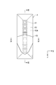
- FIG. 2 is a bottom view of the ultraviolet irradiation apparatus
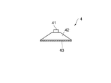
- FIG. 3 is a cross-sectional view taken along line III-III in FIG. 2
- FIG. 4 is a cross-sectional view taken along line IV-IV in FIG.
- the ultraviolet irradiation device 4 includes a UVLED unit 41, a reflecting plate 42, and a mask 43 as main components.
- the UVLED unit 41 is composed of a plurality of UVLEDs (ultraviolet light emitting diodes), and each UVLED is arranged in the feed direction F. In the present embodiment, eight UVLEDs are mounted on the UVLED unit 41.
- the UVLED unit 41 is irradiated with ultraviolet rays with high directivity, and the illuminance in the direction inclined by 60 ° with respect to the vertical direction is about 50% with respect to the illuminance in the vertical direction.
- the reflection plate 42 reflects the ultraviolet light emitted from the UVLED unit 41 to the media side.
- the reflecting plate 42 is formed in an umbrella shape that spreads from the UVLED unit 41 downward in the vertical direction with an inclination of about 60 ° so as to form a side surface of a truncated pyramid.
- a transparent cover 42 a is attached to the rectangular opening formed on the lower end surface of the reflecting plate 42, so that the opening of the reflecting plate 42 is blocked and ultraviolet rays can be transmitted.
- the ultraviolet rays emitted from the UVLED unit 41 have high directivity, the illuminance of ultraviolet rays below the reflecting plate 42 in the vertical direction is lower than the illuminance of ultraviolet rays below the UVLED 41 in the vertical direction.
- the mask 43 is formed in a thin sheet shape and is made of a material that blocks the passage of ultraviolet rays, and blocks the portion of the ultraviolet rays emitted from the ultraviolet irradiation device 4 to illuminate the medium with ultraviolet rays. Is to adjust.
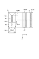
- FIG. 5 is a diagram showing the relationship between the ultraviolet irradiation device and the inkjet head.
- the ultraviolet irradiation device 4 includes the first irradiation region M1 of the ultraviolet irradiation device 4 corresponding to the first ejection region A1 of the inkjet head 6 in the scanning direction S and the first irradiation region M1 of the inkjet head 6 in the scanning direction S.
- the second irradiation area M2 of the ultraviolet irradiation device 4 corresponding to the second ejection area A2 and the third irradiation area M3 of the ultraviolet irradiation apparatus 4 corresponding to the front of the second ejection area A2 of the inkjet head 6 in the scanning direction S are divided.
- the first irradiation area M1 is a position (area) facing the first ejection area A1 when the carriage 2 moves in the scanning direction S, and the color ink ejected from the first ejection area A1 is the medium. It corresponds to a position (region) that passes above the application position applied to.
- the second irradiation area M2 is a position (area) facing the second ejection area A2 when the carriage 2 moves in the scanning direction S, and the clear ink ejected from the second ejection area A2 is applied to the medium. It corresponds to a position (region) that passes above the applied position.
- the third irradiation area M3 is a position (area) on the front side in the feed direction F of the second discharge area A2, and when the carriage 2 moves in the scanning direction S, the clear ink discharged from the second discharge area A2 is This corresponds to the position (area) on the front side in the feed direction F of the application position applied to the medium.
- the third irradiation region M3 is a region having a predetermined length in the feed direction F.
- the UVLED unit 41 has a rear end disposed about 10 mm ahead of the rear end of the inkjet head 6 in the feed direction F.
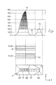
- FIGS. 6 and 7 are diagrams showing the illuminance distribution of ultraviolet rays irradiated on the medium.
- the illuminance distribution shown in FIGS. 6 and 7 is an illuminance distribution based on the illuminance of the vertical component of ultraviolet rays.
- the directivity of ultraviolet rays emitted from the UVLED unit 41 is high, and the distance between the ultraviolet irradiation device 4 and the medium is short, the inclination direction component of the ultraviolet rays is relative to the illuminance of the vertical component of the ultraviolet rays. It will be extremely small. For this reason, it can be considered that the illuminance distribution of the ultraviolet rays applied to the medium is substantially the same as the illuminance distribution shown in FIGS.
- the illuminance distribution of the ultraviolet rays irradiated on the medium includes the illuminance distribution corresponding to the first irradiation area M1, the illuminance distribution corresponding to the second irradiation area M2, and the third irradiation area M3. And the illuminance distribution corresponding to.
- the illuminance distribution of the first irradiation region M1 is generally high in illuminance.
- the ultraviolet irradiation device 4 moves in the scanning direction S, the ultraviolet curable ink in the entire first irradiation region M1 is cured.
- Illuminance is possible. That is, after the illuminance distribution in the feed direction F passing through the center of the scanning direction S gradually increases from the rear of the feed direction F to the front of the feed direction F, and reaches the first peak illuminance P1 with the highest illuminance, Illuminance decreases sharply near the rear edge.
- the illumination intensity of a vertical direction component will be about 780 mW / cm ⁇ 2 >, for example.
- the illuminance at the rear end of the feed direction F is, for example, the illuminance of the vertical component is about 400 mW / cm 2 and is lower than the first peak illuminance P1, but the ultraviolet curable ink can still be cured. Illuminance.
- the illuminance distribution of the second irradiation region M2 has an illuminance that is at least the path width on the rear side in the feed direction F, and the ultraviolet curable ink is cured when the ultraviolet irradiation device 4 moves in the scanning direction S. Illuminance that can be. Further, the illuminance distribution of the second irradiation area M2 is such that the illuminance on the front side in the feed direction F is low, and the ultraviolet curable ink cannot be cured when the ultraviolet irradiation device 4 moves in the scanning direction S. It has become.
- the illuminance distribution in the feed direction F passing through the center of the scanning direction S is such that the illuminance is such that the ultraviolet curable ink is cured at least for the pass width from the rear of the feed direction F to the front of the feed direction F.
- the bottom illuminance B continues to the rear end.
- the bottom illuminance B may be any illuminance as long as the ultraviolet curable ink is not cured.
- the illuminance of the vertical component is 0 mW / cm 2 or a value close to 0 mW / cm 2 .
- the illuminance distribution of the third irradiation region M3 is such that the illuminance on the rear side in the feed direction F is low, and the ultraviolet curable ink cannot be cured when the ultraviolet irradiation device 4 moves in the scanning direction S. ing.
- the illuminance distribution of the third irradiation region M3 is such that the illuminance on the front side in the feed direction F is high, and the illuminance that can cure the ultraviolet curable ink when the ultraviolet irradiation device 4 moves in the scanning direction S. It has become.
- the illuminance distribution in the feed direction F passing through the center of the scanning direction S is gradually increased after the bottom illuminance B continues for a while from the rear of the feed direction F to the front of the feed direction F, and the first peak illuminance P1.
- the illuminance gradually decreases.
- the second peak illuminance P2 is lower than the first peak illuminance P1, and for example, the illuminance of the vertical component is 180 mW / cm 2 and is about 1 ⁇ 4 of the first peak illuminance P1.
- the mask 43 is arranged at a position corresponding to the rear part in the feed direction F of the third irradiation region M3 from the front part of the second irradiation region M2 in the feed direction F, and the ultraviolet ray. It is attached to the media side of the irradiation device 4. Note that the mask 43 can be attached to the ultraviolet irradiation device 4 by fixing it to the reflecting plate 42, the cover 42a, or the like using an adhesive tape, an adhesive, or the like.
- FIG. 8 is a plan view showing the mask.
- the width of the mask 43 in the scanning direction S is simply expressed as “width”
- the length of the mask 43 in the feed direction F is simply expressed as “length”.
- the mask 43 is formed in a line-symmetric octagon with respect to a line L that passes through the center of the scanning direction S and extends in the feed direction F, and includes a rectangular first portion 43a and a first portion.
- a triangular second part 43b located on the rear side in the feed direction F of the part 43a and a pentagonal third part 43c located on the front side in the feed direction F of the first part 43a.
- the first portion 43a is formed in a rectangular shape having the same size as the width of the cover 42a in the scanning direction S, and blocks the ultraviolet rays irradiated from the second irradiation region M2.
- the width of the cover 42a in the scanning direction S is 36 mm
- the dimensions of the first portion 43a are, for example, a width of 36 mm and a length of 15 mm.
- the second portion 43b is formed in a triangular shape whose width gradually narrows toward the rear of the feed direction F (gradually widens toward the feed direction F), and blocks the ultraviolet rays irradiated from the second irradiation region M2. Is.
- the width of the cover 42a in the scanning direction S is 36 mm
- the dimensions of the second portion 43b are, for example, 36 mm in width (triangle base) and 5 mm in length (triangle height).
- the third portion 43c is formed in a pentagon whose width narrows in two steps toward the front in the feed direction F, and blocks the ultraviolet rays irradiated from the second irradiation region M2 and the third irradiation region M3. .
- the dimensions of the third portion 43c are, for example, 36 mm for the width (base of the pentagon), 25 mm for the length (pentagon height), The length of the inclination is 20 mm, and the length of the second-stage inclination is 5 mm.
- the mask 43 formed in this way is arranged in front of the center of the cover 42a in the feed direction F.
- the rear end of the mask 43 is located behind the center of the UVLED unit 41 and ahead of the rear end of the UVLED unit 41, for example, about 5 mm behind the center of the UVLED unit 41.
- the front end of the mask 43 is located in front of the front end of the UVLED unit 41.
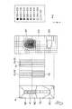
- FIG. 9 is a diagram showing the photosensitive state of the photosensitive paper when the ultraviolet irradiation device is turned on on the photosensitive paper.
- P1 shows the state of the photosensitive paper when the ultraviolet ray radiating device 4 is irradiated with ultraviolet rays while the carriage 2 is stationary
- P2 is a state where the carriage 2 is moved in the scanning direction S
- the state of the photosensitive paper when ultraviolet rays are irradiated from the ultraviolet irradiation device 4 is shown.
- the entire surface of the photosensitive paper is exposed.
- the color ink discharged from the first discharge region A1 is applied to the medium at the position corresponding to the first irradiation region M1.
- the film is cured by being irradiated with ultraviolet rays.
- the clear ink discharged from the second discharge region A2 is cured by being irradiated with ultraviolet rays immediately after being applied to the medium only in the lower layer, but in the upper layer. After being applied to the media, the surface is smoothed because the ultraviolet rays are not irradiated for a while.
- the clear ink discharged from the second discharge region A2 is irradiated with ultraviolet rays and cured.
- the color ink and the clear ink are ejected from the first ejection area A1 and the second ejection area A2 of the inkjet head 6 as the carriage 2 moves, and the ultraviolet irradiation device 4 Ultraviolet rays are emitted, and the media is sequentially conveyed in the feed direction F by the path width, whereby an image is formed on the media. For this reason, color ink is applied on the medium, and clear ink is applied on the upper layer of the color ink.
- the color ink discharged from the first discharge area A1 of the inkjet head 6 is irradiated with ultraviolet rays having an illuminance distribution in the first irradiation area M1
- this color ink has an illuminance immediately after being applied to the medium. It is cured by irradiation with high ultraviolet rays.
- the clear ink discharged from the second discharge area A2 of the inkjet head 6 is first irradiated with ultraviolet rays having an illuminance distribution in the second irradiation area M2.
- the lower clear ink is cured by being irradiated with ultraviolet rays immediately after being applied to the media, and the upper clear ink is irradiated with ultraviolet rays immediately after being applied to the media. Therefore, the surface spreads out along the media surface and the surface is smoothed.
- the upper layer clear ink whose surface is smoothed is irradiated with ultraviolet rays having an illuminance distribution in the third irradiation region M3, and the upper layer clear ink is cured.
- the clear ink applied to the upper layer is sufficiently smoothed by blocking the irradiation of ultraviolet rays from the front portion in the feed direction F of the second irradiation region M2. Therefore, a sufficiently glossy image can be formed.
- the color ink is ejected from the first ejection area A1 and the clear ink is ejected from the second ejection area A2, so that the clear ink can be applied to the upper layer of the color ink and the clear ink can be applied to the upper layer of the color ink. Can be smoothed. Thereby, glossiness can be given to the image formed with color ink.
- the illuminance distribution of the second irradiation region M2 is increased by at least the path width on the rear side in the feed direction F, and ultraviolet rays are irradiated at a position corresponding to the rear portion of the second discharge region A2 in the feed direction F.
- the clear ink applied directly above the color ink can be irradiated with ultraviolet rays. Thereby, the joint strength between the color ink and the clear ink can be improved.
- the color ink discharged from the first discharge area A1 is cured by setting the illuminance distribution of the first irradiation area M1 to an illuminance that can cure the ultraviolet curable ink in the entire first irradiation area M1. Later, the clear ink ejected from the second ejection area A2 can be stacked. Thereby, it is possible to prevent the color ink from bleeding with the clear ink.
- the illuminance distribution of the third irradiation region M3 can be increased so that the clear ink applied to the upper layer can be cured after being sufficiently smoothed. A feeling image can be formed.
- the clear ink applied to the upper layer can be gradually cured.
- contraction of clear ink can be suppressed, and the generation
- the curing speed of the clear ink in the upper layer can be slowed. Thereby, it is possible to further suppress the generation of stripes between passes and the reduction in glossiness.
- the illuminance of ultraviolet rays irradiated to the medium can be adjusted by the arrangement and shape of the mask 43 provided in the UVLED unit 41, and therefore the illuminance distribution of ultraviolet rays emitted from the ultraviolet irradiation device 4 Can be adjusted easily.
- the illuminance of ultraviolet rays applied to the medium can be simply set in the feed direction. It can be gradually lowered toward F.
- the illuminance of ultraviolet rays applied to the media can be gradually increased toward the feed direction F.
- the illuminance distribution in the first irradiation region M1 has been described as having high illuminance as a whole, but the illuminance distribution in the first irradiation region M1 may be any illuminance distribution.
- the illuminance distribution in the first irradiation region M1 may be an illuminance at which the ultraviolet curable ink is not cured as a whole.
- the ink jet head 6 is described as ejecting color ink and clear ink. However, only color ink or only clear ink may be ejected. In this case, it is preferable to discharge the color ink or the clear ink from all the nozzle rows regardless of the first discharge area A1 and the second discharge area A2 of the inkjet head 6. Even in such a case, it is only necessary to block the ultraviolet rays irradiated from the front in the feed direction F of the ultraviolet irradiation device 4, and the illuminance distribution in the first irradiation region M1 may be any illuminance distribution.
- the illuminance distribution in the first irradiation region M1 may be the illuminance that the ultraviolet curable ink is not cured as a whole, and the illuminance distribution in the first irradiation region M1 is the illuminance at which the rear portion in the feed direction F is cured by the ultraviolet curable ink Further, the illuminance at which the front part of the feed direction F is not cured by the ultraviolet curable ink may be used.
- the UV LED is used as the ultraviolet irradiation device.
- any type of metal halide lamp may be used as long as the ultraviolet curable ink can be irradiated with ultraviolet rays.
- the illuminance distribution of ultraviolet rays has been described as being adjusted by the mask 43, but may be adjusted by various other methods such as lighting control of each UVLED constituting the UVLED unit 41.
- each UVLED is individually controlled to be turned off, the UVLEDs arranged in the second irradiation region M2 are turned off, and the UVLEDs arranged in the first irradiation region M1 and the third irradiation region M3 are turned off.
- the above illuminance distribution can be realized by adjusting the illuminance of the arranged UVLED.
- the medium and the head unit 3 are moved relative to each other in the feed direction F by conveying the medium.
- the medium and the head are actually moved.
- Either unit 3 (carriage 2) or both of them may be moved.
- the present invention may be applied to a flat bed type inkjet printer including a flat bed on which a medium is placed and fixed, and a mechanism for moving the head unit 3 (carriage 2).
- the feed direction F of the present invention is opposite to the direction in which the head unit 3 (carriage 2) moves for printing.
Landscapes
- Health & Medical Sciences (AREA)
- General Health & Medical Sciences (AREA)
- Toxicology (AREA)
- Ink Jet (AREA)
- Coating Apparatus (AREA)
Abstract
Description
Claims (15)
- 走査方向において往復移動可能なキャリッジと、
前記キャリッジに搭載されて記録媒体に紫外線硬化型インクを吐出するインク吐出手段
と、
前記キャリッジに搭載されるとともに前記インク吐出手段の前記走査方向において前方及び後方の少なくとも一方に配置されて前記記録媒体に紫外線を照射する紫外線照射手段
と、を備え、
前記走査方向に直交するフィード方向に、前記記録媒体が前記インク吐出手段に対して相対的に移動するインクジェットプリンタであって、
前記紫外線照射手段は、
前記走査方向において前記インク吐出手段の前記フィード方向における前部に対応する位置からの紫外線の照射を遮断することを特徴とするインクジェットプリンタ。 - 前記紫外線照射手段は、
前記走査方向において前記インク吐出手段よりも前記フィード方向前方に対応する位置から紫外線を照射することを特徴とする請求項1に記載のインクジェットプリンタ。 - 前記紫外線照射手段は、
前記走査方向において前記インク吐出手段よりも前記フィード方向前方に対応する位置から照射する紫外線の照度を、前記フィード方向に向けて徐々に高くすることを特徴とする請求項2に記載のインクジェットプリンタ。 - 前記紫外線照射手段は、
前記走査方向において前記インク吐出手段の前記フィード方向における後部に対応する位置から紫外線を照射することを特徴とする請求項1~3の何れか1項に記載のインクジェットプリンタ。 - 走査方向において往復移動可能なキャリッジと、
前記キャリッジに搭載されて記録媒体に紫外線硬化型インクを吐出するインク吐出手段
と、
前記キャリッジに搭載されるとともに前記インク吐出手段の前記走査方向において前方及び後方の少なくとも一方に配置されて前記記録媒体に紫外線を照射する紫外線照射手段
と、を備え、
前記走査方向に直交するフィード方向に、前記記録媒体が前記インク吐出手段に対して相対的に移動するインクジェットプリンタであって、
前記インク吐出手段は、
前記フィード方向後方に配置される第一吐出領域と、前記フィード方向前方に配置される第二吐出領域と、に分割されており、
前記紫外線照射手段は、
前記走査方向において前記第二吐出領域に対応する第二照射領域のうち、前記フィード方向における前部からの紫外線の照射を遮断することを特徴とするインクジェットプリンタ。 - 前記インク吐出手段は、
前記第一吐出領域から有色の紫外線硬化型インクを吐出し、
前記第二吐出領域から透光性を有する紫外線硬化型インクを吐出することを特徴とする請求項5に記載のインクジェットプリンタ。 - 前記紫外線照射手段は、
前記第二照射領域の前記フィード方向における後部から紫外線を照射することを特徴とする請求項5に記載のインクジェットプリンタ。 - 前記紫外線照射手段は、
前記走査方向において前記第一吐出領域に対応する第一照射領域から紫外線を照射することを特徴とする請求項5に記載のインクジェットプリンタ。 - 前記紫外線照射手段は、
前記走査方向において前記第二吐出領域よりも前記フィード方向前方に対応する第三照射領域から紫外線を照射することを特徴とする請求項5に記載のインクジェットプリンタ。 - 前記紫外線照射手段は、
前記第三照射領域から照射する紫外線の照度を、前記フィード方向に向けて徐々に高くすることを特徴とする請求項9に記載のインクジェットプリンタ。 - 前記紫外線照射手段は、
前記第三照射領域から照射する紫外線のピーク照度を、前記第一照射領域から照射する紫外線のピーク照度よりも小さくすることを特徴とする請求項10に記載のインクジェットプリンタ。 - 前記紫外線照射手段は、
前記記録媒体に向けて紫外線を出射する紫外線照射部と、
前記紫外線出射部の前記記録媒体側に設けられて前記紫外線照射部から出射される紫外線の通過を遮断するマスク部材と、
を備えることを特徴とする請求項1又は5に記載のインクジェットプリンタ。 - 前記マスクの前記フィード方向における後端部は、前記走査方向における幅が前記フィード方向後方に向けて徐々に狭まっていることを特徴とする請求項12に記載のインクジェットプリンタ。
- 前記マスクの前記フィード方向における前端部は、前記走査方向における幅が前記フィード方向前方に向けて徐々に狭まっていることを特徴とする請求項12に記載のインクジェットプリンタ。
- 前記紫外線照射手段は、
前記フィード方向に配列される複数のUVLEDと、
前記複数のUVLEDの点灯制御を行う点灯制御部と、
を備えることを特徴とする請求項1又は5に記載のインクジェットプリンタ。
Priority Applications (2)
| Application Number | Priority Date | Filing Date | Title |
|---|---|---|---|
| JP2011553886A JP5247895B2 (ja) | 2010-02-10 | 2011-02-10 | インクジェットプリンタ |
| CN201180015168.4A CN102821960B (zh) | 2010-02-10 | 2011-02-10 | 喷墨打印机 |
Applications Claiming Priority (2)
| Application Number | Priority Date | Filing Date | Title |
|---|---|---|---|
| JP2010028062 | 2010-02-10 | ||
| JP2010-028062 | 2010-02-10 |
Publications (1)
| Publication Number | Publication Date |
|---|---|
| WO2011099557A1 true WO2011099557A1 (ja) | 2011-08-18 |
Family
ID=44367827
Family Applications (1)
| Application Number | Title | Priority Date | Filing Date |
|---|---|---|---|
| PCT/JP2011/052860 Ceased WO2011099557A1 (ja) | 2010-02-10 | 2011-02-10 | インクジェットプリンタ |
Country Status (3)
| Country | Link |
|---|---|
| JP (1) | JP5247895B2 (ja) |
| CN (1) | CN102821960B (ja) |
| WO (1) | WO2011099557A1 (ja) |
Cited By (8)
| Publication number | Priority date | Publication date | Assignee | Title |
|---|---|---|---|---|
| JP2016128254A (ja) * | 2015-01-05 | 2016-07-14 | 株式会社リコー | 画像形成装置および出力物の生産方法 |
| JP2017185825A (ja) * | 2017-07-14 | 2017-10-12 | 株式会社ミマキエンジニアリング | インクジェット印刷方法 |
| JP2019019372A (ja) * | 2017-07-14 | 2019-02-07 | 株式会社ミマキエンジニアリング | めっき方法 |
| JP2019217771A (ja) * | 2018-06-21 | 2019-12-26 | ハイデルベルガー ドルツクマシーネン アクチエンゲゼルシヤフトHeidelberger Druckmaschinen AG | インクジェット印刷によって物体に印刷を行う方法 |
| JP2020026059A (ja) * | 2018-08-10 | 2020-02-20 | ローランドディー.ジー.株式会社 | 印刷装置 |
| JP2021112868A (ja) * | 2020-01-20 | 2021-08-05 | 株式会社ミマキエンジニアリング | インクジェットプリンタおよびインクジェットプリンタの制御方法 |
| JP2021112823A (ja) * | 2020-01-16 | 2021-08-05 | ローランドディー.ジー.株式会社 | インクジェットプリンタおよび光の強度の確認方法 |
| EP3280592B1 (en) * | 2015-04-08 | 2023-04-19 | Electronics for Imaging, Inc. | Multilayer imaging with a high-gloss clear ink layer |
Families Citing this family (6)
| Publication number | Priority date | Publication date | Assignee | Title |
|---|---|---|---|---|
| JP2015048137A (ja) * | 2013-09-03 | 2015-03-16 | 株式会社ミマキエンジニアリング | 装飾体、装飾体組立体、装飾体製造方法、及び、インクジェットプリンタ |
| CN109927412A (zh) * | 2017-12-18 | 2019-06-25 | 星云电脑股份有限公司 | 输出高亮度透明油墨的多行程uv喷墨打印机及打印方法 |
| US11331935B2 (en) | 2018-03-30 | 2022-05-17 | Ricoh Company, Ltd. | Liquid discharge apparatus having individually controlled irradiators and control method |
| CN108638672B (zh) * | 2018-07-07 | 2024-05-07 | 东莞市图创智能制造有限公司 | 油墨固化装置及具有该油墨固化装置的打印机 |
| JP7066604B2 (ja) * | 2018-12-26 | 2022-05-13 | ローランドディー.ジー.株式会社 | 光硬化型インクジェットプリンタ |
| CN112373194B (zh) * | 2020-11-24 | 2025-02-18 | 北京美科艺数码科技发展有限公司 | 一种喷墨打印装置及其固化方法 |
Citations (4)
| Publication number | Priority date | Publication date | Assignee | Title |
|---|---|---|---|---|
| JP2002292907A (ja) * | 2001-03-30 | 2002-10-09 | Brother Ind Ltd | カラーインクジェット記録装置 |
| JP2004009483A (ja) * | 2002-06-06 | 2004-01-15 | Canon Inc | インクジェット記録装置 |
| JP2006289722A (ja) * | 2005-04-08 | 2006-10-26 | Konica Minolta Medical & Graphic Inc | インクジェット記録装置及びインクジェット記録方法 |
| JP2009226622A (ja) * | 2008-03-19 | 2009-10-08 | Mimaki Engineering Co Ltd | インクジェットプリンタ、印刷ユニットおよびその印刷方法 |
Family Cites Families (3)
| Publication number | Priority date | Publication date | Assignee | Title |
|---|---|---|---|---|
| EP1741555B2 (en) * | 2004-04-27 | 2015-07-29 | Konica Minolta Medical & Graphic, Inc. | Ink jet recorder |
| JP5139843B2 (ja) * | 2008-02-29 | 2013-02-06 | 株式会社ミマキエンジニアリング | インクジェットプリンタ及び印刷方法 |
| CN102099194B (zh) * | 2008-06-03 | 2014-08-06 | 罗兰Dg有限公司 | 喷墨式记录装置 |
-
2011
- 2011-02-10 JP JP2011553886A patent/JP5247895B2/ja active Active
- 2011-02-10 CN CN201180015168.4A patent/CN102821960B/zh active Active
- 2011-02-10 WO PCT/JP2011/052860 patent/WO2011099557A1/ja not_active Ceased
Patent Citations (4)
| Publication number | Priority date | Publication date | Assignee | Title |
|---|---|---|---|---|
| JP2002292907A (ja) * | 2001-03-30 | 2002-10-09 | Brother Ind Ltd | カラーインクジェット記録装置 |
| JP2004009483A (ja) * | 2002-06-06 | 2004-01-15 | Canon Inc | インクジェット記録装置 |
| JP2006289722A (ja) * | 2005-04-08 | 2006-10-26 | Konica Minolta Medical & Graphic Inc | インクジェット記録装置及びインクジェット記録方法 |
| JP2009226622A (ja) * | 2008-03-19 | 2009-10-08 | Mimaki Engineering Co Ltd | インクジェットプリンタ、印刷ユニットおよびその印刷方法 |
Cited By (13)
| Publication number | Priority date | Publication date | Assignee | Title |
|---|---|---|---|---|
| JP2016128254A (ja) * | 2015-01-05 | 2016-07-14 | 株式会社リコー | 画像形成装置および出力物の生産方法 |
| EP3280592B1 (en) * | 2015-04-08 | 2023-04-19 | Electronics for Imaging, Inc. | Multilayer imaging with a high-gloss clear ink layer |
| JP6993801B2 (ja) | 2017-07-14 | 2022-01-14 | 株式会社ミマキエンジニアリング | めっき方法 |
| JP2017185825A (ja) * | 2017-07-14 | 2017-10-12 | 株式会社ミマキエンジニアリング | インクジェット印刷方法 |
| JP2019019372A (ja) * | 2017-07-14 | 2019-02-07 | 株式会社ミマキエンジニアリング | めっき方法 |
| JP2019217771A (ja) * | 2018-06-21 | 2019-12-26 | ハイデルベルガー ドルツクマシーネン アクチエンゲゼルシヤフトHeidelberger Druckmaschinen AG | インクジェット印刷によって物体に印刷を行う方法 |
| JP2023039990A (ja) * | 2018-08-10 | 2023-03-22 | ローランドディー.ジー.株式会社 | 印刷装置 |
| JP2020026059A (ja) * | 2018-08-10 | 2020-02-20 | ローランドディー.ジー.株式会社 | 印刷装置 |
| JP7488325B2 (ja) | 2018-08-10 | 2024-05-21 | ローランドディー.ジー.株式会社 | 印刷装置 |
| JP2021112823A (ja) * | 2020-01-16 | 2021-08-05 | ローランドディー.ジー.株式会社 | インクジェットプリンタおよび光の強度の確認方法 |
| JP7539232B2 (ja) | 2020-01-16 | 2024-08-23 | ローランドディー.ジー.株式会社 | インクジェットプリンタおよび光の強度の確認方法 |
| US11318763B2 (en) * | 2020-01-20 | 2022-05-03 | Mimaki Engineering Co., Ltd. | Inkjet printer and control method for inkjet printer |
| JP2021112868A (ja) * | 2020-01-20 | 2021-08-05 | 株式会社ミマキエンジニアリング | インクジェットプリンタおよびインクジェットプリンタの制御方法 |
Also Published As
| Publication number | Publication date |
|---|---|
| CN102821960A (zh) | 2012-12-12 |
| JPWO2011099557A1 (ja) | 2013-06-13 |
| JP5247895B2 (ja) | 2013-07-24 |
| CN102821960B (zh) | 2014-12-03 |
Similar Documents
| Publication | Publication Date | Title |
|---|---|---|
| JP5247895B2 (ja) | インクジェットプリンタ | |
| JP5702191B2 (ja) | インクジェット記録装置、及び印刷方法 | |
| JP5453681B2 (ja) | 画像形成装置及び画像形成方法 | |
| US8393700B2 (en) | Inkjet recording device with independently controllable light emitting devices | |
| JP2009126071A (ja) | インクジェットプリンタ | |
| JP2009226692A (ja) | インクジェットプリンタ | |
| KR101549564B1 (ko) | 잉크젯 기록장치 | |
| WO2012053647A1 (ja) | インクジェット記録装置 | |
| JP2019209494A (ja) | 液体吐出装置及び液体吐出方法 | |
| CN102858543B (zh) | 图像形成装置以及图像形成方法 | |
| JP5378194B2 (ja) | インクジェット式画像形成装置 | |
| JP2019123217A (ja) | 印刷装置 | |
| KR20230130243A (ko) | 멀티헤드 잉크젯 프린팅의 얼룩 감소 led 제어 시스템 | |
| US10220644B2 (en) | Printing device and printing method | |
| JP2020026056A (ja) | 印刷装置 | |
| WO2021048953A1 (ja) | 印刷装置 | |
| JP2004001437A (ja) | インクジェットプリンタ、インク吐出ヘッドユニット及び画像形成方法 | |
| JP2004181941A (ja) | インクジェットプリンタ及び紫外線照射装置 | |
| JP5790098B2 (ja) | 液体吐出装置、及び、液体吐出方法 | |
| JP2020026059A (ja) | 印刷装置 | |
| WO2021141076A1 (ja) | 液体吐出装置及び液体吐出方法 | |
| JP2023174088A (ja) | 印刷装置 | |
| JP6310218B2 (ja) | インクジェットプリンタ | |
| JP2020026058A (ja) | 印刷装置 |
Legal Events
| Date | Code | Title | Description |
|---|---|---|---|
| WWE | Wipo information: entry into national phase |
Ref document number: 201180015168.4 Country of ref document: CN |
|
| 121 | Ep: the epo has been informed by wipo that ep was designated in this application |
Ref document number: 11742300 Country of ref document: EP Kind code of ref document: A1 |
|
| WWE | Wipo information: entry into national phase |
Ref document number: 2011553886 Country of ref document: JP |
|
| NENP | Non-entry into the national phase |
Ref country code: DE |
|
| 122 | Ep: pct application non-entry in european phase |
Ref document number: 11742300 Country of ref document: EP Kind code of ref document: A1 |