WO2011096404A1 - 建設機械の充電装置 - Google Patents
建設機械の充電装置 Download PDFInfo
- Publication number
- WO2011096404A1 WO2011096404A1 PCT/JP2011/052061 JP2011052061W WO2011096404A1 WO 2011096404 A1 WO2011096404 A1 WO 2011096404A1 JP 2011052061 W JP2011052061 W JP 2011052061W WO 2011096404 A1 WO2011096404 A1 WO 2011096404A1
- Authority
- WO
- WIPO (PCT)
- Prior art keywords
- voltage battery
- controller
- pressure
- low
- generator
- Prior art date
- Legal status (The legal status is an assumption and is not a legal conclusion. Google has not performed a legal analysis and makes no representation as to the accuracy of the status listed.)
- Ceased
Links
Images



Classifications
-
- H—ELECTRICITY
- H02—GENERATION; CONVERSION OR DISTRIBUTION OF ELECTRIC POWER
- H02J—ELECTRIC POWER NETWORKS; CIRCUIT ARRANGEMENTS OR SYSTEMS FOR SUPPLYING OR DISTRIBUTING ELECTRIC POWER; SYSTEMS FOR STORING ELECTRIC ENERGY
- H02J7/00—Circuit arrangements for charging or discharging batteries or for supplying loads from batteries
- H02J7/14—Circuit arrangements for charging or discharging batteries or for supplying loads from batteries for charging batteries from dynamo-electric generators driven at varying speed, e.g. on vehicle
- H02J7/1469—Regulation of the charging current or voltage otherwise than by variation of field
- H02J7/1492—Regulation of the charging current or voltage otherwise than by variation of field by means of controlling devices between the generator output and the battery
-
- E—FIXED CONSTRUCTIONS
- E02—HYDRAULIC ENGINEERING; FOUNDATIONS; SOIL SHIFTING
- E02F—DREDGING; SOIL-SHIFTING
- E02F9/00—Component parts of dredgers or soil-shifting machines, not restricted to one of the kinds covered by groups E02F3/00 - E02F7/00
- E02F9/20—Drives; Control devices
- E02F9/2058—Electric or electro-mechanical or mechanical control devices of vehicle sub-units
- E02F9/2091—Control of energy storage means for electrical energy, e.g. battery or capacitors
-
- H—ELECTRICITY
- H02—GENERATION; CONVERSION OR DISTRIBUTION OF ELECTRIC POWER
- H02J—ELECTRIC POWER NETWORKS; CIRCUIT ARRANGEMENTS OR SYSTEMS FOR SUPPLYING OR DISTRIBUTING ELECTRIC POWER; SYSTEMS FOR STORING ELECTRIC ENERGY
- H02J7/00—Circuit arrangements for charging or discharging batteries or for supplying loads from batteries
- H02J7/14—Circuit arrangements for charging or discharging batteries or for supplying loads from batteries for charging batteries from dynamo-electric generators driven at varying speed, e.g. on vehicle
- H02J7/1423—Circuit arrangements for charging or discharging batteries or for supplying loads from batteries for charging batteries from dynamo-electric generators driven at varying speed, e.g. on vehicle with multiple batteries
-
- Y—GENERAL TAGGING OF NEW TECHNOLOGICAL DEVELOPMENTS; GENERAL TAGGING OF CROSS-SECTIONAL TECHNOLOGIES SPANNING OVER SEVERAL SECTIONS OF THE IPC; TECHNICAL SUBJECTS COVERED BY FORMER USPC CROSS-REFERENCE ART COLLECTIONS [XRACs] AND DIGESTS
- Y02—TECHNOLOGIES OR APPLICATIONS FOR MITIGATION OR ADAPTATION AGAINST CLIMATE CHANGE
- Y02T—CLIMATE CHANGE MITIGATION TECHNOLOGIES RELATED TO TRANSPORTATION
- Y02T10/00—Road transport of goods or passengers
- Y02T10/80—Technologies aiming to reduce greenhouse gasses emissions common to all road transportation technologies
- Y02T10/92—Energy efficient charging or discharging systems for batteries, ultracapacitors, supercapacitors or double-layer capacitors specially adapted for vehicles
Definitions
- the present invention relates to a charging device for charging a battery of a construction machine, for example, a hybrid construction machine.
- JP2009-235717A discloses a charging device for a construction machine that stores electric power required by solenoids such as operation valves and a controller for controlling them in a low-voltage battery.
- the low voltage battery is connected to a generator that is rotated by the driving force of the engine, and the electric power generated by the generator is charged into the low voltage battery.
- the generator When the low-voltage battery is fully charged, the generator is idled with no load to stop the generator function. When the amount of electricity stored in the low-voltage battery decreases, the power generation function of the generator is automatically activated and the low-voltage battery is recharged.
- An object of the present invention is to provide a construction machine charging device that minimizes energy loss.
- an engine for rotating a pump a generator rotating by a driving force of the engine, a low-voltage battery for charging electric power from the generator, and the generator
- a charging device for a construction machine which is connected in parallel with the low-voltage battery and has a high-voltage battery for charging power from the generator.
- the charging device is provided between the switching circuit and the high-voltage battery, a switching circuit that performs switching for supplying power from the generator to either the low-voltage battery or the high-voltage battery, A high voltage conversion circuit for converting a low voltage to a high voltage, and whether or not a storage capacity of the low voltage battery exceeds a threshold value; A controller that outputs a signal for supplying power to the switching circuit to the switching circuit, and outputs a signal for charging the high-voltage battery to the switching circuit when the signal is larger than the threshold value.
- a charging device is provided.
- the power generated by the generator can be charged to the high voltage battery. Energy loss is kept to a minimum without causing the generator to run idle under no load.
- the controller monitors the storage status of the low-voltage battery, and if the storage capacity falls below the threshold, the generator's generated power is automatically guided to the low-voltage battery, so the low-voltage battery will not run out of power.
- FIG. 1 is a hydraulic circuit diagram of the first embodiment.
- FIG. 2 is a control circuit diagram of the first embodiment.
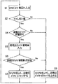
- FIG. 3 is a control flowchart of the first embodiment.
- FIG. 4 is a control circuit diagram of the second embodiment.
- the first embodiment shown in FIGS. 1 to 3 is a power shovel control system.
- the control system includes variable capacity first and second main pumps MP1 and MP2.
- a first circuit system is connected to the first main pump MP1, and a second circuit system is connected to the second main pump MP2.
- the first circuit system includes, in order from the upstream side, an operation valve 1 for controlling the turning motor RM, an operation valve 2 for the first speed arm for controlling the arm cylinder, and an operation valve 3 for the second speed boom for controlling the boom cylinder BC.
- a spare operation valve 4 for controlling the spare attachment and a left travel motor operation valve 5 for controlling the left travel motor are connected.
- Each of the operation valves 1 to 5 is connected to the first main pump MP1 via the neutral flow path 6 and the parallel path 7.
- a pilot pressure generating mechanism 8 is provided downstream of the operation valve 5 for the left travel motor in the neutral flow path 6.
- the pilot pressure generating mechanism 8 generates a high pilot pressure if the flow rate flowing therethrough is large, and generates a low pilot pressure if the flow rate is small.
- the neutral flow path 6 guides all or part of the fluid discharged from the first main pump MP1 to the tank T when all the operation valves 1 to 5 are in the neutral position or in the vicinity of the neutral position. In this case, since the flow rate passing through the pilot pressure generating mechanism 8 increases, a high pilot pressure is generated.
- a pilot flow path 9 is connected to the pilot pressure generating mechanism 8.
- the pilot flow path 9 is connected to a regulator 10 that controls the tilt angle of the first main pump MP1.
- the regulator 10 controls the discharge amount of the first main pump MP1 in inverse proportion to the pilot pressure. Accordingly, when the flow of the neutral flow path 6 becomes zero by full stroke of the operation valves 1 to 5, in other words, when the pilot pressure generated by the pilot pressure generating mechanism 8 becomes zero, the first main pump MP1 The discharge amount is kept at the maximum.
- the first pressure sensor 11 is connected to the pilot flow path 9. The pressure signal detected by the first pressure sensor 11 is input to the first controller C1.
- the second circuit system includes, in order from the upstream side, an operation valve 12 that controls the right traveling motor, a bucket operation valve 13 that controls the bucket cylinder, a boom first speed operation valve 14 that controls the boom cylinder BC, and An operation valve 15 for the second arm speed for controlling the arm cylinder is connected.
- the boom first speed operation valve 14 is provided with a sensor 14a for detecting an operation direction and an operation amount.
- the operation valves 12 to 15 are connected to the second main pump MP2 via the neutral flow path 16.
- the bucket operation valve 13 and the boom first speed operation valve 14 are connected to the second main pump MP2 via a parallel passage 17.
- a pilot pressure generating mechanism 18 is provided on the downstream side of the operation valve 15 for the second speed arm of the neutral flow path 16.
- the pilot pressure generating mechanism 18 functions in the same manner as the pilot pressure generating mechanism 8.
- a pilot flow path 19 is connected to the pilot pressure generating mechanism 18.
- the pilot flow path 19 is connected to a regulator 20 that controls the tilt angle of the second main pump MP2.
- the regulator 20 controls the discharge amount of the second main pump MP2 in inverse proportion to the pilot pressure. Therefore, when the flow of the neutral flow path 16 becomes zero by full stroke of the operation valves 12 to 15, in other words, when the pilot pressure generated by the pilot pressure generating mechanism 18 becomes zero, the second main pump MP2 The discharge amount is kept at the maximum.
- the second pressure sensor 21 is connected to the pilot flow path 19.
- the pressure signal detected by the second pressure sensor 21 is input to the first controller C1.
- the first and second main pumps MP1 and MP2 rotate coaxially with the driving force of one engine E.
- the engine E is provided with an alternator 22.
- the alternator 22 is rotated by the surplus output of the engine E and generates power.
- the electric power generated by the alternator 22 is charged to the low voltage battery 23 or the high voltage battery 24 via the charging device S.
- the charging device S will be described in detail later.
- the low voltage battery 23 is a 24V battery for construction machines
- the high voltage battery 24 is a battery used for the electric motor MG and the like.
- the passages 26 and 27 communicating with the turning motor RM are connected to the actuator port of the operation valve 1 connected to the first circuit system.
- Brake valves 28 and 29 are connected to both passages 26 and 27, respectively.
- one passage 26 is connected to the first main pump MP1, and the other passage 27 communicates with the tank T. Accordingly, the pressure fluid is supplied from the passage 26 to rotate the turning motor RM, and the return fluid from the turning motor RM is returned to the tank T through the passage 27.
- the brake valve 28 or 29 functions as a relief valve.
- the passages 26 and 27 are equal to or higher than the set pressure, the brake valves 28 and 29 are opened to guide the high-pressure side fluid to the low-pressure side. If the swing motor RM is rotating and the swing motor operating valve 1 is returned to the neutral position, the actuator port of the control valve 1 is closed. Thus, even if the actuator port of the operation valve 1 is closed, the turning motor RM continues to rotate with inertial energy. As the swing motor RM rotates with inertial energy, the swing motor RM pumps. In this case, a closed circuit is constituted by the passages 26 and 27, the swing motor RM, and the brake valve 28 or 29, and the inertia energy is converted into heat energy by the brake valve 28 or 29.
- a proportional solenoid valve 34 whose opening degree is controlled by the first controller C1 is provided in the passage 30 connecting the piston side chamber 31 of the boom cylinder BC and the operation valve 14 for the first speed of the boom.
- the proportional solenoid valve 34 maintains the fully open position in its normal state.
- variable displacement sub-pump SP that assists the outputs of the first and second main pumps MP1 and MP2 will be described.
- variable capacity sub-pump SP is rotated by the driving force of the electric motor MG that also serves as a generator.
- the variable capacity assist motor AM also rotates coaxially by the driving force of the electric motor MG.
- An inverter I is connected to the electric motor MG.
- the inverter I is connected to the first controller C1, and the first controller C1 can control the rotational speed of the electric motor MG and the like.
- tilt controllers 35 and 36 The tilt angles of the sub pump SP and the assist motor AM are controlled by tilt controllers 35 and 36.
- the tilt controllers 35 and 36 are controlled by the output signal of the first controller C1.
- the discharge passage 37 is connected to the sub pump SP.
- the discharge passage 37 branches into a first joining passage 38 that joins the discharge side of the first main pump MP1 and a second joining passage 39 that joins the discharge side of the second main pump MP2.
- First and second proportional electromagnetic throttle valves 40 and 41 whose opening degree is controlled by an output signal of the first controller C1 are provided in the first and second joining passages 38 and 39, respectively.
- connection passage 42 is connected to the assist motor AM.
- the connection passage 42 is connected to the passages 26 and 27 connected to the turning motor RM via the junction passage 43 and the check valves 44 and 45.
- the junction passage 43 is provided with an electromagnetic switching valve 46 that is controlled to be opened and closed by the first controller C1.
- a pressure sensor 47 is provided between the electromagnetic switching valve 46 and the check valves 44 and 45 to detect the pressure at the time of turning of the turning motor RM or the pressure at the time of braking. The pressure signal of the pressure sensor 47 is input to the first controller C1.
- a safety valve 48 is provided at a position of the merging passage 43 on the downstream side of the electromagnetic switching valve 46 with respect to the flow from the turning motor RM to the connection passage 42.
- the safety valve 48 maintains the pressure in the passages 26 and 27 and prevents the turning motor RM from running away when a failure occurs in the connection passages 42 and 43 such as the electromagnetic switching valve 46.
- a passage 49 communicating with the connection passage 42 is provided between the boom cylinder BC and the proportional solenoid valve 34.
- the passage 49 is provided with an electromagnetic on-off valve 50 controlled by the first controller C1.
- the charging device S is provided with a diode 51 that allows only a current flow from the alternator 22 to the low voltage battery 23 when the alternator 22 and the low voltage battery 23 are connected.
- a switch 52 is provided in parallel with the diode 51 for the alternator 22.
- the switch 52 is connected to the high voltage battery 24 via a high voltage conversion circuit 53 that converts a low voltage to a high voltage.
- the high voltage conversion circuit 53 may have the function of the switch 52.
- the second controller C2 is connected to each of the low voltage battery 23 and the switch 52.
- the second controller C2 is also connected to the first controller C1.
- the first controller C 1 is also connected to the high voltage battery 24 and has a function of checking the storage capacity of the high voltage battery 24.
- the second controller C2 has a function of checking whether or not the voltage of the low voltage battery 23 exceeds the threshold value, and controls the opening and closing of the switch 52.
- the first controller C1 checks the charging status of the high voltage battery 24. If the high voltage battery 24 is usable, the first controller C1 outputs a charge permission signal to the high voltage battery 24 to the second controller C2. To do.
- the second controller C2 switches when the low voltage battery 23 exceeds the threshold value, the charge permission signal is input from the first controller C1, and it is determined that the charged amount of the high voltage battery 24 is smaller than the reference value. 52 is closed, and the power of the alternator 22 is boosted through the high voltage conversion circuit 53 to charge the high voltage battery 24.
- the charging device S is modularized so that the system S can be incorporated into an existing device including the alternator 22, the low voltage battery 23, the high voltage battery 24, and the first controller C1.
- a second controller C2 is provided in addition to the first controller C1. Therefore, when the charging device is incorporated into the construction machine from the beginning, the controller can be integrated into one by providing the first controller C1 with the function of the second controller C2.
- the assist flow rate of the sub pump SP is set in advance, and how the first controller C1 controls the tilt angle of the sub pump SP, the tilt angle of the assist motor AM, the rotational speed of the electric motor MG, and the like. Then, determine the most efficient and implement each control.
- the entire amount of fluid discharged from the first main pump MP1 is guided to the tank T via the neutral flow path 6 and the pilot pressure generating mechanism 8. .
- the pilot pressure generated there becomes high and a relatively high pilot pressure is also introduced into the pilot flow path 9.
- the regulator 10 operates by the action of the high pilot pressure guided to the pilot flow path 9, and the discharge amount of the first main pump MP1 is kept to a minimum.
- the high pilot pressure signal at this time is input from the first pressure sensor 11 to the first controller C1.
- the pilot pressure generating mechanism 18 generates a relatively high pilot pressure as in the case of the first circuit system, and the high pressure is regulated by the regulator. 20 to keep the discharge amount of the second main pump MP2 to a minimum.
- the high pilot pressure signal at this time is input from the second pressure sensor 21 to the first controller C1.
- the first controller C1 When a relatively high pressure signal is input from the first and second pressure sensors 11 and 21 to the first controller C1, the first controller C1 causes the first and second main pumps MP1 and MP2 to maintain the minimum discharge amount.
- the tilt angle controllers 35 and 36 are controlled by determining that they are present, and the tilt angles of the sub pump SP and the assist motor AM are made zero or minimum.
- the first controller C1 When the first controller C1 receives a signal indicating that the discharge amounts of the first and second main pumps MP1 and MP2 are minimum, the first controller C1 may stop the rotation of the electric motor MG. The rotation may be continued.
- the electric motor MG When stopping the rotation of the electric motor MG, there is an effect that power consumption can be saved. If the electric motor MG continues to rotate, the sub-pump SP and the assist motor AM also continue to rotate, so there is an effect that the shock at the start of the sub-pump SP and the assist motor AM can be reduced. In any case, whether to stop the electric motor MG or continue to rotate may be determined in accordance with the application and usage status of the construction machine.
- the flow rate flowing through the neutral flow path 6 or 16 is reduced according to the operation amount, and accordingly, the pilot pressure generating mechanism The pilot pressure generated at 8 or 18 is reduced. If the pilot pressure decreases, the first main pump MP1 or the second main pump MP2 increases the tilt angle to increase the discharge amount.
- the first controller C1 When increasing the discharge amount of the first main pump MP1 or the second main pump MP2, the first controller C1 always keeps the electric motor MG rotated. That is, when the electric motor MG is stopped when the discharge amounts of the first and second main pumps MP1 and MP2 are the minimum, the first controller C1 detects that the pilot pressure has decreased and turns the electric motor MG off. Reboot.
- the first controller C1 controls the opening degree of the first and second proportional electromagnetic throttle valves 40 and 41 according to the pressure signals of the first and second pressure sensors 11 and 21, and apportions the discharge amount of the sub pump SP. Supplied to the first and second circuit systems.
- the first controller C1 opens the tilt angle of the sub pump SP and the first and second proportional electromagnetic throttle valves 40 and 41. Since the degree can be controlled, the number of pressure sensors can be reduced.
- one passage 26 communicates with the first main pump MP1, and the other The passage 27 communicates with the tank T and rotates the turning motor RM.
- the turning pressure at this time is kept at the set pressure of the brake valve 28. If the operation valve 1 is switched to the left in the drawing, the other passage 27 communicates with the first main pump MP1, and the one passage 26 communicates with the tank T, thereby rotating the turning motor RM. The turning pressure at this time is also maintained at the set pressure of the brake valve 29.
- control valve 1 for the swing motor If the control valve 1 for the swing motor is switched to the neutral position while the swing motor RM is turning, a closed circuit is formed between the passages 26 and 27, and the brake valve 28 or 29 maintains the brake pressure of the closed circuit. Then, inertial energy is converted into thermal energy.
- the pressure sensor 47 detects a turning pressure or a brake pressure and inputs a pressure signal to the first controller C1.
- the first controller C1 detects a pressure lower than the set pressure of the brake valves 28 and 29 within a range that does not affect the turning or braking operation of the turning motor RM
- the first controller C1 closes the electromagnetic switching valve 46. Switch from to open position.
- the electromagnetic switching valve 46 is switched to the open position, the pressure fluid guided to the turning motor RM flows into the merge passage 43 and is supplied to the assist motor AM via the safety valve 48 and the connection passage 42.
- the first controller C1 controls the tilt angle of the assist motor AM according to the pressure signal from the pressure sensor 47. It is as follows.
- the turning motor RM cannot be turned or the brake cannot be applied.
- the first controller C1 controls the load of the turning motor RM while controlling the tilt angle of the assist motor AM. That is, the first controller C1 controls the tilt angle of the assist motor AM so that the pressure detected by the pressure sensor 47 becomes substantially equal to the turning pressure or the brake pressure of the turning motor RM.
- the assist motor AM obtains a rotational force
- the rotational force acts on the electric motor MG that rotates coaxially.
- the rotational force of the assist motor AM acts as an assist force for the electric motor MG. Therefore, the power consumption of the electric motor MG can be reduced by the amount of the rotational force of the assist motor AM.
- the rotational force of the sub pump SP can be assisted by the rotational force of the assist motor AM.
- the assist motor AM and the sub pump SP are combined to exhibit a pressure conversion function.
- the fluid pressure flowing into the connection passage 42 is always lower than the pump discharge pressure.
- the assist motor AM and the sub pump SP exhibit a pressure increasing function.
- the output of the assist motor AM is determined by the product of the displacement volume Q1 per rotation and the pressure P1 at that time.
- the output of the sub pump SP is determined by the product of the displacement volume Q2 per revolution and the discharge pressure P2.
- the displacement volume Q2 is controlled by changing the tilt angle of the sub pump SP, a predetermined discharge pressure can be maintained in the sub pump SP by the output of the assist motor AM.
- the fluid pressure from the turning motor RM can be increased and discharged from the sub pump SP.
- the tilt angle of the assist motor AM is controlled so as to keep the pressure in the passages 26 and 27 at the turning pressure or the brake pressure. Therefore, when the fluid from the turning motor RM is used, the tilt angle of the assist motor AM is inevitably determined. In this way, the tilt angle of the sub pump SP is controlled in order to exert the pressure conversion function while the tilt angle of the assist motor AM is determined.
- the first controller C1 closes the electromagnetic switching valve 46 based on the pressure signal from the pressure sensor 47.
- the swing motor RM is not affected.
- the safety valve 48 functions so that the pressure in the passages 26 and 27 does not become unnecessarily low, thereby preventing the turning motor RM from running away.
- the first controller C1 determines whether the operator is going to raise or lower the boom cylinder BC.
- the first controller C1 keeps the proportional solenoid valve 34 in a normal state. In other words, the proportional solenoid valve 34 is kept in the fully open position.
- the first controller C1 controls the rotational speed of the electric motor MG and the tilt angle of the sub pump SP by keeping the electromagnetic on-off valve 50 in the illustrated closed position so that a predetermined discharge amount is secured from the sub pump SP. To do.
- the first controller C1 determines the lowering speed of the boom cylinder BC requested by the operator according to the operation amount of the operation valve 14. Is calculated, the proportional solenoid valve 34 is closed, and the solenoid on-off valve 50 is switched to the open position.
- the proportional solenoid valve 34 When the proportional solenoid valve 34 is closed and the solenoid on-off valve 50 is switched to the open position, the entire return fluid of the boom cylinder BC is supplied to the assist motor AM. If the flow rate consumed by the assist motor AM is less than the flow rate required to maintain the descending speed obtained by the operator, the boom cylinder BC cannot maintain the descending speed obtained by the operator. In this case, the first controller C1 has a flow rate higher than the flow rate consumed by the assist motor AM based on the operation amount of the operation valve 14, the tilt angle of the assist motor AM, the rotation speed of the electric motor MG, and the like. The opening degree of the proportional solenoid valve 34 is controlled so as to return to the tank T, and the lowering speed of the boom cylinder BC required by the operator is maintained.
- the assist motor AM When the fluid is supplied to the assist motor AM, the assist motor AM rotates.
- the rotational force of the assist motor AM acts on the electric motor MG that rotates coaxially, and acts as an assist force on the electric motor MG. Therefore, power consumption can be reduced by the amount of rotational force of the assist motor AM.
- the sub pump SP can be rotated only by the rotational force of the assist motor AM without supplying electric power to the electric motor MG.
- the assist motor AM and the sub pump SP perform a pressure conversion function in the same manner as described above.
- the first controller C1 closes the electromagnetic switching valve 46 based on the pressure signal from the pressure sensor 47.
- the tilt angle of the assist motor AM is based on the required lowering speed of the boom cylinder BC regardless of the turning pressure or the brake pressure. You can decide.
- the output of the sub pump SP is assisted by the output of the assist motor AM, and the flow rate discharged from the sub pump SP is apportioned by the first and second proportional electromagnetic throttle valves 40 and 41 to obtain the first and second circuits. Can be supplied to the grid.
- the electric motor MG when the electric motor MG is used as a generator with the assist motor AM as a drive source, the tilt angle of the sub-pump SP is set to zero and the load is almost unloaded. Therefore, if the output necessary for this is maintained, the electric motor MG can exhibit a power generation function using the output of the assist motor AM.
- the alternator 22 can generate power using the output of the engine E, or the electric motor MG can generate power using the assist motor AM.
- the generated power is stored in the high-voltage battery 24. Since the high-voltage battery 24 can be stored in the battery 24 using the home power supply 25, the power of the electric motor MG can be procured widely. .
- the solenoid of the operation valve, the electric system that controls the solenoid, or the low voltage battery 23 that supplies power to the first and second controllers C1, C2, etc. is charged with the power generated by the alternator 22.
- the charging device S functions as follows.
- the power of the alternator 22 is preferentially charged to the low voltage battery 23 via the diode 51 (step S1).
- the second controller C2 monitors whether or not the voltage V1 of the low voltage battery 23 is larger than a threshold value. If the voltage V1 is equal to or lower than the threshold value, the second controller C2 keeps the switch 52 in the off state (steps S2 and S3). That is, the charging device S gives priority to charging the low voltage battery 23.
- the second controller C2 determines whether or not a charge permission signal is input from the first controller C1 to the high voltage battery 24 (step S4). ).
- the first controller C1 constantly monitors the storage capacity of the high voltage battery 24 and outputs a storage amount voltage signal.
- the first controller C1 inputs the charged amount voltage signal of the high voltage battery 24 to the second controller C2 (step S5).
- the second controller determines whether or not the stored voltage of the high voltage battery 24 is greater than a reference value.
- the second controller C2 turns off the switch 52 (steps S6 and S3).
- the second controller C2 turns on the switch 52 (steps S6 and S7), and the electric power generated by the alternator 22 is converted by the high-voltage conversion circuit 53.
- the high voltage battery 24 is charged by boosting the voltage.
- the second controller C2 receives the charge permission signal from the first controller C1 to the high voltage battery 24 when the voltage V1 of the low voltage battery 23 exceeds the threshold value, and the high voltage battery 24 is charged.
- the switch 52 is turned on to charge the high voltage battery 24.
- a circuit for connecting the alternator 22 and the low voltage battery 23 and a circuit for connecting the alternator 22 and the high voltage battery 24 are one.
- the switch mechanism 54 is turned on and off.
- the alternator 22 is connected to a low voltage battery 23.
- the on / off of the high voltage battery of the switch mechanism 54 is controlled by the second controller C2.
- the control conditions are the same as in the first embodiment.
- This invention can be used for hybrid construction machines.
Landscapes
- Engineering & Computer Science (AREA)
- Power Engineering (AREA)
- Mining & Mineral Resources (AREA)
- Civil Engineering (AREA)
- General Engineering & Computer Science (AREA)
- Structural Engineering (AREA)
- Operation Control Of Excavators (AREA)
- Charge And Discharge Circuits For Batteries Or The Like (AREA)
- Secondary Cells (AREA)
- Control Of Eletrric Generators (AREA)
- Fluid-Pressure Circuits (AREA)
Abstract
Description
Claims (3)
- ポンプを回転するためのエンジンと、前記エンジンの駆動力によって回転する発電機と、前記発電機からの電力を充電するための低電圧バッテリーと、前記発電機に対して前記低電圧バッテリーと並列に接続され、前記発電機からの電力を充電するための高電圧バッテリーと、を有する建設機械の充電装置であって、
前記発電機からの電力を前記低電圧バッテリー及び前記高電圧バッテリーのいずれかに供給するための切換を行う切換回路と、
前記切換回路と前記高電圧バッテリーとの間に設けられ、低電圧を高電圧に変換する高電圧変換回路と、
前記低電圧バッテリーの蓄電容量がしきい値を超えているかどうかを判定し、前記しきい値以下の場合は、前記低電圧バッテリーに前記発電機の電力を供給するための信号を前記切換回路に出力し、前記しきい値よりも大きい場合は、前記高電圧バッテリーに充電させるための信号を前記切換回路に出力するコントローラと、
を備えた充電装置。 - 請求項1に記載の充電装置であって、
前記コントローラは、
前記低電圧バッテリーの蓄電容量を監視し、
前記低電圧バッテリーの蓄電容量が前記しきい値を超えているか否かを判定し、
前記高電圧バッテリーの蓄電容量が基準値を下回っているか否かを判定し、
前記低電圧バッテリーの蓄電容量が前記しきい値を超えていると判定し、かつ、前記高電圧バッテリーの蓄電容量が前記基準値を下回っていると判定した場合に、前記切換回路に信号を出力してそれを切換動作させ、前記発電機からの電力を、前記高電圧変換回路を介して前記高電圧バッテリーに充電させる、
充電装置。 - 請求項1に記載の充電装置であって、
前記切換回路は、
前記発電機と前記低電圧バッテリーとの間に設けられ、かつ、前記発電機から前記低電圧バッテリーへの電流の流れのみを許容するダイオードと、
前記ダイオードの上流側と前記高電圧変換回路との間に設けられたスイッチと、
を備える充電装置。
Priority Applications (4)
| Application Number | Priority Date | Filing Date | Title |
|---|---|---|---|
| US13/512,867 US9124133B2 (en) | 2010-02-08 | 2011-02-01 | Charging apparatus for construction machine |
| DE201111100478 DE112011100478T5 (de) | 2010-02-08 | 2011-02-01 | Ladeeinrichtung für Baumaschine |
| CN2011800056444A CN102696165A (zh) | 2010-02-08 | 2011-02-01 | 建筑机械的充电装置 |
| KR1020127006744A KR101504407B1 (ko) | 2010-02-08 | 2011-02-01 | 건설 기계의 충전 장치 |
Applications Claiming Priority (2)
| Application Number | Priority Date | Filing Date | Title |
|---|---|---|---|
| JP2010-025810 | 2010-02-08 | ||
| JP2010025810A JP2011166914A (ja) | 2010-02-08 | 2010-02-08 | 建設機械の充電装置 |
Publications (1)
| Publication Number | Publication Date |
|---|---|
| WO2011096404A1 true WO2011096404A1 (ja) | 2011-08-11 |
Family
ID=44355401
Family Applications (1)
| Application Number | Title | Priority Date | Filing Date |
|---|---|---|---|
| PCT/JP2011/052061 Ceased WO2011096404A1 (ja) | 2010-02-08 | 2011-02-01 | 建設機械の充電装置 |
Country Status (6)
| Country | Link |
|---|---|
| US (1) | US9124133B2 (ja) |
| JP (1) | JP2011166914A (ja) |
| KR (1) | KR101504407B1 (ja) |
| CN (1) | CN102696165A (ja) |
| DE (1) | DE112011100478T5 (ja) |
| WO (1) | WO2011096404A1 (ja) |
Families Citing this family (3)
| Publication number | Priority date | Publication date | Assignee | Title |
|---|---|---|---|---|
| JP5533716B2 (ja) * | 2011-02-08 | 2014-06-25 | トヨタ自動車株式会社 | 車両の発電制御システム |
| US10240322B2 (en) * | 2017-04-28 | 2019-03-26 | Caterpillar Global Mining Llc | Energy storage system |
| KR20180133018A (ko) * | 2017-06-02 | 2018-12-13 | 현대자동차주식회사 | 차량용 배터리 시스템 및 제어방법 |
Citations (4)
| Publication number | Priority date | Publication date | Assignee | Title |
|---|---|---|---|---|
| JPH09107639A (ja) * | 1995-08-07 | 1997-04-22 | Sawafuji Electric Co Ltd | バッテリアイソレータ |
| JPH1051907A (ja) * | 1996-07-26 | 1998-02-20 | Toyota Motor Corp | ハイブリッド車両 |
| JP2006304574A (ja) * | 2005-04-25 | 2006-11-02 | Toyota Motor Corp | 電源装置およびその制御方法 |
| JP2009235717A (ja) * | 2008-03-26 | 2009-10-15 | Kayaba Ind Co Ltd | ハイブリッド建設機械の制御装置 |
Family Cites Families (6)
| Publication number | Priority date | Publication date | Assignee | Title |
|---|---|---|---|---|
| JP2002330554A (ja) * | 2001-04-27 | 2002-11-15 | Kobelco Contstruction Machinery Ltd | ハイブリッド車両の電力制御装置および当該電力制御装置を備えたハイブリッド建設機械 |
| JP2003111301A (ja) * | 2001-09-28 | 2003-04-11 | Sanyo Electric Co Ltd | 太陽電池の電源装置 |
| JP2004229461A (ja) * | 2003-01-27 | 2004-08-12 | Toshiba Corp | 充電制御装置及び車両 |
| JP4741337B2 (ja) * | 2005-10-17 | 2011-08-03 | 新電元工業株式会社 | 充電装置 |
| JP4892057B2 (ja) * | 2007-03-28 | 2012-03-07 | 株式会社小松製作所 | ハイブリッド建設機械の制御方法およびハイブリッド建設機械 |
| JP2010025810A (ja) | 2008-07-22 | 2010-02-04 | Fujikura Ltd | ヘルスモニタリング用振動予測装置およびヘルスモニタリング用振動予測方法 |
-
2010
- 2010-02-08 JP JP2010025810A patent/JP2011166914A/ja active Pending
-
2011
- 2011-02-01 CN CN2011800056444A patent/CN102696165A/zh active Pending
- 2011-02-01 KR KR1020127006744A patent/KR101504407B1/ko not_active Expired - Fee Related
- 2011-02-01 US US13/512,867 patent/US9124133B2/en not_active Expired - Fee Related
- 2011-02-01 DE DE201111100478 patent/DE112011100478T5/de not_active Withdrawn
- 2011-02-01 WO PCT/JP2011/052061 patent/WO2011096404A1/ja not_active Ceased
Patent Citations (4)
| Publication number | Priority date | Publication date | Assignee | Title |
|---|---|---|---|---|
| JPH09107639A (ja) * | 1995-08-07 | 1997-04-22 | Sawafuji Electric Co Ltd | バッテリアイソレータ |
| JPH1051907A (ja) * | 1996-07-26 | 1998-02-20 | Toyota Motor Corp | ハイブリッド車両 |
| JP2006304574A (ja) * | 2005-04-25 | 2006-11-02 | Toyota Motor Corp | 電源装置およびその制御方法 |
| JP2009235717A (ja) * | 2008-03-26 | 2009-10-15 | Kayaba Ind Co Ltd | ハイブリッド建設機械の制御装置 |
Also Published As
| Publication number | Publication date |
|---|---|
| JP2011166914A (ja) | 2011-08-25 |
| US20120228948A1 (en) | 2012-09-13 |
| US9124133B2 (en) | 2015-09-01 |
| KR20120063481A (ko) | 2012-06-15 |
| DE112011100478T5 (de) | 2013-01-03 |
| KR101504407B1 (ko) | 2015-03-19 |
| CN102696165A (zh) | 2012-09-26 |
Similar Documents
| Publication | Publication Date | Title |
|---|---|---|
| JP5078692B2 (ja) | ハイブリッド建設機械の制御装置 | |
| JP5078693B2 (ja) | ハイブリッド建設機械の制御装置 | |
| JP5258341B2 (ja) | ハイブリッド建設機械の制御装置 | |
| JP5511425B2 (ja) | ハイブリッド建設機械の制御装置 | |
| US9026297B2 (en) | Control system for hybrid construction machine | |
| JP5377887B2 (ja) | ハイブリッド建設機械の制御装置 | |
| WO2011142187A1 (ja) | ハイブリッド建設機械 | |
| JP4942699B2 (ja) | ハイブリッド建設機械の制御装置 | |
| KR20110009118A (ko) | 하이브리드 건설기계의 제어장치 | |
| WO2011145432A1 (ja) | ハイブリッド作業機械 | |
| JP5197479B2 (ja) | ハイブリッド建設機械 | |
| KR101504407B1 (ko) | 건설 기계의 충전 장치 | |
| JP5398614B2 (ja) | ハイブリッド建設機械の制御装置 | |
| JP5078694B2 (ja) | ハイブリッド建設機械の制御装置 | |
| JP5265595B2 (ja) | ハイブリッド建設機械の制御装置 | |
| JP2009275872A (ja) | ハイブリッド建設機械の制御装置 | |
| JP2010261538A (ja) | ハイブリッド建設機械 | |
| JP2013145059A (ja) | 建設機械の制御方法及び制御装置 |
Legal Events
| Date | Code | Title | Description |
|---|---|---|---|
| 121 | Ep: the epo has been informed by wipo that ep was designated in this application |
Ref document number: 11739752 Country of ref document: EP Kind code of ref document: A1 |
|
| ENP | Entry into the national phase |
Ref document number: 20127006744 Country of ref document: KR Kind code of ref document: A |
|
| WWE | Wipo information: entry into national phase |
Ref document number: 13512867 Country of ref document: US |
|
| WWE | Wipo information: entry into national phase |
Ref document number: 1120111004788 Country of ref document: DE Ref document number: 112011100478 Country of ref document: DE |
|
| 122 | Ep: pct application non-entry in european phase |
Ref document number: 11739752 Country of ref document: EP Kind code of ref document: A1 |