WO2011096152A1 - 流体混合器および流体混合器を用いた装置 - Google Patents
流体混合器および流体混合器を用いた装置 Download PDFInfo
- Publication number
- WO2011096152A1 WO2011096152A1 PCT/JP2010/073659 JP2010073659W WO2011096152A1 WO 2011096152 A1 WO2011096152 A1 WO 2011096152A1 JP 2010073659 W JP2010073659 W JP 2010073659W WO 2011096152 A1 WO2011096152 A1 WO 2011096152A1
- Authority
- WO
- WIPO (PCT)
- Prior art keywords
- flow path
- fluid
- spiral
- channel
- main body
- Prior art date
- Legal status (The legal status is an assumption and is not a legal conclusion. Google has not performed a legal analysis and makes no representation as to the accuracy of the status listed.)
- Ceased
Links
Images


Classifications
-
- B—PERFORMING OPERATIONS; TRANSPORTING
- B01—PHYSICAL OR CHEMICAL PROCESSES OR APPARATUS IN GENERAL
- B01F—MIXING, e.g. DISSOLVING, EMULSIFYING OR DISPERSING
- B01F25/00—Flow mixers; Mixers for falling materials, e.g. solid particles
-
- B—PERFORMING OPERATIONS; TRANSPORTING
- B01—PHYSICAL OR CHEMICAL PROCESSES OR APPARATUS IN GENERAL
- B01F—MIXING, e.g. DISSOLVING, EMULSIFYING OR DISPERSING
- B01F23/00—Mixing according to the phases to be mixed, e.g. dispersing or emulsifying
- B01F23/40—Mixing liquids with liquids; Emulsifying
- B01F23/45—Mixing liquids with liquids; Emulsifying using flow mixing
-
- B—PERFORMING OPERATIONS; TRANSPORTING
- B01—PHYSICAL OR CHEMICAL PROCESSES OR APPARATUS IN GENERAL
- B01F—MIXING, e.g. DISSOLVING, EMULSIFYING OR DISPERSING
- B01F25/00—Flow mixers; Mixers for falling materials, e.g. solid particles
- B01F25/40—Static mixers
- B01F25/42—Static mixers in which the mixing is affected by moving the components jointly in changing directions, e.g. in tubes provided with baffles or obstructions
- B01F25/43—Mixing tubes, e.g. wherein the material is moved in a radial or partly reversed direction
- B01F25/433—Mixing tubes wherein the shape of the tube influences the mixing, e.g. mixing tubes with varying cross-section or provided with inwardly extending profiles
-
- B—PERFORMING OPERATIONS; TRANSPORTING
- B01—PHYSICAL OR CHEMICAL PROCESSES OR APPARATUS IN GENERAL
- B01F—MIXING, e.g. DISSOLVING, EMULSIFYING OR DISPERSING
- B01F23/00—Mixing according to the phases to be mixed, e.g. dispersing or emulsifying
- B01F23/20—Mixing gases with liquids
-
- B—PERFORMING OPERATIONS; TRANSPORTING
- B01—PHYSICAL OR CHEMICAL PROCESSES OR APPARATUS IN GENERAL
- B01F—MIXING, e.g. DISSOLVING, EMULSIFYING OR DISPERSING
- B01F25/00—Flow mixers; Mixers for falling materials, e.g. solid particles
- B01F25/40—Static mixers
-
- B—PERFORMING OPERATIONS; TRANSPORTING
- B01—PHYSICAL OR CHEMICAL PROCESSES OR APPARATUS IN GENERAL
- B01F—MIXING, e.g. DISSOLVING, EMULSIFYING OR DISPERSING
- B01F25/00—Flow mixers; Mixers for falling materials, e.g. solid particles
- B01F25/40—Static mixers
- B01F25/42—Static mixers in which the mixing is affected by moving the components jointly in changing directions, e.g. in tubes provided with baffles or obstructions
- B01F25/43—Mixing tubes, e.g. wherein the material is moved in a radial or partly reversed direction
- B01F25/433—Mixing tubes wherein the shape of the tube influences the mixing, e.g. mixing tubes with varying cross-section or provided with inwardly extending profiles
- B01F25/4331—Mixers with bended, curved, coiled, wounded mixing tubes or comprising elements for bending the flow
-
- B—PERFORMING OPERATIONS; TRANSPORTING
- B01—PHYSICAL OR CHEMICAL PROCESSES OR APPARATUS IN GENERAL
- B01F—MIXING, e.g. DISSOLVING, EMULSIFYING OR DISPERSING
- B01F25/00—Flow mixers; Mixers for falling materials, e.g. solid particles
- B01F25/40—Static mixers
- B01F25/42—Static mixers in which the mixing is affected by moving the components jointly in changing directions, e.g. in tubes provided with baffles or obstructions
- B01F25/43—Mixing tubes, e.g. wherein the material is moved in a radial or partly reversed direction
- B01F25/434—Mixing tubes comprising cylindrical or conical inserts provided with grooves or protrusions
- B01F25/4341—Mixing tubes comprising cylindrical or conical inserts provided with grooves or protrusions the insert being provided with helical grooves
-
- B—PERFORMING OPERATIONS; TRANSPORTING
- B01—PHYSICAL OR CHEMICAL PROCESSES OR APPARATUS IN GENERAL
- B01F—MIXING, e.g. DISSOLVING, EMULSIFYING OR DISPERSING
- B01F23/00—Mixing according to the phases to be mixed, e.g. dispersing or emulsifying
- B01F23/40—Mixing liquids with liquids; Emulsifying
- B01F23/48—Mixing liquids with liquids; Emulsifying characterised by the nature of the liquids
- B01F23/483—Mixing liquids with liquids; Emulsifying characterised by the nature of the liquids using water for diluting a liquid ingredient, obtaining a predetermined concentration or making an aqueous solution of a concentrate
Definitions
- the present invention relates to a fluid mixer used for fluid transport piping in various industries such as chemical factories, semiconductor manufacturing fields, food fields, medical fields, and bio fields, and in particular, concentration distribution and temperature distribution in the fluid flow direction.
- the present invention relates to a fluid mixer that can be uniformly mixed, mixed, and stirred, and an apparatus using the fluid mixer.
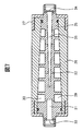
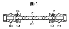
- the static mixer element 151 is formed by integrally connecting a plurality of minimum unit members in series so that twist directions are alternately different, with a rectangular plate twisted 180 degrees around its longitudinal axis as a minimum unit member. It has a combined structure.
- the static mixer element 151 is disposed in the tube 152, the mail connector 153 is attached to both ends of the tube 152, the flare 155 is attached, and the tightening nut 154 is tightened to form a static mixer.
- the outer diameter of the static mixer element 151 is designed to be substantially equal to the inner diameter of the tube 152 so that the fluid is effectively stirred.
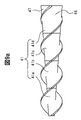
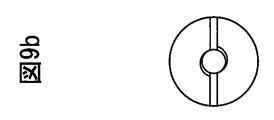
- the concentration distribution in the radial direction of the pipe is evenly uniform as shown in FIG. 19a.
- the concentration distribution in the axial direction (flow direction) cannot be made uniform. Therefore, for example, when water and a chemical solution are mixed and flowed upstream of the static mixer, if the mixing ratio of the chemical solution temporarily increases, the static mixer passes through the static mixer in a state where the concentration is partially increased in the flow path.
- a method of flowing a fluid (not shown) and the like can be mentioned.
- a large space is required to install the tank, and the apparatus becomes large.
- a pump, piping, etc. are needed for transporting a fluid again from a tank, the number of members to use increases and the cost for constructing a piping line generate
- fluid stays in the tank, which causes generation of bacteria. The bacteria generated in the tank flow into the piping line and adhere to the semiconductor wafer in the semiconductor production line, causing defective products.
- the object of the present invention has been made in view of the problems of the prior art as described above, and is a fluid mixing with a compact configuration that can uniformly mix and agitate the concentration distribution and temperature distribution in the fluid flow direction without unevenness.
- the fluid mixer according to the present invention includes a main flow path including a first flow path and a second flow path, and is formed substantially concentrically around the second flow path with respect to the second flow path, and is positioned mutually in the circumferential direction. And a plurality of spiral channels each having one end communicating with the first channel and a plurality of spiral channels branching from a plurality of locations in the flow direction of the second channel and a plurality of locations in the flow direction of the plurality of spiral channels.
- a plurality of branch flow channels respectively communicating with the spiral flow channel, a fluid inlet portion provided at one of the first flow channel and the second flow channel, and any one of the first flow channel and the second flow channel.
- a fluid outlet provided at the other opening end.
- FIG. 1 is a perspective view showing a schematic configuration of a fluid mixer according to a first embodiment of the present invention.
- FIG. 2 is a schematic diagram showing an apparatus for measuring the concentration of fluid using the fluid mixer of FIG.
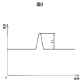
- FIG. 3 is a graph in which the concentration on the upstream side of the fluid mixer of FIG. 2 is measured.
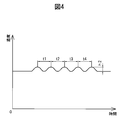
- FIG. 4 is a graph obtained by measuring the concentration on the downstream side of the fluid mixer of FIG.
- FIG. 5 is a partial longitudinal sectional view showing the inside of the fluid mixer according to the second embodiment of the present invention.
- FIG. 6 is a partial longitudinal sectional view showing a modification of FIG.
- FIG. 7 is a longitudinal sectional view showing another modification of FIG.
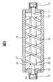
- FIG. 8 is a longitudinal sectional view showing a fluid mixer according to a third embodiment of the present invention.
- FIG. 9a is a left side view of the main body of FIG.
- FIG. 9b is a front view of the main body of FIG.
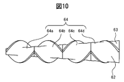
- FIG. 10 is a front view showing an example in which the spiral groove of the main body is changed.
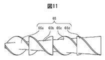
- FIG. 11 is a diagram showing a modification of FIG.
- FIG. 12a is a diagram illustrating a modification of FIG. 9a.
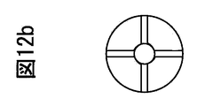
- 12b is a diagram showing a modification of FIG. 9b.
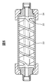
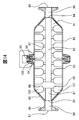
- FIG. 13 is a longitudinal sectional view showing a fluid mixer according to a fourth embodiment of the present invention.
- FIG. 14 is a longitudinal sectional view showing a fluid mixer according to a fifth embodiment of the present invention.
- FIG. 15 is a longitudinal sectional view showing a fluid mixer according to a sixth embodiment of the present invention.
- FIG. 16 is a schematic view showing an embodiment of an apparatus using the fluid mixer of the present invention.
- FIG. 17 is a schematic view showing another embodiment of the apparatus using the fluid mixer of the present invention.
- FIG. 18 is a longitudinal sectional view showing a conventional static mixer.
- FIG. 19 a is a schematic diagram showing a fluid stirring state by the static mixer of FIG. 18.
- FIG. 19b is a schematic diagram showing a fluid stirring state by the static mixer of FIG.
- FIG. 20 is a longitudinal sectional view showing a branch dilution apparatus as a comparative example of the present invention.
- FIG. 1 is a perspective view showing a schematic configuration of a fluid mixer according to a first embodiment.
- This fluid mixer has a mixing channel for mixing different kinds of fluids.
- the mixing channel is formed by a tube made of, for example, PFA (tetrafluoroethylene / perfluoroalkyl vinyl ether copolymer resin). Note that the mixing channel can be formed of other materials such as metal piping.
- the mixing channel includes a fluid inlet 1 into which a fluid flows, a first channel 2 in which the fluid inlet 1 is provided at one end, a fluid outlet 3 from which the fluid flows out, and a fluid outlet at the opposite end of the fluid inlet 1. And a first spiral channel 5 and a second spiral channel 6 disposed concentrically around the second channel 4 with the channels 2 and 4 as the central axis of the spiral. , A pair of communication channels 10a and 10b communicating the first channel 2 with the first spiral channel 5 and the second spiral channel 6, the second channel 4, the first spiral channel 5 and the second spiral flow. A plurality of branch flow paths 7a to 7e and 7f to 7j communicating with the path 6 are provided.
- the 1st flow path 2 and the 2nd flow path 4 are the linear flow paths arrange
- the first spiral channel 5 and the second spiral channel 6 have substantially the same shape, and the channel cross-sectional shapes with respect to the channel axis are the same.
- the centers of the spirals of the spiral channels 5 and 6 are on the same axis, and the spiral channels 5 and 6 are arranged at regular intervals in the axial direction. In other words, the positions (phases) are shifted from each other in the circumferential direction so as not to cross each other.
- the communication channels 10a and 10b and the branch channels 7a to 7j are formed in a substantially linear shape, that is, in a straight line shape or a substantially straight line shape.
- Each communication channel 10 a, 10 b is branched from the end of the first channel 2 on the opposite side of the fluid inlet 1.
- Each of the communication channels 10a and 10b extends in a position that is axially symmetric in a substantially vertical plane with respect to the first channel 2, that is, in a vertical or substantially vertical plane.
- the communication channels 10a and 10b are connected to the fluid inlet side end portions of the first spiral channel 5 and the second spiral channel 6, respectively, and the first channel 2 and the first spiral flow via the communication channels 10a and 10b.
- the channel 5 and the second spiral channel 6 communicate with each other.
- Each of the branch channels 7 a to 7 j is branched from a plurality of locations in the flow direction of the second channel 4.
- a pair of branch channels 7a and 7f are branched from the fluid inlet side end of the second channel 4, and thereafter, a pair of branch channels 7b and 7g, a pair of branch channels 7c and 7h, a pair of The branch channels 7d and 7i and the pair of branch channels 7e and 7j are respectively branched from the second channel 4 along the fluid flow direction.
- the branch flow paths 7a to 7e and the branch flow paths 7f to 7j are respectively extended in axially symmetric positions in a substantially vertical plane with respect to the second flow path 4, that is, in a vertical or substantially vertical plane.
- the branch flow paths 7a to 7e are each connected to the first spiral flow path 5, and the spiral flow paths 7f to 7j are respectively connected to the second spiral flow paths 6, and the second flow is made via the branch flow paths 7a to 7j.
- the channel 4, the first spiral channel 5, and the second spiral channel 6 communicate with each other.
- branch channels 7e and 7j are connected to the ends of the first spiral channel 5 and the second spiral channel 6, respectively.
- the pair of communication channels 10a and 10b at the end of the first channel 2 and the pair of branch channels 7a to 7e and 7f to 7j at a plurality of locations of the second channel 4 are provided at axially symmetrical positions.
- the positions where the communication channels 10a and 10b and the branch channels 7a to 7e and 7f to 7j are provided are not limited thereto.
- the spiral flow path (spiral groove) of the present application is not only a spiral structure that always spirally rotates in the positive direction along the flow axis direction, but also spiral rotation in the positive direction along the flow path axis direction. Also included are those in which the direction of the helix changes alternately forward and backward so that the rotation is in the reverse direction and then the forward direction and the reverse direction (see FIG. 10).
- a plurality of spiral channels branched from the first channel 2 may be configured so that the plurality of spiral channels communicate with each other and the fluid flowing through each spiral channel is divided and mixed (see FIG. 11). ).
- the operation of the fluid mixer according to the first embodiment of the present invention will be described.
- the flowing chemical solution (the high concentration chemical solution) partially increases in concentration.
- the high-concentration chemical solution is divided into the first spiral channel 5 and the second spiral channel 6 through the communication channels 10a and 10b, respectively.
- a part of the high-concentration chemical solution flows into the second channel 4 via the branch channels 7a and 7f.
- the remaining high-concentration chemical solution flows downstream of the first spiral channel 5 and the second spiral channel 6 and flows through the connecting portions of the branch channels 7b and 7g in the spiral channels 5 and 6, one of them.
- the part flows into the second flow path 4 via the branch flow paths 7b and 7g.
- the remaining high-concentration chemical solution flows partly from the branch flow paths 7c, 7d, 7e and the branch flow paths 7h, 7i, 7j to the second flow path 4.
- the high-concentration chemical liquid that has flowed into the second flow path 4 through the branch flow paths 7a to 7j flows out from the fluid outlet 3.
- the partially concentrated chemical liquid flowing through the upstream branch flow paths 7a and 7f has the shortest flow path length from the fluid inlet 1 to the fluid outlet 3, and thus the other branch flow paths 7b. It flows out from the fluid outlet 3 earlier than the high-concentration chemical solution flowing through 7e and 7g-7j.
- the high-concentration chemical solution flowing through the branch channels 7b and 7g, the branch channels 7c and 7h, the branch channels 7d and 7i, and the branch channels 7e and 7j flows out from the fluid outlet 3 in this order.
- the chemical liquid that is partially concentrated in the flow path is branched from the first spiral flow path 5 and the second spiral flow path 6 by the fluid mixer at different timings, respectively.
- the fluid mixer of the present embodiment has a configuration in which a fluid is divided into a plurality of spiral flow paths 5 and 6 from the first flow path 2 via the communication flow paths 10a and 10b. It is divided and flows and is stirred in the radial direction. Thereafter, the fluid flows in the flow direction by flowing from the spiral flow paths 5 and 6 through the branch flow paths 7a to 7j into the second flow path 4 with a time difference. For this reason, the frequency of fluid division and mixing can be increased with a simple configuration to increase the stirring effect, and a fluid mixer having a flow path configuration with a high stirring effect can be easily manufactured.
- the branch flow paths 7a to 7e and the branch flow paths 7f to 7j are arranged at equal intervals along the flow path axis of the second flow path 4 and are axisymmetric. Provided in position. However, in order to adjust the time difference applied to the fluid flowing through each of the branch channels 7a to 7e and the branch channels 7f to 7j, the position where the branch channels 7a to 7j are connected may be set freely.
- the channel cross-sectional areas of the one spiral channel 5 and the second spiral channel 6 may be gradually reduced from one end connected to the first channel 2 toward the other end.
- the plurality of branch channels 7a to 7e and the branch channels 7f to 7j may be connected to positions eccentric with respect to the axis of the second channel 4, and the first and second spiral channels 5, Each may be connected to a position eccentric with respect to the six axes. That is, the extension lines of the central axes of the branch channels 7a to 7e and the branch channels 7f to 7j (the axis passing through the center of the channel cross-sectional area) do not intersect the center axis of the second channel 4,
- the branch channels 7a to 7g and the branch channels 7f to 7j may be provided so as not to intersect the central axis of the two spiral channels 5 and 6.
- the chemical solution generates a swirling flow along the inner wall of the first or second spiral flow channel 5 or 6 or the second flow channel 4, and the chemical solution is stirred in each flow channel. Mixed in direction.
- the spiral flow can be generated more smoothly by forming the bottom surfaces of the spiral channels 5 and 6 in an arc shape.
- the number of branch flow paths 7a to 7j is not limited to that described above. Increasing the number of branch flow paths 7a to 7j can make the concentration distribution in the fluid flow direction more uniform and uniform.
- the two spiral channels 5 and 6 are provided, but three or more may be provided.
- the concentration distribution in the fluid flow direction is uniformized by dividing the chemical solution that is partially concentrated and flowing by the fluid mixer.
- the upstream side of the fluid mixer of FIG. The concentration meters 8 and 9 are installed on the downstream side, and a device for mixing and flowing pure water and a chemical solution from the upstream side is created.
- FIG. 3 shows the characteristics obtained by the densitometer 8 installed on the upstream side of the fluid mixer.
- the horizontal axis is the elapsed time
- the vertical axis is the concentration.
- h1 a peak as shown in the figure appears.
- FIG. 4 shows the characteristics obtained by the densitometer 9 installed on the downstream side of the fluid mixer.
- the concentration peak is dispersed into five, and the height of the peak (h2) is about 1/5.
- the interval t1 between the concentration peaks corresponds to the time from when the fluid passes through the branch channels 7a and 7f in the first channel 1 to the branch channels 7b and 7g. Is from the branch channels 7b and 7g to the branch channels 7c and 7h, t3 is from the branch channels 7c and 7h to the branch channels 7d and 7i, t4 is the branch, and the branch channels 7d and 7i to the branch channel 7e. , 7j, respectively.
- the interval t1 at which the peak (h2) appears ⁇ t4 can be changed.
- the peak The height of (h2) can be suppressed to a height that is divided by the number of branch channels with respect to the upstream peak (h1). If the fluid mixer is not installed, the concentration peak shown in FIG.
- the peak (h1) appears almost unchanged.
- the plurality of branch flow paths 7a to 7e and the branch flow paths 7f to 7j are axially symmetrical with each other and communicate with the same position of the second flow path 4, but are in communication with the second flow path 4. May be shifted between the branch flow paths 7a to 7e and the branch flow paths 7f to 7j.
- the concentration peaks are dispersed into ten, and the height of the peak (h2) is about 1/10. . Therefore, the concentration distribution in the fluid flow direction can be made more uniform and uniform.
- the fluid inlet 1 is used as the fluid inlet and the fluid outlet 3 is used as the fluid outlet, so that the fluid flows from the fluid inlet to the fluid outlet.
- An effect can be obtained.
- the fluid outlet 3 becomes a fluid inlet and the fluid inlet 1 becomes a fluid outlet.
- the unevenness of the concentration distribution is described.
- the same effect can be obtained for the uniform temperature distribution in the flow direction when hot water and cold water are mixed and flowed. It can also be used for water heaters for the purpose of uniform temperature distribution. In this case, it is possible to make the temperature uniform in the flow direction of the fluid partially heated in the flow path, thereby stabilizing the temperature and preventing the hot water from flowing out.
- FIG. 20 is a comparative example of the present embodiment and shows another method for avoiding uneven density distribution in the axial direction (flow direction).
- FIG. 20 shows a branch dilution apparatus that dilutes a fluid by branching a flow path.
- This apparatus is an apparatus for analyzing a sample solution flowing in a narrow tube 161 at a constant speed, and by providing a branching portion 162 that branches the flowing sample into a plurality of flow paths in the middle of the flow path, Divide the solution. Then, the inner diameters and lengths of the narrow tubes 163 and 164 of each branch flow path are changed and merged again at the merge section 166 in front of the detector 165, and diluted using the time difference at which the sample solution is detected.
- FIG. 5 is a partial longitudinal sectional view showing the internal configuration of the fluid mixer according to the second embodiment.
- a fluid mixer having a mixing channel is formed by a substantially columnar body, that is, a columnar or substantially columnar main body 11 and a cylindrical body 19 fitted to the outer peripheral surface of the main body 11. It is formed.
- the main body 11 is made of PTFE (polytetrafluoroethylene), and the first flow path 13 and the second flow path 15 as main flow paths are separated from each other on the central axis of the main body 11 in the main body 11. Is provided.
- a first spiral groove 16 and a second spiral groove 17 are formed on the outer peripheral surface of the main body 11.
- the first spiral groove 16 and the second spiral groove 17 have the same shape, and the cross-sectional shapes of the spiral grooves 16 and 17 with respect to the flow path axis are the same.
- the spiral grooves 16 and 17 are formed at regular intervals in the axial direction, that is, shifted in position (phase) from each other in the circumferential direction.
- a pair of communication holes 10 c are formed at the end of the first flow path 13 on the opposite side of the fluid inlet 12, and a communication flow path that branches from the first flow path 13 is formed by the communication holes 10 c. ing.
- Each communication hole 10c extends substantially linearly from the first flow path 13 in directions opposite to each other, and the end of the first flow path 13 is a fluid of the first spiral groove 16 and the second spiral groove 17 through each communication hole 10c.
- a pair of communication holes 18 are formed outward in the radial direction at a plurality of locations in the flow direction, and branch flow paths branched from the second flow path 15 are formed by the communication holes 18. Yes.
- the pair of communication holes 18 extend substantially linearly in opposite directions from the second flow path 15, and the first spiral groove 16 and the second spiral groove are formed at a plurality of locations of the second flow path 15 through the communication holes 18. 17 communicates with each other.
- the communication hole 18 located closest to the fluid outlet 14 side communicates with the fluid outlet 14 side ends of the first spiral groove 16 and the second spiral groove 17.
- a pair of communication holes 10c at the end of the first flow path 13 and a pair of communication holes 18 at a plurality of locations of the second flow path 15 are provided at positions that are axially symmetric, but these communication holes 10c, The position where 18 is provided is not limited to this.
- the cylindrical body 19 is a housing made of PFA tube and is formed in a substantially cylindrical shape, that is, a cylinder or a substantially cylindrical shape.
- the inner diameter of the cylindrical body 19 is substantially the same as the outer diameter of the main body 11, and the cylindrical body 19 is sealed to the outer peripheral surface of the main body 11 by shrink fitting of the main body 11 and the cylindrical body 19 that is a tube.
- the first spiral flow path 20 is formed between the first spiral groove 16 of the main body portion 11 and the inner peripheral surface of the cylindrical body 19, and the second spiral groove 17 of the main body portion 11.
- the second spiral flow path 21 is formed by the inner peripheral surface of the cylindrical body 19.
- the cylindrical body 19 may be formed of a member other than a soft member such as a tube, or may be formed of a hard member.
- the shape of the housing may be other than a cylindrical body, for example, a rectangular parallelepiped.
- the cylindrical body 19 may be fixed by any method, and may be fixed by welding or adhesion other than shrink fitting.
- a cylindrical body 23 made of a PFA tube is fitted into the main body portion 22 in a close contact state, and cap nuts 24 are screwed into both ends of the main body portion 22, thereby attaching the cylindrical body 23 to the main body portion 22. You may fix in the state sealed on the outer peripheral surface.
- FIG. 6 a cylindrical body 23 made of a PFA tube is fitted into the main body portion 22 in a close contact state, and cap nuts 24 are screwed into both ends of the main body portion 22, thereby attaching the cylindrical body 23 to the main body portion 22. You may fix in the state sealed on the outer peripheral surface. As shown in FIG.
- a substantially cylindrical cylindrical body 26 is fitted to the main body portion 25 through a seal ring, and the cylindrical body 26 is fixed in a state of being sealed to the outer peripheral surface of the main body portion 25 by a cap nut 27. Also good.
- the configuration using the cap nut of FIGS. 6 and 7 is preferable because each part can be easily cleaned by removing the cap nut and taking out the main body.
- movement of the fluid mixer which concerns on 2nd embodiment of this invention is demonstrated using FIG.
- the high-concentration chemical solution is divided into the first spiral channel 20 and the second spiral channel 21 through the communication hole 10c.
- the high-concentration chemical solution after the diversion is diverted from the first spiral channel 20 and the second spiral channel 21 to the communication holes 18 and flows out from the fluid outlet 14 through the second channel 15.
- the high-concentration chemical solution flows through the first spiral channel 20 and the second spiral channel 21 with a time difference, and is mixed with the chemical solution that is not concentrated.
- the concentration distribution in the fluid flow direction can be made uniform.
- the communication holes 10c and 18 can be easily formed, and the positions and the number of installation of the communication holes 10c and 18 can be freely set.
- the flow time difference can be finely and evenly adjusted, and the concentration distribution in the flow direction of the fluid can be made even more finely and uniform.
- the fluid mixer of the present embodiment can be manufactured easily because the flow channel is relatively easy to process and the number of parts is small despite the complicated shape of the flow channel. .
- the fluid mixer can be reduced in size, and the fluid mixer can be installed without taking up piping space.
- the fluid mixer can be connected to an external piping line. Therefore, piping construction is easy, and connection to the piping line can be achieved in a short time. It becomes possible.
- Each communication hole 18 is preferably formed such that the cross-sectional areas of the respective channels are substantially the same.
- the flow rates of the fluids divided by the respective communication holes 18 become equal to each other, and the fluid flowing into the fluid mixer is divided approximately equally by the number of the communication holes 18 and flows together with a time difference.
- the distribution can be made uniform without unevenness.
- the fluid flowing through the first spiral channel 29 and the second spiral channel 30 is divided by the fluid from the respective communication holes 32 to cause pressure loss, and the first spiral channel 29 and the second spiral channel 30 There is a possibility that the flow velocity on the downstream side of 30 may decrease. Therefore, as shown in FIG.
- the first spiral flow path 29 and the second spiral flow path 30 are such that the flow path cross-sectional area gradually decreases from one end connected to the first flow path 31 to the other end. It is desirable to be formed.
- the fluid flows at a constant speed and flows in a divided manner even if pressure loss occurs.
- the time difference of the fluid can be stabilized.
- the channel cross-sectional areas of the first spiral channel 29 and the second spiral channel 30 are gradually reduced from one end (the fluid inlet 33 side) connected to the first channel 31 toward the other end (the fluid outlet 34 side). For this reason, in FIG.
- the outer peripheral surface of the main body portion 25 is provided so that the diameter gradually decreases from the fluid inlet 33 side toward the fluid outlet 34 side.
- the first spiral flow path 29 and the second spiral flow path 30 are formed by fitting a cylindrical body 26 that matches the shape of the outer peripheral surface.
- the spiral flow path may be formed such that the depth of the spiral groove provided in the main body portion 25 gradually decreases from the fluid inlet 33 side toward the fluid outlet 34 side, and the width of the spiral groove is gradually narrowed.
- the spiral channel may be formed, or the spiral channel may be formed by a composite of these. As shown in FIG.
- the second flow path 35 is preferably formed so as to gradually decrease in diameter from the fluid outlet 34 toward the upstream portion (fluid inlet 33 side).
- the fluid flowing from the first spiral channel 29 and the second spiral channel 30 to the second channel 35 via the first communication hole 32 is earliest from the fluid outlet 34 via the second channel 35.
- the fluid flowing through the second flow path 35 through the communication hole 32 is gradually decreased as it goes downstream of the first spiral flow path 29 and the second spiral flow path 30, and the fluid flowing in a divided manner
- a static mixer element may be disposed in the first flow path 31 or the second flow path 35 that is the main flow path (not shown).
- the static mixer element is formed by connecting a plurality of twisted plates, which are alternately twisted in the reverse direction by a predetermined angle around the channel axis, in series. Since the static mixer element can improve the mixing effect of the fluid in the radial direction, the mixing effect of the static mixer element in the radial direction is added to the effect of the mixing in the flow direction and the radial direction by the fluid mixer, so that the fluid is more uniform. Can be mixed. In particular, it is suitable when mixing a fluid that has a viscosity and is difficult to mix.
- FIGS. 8 is a longitudinal sectional view showing a fluid mixer according to a third embodiment, FIG.
- FIG. 9a is a left side view showing the main body of FIG. 8, and FIG. 9b is a front view showing the main body of FIG. is there.
- a fluid mixer having a mixing channel is formed by the main body portion 41, the cylindrical member 51 fitted to the outer peripheral surface of the main body portion 41, and the joint member.
- the main body 41 is made of PTFE (polytetrafluoroethylene), and a first spiral groove 46 and a second spiral whose depth gradually decreases from one end surface to the other end side on the cylindrical outer peripheral surface of the main body 41.
- a spiral groove 47 is formed.
- the first spiral groove 46 and the second spiral groove 47 have the same shape, and the cross-sectional shapes of the spiral grooves 46 and 47 with respect to the flow path axis are the same.
- spiral grooves 46 and 47 are formed with a certain interval in the axial direction, that is, with their positions (phases) shifted in the circumferential direction. Further, the first and second spiral grooves 46 and 47 are extended to one end surface, and are formed so as not to reach the other end surface (see FIG. 9a).
- An opening 56 is formed on the other end surface of the main body 41, and a conical space 57 having a diameter gradually reduced toward the back of the opening 56 is provided.
- the main body portion 41 is formed so that the thickness between the bottom surfaces of the first spiral groove 46 and the second spiral groove 47 and the inner peripheral surface of the space portion 57 is substantially equal.
- the bottom surface of the second spiral groove 47 has a conical shape with the other end surface reduced in diameter.
- a plurality of communication holes 48 that are substantially linear, that is, straight or substantially straight, as branching channels communicating with the inner peripheral surface of the space 57 at predetermined positions in the circumferential direction. And the communication hole 48 located closest to the opening portion 56 side of the space portion 57 communicates with the end portions of the first spiral groove 46 and the second spiral groove 47 on the opening portion 56 side.
- the main body 41 is formed by connecting a plurality of divided members 41a to 41d in series in the longitudinal direction. The dividing members 41a to 41d are divided every time the first spiral groove 46 and the second spiral groove 47 formed in a state of being connected in series are rotated by 180 ° around the longitudinal axis.
- the method of connecting the divided members 41a to 41d is not particularly limited, as long as the members are connected without shifting, and there is no particular limitation such as fitting, screwing, welding, welding, or adhesion.
- the cylindrical member 51 is a tube made of PFA, and is formed in a substantially cylindrical shape, that is, a cylinder or a substantially cylindrical shape.
- the inner diameter of the cylindrical member 51 is substantially the same as the outer diameter of the main body portion 41, and the main body portion 41 is fitted inside the cylindrical member 51.
- the first spiral channel 49 is formed between the first spiral groove 46 of the main body 41 and the inner peripheral surface of the cylindrical member 51, and the second spiral groove 47 of the main body 41.
- the second spiral flow path 50 is formed by the inner peripheral surface of the cylindrical member 51.
- Joint members made up of connectors 52 and 54 and tightening nuts 53 and 55 are connected to both end surfaces of the cylindrical member 51.
- One end portions of the connectors 52 and 54 are inserted into both ends of the cylindrical member 51, respectively.
- the casing is formed by connecting joint members to both ends of the cylindrical member 51.
- a first channel 44 and a second channel 45 as main channels are provided on the central axis of the fluid mixer so as to be separated from each other. ing.
- a fluid inlet 42 is provided on the end face of the connector 52 of one joint member, and the inside of the connector 52 forms a first flow path 44 communicating with the fluid inlet 42.
- the connector 52 is connected to the side opposite to the opening 56 side of the main body 41, and the first flow path 44 is in communication with each end of the first spiral flow path 49 and the second spiral flow path 50. That is, in FIG. 8, the first flow path 44 communicates directly with the spiral flow paths 49 and 50 without passing through the communication flow paths (10 a and 10 b in FIG. 1).
- a fluid outlet 43 is provided on the end face of the connector 54 of the other joint member.
- the connector 54 is connected to the opening 56 side of the main body 41, and the fluid is formed by the inside of the connector 54 and the space 57 of the main body 41.
- a second flow path 45 communicating with the outlet 43 is formed.
- the cylindrical member 51 may be formed of a member other than a soft member such as a tube, and may be formed of a hard member such as a pipe. That is, there is no particular limitation as long as the inner diameter is a cylindrical shape that is substantially the same as the outer diameter of the main body 41 and the main body 41 is fitted.
- the joint members are constituted by the connectors 52 and 54 and the tightening nuts 53 and 55 and are connected to both ends of the cylindrical member 51.
- the configuration of the joint member such as a socket, a reducer, a union joint, and a flange is not particularly limited as long as it can be disposed and can fix the main body 41.
- the connection method between the joint member and the cylindrical member 51 is not particularly limited, such as screwing, adhesion, welding, welding, bolting, pinning, clamping, and bayonet.
- the flow path of the fluid mixer is formed simply by installing the main body 41 in the cylindrical casing, and the existing tubes and pipes used in the piping line are the casing. It can be used as a member.
- connection method with piping and the structure of the joint part of a fluid mixer can be changed according to the condition of a piping line, and the wide use according to a condition is possible.
- the flow path volume can be ensured to the maximum, so that a large flow rate of fluid can flow.
- the dimensional difference between the inner diameters of the fluid inlet 42 and the fluid outlet 43 and the outer diameter of the cylindrical member 51 is small, and the fluid mixer is made much larger than the diameter of the connected piping line. Therefore, the fluid mixer can be made compact. For this reason, particularly in a large-diameter fluid mixer, it can be installed without taking a large installation place, which is preferable.
- the main body 41 in the present embodiment is configured by connecting the divided members 41a to 41d in series, but may be formed of a single member.
- the number of divided members 41a to 41d to be connected may be two or more.
- the size of the divided members 41a to 41d is not particularly limited, but it is preferable that the divided members 41a to 41d have the same size because the manufacturing becomes easier.
- the plurality of spiral grooves 46 and 47 may be divided every time they rotate by 180 ° around the longitudinal axis, or may be divided every time they rotate by 360 °.
- the communication hole 48 provided in each of the divided members 41a to 41d is provided at any location as long as the bottom surfaces of the plurality of spiral grooves 46 and 47 and the inner peripheral surface of the space portion 57 are in communication with each other.
- the installation position of the communication hole 48 may be changed by the dividing members 41a to 41d.
- a plurality of spiral grooves whose spiral direction is always positive with respect to the axial direction are formed on the peripheral surfaces of the split members 41a to 41d.
- the split members 64b and 64d that are in the forward direction with respect to the flow path axis may be alternately connected to the split members 64a and 64c that are in the reverse direction.
- the main body portion 65 may be formed by connecting the divided members 65a to 65d while being shifted by 90 degrees with respect to the axis so that the main body portion changes from the state of FIG. 9 to the state of FIG. .
- the spiral flow paths communicate with each other on the way, so that the fluid flowing through the spiral flow paths is mixed and divided every time it passes through the dividing member. That is, the fluid that has flowed through the first spiral channel of the first split member is split into the first spiral channel and the second spiral channel when flowing through the second split member. When the fluid flowing through the second spiral channel of the eye flows through the second split member, the fluid is divided into the first spiral channel and the second spiral channel. The fluids that have flowed in a divided manner are merged and mixed, and then further divided and mixed by the third and subsequent divided members, and the fluid is uniformly stirred in the radial direction. From the state shown in FIG.
- the divided members may be connected by rotating 90 degrees with respect to the axis (not shown). Due to the synergistic effect with stirring, the fluid can be stirred more uniformly in the radial direction. Therefore, it is preferable because the fluid can be mixed simultaneously in the flow direction and the radial direction with only the fluid mixer.
- each of the dividing members 65a to 65d is divided into the first and second spiral grooves as long as the first and second spiral grooves are divided by 180 ° or more around the longitudinal axis. Since the fluid always collides with the side wall of the spiral groove when the fluid flows through the spiral flow paths of the dividing members 65a to 65d, the stirring effect can be enhanced, which is preferable.
- the main body portion only needs to be divided every time the spiral rotation is 360 ° / n or more around the longitudinal axis. If the main body is formed by connecting a plurality of divided members as described above, the processing and molding of each divided member is facilitated, and when the spiral flow path is formed in a certain direction or in the reverse direction alternately. Since it can be freely rearranged according to the situation, it is preferable. Two or more spiral grooves may be formed in the main body. 12a and 12b are a side view and a front view of the main body when four spiral grooves are formed, respectively, and a cross-shaped cross-section wall (FIG.
- FIG. 13 is a longitudinal sectional view showing a fluid mixer according to the fourth embodiment.
- the fluid mixer according to the fourth embodiment is connected to the main body 41, a pair of cylindrical members (first cylindrical member 71, second cylindrical member 72) covering the periphery of the main body 41, and the cylindrical member. It has the flange parts 73 and 74 and a coupling member.
- the first cylindrical member 71 is constituted by a pipe made of PVC (polyvinyl chloride).
- the first cylindrical member 71 is inserted into one end of a reducer 75 that is a joint member, and is connected to the reducer 75 by adhesion.
- the other end portion of the first cylindrical member 71 is inserted into the flange portion 73 and connected to the flange portion 73 by bonding.
- the second cylindrical member 72 is constituted by a PVC pipe.
- One end of the second cylindrical member 72 is inserted into one end of a reducer 76 that is a joint member, and is connected to the reducer 76 by adhesion.
- the other end portion of the second cylindrical member 72 is inserted into the flange portion 74 and connected to the flange portion 74 by adhesion.
- the main body 41 is accommodated inside the first cylindrical member 71 and the second cylindrical member 72 from the opening on the flange portions 73 and 74 side, and the flange portions 73 and 74 are connected to each other by bolts and nuts. Thereby, the main body 41 is fixed between the reducers 75 and 76 of the joint member.
- a housing is formed by connecting the first cylindrical member 71, the second cylindrical member 72, the flange portions 73 and 74, and the reducers 75 and 76, respectively.
- a spiral channel 49 is formed, and a second spiral channel 50 is formed by the second spiral groove 47 of the main body 41 and the inner peripheral surfaces of the first and second cylindrical members 71 and 72. Since the configuration of the main body of the fourth embodiment is the same as that of the third embodiment, the description thereof is omitted.
- a first channel 79 and a second channel 80 as main channels are provided on the central axis of the fluid mixer so as to be separated from each other. ing.
- a fluid inlet 77 is provided at the end face of the reducer 75 of the joint member connected to the first cylindrical member 71, and the inside of the reducer 75 forms a first flow path 79 communicating with the fluid inlet 77.
- the reducer 75 is connected to the opening opposite to the opening 56 of the main body 41, and the first flow path 79 is in communication with the respective ends of the first spiral flow path 49 and the second spiral flow path 50.
- a fluid outlet 78 is provided on the end face of the joint member reducer 76 connected to the second cylindrical member 72.
- the reducer 76 is connected to the opening 56 side of the main body 41, and the second flow path 80 communicating with the fluid outlet 78 is formed by the inside of the reducer 76 and the space 57 of the main body 41. Since the operation of the fourth embodiment in which the concentration distribution in the fluid flow direction is uniformized is the same as in the first embodiment, the description thereof is omitted.
- FIG. 14 is a longitudinal sectional view showing a fluid mixer according to a fifth embodiment, and shows a fluid mixer having a shape using a ferrule joint.
- This fluid mixer has a substantially columnar main body 81 and a pair of cylindrical members (a first cylindrical member 82 and a second cylindrical member 83) covering the periphery of the main body 81.
- the main body 81 and the pair of cylindrical members 82 and 83 are made of, for example, stainless steel (such as SUS304).
- the 1st cylindrical member 82 and the 2nd cylindrical member 83 are the same shapes, below, the structure of a fluid mixer is mainly demonstrated by the 1st cylindrical member 82 below.
- a flange portion 84 is provided on the outer periphery of one end portion of the first cylindrical member 82, and a reduced diameter portion 85 obtained by reducing the diameter of the cylindrical portion is provided on the other end portion.
- a ferrule joint portion 86 is provided at the end of the reduced diameter portion 85 where the diameter is reduced.
- An inlet opening 87 is provided on the end face of the ferrule joint 86, and the inlet opening 87 communicates with an inlet channel 88 inside the first cylindrical member 82.
- An outlet opening 89 is provided on the end face of the ferrule joint portion of the second cylindrical member 83, and the outlet opening 89 communicates with the outlet flow path 90 in the second cylindrical member 83.
- a first channel 91 and a second channel 92 are provided in the main body 81 so as to be coaxially spaced from each other.
- a fluid inlet 93 that communicates the inlet channel 88 and the first channel 91 is provided at one end surface of the main body 81, and a fluid outlet that communicates the outlet channel 90 and the second channel 92 at the other end surface. 94 is provided.
- a first spiral groove 95 and a second spiral groove 96 having a substantially arc-shaped bottom surface are formed on the outer peripheral surface of the main body portion 81.
- the first spiral groove 95 and the second spiral groove 96 have the same shape, and the cross-sectional shapes of the spiral grooves 95 and 96 with respect to the flow path axis are the same.
- These spiral grooves 95 and 96 are formed at regular intervals in the axial direction, that is, shifted in position in the circumferential direction.
- a first flow path 91 is connected to one end of the first spiral groove 95 and the second spiral groove 96.
- the first spiral groove 95, the second spiral groove 96, and the first flow path 91 are respectively formed from the bottom surfaces of the first and second spiral grooves 95, 96 to the inner peripheral surface of the second flow path 92.
- a plurality of linear communication holes 97 communicating with each other are formed.
- the communication hole 97 positioned closest to the fluid inlet 93 side communicates with one end of the first spiral groove 95 and the second spiral groove 96, and the communication hole 97 positioned closest to the fluid outlet 94 side includes The first spiral groove 95 and the second spiral groove 96 communicate with the other end portions.
- Both end portions of the main body 81 are shaped to have a reduced diameter according to the inner peripheral surfaces of the first and second cylindrical members 82 and 83, and the outer periphery of the main body 81 is the inner periphery of the first and second cylindrical members 82 and 83. And approximately the same diameter.
- the main body 81 is inserted through the opening portions of the flange portions 84 and 98 on the non-reduced side of the first and second cylindrical members 82 and 83.
- a gasket 99 is sandwiched between the end faces of the flange portions 84 and 98, and the flange portions 84 and 98 are connected by a clamp 100. In the configuration of FIG.
- a housing is formed by the first and second cylindrical members 82 and 83, and the inner peripheral surfaces of the first and second cylindrical members 83 and 83, the first spiral groove 95, and the second spiral groove 96.
- the first spiral channel 101 and the second spiral channel 102 are formed.
- the connection of the flange parts 84 and 98 of this Embodiment is the same as the connection method of a ferrule coupling, and you may use a ferrule coupling. Even with shapes other than those shown in FIG. 14, a fluid mixer can be formed easily using a ferrule joint.
- the disassembled main body 81 has first and second spiral grooves 95 and 96 formed on the outer periphery, and a simple and intricate portion in which linear first and second flow paths 91 and 92 are formed inside. Since it has no structure, it can be easily and reliably cleaned.
- FIG. 15 is a longitudinal cross-sectional view which shows the fluid mixer which concerns on 6th embodiment, and has shown the fluid mixer of the shape using a ferrule coupling.
- the fluid mixer includes a substantially columnar main body 41 and a pair of cylindrical members (a first cylindrical member 111 and a second cylindrical member 112) covering the periphery of the main body 41.
- the main body 41 and the pair of cylindrical members 111 and 112 are made of, for example, stainless steel (SUS304 or the like).
- SUS304 stainless steel
- the 1st cylindrical member 111 and the 2nd cylindrical member 112 are the same shapes, below, the structure of a fluid mixer is mainly demonstrated by the 1st cylindrical member 111 below.
- a flange portion 113 is provided on the outer periphery of one end portion of the first cylindrical member 111, and a ferrule joint portion 116 is provided on the other end portion.
- a step 114 is provided on the inner periphery of the other end of the first cylindrical member 111, and a pipe line 115 extends from the step 114 toward the other end surface side opening.
- the main body portion 41 is fitted into the openings of the flange portions 113 and 117 of the first cylindrical member 111 and the second cylindrical member 112.
- a gasket 118 is sandwiched between the end surfaces of the flange portions 113 and 117, and the flange portions 113 and 117 are connected by a clamp 119.
- the first and second cylindrical members 111 and 112 form a casing, and the main body 41 is fixed between the steps 114 and 120 of the first and second cylindrical members 111 and 112.
- the first spiral groove 46 of the main body portion 41 and the inner peripheral surfaces of the first and second cylindrical members 111, 112 are the first.
- a spiral channel 121 is formed, and a second spiral channel 122 is formed by the second spiral groove 47 of the main body 41 and the inner peripheral surfaces of the first and second cylindrical members 111 and 112. Since the structure of the main body of the sixth embodiment is the same as that of the third embodiment, the description thereof is omitted.
- a first channel 123 and a second channel 124 as main channels are provided on the central axis of the fluid mixer so as to be separated from each other.
- a fluid inlet 125 is provided on an end surface of the first cylindrical member 111 on the ferrule joint portion 116 side, and an inner peripheral surface of the first cylindrical member 111 forms a first flow path 123 communicating with the fluid inlet 125.
- the first flow path 123 is formed inside the pipe line 115 at the end of the first cylindrical member 111, that is, in the pipe line 115 from the step 114 to the fluid inlet 125 of the first cylindrical member 111.
- 121 and the second spiral flow path 122 communicate with each other.
- a fluid outlet 126 is provided on the end surface of the second cylindrical member 112 on the ferrule joint portion 127 side.
- the second flow path 124 is formed in the space 57 of the main body 41 and the inside of the pipe line 128 at the end of the second cylindrical member 112, that is, from the step 120 of the space 57 and the second cylindrical member 112. To the inside of the pipe 128 and communicates with the fluid outlet 126.
- the operation in which the concentration distribution in the fluid flow direction is uniformized is the same as in the first embodiment, and thus the description thereof is omitted.
- FIG. 16 is a diagram illustrating an example of an apparatus using the fluid mixer according to the present embodiment.
- a fluid mixer 136 is arranged on the downstream side of a confluence portion 133 of lines 131 and 132 through which two substances flow.
- Each substance is supplied by pumps 134 and 135, respectively.
- the mixing ratio when the fluids merge may change over time due to the pulsation of the pumps 134 and 135, etc., but the mixing ratio of the substances is made uniform by the fluid mixer 136, so that the time axis Temperature and concentration can be made constant.
- the predetermined concentration fluid is changed to another fluid.
- the fluid at this time may be any of gas, liquid, solid, powder and the like, and the solid and powder may be mixed with gas or liquid in advance.
- the apparatus may be configured to join a line through which three or more substances flow, and the three or more substances may be mixed by a fluid mixer.
- FIG. 17 is a diagram showing a modification of FIG. In FIG.
- the fluid mixer 140 according to the present embodiment is disposed on the downstream side of the joining portion 139 of the lines 137 and 138 through which two substances flow, and other substances flow on the downstream side of the fluid mixer 140.
- a merging portion 142 where the line 141 merges is provided, and the fluid mixer 143 according to the present embodiment is also arranged on the downstream side of the merging portion 142. This makes it possible to mix two or more substances at the same time. If two or more substances are mixed at the same time, the two substances mixed first can be made uniform, and then other substances can be mixed and made uniform. Mixing can be performed efficiently.
- water is supplied to the line 131 through which one substance flows, and any one of a pH adjuster, liquid fertilizer, bleach, disinfectant, surfactant, or liquid chemical is supplied to the line 132 through which the other substance flows. You may do it.
- the water is not particularly limited as long as it meets the conditions of the substance to be mixed, such as pure water, distilled water, tap water, and industrial water.
- the temperature of water is not specifically limited, either hot water or cold water may be used.
- the pH adjuster may be any acid or alkali used to adjust the pH of the liquid to be mixed.
- the liquid fertilizer may be a liquid fertilizer for agriculture, and examples thereof include manure and chemical fertilizer. Any bleaching agent that decomposes pigments using oxidation and reduction reactions of chemical substances may be used. Sodium hypochlorite, sodium percarbonate, hydrogen peroxide, ozone water, thiourea dioxide, sodium dithionite Etc.
- Bactericides are drugs for killing pathogenic or harmful microorganisms, iodotin, povidone iodine, sodium hypochlorite, chlorlime, mercurochrome, chlorhexidine gluconate, acrinol, ethanol, isopropanol, hydrogen peroxide, Examples thereof include benzalkonium chloride, cetylpyridinium chloride, cresol soap solution, sodium chlorite, hydrogen peroxide, sodium hypochlorite, hypochlorous acid water, and ozone water.
- Surfactants are substances that have water-friendly parts (hydrophilic groups) and oil-friendly parts (lipophilic groups / hydrophobic groups) in the molecule.
- liquid chemicals that do not fall into the above categories may be used as long as they fall within the category of liquid chemicals, such as hydrochloric acid, sulfuric acid, acetic acid, nitric acid, formic acid, hydrofluoric acid, sodium hydroxide, potassium hydroxide, calcium hydroxide, Examples thereof include barium hydroxide, ammonium hydroxide sodium silicate, and oil.
- the liquid chemicals listed here may be used as corresponding to the above categories.
- water may flow through the line 131 through which one substance flows, and hot water may flow through the line 132 through which the other substance flows, or water and hot water may be mixed and mixed at a uniform and constant temperature.
- the first liquid chemical may flow through the line 131 through which one substance flows, and the second liquid chemical or metal may flow through the line 132 through which the other substance flows, and these may be mixed by the fluid mixer 136.
- the first and second liquid chemicals may be liquid chemicals that can be mixed, and may be the above-mentioned liquid chemicals or other liquid chemicals. Examples include photoresist and thinner.
- the liquid chemical may be a cosmetic. Cosmetics include basic cosmetics intended to condition the skin itself, such as facial cleansers, cleansings, lotions, beauty lotions, emulsions, creams and gels, as well as prevention of hair growth, removal of bad breath, body odor, dry skin, dripping, hair loss, etc.
- Organometallic compounds include organozinc compounds such as chloro (ethoxycarbonylmethyl) zinc, organocopper compounds such as dimethylcopper lithium, Grignard reagents, organomagnesium compounds such as methylmagnesium iodide and diethylmagnesium, and n-butyllithium. And organic metal compounds such as metallocenes such as metal carbonyls, carbene complexes, and ferrocene, and single element and multielement mixed standard solutions dissolved in paraffin oil.
- the waste liquid may be supplied to the line 131 through which one substance flows, and the pH adjusting agent or the flocculant may be supplied to the line 132 through which the other substance flows, and these may be mixed by the fluid mixer 136.
- the pH adjuster the above pH adjuster is used, and the flocculant is not particularly limited as long as it can aggregate the waste liquid.
- the first petroleum oil flows through the line 131 through which one substance flows, and the second petroleum oil, additive, or water flows through the line 132 through which the other substance flows, and these are mixed by the fluid mixer 136. Also good.
- the first and second petroleums are liquid oils containing hydrocarbons as main components and a small amount of other substances such as sulfur, oxygen and nitrogen.
- Additives mentioned here refer to those added to improve and maintain the quality of petroleum, and as lubricant additives, washing dispersants, antioxidants, viscosity index improvers / pour point depressants, oiliness improvers, Examples include extreme pressure additives, antiwear agents, rust / corrosion inhibitors, and grease additives such as structural stabilizers, fillers, and fuel oil additives.
- the water here is not particularly limited as long as it meets the conditions of the substance to be mixed, such as pure water, distilled water, tap water, and industrial water. Moreover, the temperature of water is not specifically limited, either hot water or cold water may be used.
- the resin referred to here is a main component of an adhesive such as a molten resin or a liquid resin, and a coating film forming component of a paint.
- the molten resin is not particularly limited as long as it is a resin that can be injection molded or extruded.
- Polyethylene Polypropylene, polyvinyl chloride, polystyrene, tetrafluoroethylene / perfluoroalkyl vinyl ether copolymer, ABS resin, acrylic resin, polyamide, nylon, polyacetal , Polycarbonate, modified polyphenylene ether, polybutylene terephthalate, polyethylene terephthalate, polyphenylene sulfide, polyether ether ketone, and the like.
- the main components of adhesives such as liquid resins are acrylic resin adhesives, ⁇ -olefin adhesives, urethane resin adhesives, ether cellulose, ethylene-vinyl acetate resin adhesives, epoxy resin adhesives, vinyl chloride resins Solvent adhesive, chloroprene rubber adhesive, vinyl acetate resin adhesive, cyanoacrylate adhesive, silicone adhesive, aqueous polymer-isocyanate adhesive, styrene-butadiene rubber solution adhesive, styrene-butadiene Rubber latex adhesive, nitrile rubber adhesive, nitrocellulose adhesive, reactive hot melt adhesive, phenolic resin adhesive, modified silicone adhesive, polyamide resin hot melt adhesive, polyimide adhesive, polyurethane resin Hot melt adhesive, polyolefin resin hot melt adhesive, Vinyl acetate resin solution adhesive, polystyrene resin solvent adhesive, polyvinyl alcohol adhesive, polyvinyl pyrrolidone resin adhesive, polyvinyl butyral resin adhesive, polybenzimidazole adhesive, polymethacryl
- Examples of the coating film forming component of the paint include acrylic resin, urethane resin, and melamine resin.
- the solvent include hexane, benzene, toluene, diethyl ether, chloroform, ethyl acetate, tetrahydrofuran, methylene chloride, acetone, acetonitrile, dimethyl sulfoxide, dimethylformamide, dimethylacetamide, N-methylpyrrolidone, ethanol, methanol and the like.
- Examples of the curing agent include polyamines, acid anhydrides, amines, peroxides, saccharin and the like.
- Colorants include zinc white, lead white, lithopone, titanium dioxide, precipitated barium sulfate, barite powder, red lead, iron oxide red, yellow lead, zinc yellow, ultramarine blue, potassium ferrocyanide, carbon black, etc. These pigments are mentioned.
- the resin is a molten resin
- a device for flowing the molten resin from the molding machine or the extruder to the fluid mixer 136 may be formed.
- the fluid mixer 136 may be disposed between the nozzle of the molding machine and the mold and injection molding may be performed.
- the fluid mixer 136 is disposed between the extruder and the die. It may be arranged and extruded.
- the temperature in the resin is made uniform, the resin clay is stabilized, the occurrence of thickness unevenness and internal stress can be suppressed, and color unevenness can be eliminated.
- the first food material flows through the line 131 through which one substance flows, and the second food material, food additive, seasoning, incombustible gas, and the like flow through the line 132 through which the other substance flows. You may make it mix by.
- the first and second food ingredients may be drinks or foods that can flow in the pipe, and alcoholic drinks such as sake, shochu, beer, whiskey, wine, vodka, milk, yogurt, butter, cream, cheese, Milk products such as condensed milk, milk fat, beverages such as juice, tea, coffee, soy milk, water, beverages such as soup stock, miso soup, consomme soup, corn soup, pork bone soup, jelly, konjac, pudding, chocolate, Examples include various food ingredients such as ice cream, candy, tofu, paste products, whipped eggs, and gelatin.
- it may be solid or powder, and it can be flour, starch, flour, buckwheat, buckwheat, powdered milk, coffee, cocoa, and other raw materials, pulp, wakame, sesame, green seaweed, shavings, bread crumbs, finely chopped or grated Small solid foods such as fresh foods.
- Food additives are brown sugar, tri-sugar, fructose, maltose, honey, molasses, maple syrup, starch syrup, erythritol, trehalose, maltitol, palatinose, xylitol, sorbitol, thaumatin, saccharin sodium, cyclamate, dulcin, aspartame, acesulfame potassium , Sucralose, neotame and other sweeteners, caramel dyes, gardenia dyes, anthocyanin dyes, anato dyes, paprika dyes, safflower dyes, sockeye dyes, flavonoid dyes, cochineal dyes, amaranth, erythrosin, alla red AC, new coxin, phloxine, Colors such as Rose Bengal, Acid Red, Tartrazine, Sunset Yellow FCF, Fast Green FCF, Brilliant Blue FCF, Indigo Carmine, Benzoic Acid Na Pre
- Condiments include liquids such as soy sauce, sauce, vinegar, oil, chili oil, miso, ketchup, mayonnaise, dressing, mirin, and powders such as sugar, salt, pepper, yam, powdered chili, etc. .
- Microorganisms promote the fermentation and decomposition of foods, and are fungi such as mushrooms, molds and yeasts, and bacteria such as bacteria. Examples of the fungi include various mushrooms and mold fungi, and examples of the bacteria include bifidobacteria, lactic acid bacteria, and natto bacteria.
- Carbon dioxide gas etc. are mentioned as nonflammable gas, for example, it is used for producing beer by mixing wort and carbon dioxide gas.
- air may flow through the line 131 through which one substance flows, and combustible gas may flow through the line 132 through which the other substance flows, and these may be mixed by the fluid mixer 136.
- the combustible gas include methane, ethane, propane, butane, pentane, acetylene, hydrogen, carbon monoxide, ammonia, dimethyl ether, and the like.
- the first non-flammable gas may flow through the line 131 through which one substance flows, and the second non-flammable gas or vapor may flow through the line 132 through which the other substance flows, and these may be mixed by the fluid mixer 136.
- Nonflammable gases include nitrogen, oxygen, carbon dioxide, argon gas, helium gas, hydrogen sulfide gas, sulfurous acid gas, sulfur oxide gas, and the like.
- water, liquid chemicals, food raw material is flowed through the line 131 through which one substance flows, and air, nonflammable gas, and steam are flowed through the line 132 through which the other substance flows. You may make it mix.
- a first synthetic intermediate is passed through a line 131 through which one substance flows, and a second synthetic intermediate, additive, liquid chemical, or metal is passed through a line 132 through which the other substance flows. You may make it mix.
- the first and second synthesis intermediates are compounds in the middle of the synthesis that appear in the multi-step synthesis route to the target compound, and those in the middle of synthesis in which a plurality of chemicals are mixed, Examples include resins in the middle of purification and pharmaceutical intermediates.
- a heater or a vaporizer may be provided in each line through which substances flow before joining, and a heat exchanger is provided downstream of the fluid mixer. May be.
- a measuring device may be arranged in a line through which one substance flows before joining, and a control unit that adjusts the output of the pump in the line through which the other substance flows according to the parameter measured by the measuring instrument may be provided.
- a control valve may be provided in the other material flow line, and a control valve may be provided to adjust the opening of the control valve in accordance with the parameter of the measuring instrument.
- the measuring device may be a flow meter, a flow meter, a concentration meter, or a pH measuring device as long as it can measure the parameters of the necessary fluid.
- the fluid mixer is used to equalize the flow path in the axial direction
- the static mixer is used to equalize the flow path in the radial direction, so that more uniform fluid mixing can be performed.
- the main body parts 11, 41, 81 and the parts constituting the casing may be made of any material such as polyvinyl chloride, polypropylene, polyethylene, etc., as long as the material is resin.
- a corrosive fluid is used as the fluid, it is preferably a fluororesin such as polytetrafluoroethylene, polyvinylidene fluoride, or tetrafluoroethylene / perfluoroalkyl vinyl ether copolymer resin.
- a member or a part of the member forming the main body or the housing may be formed of a transparent or translucent material. In this case, it is preferable because the state of fluid mixing can be visually confirmed.
- the material of each component may be a metal or alloy such as iron, copper, copper alloy, brass, aluminum, stainless steel, titanium, or the like.
- the first and second spiral channels and the second channel are communicated at a plurality of locations in the flow direction by the branch channels 7a to 7j and the communication holes 18, 32, 48, and 97.
- the configuration of the branch flow path is not limited to that described above.
- a plurality of branch channels may be formed in different shapes (for example, shapes having different cross-sectional areas), or the pitch at which the communication channels are arranged may be changed in the longitudinal direction.
- the main channel and the branch channel need not be linear.
- the spiral flow paths 5 and 6 are substantially annular, other shapes (for example, a rectangular shape) may be used as long as they are provided so as to cover the periphery of the main flow path. 5 and 8, etc., the first and second spiral grooves 16, 17, 46, 47 are provided on the outer peripheral surfaces of the main body parts 11, 41, but the main body parts 11, 41 and the casing (cylindrical body 19) are provided.
- first and second spiral flow paths 20, 21, 46, 47 are formed on the fitting surface with the cylindrical member 51
- a spiral groove is provided on another member (for example, the inner peripheral surface of the housing). May be. You may make it interpose the ring-shaped member by which the helical hole was opened between the main-body part and a housing
- the connector 52 is connected to one end of the main body 41 and the connector 54 is connected to the other end, but the configuration of the first flow path forming part that forms the first flow path 44 and the second flow along with the space part 57.
- route 45 is not restricted to this.
- reducers 75 and 76 may be connected as shown in FIG. As shown in FIG.
- a pipe 115 and a pipe 128 are provided at one end and the other end of the cylindrical members 111 and 112, respectively, and the first flow path 123 and the second flow path 124 are formed by the pipe 115 and the pipe 128, respectively. It may be formed.
- lines 131 and 132 and the merging portion 133 are formed, and in FIG. 17, lines 137, 138 and 141 and the merging portions 139 and 142 form a flow path for merging and guiding a plurality of different fluids.
- the path forming means is not limited to this. It should be noted that the fluid mixer may be configured by arbitrarily combining the first to sixth embodiments.
- the present invention is not limited to the fluid mixer according to the embodiment as long as the features and functions of the present invention can be realized. According to the present invention, the following effects can be obtained. (1) Even when the concentration of the fluid temporarily increases or decreases in the flow path, the concentration distribution in the fluid flow direction can be evenly and uniformly mixed, and fluid with a stable concentration can be supplied. is there. (2) Even if the temperature of the fluid temporarily rises or falls within the flow path, the temperature distribution in the fluid flow direction can be evenly and evenly mixed, and fluid with a stable temperature can be supplied. is there. (3) The fluid mixer can be miniaturized and the installation space can be minimized.
Landscapes
- Chemical & Material Sciences (AREA)
- Chemical Kinetics & Catalysis (AREA)
- Dispersion Chemistry (AREA)
- Processing And Handling Of Plastics And Other Materials For Molding In General (AREA)
Priority Applications (3)
| Application Number | Priority Date | Filing Date | Title |
|---|---|---|---|
| CN2010800632105A CN102753257A (zh) | 2010-02-05 | 2010-12-21 | 流体混合器和使用流体混合器的装置 |
| US13/577,381 US8864367B2 (en) | 2010-02-05 | 2010-12-21 | Fluid mixer and apparatus using fluid mixer |
| EP10845283A EP2532419A1 (en) | 2010-02-05 | 2010-12-21 | Fluid-mixing apparatus and device using the same |
Applications Claiming Priority (2)
| Application Number | Priority Date | Filing Date | Title |
|---|---|---|---|
| JP2010024138A JP5441746B2 (ja) | 2010-02-05 | 2010-02-05 | 流体混合器および流体混合器を用いた装置 |
| JP2010-024138 | 2010-02-05 |
Publications (1)
| Publication Number | Publication Date |
|---|---|
| WO2011096152A1 true WO2011096152A1 (ja) | 2011-08-11 |
Family
ID=44355174
Family Applications (1)
| Application Number | Title | Priority Date | Filing Date |
|---|---|---|---|
| PCT/JP2010/073659 Ceased WO2011096152A1 (ja) | 2010-02-05 | 2010-12-21 | 流体混合器および流体混合器を用いた装置 |
Country Status (6)
| Country | Link |
|---|---|
| US (1) | US8864367B2 (enExample) |
| EP (1) | EP2532419A1 (enExample) |
| JP (1) | JP5441746B2 (enExample) |
| KR (1) | KR20120112713A (enExample) |
| CN (1) | CN102753257A (enExample) |
| WO (1) | WO2011096152A1 (enExample) |
Families Citing this family (30)
| Publication number | Priority date | Publication date | Assignee | Title |
|---|---|---|---|---|
| DE202011050903U1 (de) * | 2011-08-04 | 2011-10-11 | Holger Blum | Misch- und Dosiervorrichtung zum Mischen und Dosieren von Chemikalien |
| WO2013047393A1 (ja) * | 2011-09-27 | 2013-04-04 | 旭有機材工業株式会社 | 流体混合器 |
| JP5801210B2 (ja) * | 2012-01-19 | 2015-10-28 | ニッタ株式会社 | 微細気泡発生装置 |
| WO2013121295A2 (en) * | 2012-02-17 | 2013-08-22 | Wiab Water Innovation Ab | Mixing device |
| JP2014117635A (ja) * | 2012-12-13 | 2014-06-30 | Asahi Organic Chemicals Industry Co Ltd | 流体混合器および流体混合器を用いた装置 |
| JP6076130B2 (ja) | 2013-02-25 | 2017-02-08 | 旭有機材株式会社 | 流体混合器および流体混合器を用いた装置 |
| CN104076112B (zh) * | 2013-03-27 | 2018-09-25 | 苏州普源精电科技有限公司 | 一种混合器及高效液相色谱仪 |
| US20140334245A1 (en) * | 2013-05-08 | 2014-11-13 | Karlsruher Institut Fuer Technologie | Emulsifying arrangement |
| JP6545841B2 (ja) * | 2013-10-30 | 2019-07-17 | 東京エレクトロン株式会社 | 流量調整機構、希釈薬液供給機構、液処理装置及びその運用方法 |
| JP6289130B2 (ja) * | 2014-01-31 | 2018-03-07 | シャープ株式会社 | 飲料製造装置 |
| JP6403528B2 (ja) | 2014-10-03 | 2018-10-10 | 旭有機材株式会社 | 流体混合器および流体混合器を用いた装置 |
| JP6764870B2 (ja) * | 2015-02-24 | 2020-10-07 | ザ・ユニバーシティ・オブ・ブリティッシュ・コロンビア | 連続フローマイクロ流体システム |
| JP2018525209A (ja) * | 2015-04-28 | 2018-09-06 | ザ・ユニバーシティ・オブ・ブリティッシュ・コロンビア | 使い捨てマイクロ流体カートリッジ |
| US10768641B2 (en) * | 2015-08-26 | 2020-09-08 | Fujikin Incorporated | Flow dividing system |
| JP7349788B2 (ja) | 2016-01-06 | 2023-09-25 | ザ・ユニバーシティ・オブ・ブリティッシュ・コロンビア | 分岐ミキサー並びにその使用及び製造方法 |
| US10662527B2 (en) * | 2016-06-01 | 2020-05-26 | Asm Ip Holding B.V. | Manifolds for uniform vapor deposition |
| CN106011317A (zh) * | 2016-06-27 | 2016-10-12 | 广西农垦糖业集团红河制糖有限公司 | 具有絮凝剂混合功能的散气桶 |
| CN106422832A (zh) * | 2016-11-21 | 2017-02-22 | 浙江福立分析仪器股份有限公司 | 一种用于液相色谱系统的高压静态混合器及液体混合方法 |
| CN108236850A (zh) * | 2016-12-27 | 2018-07-03 | 黑龙江吉纳森生物工程股份有限公司 | 一种涡流式溶气混合器及其应用 |
| KR101838429B1 (ko) | 2017-01-09 | 2018-03-13 | 시오 컴퍼니 리미티드 | 유체 공급관 |
| CN111757778A (zh) * | 2017-12-29 | 2020-10-09 | 莱雅公司 | 用于实现个性化化妆品组合物的设备和方法 |
| AT521586B1 (de) * | 2018-08-28 | 2020-12-15 | Avl List Gmbh | Gasmischvorrichtung zur Linearisierung oder Kalibrierung von Gasanalysatoren |
| US11221028B1 (en) * | 2018-11-29 | 2022-01-11 | Vortex Pipe Systems LLC | Cyclonic flow-inducing pump |
| US11492701B2 (en) | 2019-03-19 | 2022-11-08 | Asm Ip Holding B.V. | Reactor manifolds |
| KR20210048408A (ko) | 2019-10-22 | 2021-05-03 | 에이에스엠 아이피 홀딩 비.브이. | 반도체 증착 반응기 매니폴드 |
| CN112691077B (zh) * | 2020-12-30 | 2022-04-05 | 浙江康吉尔药业有限公司 | 一种葡萄糖注射液的加工方法 |
| CN113153732B (zh) * | 2021-05-31 | 2024-06-07 | 宝鸡航天动力泵业有限公司 | 一种往复柱塞式注聚泵液力端 |
| JP2023012038A (ja) * | 2021-07-13 | 2023-01-25 | 株式会社水生活製作所 | マイクロナノバブル発生器 |
| KR102630406B1 (ko) * | 2021-12-06 | 2024-01-29 | 세메스 주식회사 | 혼합 장치, 이를 포함하는 기판 처리 장치 및 기판 처리 방법 |
| WO2024204280A1 (ja) * | 2023-03-30 | 2024-10-03 | 富士フイルム株式会社 | 液滴又は気泡生成装置、及び液滴又は気泡生成方法 |
Citations (6)
| Publication number | Priority date | Publication date | Assignee | Title |
|---|---|---|---|---|
| JPS5191175A (en) * | 1975-02-06 | 1976-08-10 | Yakuzaino kinitsukongohoho | |
| JPS5836626A (ja) * | 1981-08-27 | 1983-03-03 | Noritake Co Ltd | 分散混合装置 |
| JPS6316037A (ja) * | 1986-07-05 | 1988-01-23 | Ono Bankin Kogyosho:Kk | 流体混合具 |
| JP2001205062A (ja) | 2000-01-26 | 2001-07-31 | Noritake Co Ltd | スタティックミキサーエレメント |
| JP2005034750A (ja) * | 2003-07-15 | 2005-02-10 | Noritake Co Ltd | 流体攪拌装置 |
| JP2007090262A (ja) * | 2005-09-29 | 2007-04-12 | Mitsubishi Heavy Ind Ltd | 流体混合装置 |
Family Cites Families (2)
| Publication number | Priority date | Publication date | Assignee | Title |
|---|---|---|---|---|
| US2784948A (en) * | 1951-05-18 | 1957-03-12 | Crown Cork & Seal Co | Liquid mixing device |
| US7416404B2 (en) * | 2005-04-18 | 2008-08-26 | General Electric Company | Feed injector for gasification and related method |
-
2010
- 2010-02-05 JP JP2010024138A patent/JP5441746B2/ja not_active Expired - Fee Related
- 2010-12-21 WO PCT/JP2010/073659 patent/WO2011096152A1/ja not_active Ceased
- 2010-12-21 CN CN2010800632105A patent/CN102753257A/zh active Pending
- 2010-12-21 KR KR1020127020370A patent/KR20120112713A/ko not_active Withdrawn
- 2010-12-21 EP EP10845283A patent/EP2532419A1/en not_active Withdrawn
- 2010-12-21 US US13/577,381 patent/US8864367B2/en not_active Expired - Fee Related
Patent Citations (6)
| Publication number | Priority date | Publication date | Assignee | Title |
|---|---|---|---|---|
| JPS5191175A (en) * | 1975-02-06 | 1976-08-10 | Yakuzaino kinitsukongohoho | |
| JPS5836626A (ja) * | 1981-08-27 | 1983-03-03 | Noritake Co Ltd | 分散混合装置 |
| JPS6316037A (ja) * | 1986-07-05 | 1988-01-23 | Ono Bankin Kogyosho:Kk | 流体混合具 |
| JP2001205062A (ja) | 2000-01-26 | 2001-07-31 | Noritake Co Ltd | スタティックミキサーエレメント |
| JP2005034750A (ja) * | 2003-07-15 | 2005-02-10 | Noritake Co Ltd | 流体攪拌装置 |
| JP2007090262A (ja) * | 2005-09-29 | 2007-04-12 | Mitsubishi Heavy Ind Ltd | 流体混合装置 |
Also Published As
| Publication number | Publication date |
|---|---|
| US8864367B2 (en) | 2014-10-21 |
| US20120307589A1 (en) | 2012-12-06 |
| JP2011161323A (ja) | 2011-08-25 |
| EP2532419A1 (en) | 2012-12-12 |
| CN102753257A (zh) | 2012-10-24 |
| JP5441746B2 (ja) | 2014-03-12 |
| KR20120112713A (ko) | 2012-10-11 |
Similar Documents
| Publication | Publication Date | Title |
|---|---|---|
| JP5441746B2 (ja) | 流体混合器および流体混合器を用いた装置 | |
| JP4667540B2 (ja) | 螺旋式流体混合器及び螺旋式流体混合器を用いた装置 | |
| JP4667539B2 (ja) | 流体混合器及び流体混合器を用いた装置 | |
| JP6076130B2 (ja) | 流体混合器および流体混合器を用いた装置 | |
| JP6403528B2 (ja) | 流体混合器および流体混合器を用いた装置 | |
| JP5484008B2 (ja) | 静止型流体混合器及び静止型流体混合器を用いた装置 | |
| JP4667541B2 (ja) | 渦巻き式流体混合器及び渦巻き式流体混合器を用いた装置 | |
| JP2011104483A (ja) | 静的流体混合器及び静的流体混合器を用いた装置 | |
| JP2013075281A (ja) | 流体混合器および流体混合器を用いた装置 |
Legal Events
| Date | Code | Title | Description |
|---|---|---|---|
| WWE | Wipo information: entry into national phase |
Ref document number: 201080063210.5 Country of ref document: CN |
|
| 121 | Ep: the epo has been informed by wipo that ep was designated in this application |
Ref document number: 10845283 Country of ref document: EP Kind code of ref document: A1 |
|
| ENP | Entry into the national phase |
Ref document number: 20127020370 Country of ref document: KR Kind code of ref document: A |
|
| WWE | Wipo information: entry into national phase |
Ref document number: 2010845283 Country of ref document: EP |
|
| NENP | Non-entry into the national phase |
Ref country code: DE |
|
| WWE | Wipo information: entry into national phase |
Ref document number: 13577381 Country of ref document: US |