WO2011083547A1 - Camera platform system - Google Patents
Camera platform system Download PDFInfo
- Publication number
- WO2011083547A1 WO2011083547A1 PCT/JP2010/007506 JP2010007506W WO2011083547A1 WO 2011083547 A1 WO2011083547 A1 WO 2011083547A1 JP 2010007506 W JP2010007506 W JP 2010007506W WO 2011083547 A1 WO2011083547 A1 WO 2011083547A1
- Authority
- WO
- WIPO (PCT)
- Prior art keywords
- image
- angle
- axis
- camera
- camera platform
- Prior art date
- Legal status (The legal status is an assumption and is not a legal conclusion. Google has not performed a legal analysis and makes no representation as to the accuracy of the status listed.)
- Ceased
Links
Images


Classifications
-
- G—PHYSICS
- G03—PHOTOGRAPHY; CINEMATOGRAPHY; ANALOGOUS TECHNIQUES USING WAVES OTHER THAN OPTICAL WAVES; ELECTROGRAPHY; HOLOGRAPHY
- G03B—APPARATUS OR ARRANGEMENTS FOR TAKING PHOTOGRAPHS OR FOR PROJECTING OR VIEWING THEM; APPARATUS OR ARRANGEMENTS EMPLOYING ANALOGOUS TECHNIQUES USING WAVES OTHER THAN OPTICAL WAVES; ACCESSORIES THEREFOR
- G03B17/00—Details of cameras or camera bodies; Accessories therefor
- G03B17/18—Signals indicating condition of a camera member or suitability of light
-
- H—ELECTRICITY
- H04—ELECTRIC COMMUNICATION TECHNIQUE
- H04N—PICTORIAL COMMUNICATION, e.g. TELEVISION
- H04N23/00—Cameras or camera modules comprising electronic image sensors; Control thereof
- H04N23/60—Control of cameras or camera modules
- H04N23/695—Control of camera direction for changing a field of view, e.g. pan, tilt or based on tracking of objects
-
- G—PHYSICS
- G03—PHOTOGRAPHY; CINEMATOGRAPHY; ANALOGOUS TECHNIQUES USING WAVES OTHER THAN OPTICAL WAVES; ELECTROGRAPHY; HOLOGRAPHY
- G03B—APPARATUS OR ARRANGEMENTS FOR TAKING PHOTOGRAPHS OR FOR PROJECTING OR VIEWING THEM; APPARATUS OR ARRANGEMENTS EMPLOYING ANALOGOUS TECHNIQUES USING WAVES OTHER THAN OPTICAL WAVES; ACCESSORIES THEREFOR
- G03B17/00—Details of cameras or camera bodies; Accessories therefor
- G03B17/56—Accessories
- G03B17/561—Support related camera accessories
-
- G—PHYSICS
- G03—PHOTOGRAPHY; CINEMATOGRAPHY; ANALOGOUS TECHNIQUES USING WAVES OTHER THAN OPTICAL WAVES; ELECTROGRAPHY; HOLOGRAPHY
- G03B—APPARATUS OR ARRANGEMENTS FOR TAKING PHOTOGRAPHS OR FOR PROJECTING OR VIEWING THEM; APPARATUS OR ARRANGEMENTS EMPLOYING ANALOGOUS TECHNIQUES USING WAVES OTHER THAN OPTICAL WAVES; ACCESSORIES THEREFOR
- G03B37/00—Panoramic or wide-screen photography; Photographing extended surfaces, e.g. for surveying; Photographing internal surfaces, e.g. of pipe
- G03B37/02—Panoramic or wide-screen photography; Photographing extended surfaces, e.g. for surveying; Photographing internal surfaces, e.g. of pipe with scanning movement of lens or cameras
-
- H—ELECTRICITY
- H04—ELECTRIC COMMUNICATION TECHNIQUE
- H04N—PICTORIAL COMMUNICATION, e.g. TELEVISION
- H04N23/00—Cameras or camera modules comprising electronic image sensors; Control thereof
- H04N23/60—Control of cameras or camera modules
- H04N23/63—Control of cameras or camera modules by using electronic viewfinders
-
- H—ELECTRICITY
- H04—ELECTRIC COMMUNICATION TECHNIQUE
- H04N—PICTORIAL COMMUNICATION, e.g. TELEVISION
- H04N23/00—Cameras or camera modules comprising electronic image sensors; Control thereof
- H04N23/60—Control of cameras or camera modules
- H04N23/69—Control of means for changing angle of the field of view, e.g. optical zoom objectives or electronic zooming
-
- H—ELECTRICITY
- H04—ELECTRIC COMMUNICATION TECHNIQUE
- H04N—PICTORIAL COMMUNICATION, e.g. TELEVISION
- H04N7/00—Television systems
- H04N7/18—Closed-circuit television [CCTV] systems, i.e. systems in which the video signal is not broadcast
- H04N7/183—Closed-circuit television [CCTV] systems, i.e. systems in which the video signal is not broadcast for receiving images from a single remote source
- H04N7/185—Closed-circuit television [CCTV] systems, i.e. systems in which the video signal is not broadcast for receiving images from a single remote source from a mobile camera, e.g. for remote control
-
- H—ELECTRICITY
- H04—ELECTRIC COMMUNICATION TECHNIQUE
- H04N—PICTORIAL COMMUNICATION, e.g. TELEVISION
- H04N7/00—Television systems
- H04N7/18—Closed-circuit television [CCTV] systems, i.e. systems in which the video signal is not broadcast
- H04N7/188—Capturing isolated or intermittent images triggered by the occurrence of a predetermined event, e.g. an object reaching a predetermined position
Definitions
- the present invention relates to a camera platform system capable of performing a pan rotation and a tilt rotation of a camera.
- a camera platform system of a ceiling hanging type such as a surveillance camera
- a tilt-rotating camera when shooting an object approaching from a front side with tracing it using a tilt-rotating camera, the object in an image obtained after passing a position immediately under the camera is turned upside down if any image processing is performed. Therefore, when the tilt angle of the camera becomes a predetermined set angle (for example, 90 degrees by which the camera faces a directly-downward direction), a function that performs a reverse processing by 180 degrees of the shot image to correctly display top and bottom of the object is provided in many cases.
- a predetermined set angle for example, 90 degrees by which the camera faces a directly-downward direction
- Japanese Patent Laid-Open No. 2003-289466 discloses a method of generating a display image for which a reversing processing is performed so as to have a normal top-and-bottom relationship by changing a reading method of the shot image from the memory which is provided to tentatively store the shot image when a tilt angle of the camera with respect to the ceiling is equal to or larger than 90 degrees.
- the traveling direction of the object cannot be determined, and the confusion may occur in the operation to trace the object.
- the present invention provides a camera platform system that decreases unnaturalness of the change in a traveling direction of an object in a display image to prevent the confusion of the operation to trace the object.
- a camera platform system as one aspect of the present invention includes a camera configured to take an image of an object to generate a shot image, a camera platform configured to rotate the camera around a pan axis and a tilt axis, and an image processor configured to generate a display image based on the shot image.
- the image processor When the camera passes a predetermined angle position to rotate around the tilt axis, the image processor generates a first display image corresponding to an image formed by rotating the shot image by an angle larger than 0 degree and smaller than 180 degrees at the predetermined angle position before generating a second display image corresponding to an image formed by rotating the shot image by 180 degrees.
- a camera platform system as another aspect of the present invention includes an imaging lens configured to take an image of an object, and a camera platform including a first drive mechanism configured to rotate the imaging lens around a first axis perpendicular to a vertical direction to change a tilt angle of an optical axis of the imaging lens and the vertical direction and a second drive mechanism configured to rotate the imaging lens and the first drive mechanism around a second axis perpendicular to the first axis.
- the system includes an image processor configured to generate a first display image corresponding to an image formed by rotating a shot image obtained before the tilt angle reaches a first angle by an angle larger than 0 degree and smaller than 180 degrees in accordance with the tilt angle reaching the first angle, and to generate a second display image corresponding to an image formed by rotating the shot image obtained before the tilt angle reaches the first angle by 180 degrees in accordance with the tilt angle reaching a second angle different from the first angle when the tilt angle is changed.
- an image processor configured to generate a first display image corresponding to an image formed by rotating a shot image obtained before the tilt angle reaches a first angle by an angle larger than 0 degree and smaller than 180 degrees in accordance with the tilt angle reaching the first angle, and to generate a second display image corresponding to an image formed by rotating the shot image obtained before the tilt angle reaches the first angle by 180 degrees in accordance with the tilt angle reaching a second angle different from the first angle when the tilt angle is changed.
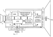
- FIG. 1 is a diagram illustrating a schematic configuration of a camera platform system that is Embodiment 1 of the present invention.
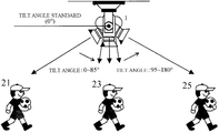
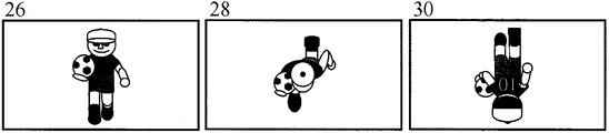
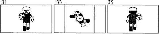
- FIGs. 2A to 2D are diagrams illustrating the relationship of an object, a camera platform system, and a monitor display in Embodiment 1.
- FIGs. 3A and 3B are diagrams of describing a control operation of an image memory in Embodiment 1.
- FIG. 4 is a flowchart of describing the transition of a screen display in Embodiment 1.
- FIG. 5 is a diagram of describing the relationship of a camera platform system and a monitor display rotation angle in Embodiment 1.
- FIG. 6 is a diagram of describing a method of interpolating a pixel in Embodiment 1.
- FIGs. 7A and 7B are diagrams of illustrating a monitor display of an object in Embodiment 2.
- FIGs. 8A to 8C are diagrams of illustrating a monitor display of an object in Embodiment 3.
- FIG. 1 illustrates a configuration of a camera platform system that is Embodiment 1 of the present invention.
- FIGs. 2A to 2D illustrate the relation between the camera platform system and a monitor display image depending upon its tilt angle in Embodiment 1.
- reference numeral 1 denotes a camera platform system configured by a camera which takes an image of an object to generate a shot image and a camera platform by which the camera is capable of performing a pan rotation around a pan axis and a tilt rotation around a tilt axis.
- Reference character PA denotes a pan axis (a second axis)
- reference numeral TA denotes a tilt axis (a first axis).
- the tilt axis TA is an axis that is perpendicular to a vertical direction, and capable of changing a tilt angle of an optical axis of an imaging lens 11 and the tilt angle by the tilt rotation.
- the pan axis PA is an axis that is perpendicular to the tilt axis TA.
- pan rotation means a rotational movement of a camera to move a shot image in a lateral direction
- tilt rotation means a rotational movement of the camera to move the shot image in an upward and downward direction.
- lateral direction and upward and downward direction mean directions in displaying an image.
- the pan rotation and the tilt rotation of camera platform system 1 are controlled by a remote controller that is not shown or by a remote operation through a network such as a LAN.
- An image pickup element 2 such as a CCD sensor or a CMOS sensor.
- the image pickup element 2 performs a photoelectric conversion of the object image to output an imaging signal.
- a GBR separation circuit 3 separates the imaging signal from the image pickup element 2 into color signals of G (green), B (blue), and R (red).
- An image signal processing circuit 4 converts the color signals of G, B, and R (analog signals) into digital signals before performing various kinds of signal processings to the digital signals to generate image signals (hereinafter, referred to as shot images). At least one frame image that constitutes the shot images is temporarily written in an image memory 6.
- An arithmetic processing circuit 5 (hereinafter, referred to as a CPU) performs an address generation control or a timing control of the image memory 6.
- the CPU 5 performs writing and reading controls of the frame image for the image memory 6.
- the image signal processing circuit 4 converts the frame image read from the image memory 6 into a predetermined output form before outputting it from an image output terminal 7 to a monitor that is not shown.
- An image processor is constituted by the image signal processing circuit 4, the CPU 5, and the image memory 6.
- the frame images are sequentially outputted to the monitor to display the output image.
- the output image is an image obtained as a result of the reading control described below for the shot image that is in a state where the camera has taken an image (the frame image written in the image memory 6), and may be the same as the shot image or may be a different image.
- the CPU 5 performs controls of a tilt (T) drive unit (a first drive mechanism) 12 and a pan (P) drive unit 13 (a second drive mechanism), or a control of a zoom (Z) and focus (F) of the imaging lens 11.
- the CPU 5 receives the P/T/Z/F control data sent by a remote controller that is not shown or the like through a communication terminal 8. Then, the CPU 5 outputs the P/T control signal to a P drive unit 13 and a T drive unit 12 in accordance with the control data, and outputs the Z/F control signal to the imaging lens 11.
- the P drive unit 13 and the T drive part 12 perform the pan rotation and the tilt rotation of the camera platform in accordance with the P/T control signal.
- the imaging lens 11 performs the zoom and focus operations in accordance with the Z/F control signal.
- Reference numeral 14 denotes a tilt angle detector, which detects a tilt angle with respect to an installation standard of the camera platform (a ceiling surface in the embodiment) to output the angle data corresponding to the tilt angle to the CPU 5.
- the number of effective pixels of the shot image (the frame image) is assumed to be 1920 in a horizontal direction and 1080 in a vertical direction, and pixel data of G, B, and R is assumed to be 10 bit respectively.
- the sampling is performed at a cycle in which the data of the number of frames needed per second is obtained from the top of the left on the screen, and GBR pixel data equal to or more than one frame is written in the image memory 6 corresponding to the writing address that is generated relating to the number of pixels.
- the width of data is 30 bit.
- the configuration can be changed in accordance with the restriction of the hardware such as the number of effective pixels, a generated address, a data width, and the number of CPUs.
- the camera platform system 1 has a base portion of the P drive unit 13 that is attached to the ceiling to be hung from the ceiling.
- the camera platform system 1 traces moving objects 21, 23, and 25 to perform the tilt rotation and the tilt angle (the tilt angle) is changed from 0 degree to 180 degrees while passing a location immediately under the camera platform system 1 on the way will be described.
- the reading from the image memory 6 is performed in order of the writing, i.e. a sequential reading is performed.
- the output image 26 of the object is displayed on the monitor.
- a (nonrotating) output image that is the same as the shot image like the output image 26 is referred to as a nonrotating image.
- the object is displayed upside down like an image 30 in the sequential reading from the image memory 6. Therefore, specifically, the reading is performed in a direction from a written 1920th pixel of a 1080th line to a first pixel of a first line from, which is opposite to the writing order.
- an output image (a second display image) 35 which corresponds to an image formed by rotating the shot image (the image 30) by 180 degrees around the pan axis, i.e. an image whose top and bottom are reversed is obtained.
- the output image that corresponds to the image rotated by 180 degrees with respect to the shot image like the output image 35 is referred to as a 180-degree rotating image.
- the reading from the image memory 6 is performed so as to obtain the output image (the first display image) 33 which corresponds to the image formed by rotating a shot image (an image 28) around the pan axis by 90 degrees.
- heading 421-pixel data of the 1080th line written in the image memory 6 subsequently 421-pixel data of the 1079th line is read, and finally 1500-pixel data of the first line is read.
- the output image that corresponds to the image that is rotated by 90 degrees with respect to the shot image like the output image 33 is referred to as a 90-degree rotating image.
- the display positions of the 1st to 420th pixels and 1501st to 1920th pixels where pixel data do not exist in the 1st to 1080th lines are set to fixed data such as a black level. Then, valid data read from the image memory 6 are output in a suitable output form such as HD-SDI to output it to the monitor.
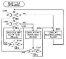
- a flowchart of FIG. 4 illustrates an image display processing (reading control from the image memory 6) in accordance with a detection angle by a tilt angle detector 14 performed by the CPU 5.
- the angle detection by the tilt angle detector 14 and the image display processing in accordance with the detection angle are performed in each frame.
- the CPU 5 determines whether the detection angle by the tilt angle detector 14 is equal to or larger than 85 degrees that is the first set angle in Step S101. It proceeds to Step S102 when the detection angle is equal to or larger than 85 degrees, i.e. in accordance with the arrival of the detection angle to 85 degrees, and on the other hand it proceeds to Step S103 when it is smaller than 85 degrees.
- Step S102 the CPU 5 determines whether the detection angle by the tilt angle detector 14 is equal to or larger than 95 degrees that is the second set angle. It proceeds to Step S105 when the detection angle is equal to or larger than 95 degrees, i.e. in accordance with the arrival of the detection angle to 95 degrees, and on the other hand it proceeds to Step S104 when it is smaller than 95 degrees.
- Step S103 the CPU 5 displays a nonrotating image on the monitor.
- Step S104 the CPU 5 displays a 90-degree rotating image on the monitor.
- Step S105 the CPU 5 displays 180-degree rotating image on the monitor.
- a hysteresis angle of h-degree is set to the first set angle and the second set angle.
- the hysteresis angle of h-degree is an angle set so as to smoothly switch the display image, which is set to an angle smaller than a different between the first set angle and the second set angle.
- the 90-degree rotating image is displayed between the nonrotating image and the 180-degree rotating image.
- the output image corresponding to the image which is formed by rotating the shot image around the pan axis by an angle in a range from 0 degree to 180 degrees other than 90 degrees before and after the 90-degree rotating image may also be displayed between the nonrotating image and the 180-degree rotating image.
- the image can be switched with few senses of incompatibility.
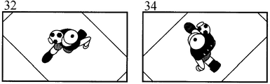
- a 45-degree rotating image 32 corresponding to the image that is formed by rotating the shot image around the pan axis by 45 degrees is displayed between the nonrotating image 31 and the 90 degrees rotating image 33 of FIG. 2C in accordance with a case where the detection angle by the tilt angle detector 14 is 85 degrees.
- a 135-degree rotating image 34 corresponding to the image that is formed by rotating the shot image around the pan axis by 135 degrees is displayed between the 90-degree rotating image 33 and a 180-degree rotating image 35 in accordance with a case where the detection angle is 95 degrees.
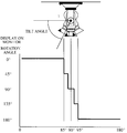
- FIG. 5 illustrates the relation of the tilt angle of the camera platform system 1 in this case and the rotation angle for the shot image outputted on the monitor in this case.
- the hysteresis angle h-degree is omitted.
- the nonrotating image is suddenly switched to the 180-degree rotating image when passing a position immediately under the camera platform system 1.
- the output image in which the rotation angle around the pan axis gradually increases in the vicinity immediately under the camera platform system 1 before displaying the 180-degree rotating image.
- the output image in which the rotation angle around the pan axis is gradually reduced in the vicinity immediately under the camera platform system 1 from the 180-degree rotating image is displayed before displaying the nonrotating image.
- the 45-degree rotating image 32 and the 135-degree rotating image 34 illustrated in FIG. 2D cannot be achieved only by the change of the reading address from the simple image memory 6 described above.
- the 45-degree rotating image 32 and the 135-degree rotating image 34 can be generated by calculating the pixel data at the display pixel position based on an adjacent pixel data value obtained when rotating from data written in the image memory and the distance of pixels to interpolate it.
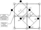
- the image data written in image memory 6 is rotated on the image memory 6 and data of a pixel P which is required at the time of the output from the camera platform system 1 is interpolated to obtain the rotating image around the pan axis centered around a pixel s.
- the pixel data of the pixel P can be obtained by loading these values from the image memory 6 into the CPU 5 and performing the calculation using the following expression by a linear interpolation.
- the distance of pixels is assumed to be 1 (one positive pixel).
- d1 and d2 are distances from the pixel P to the four rotated pixels in two directions orthogonal to each other.
- a non-interlace method is described, but a basic idea of an interlace method is similar to that of the non-interlace method except that a frame processing is inserted.
- the method of the pixel interpolation it is not limited to the method of the four-adjacent pixel interpolation method described as an example, but the interpolation of higher-order by multiple pixels or the data of a front frame may also be used.
- a parallel processing using a plurality of image memories may be performed.
- each angle (45 degrees, 90 degrees, 135 degrees, 180 degrees, 85 degrees, and 95 degrees) and other numerical values in the embodiment described above are merely examples, and other angles or numerical values may also be set.
- the pan axis does not have to be an exact pan axis and the shot image may also be rotated around an axis tilted in a range of 0 to 50 degrees with reference to the exact pan axis, corresponding to the range of 85 to 95 degrees of the tilt angle described above.
- the image may be rotated around any axis if the image is rotated without a sense of incompatibility.
- the rotational central axis is an axis that passes one point in the shot image and that is positioned between an image center and an area where a moving object appears (more preferably, between the image center and a position of the center of gravity of the moving object, or at the position of the center of gravity of the moving object).
- the rotational center the same is applied to the embodiments described blow.
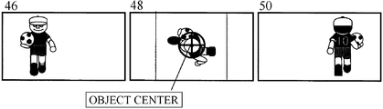
- Embodiment 1 describes the case in which the rotation center of the image around the pan axis is assumed to be a center of the image, but as the output images 41, 43, and 45 illustrated in FIG. 7A, a case in which a moving object does not exist at the image center is also considered.
- a detecting function that detects an area where an object moving in the shot image exists (preferably, a center position of the area) is given to the CPU 5 to be able to obtain the rotating image centered around the area where the object exists as illustrated in FIG. 7B.
- the function to detect the area where the moving object exists can be achieved as follows for example. An amount of movement of the object is calculated based on the difference between the image data of a current frame and a previous frame by the CPU 5. Then, the amount of the movement is compared with an amount of the tilt angle change obtained by the output of the tilt angle detector 14 loaded into the CPU 5 and an area where the amount of the movement is small is determined as the traced moving object to be able to obtain the area of the moving object (furthermore, the center of the area).
- a 90-degree rotating image 48 (furthermore, 45-degree and 135-degree rotating images) is displayed in the vicinity immediately under the camera platform system centered around the area of the moving object obtained above.
- a nonrotating image 46, the 90-degree rotating image 48, and the 180-degree rotating image 50 are sequentially displayed on the monitor.
- Embodiments 1 and 2 described the case in which each rotating image was generated only by the reading control (the image processing) from the image memory 6. However, a more beneficial effect can be achieved by adding the movement of the imaging lens 11.
- the imaging lens 11 performs an optical zoom operation from the previous zoom state to a zoom state at a wide-angle side by the instruction from the CPU 5.
- an effect similar to that of the method of the rotating image generation centered around the object area described in Embodiment 2 can be expected.
- surrounding scenery is also displayed by performing the optical zoom operation at the wide-angle side, performing the rotation processing around the pan axis becomes clearer.
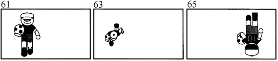
- FIG. 8A illustrates output images 61, 62, and 63 displayed on the monitor when the imaging lens 11 performs only the optical zoom operation (hereinafter, referred to as a lens zoom) to the wide-angle side in the vicinity immediately under the camera platform system 1.
- a lens zoom the optical zoom operation
- Embodiments 1 and 2 a fixed data such as black was displayed in the peripheral range without the image data when the 90-degree rotating image was displayed.
- a 90-degree rotating image 68 where the image exists also in the peripheral range can be displayed by expanding the object (a part of the 90-degree rotating image) in accordance with the size of the object in the nonrotating image 66 or the 180-degree rotating image 70 by the electronic zoom operation.
- the distance between pixels is calculated by the CPU 5 in accordance with the expansion rate as similarly to the pixel data interpolation described in Embodiment 1, and the data of a position required to perform a cut-out display centered around the object is generated based on the4 adjacent pixel data.
- the 90-degree rotating image 68 illustrated in FIG. 8B is an image that is generated by the expansion processing by the electron zoom operation after a part centered around the object of the output image 63 in FIG. 8A is cut out to rotate it by 90 degrees around the pan axis.
- FIG. 8C illustrates the relation of the tilt angle, the expansion rate of the electron zoom, and the lens zoom state in the camera platform system.
- the relation between the lens zoom state and the angle of field may be tabled to be stored in the CPU 5 or may control the zoom magnification so as to obtain the object image of almost the same size by storing the size of the object immediately before the lens zoom operation in the memory.
- the moving velocity of the object may be detected to change the tilt angle for displaying the rotating image or the number of the rotating images that are displayed between the nonrotating image and the 180-degree rotating image in accordance with the moving velocity. If the moving velocity of the object is fast (If it is a second speed that is faster than a first speed), the sense of incompatibility is not easily generated even when the rotating image is displayed from a shallow tilt angle (for example, a tilt angle that is smaller than 85 degrees) or the number of rotating images is reduced. Moreover, if the moving velocity of the object is slow (If it is the first speed), the sense of incompatibility is not easily generated as the number of rotating images in the vicinity immediately under the camera platform system increases.
- the detecting function of the moving velocity of the object can be achieved by the CPU 5 which calculates the moving velocity based on an amount of the change per unit time of the output of the tilt angle detector 14.
- the camera platform system 1 has an operation function of the pan rotation in accordance with the pan instruction signal inputted by the remote control, but the pan instruction signal inputted during the display processing of the rotating image in the vicinity immediately under the camera platform system 1 may also be disregarded. In other words, the pan rotation may not be performed even if the pan instruction signal is inputted. As a result, the delay of the generation processing of the rotating image or the growth of the circuit size for the processing can be prevented.
- the rotating image is generated by using the CPU 5, the image memory 6, and the image signal processing circuit 4 built into the camera platform is described, these may be provided outside the camera platform to generate the rotating image.
- the camera platform system is configured including the CPU, the image memory, and the image signal processing circuit provided outside the camera platform.
- the camera platform system that decreases unnaturalness of the change in a traveling direction of the object in the display image can be provided.
Landscapes
- Engineering & Computer Science (AREA)
- Multimedia (AREA)
- Signal Processing (AREA)
- Physics & Mathematics (AREA)
- General Physics & Mathematics (AREA)
- Studio Devices (AREA)
- Closed-Circuit Television Systems (AREA)
- Accessories Of Cameras (AREA)
- Indication In Cameras, And Counting Of Exposures (AREA)
Priority Applications (6)
| Application Number | Priority Date | Filing Date | Title |
|---|---|---|---|
| RU2012128444/07A RU2520574C2 (ru) | 2010-01-06 | 2010-12-24 | Система операторской платформы |
| DE112010005086T DE112010005086T5 (de) | 2010-01-06 | 2010-12-24 | Kameraplattformsystem |
| CN2010800604054A CN102771121A (zh) | 2010-01-06 | 2010-12-24 | 照相机平台系统 |
| US13/504,145 US9185281B2 (en) | 2010-01-06 | 2010-12-24 | Camera platform system |
| GB1212039.0A GB2489361A (en) | 2010-01-06 | 2010-12-24 | Camera platform system |
| KR1020127017143A KR101339193B1 (ko) | 2010-01-06 | 2010-12-24 | 카메라 플랫폼 시스템 |
Applications Claiming Priority (2)
| Application Number | Priority Date | Filing Date | Title |
|---|---|---|---|
| JP2010000890A JP5235910B2 (ja) | 2010-01-06 | 2010-01-06 | カメラ雲台システム |
| JP2010-000890 | 2010-01-06 |
Publications (1)
| Publication Number | Publication Date |
|---|---|
| WO2011083547A1 true WO2011083547A1 (en) | 2011-07-14 |
Family
ID=44305293
Family Applications (1)
| Application Number | Title | Priority Date | Filing Date |
|---|---|---|---|
| PCT/JP2010/007506 Ceased WO2011083547A1 (en) | 2010-01-06 | 2010-12-24 | Camera platform system |
Country Status (8)
| Country | Link |
|---|---|
| US (1) | US9185281B2 (enExample) |
| JP (1) | JP5235910B2 (enExample) |
| KR (1) | KR101339193B1 (enExample) |
| CN (1) | CN102771121A (enExample) |
| DE (1) | DE112010005086T5 (enExample) |
| GB (1) | GB2489361A (enExample) |
| RU (1) | RU2520574C2 (enExample) |
| WO (1) | WO2011083547A1 (enExample) |
Cited By (3)
| Publication number | Priority date | Publication date | Assignee | Title |
|---|---|---|---|---|
| US20130329067A1 (en) * | 2012-06-12 | 2013-12-12 | Canon Kabushiki Kaisha | Capturing control apparatus, capturing control method and program |
| CN104967827A (zh) * | 2015-07-03 | 2015-10-07 | 北京旷视科技有限公司 | 一种摄像装置及其控制方法 |
| EP3148180A4 (en) * | 2014-06-30 | 2017-07-19 | Huawei Technologies Co. Ltd. | Image processing method and video camera |
Families Citing this family (11)
| Publication number | Priority date | Publication date | Assignee | Title |
|---|---|---|---|---|
| JP5537044B2 (ja) * | 2008-05-30 | 2014-07-02 | キヤノン株式会社 | 画像表示装置及びその制御方法、コンピュータプログラム |
| US20140023343A1 (en) * | 2011-03-25 | 2014-01-23 | Nec Corporation | Video processing system and video processing method, video processing apparatus, control method of the apparatus, and storage medium storing control program of the apparatus |
| JP5987428B2 (ja) * | 2012-04-10 | 2016-09-07 | セイコーエプソン株式会社 | 装置 |
| JP6540948B2 (ja) * | 2015-03-27 | 2019-07-10 | 株式会社富士通ゼネラル | カメラシステム |
| CN104853078B (zh) * | 2015-05-27 | 2020-02-07 | 周毅 | 一种模块式广播级高清摄像机 |
| US10628956B2 (en) * | 2015-09-03 | 2020-04-21 | Sony Corporation | Video processing device, video processing method, and program |
| US10827930B2 (en) * | 2016-02-26 | 2020-11-10 | Niramai Health Analytix Pvt Ltd | Privacy booth for breast cancer screening |
| CN105872339A (zh) * | 2016-05-31 | 2016-08-17 | 广州宝镜智能科技有限公司 | 带有摄像头的终端 |
| JP6994901B2 (ja) * | 2017-10-24 | 2022-01-14 | キヤノン株式会社 | 制御装置、制御方法、及びプログラム |
| CN109496293B (zh) * | 2018-10-12 | 2020-12-04 | 北京小米移动软件有限公司 | 扩展内容显示方法、装置、系统及存储介质 |
| US11849206B1 (en) * | 2022-02-23 | 2023-12-19 | Amazon Technologies, Inc. | Systems and methods for automated object identification and tracking |
Citations (3)
| Publication number | Priority date | Publication date | Assignee | Title |
|---|---|---|---|---|
| JPH10271364A (ja) * | 1997-03-26 | 1998-10-09 | Matsushita Electric Works Ltd | 監視カメラ装置 |
| JP2003289466A (ja) * | 2003-03-27 | 2003-10-10 | Matsushita Electric Ind Co Ltd | カメラ装置 |
| JP2004056239A (ja) * | 2002-07-17 | 2004-02-19 | Kowa Co | 監視カメラ装置 |
Family Cites Families (15)
| Publication number | Priority date | Publication date | Assignee | Title |
|---|---|---|---|---|
| JP2000083188A (ja) * | 1998-09-03 | 2000-03-21 | Matsushita Electric Ind Co Ltd | 監視カメラ装置 |
| JP2000209575A (ja) * | 1999-01-11 | 2000-07-28 | Star Micronics Co Ltd | 監視カメラ装置 |
| JP2001069496A (ja) * | 1999-08-31 | 2001-03-16 | Matsushita Electric Ind Co Ltd | 監視カメラ装置及び監視カメラの制御方法 |
| JP2001086375A (ja) * | 1999-09-09 | 2001-03-30 | Matsushita Electric Ind Co Ltd | 回転台付カメラ |
| US6762755B2 (en) * | 2000-10-16 | 2004-07-13 | Pixel Science, Inc. | Method and apparatus for creating and displaying interactive three dimensional computer images |
| JP4469113B2 (ja) * | 2001-07-10 | 2010-05-26 | ティーオーエー株式会社 | 監視方法及び監視装置 |
| JP3807415B2 (ja) * | 2004-06-25 | 2006-08-09 | 松下電器産業株式会社 | 監視カメラ装置 |
| JP2006352736A (ja) * | 2005-06-20 | 2006-12-28 | Victor Co Of Japan Ltd | 監視カメラ装置 |
| US8279283B2 (en) * | 2005-11-18 | 2012-10-02 | Utc Fire & Security Americas Corporation, Inc. | Methods and systems for operating a video surveillance system |
| JP4977419B2 (ja) | 2006-08-10 | 2012-07-18 | 三洋電機株式会社 | 監視カメラ |
| JP5108323B2 (ja) * | 2007-02-14 | 2012-12-26 | パナソニック株式会社 | 監視カメラ及び監視カメラ制御方法 |
| EP1981263B1 (en) * | 2007-04-13 | 2019-04-03 | Axis AB | Supporting continuous pan rotation in a pan-tilt camera |
| JP5426080B2 (ja) * | 2007-06-19 | 2014-02-26 | 株式会社コナミデジタルエンタテインメント | 走行玩具システム |
| JP5137197B2 (ja) | 2008-06-20 | 2013-02-06 | 万能工業株式会社 | ポジションスイッチ装置 |
| RU83675U1 (ru) * | 2008-10-03 | 2009-06-10 | Закрытое Акционерное Общество "Голлард" | Система видеомониторинга |
-
2010
- 2010-01-06 JP JP2010000890A patent/JP5235910B2/ja active Active
- 2010-12-24 KR KR1020127017143A patent/KR101339193B1/ko not_active Expired - Fee Related
- 2010-12-24 GB GB1212039.0A patent/GB2489361A/en not_active Withdrawn
- 2010-12-24 CN CN2010800604054A patent/CN102771121A/zh active Pending
- 2010-12-24 DE DE112010005086T patent/DE112010005086T5/de not_active Withdrawn
- 2010-12-24 US US13/504,145 patent/US9185281B2/en not_active Expired - Fee Related
- 2010-12-24 RU RU2012128444/07A patent/RU2520574C2/ru not_active IP Right Cessation
- 2010-12-24 WO PCT/JP2010/007506 patent/WO2011083547A1/en not_active Ceased
Patent Citations (3)
| Publication number | Priority date | Publication date | Assignee | Title |
|---|---|---|---|---|
| JPH10271364A (ja) * | 1997-03-26 | 1998-10-09 | Matsushita Electric Works Ltd | 監視カメラ装置 |
| JP2004056239A (ja) * | 2002-07-17 | 2004-02-19 | Kowa Co | 監視カメラ装置 |
| JP2003289466A (ja) * | 2003-03-27 | 2003-10-10 | Matsushita Electric Ind Co Ltd | カメラ装置 |
Cited By (7)
| Publication number | Priority date | Publication date | Assignee | Title |
|---|---|---|---|---|
| US20130329067A1 (en) * | 2012-06-12 | 2013-12-12 | Canon Kabushiki Kaisha | Capturing control apparatus, capturing control method and program |
| CN104380707A (zh) * | 2012-06-12 | 2015-02-25 | 佳能株式会社 | 捕获控制装置、捕获控制方法及程序 |
| US9531935B2 (en) * | 2012-06-12 | 2016-12-27 | Canon Kabushiki Kaisha | Capturing control apparatus, capturing control method and program |
| CN104380707B (zh) * | 2012-06-12 | 2018-01-23 | 佳能株式会社 | 发送装置及其控制方法 |
| EP3148180A4 (en) * | 2014-06-30 | 2017-07-19 | Huawei Technologies Co. Ltd. | Image processing method and video camera |
| US10425608B2 (en) | 2014-06-30 | 2019-09-24 | Huawei Technologies Co., Ltd. | Image processing method and camera |
| CN104967827A (zh) * | 2015-07-03 | 2015-10-07 | 北京旷视科技有限公司 | 一种摄像装置及其控制方法 |
Also Published As
| Publication number | Publication date |
|---|---|
| KR101339193B1 (ko) | 2013-12-10 |
| DE112010005086T5 (de) | 2012-11-15 |
| JP5235910B2 (ja) | 2013-07-10 |
| GB2489361A (en) | 2012-09-26 |
| GB201212039D0 (en) | 2012-08-22 |
| RU2012128444A (ru) | 2014-02-20 |
| KR20120089365A (ko) | 2012-08-09 |
| JP2011142419A (ja) | 2011-07-21 |
| US20120218378A1 (en) | 2012-08-30 |
| CN102771121A (zh) | 2012-11-07 |
| US9185281B2 (en) | 2015-11-10 |
| RU2520574C2 (ru) | 2014-06-27 |
Similar Documents
| Publication | Publication Date | Title |
|---|---|---|
| US9185281B2 (en) | Camera platform system | |
| JP2011142419A5 (enExample) | ||
| JP6821339B2 (ja) | 像振れ補正装置、傾き補正装置、像振れ補正装置の制御方法、傾き補正装置の制御方法 | |
| US7256817B2 (en) | Following device | |
| CN107770433A (zh) | 影像获取装置及其影像平顺缩放方法 | |
| JP4935440B2 (ja) | 画像処理装置およびカメラ装置 | |
| JP2013165487A (ja) | 画像処理装置、撮像装置、およびプログラム | |
| JP2008205796A (ja) | 設置型撮像装置 | |
| JPH1013860A (ja) | 立体画像補間装置及びその方法 | |
| JP2009044475A (ja) | 監視カメラ装置 | |
| JP2012253451A (ja) | 撮像装置及びプログラム | |
| JP5132705B2 (ja) | 画像処理装置 | |
| JP4859795B2 (ja) | カメラ装置及び記録システム | |
| JP6016546B2 (ja) | 撮像装置、その制御方法、および制御プログラム | |
| JP4687748B2 (ja) | 映像処理装置、映像処理方法、プログラム及び記録媒体、並びに映像処理システム | |
| JP6124703B2 (ja) | 撮像装置およびその制御方法 | |
| TWI639338B (zh) | 影像擷取裝置及其影像平順縮放方法 | |
| JP4407530B2 (ja) | 動き検出装置 | |
| JP2792767B2 (ja) | 撮像装置 | |
| US20250088750A1 (en) | Capture control apparatus, capture control method, and image capture system | |
| US9106899B2 (en) | Image pickup apparatus | |
| JP4919165B2 (ja) | 画像合成装置及びプログラム | |
| JP2004207884A (ja) | フレームアウトしない追尾撮影方法 | |
| JP2007134886A (ja) | ビデオカメラシステムおよび撮像ノイズ除去方法 | |
| CN119729192A (zh) | 显示控制装置、显示控制方法、摄像系统、计算机可读介质和计算机程序产品 |
Legal Events
| Date | Code | Title | Description |
|---|---|---|---|
| WWE | Wipo information: entry into national phase |
Ref document number: 201080060405.4 Country of ref document: CN |
|
| 121 | Ep: the epo has been informed by wipo that ep was designated in this application |
Ref document number: 10842067 Country of ref document: EP Kind code of ref document: A1 |
|
| WWE | Wipo information: entry into national phase |
Ref document number: 13504145 Country of ref document: US |
|
| ENP | Entry into the national phase |
Ref document number: 20127017143 Country of ref document: KR Kind code of ref document: A |
|
| ENP | Entry into the national phase |
Ref document number: 1212039 Country of ref document: GB Kind code of ref document: A Free format text: PCT FILING DATE = 20101224 |
|
| WWE | Wipo information: entry into national phase |
Ref document number: 1212039.0 Country of ref document: GB Ref document number: 5978/CHENP/2012 Country of ref document: IN Ref document number: 112010005086 Country of ref document: DE Ref document number: 1120100050864 Country of ref document: DE |
|
| WWE | Wipo information: entry into national phase |
Ref document number: 2012128444 Country of ref document: RU |
|
| 122 | Ep: pct application non-entry in european phase |
Ref document number: 10842067 Country of ref document: EP Kind code of ref document: A1 |
|
| REG | Reference to national code |
Ref country code: BR Ref legal event code: B01A Ref document number: 112012016407 Country of ref document: BR |
|
| ENPC | Correction to former announcement of entry into national phase, pct application did not enter into the national phase |
Ref country code: GB |