WO2011078465A2 - 강도가 개선된 다공성 지지체, 그를 이용한 강화 복합전해질 막, 그 막을 구비한 막-전극 어셈블리 및 연료전지 - Google Patents
강도가 개선된 다공성 지지체, 그를 이용한 강화 복합전해질 막, 그 막을 구비한 막-전극 어셈블리 및 연료전지 Download PDFInfo
- Publication number
- WO2011078465A2 WO2011078465A2 PCT/KR2010/005843 KR2010005843W WO2011078465A2 WO 2011078465 A2 WO2011078465 A2 WO 2011078465A2 KR 2010005843 W KR2010005843 W KR 2010005843W WO 2011078465 A2 WO2011078465 A2 WO 2011078465A2
- Authority
- WO
- WIPO (PCT)
- Prior art keywords
- porous support
- membrane
- electrolyte membrane
- composite electrolyte
- reinforced composite
- Prior art date
- Legal status (The legal status is an assumption and is not a legal conclusion. Google has not performed a legal analysis and makes no representation as to the accuracy of the status listed.)
- Ceased
Links
Images

Classifications
-
- H—ELECTRICITY
- H01—ELECTRIC ELEMENTS
- H01M—PROCESSES OR MEANS, e.g. BATTERIES, FOR THE DIRECT CONVERSION OF CHEMICAL ENERGY INTO ELECTRICAL ENERGY
- H01M8/00—Fuel cells; Manufacture thereof
- H01M8/10—Fuel cells with solid electrolytes
- H01M8/1016—Fuel cells with solid electrolytes characterised by the electrolyte material
- H01M8/1018—Polymeric electrolyte materials
- H01M8/1069—Polymeric electrolyte materials characterised by the manufacturing processes
-
- H—ELECTRICITY
- H01—ELECTRIC ELEMENTS
- H01M—PROCESSES OR MEANS, e.g. BATTERIES, FOR THE DIRECT CONVERSION OF CHEMICAL ENERGY INTO ELECTRICAL ENERGY
- H01M8/00—Fuel cells; Manufacture thereof
- H01M8/02—Details
-
- H—ELECTRICITY
- H01—ELECTRIC ELEMENTS
- H01M—PROCESSES OR MEANS, e.g. BATTERIES, FOR THE DIRECT CONVERSION OF CHEMICAL ENERGY INTO ELECTRICAL ENERGY
- H01M8/00—Fuel cells; Manufacture thereof
- H01M8/02—Details
- H01M8/0289—Means for holding the electrolyte
-
- H—ELECTRICITY
- H01—ELECTRIC ELEMENTS
- H01M—PROCESSES OR MEANS, e.g. BATTERIES, FOR THE DIRECT CONVERSION OF CHEMICAL ENERGY INTO ELECTRICAL ENERGY
- H01M8/00—Fuel cells; Manufacture thereof
- H01M8/10—Fuel cells with solid electrolytes
-
- H—ELECTRICITY
- H01—ELECTRIC ELEMENTS
- H01M—PROCESSES OR MEANS, e.g. BATTERIES, FOR THE DIRECT CONVERSION OF CHEMICAL ENERGY INTO ELECTRICAL ENERGY
- H01M8/00—Fuel cells; Manufacture thereof
- H01M8/10—Fuel cells with solid electrolytes
- H01M8/1016—Fuel cells with solid electrolytes characterised by the electrolyte material
- H01M8/1018—Polymeric electrolyte materials
- H01M8/102—Polymeric electrolyte materials characterised by the chemical structure of the main chain of the ion-conducting polymer
- H01M8/1025—Polymeric electrolyte materials characterised by the chemical structure of the main chain of the ion-conducting polymer having only carbon and oxygen, e.g. polyethers, sulfonated polyetheretherketones [S-PEEK], sulfonated polysaccharides, sulfonated celluloses or sulfonated polyesters
-
- H—ELECTRICITY
- H01—ELECTRIC ELEMENTS
- H01M—PROCESSES OR MEANS, e.g. BATTERIES, FOR THE DIRECT CONVERSION OF CHEMICAL ENERGY INTO ELECTRICAL ENERGY
- H01M8/00—Fuel cells; Manufacture thereof
- H01M8/10—Fuel cells with solid electrolytes
- H01M8/1016—Fuel cells with solid electrolytes characterised by the electrolyte material
- H01M8/1018—Polymeric electrolyte materials
- H01M8/102—Polymeric electrolyte materials characterised by the chemical structure of the main chain of the ion-conducting polymer
- H01M8/1027—Polymeric electrolyte materials characterised by the chemical structure of the main chain of the ion-conducting polymer having carbon, oxygen and other atoms, e.g. sulfonated polyethersulfones [S-PES]
-
- H—ELECTRICITY
- H01—ELECTRIC ELEMENTS
- H01M—PROCESSES OR MEANS, e.g. BATTERIES, FOR THE DIRECT CONVERSION OF CHEMICAL ENERGY INTO ELECTRICAL ENERGY
- H01M8/00—Fuel cells; Manufacture thereof
- H01M8/10—Fuel cells with solid electrolytes
- H01M8/1016—Fuel cells with solid electrolytes characterised by the electrolyte material
- H01M8/1018—Polymeric electrolyte materials
- H01M8/102—Polymeric electrolyte materials characterised by the chemical structure of the main chain of the ion-conducting polymer
- H01M8/1032—Polymeric electrolyte materials characterised by the chemical structure of the main chain of the ion-conducting polymer having sulfur, e.g. sulfonated-polyethersulfones [S-PES]
-
- H—ELECTRICITY
- H01—ELECTRIC ELEMENTS
- H01M—PROCESSES OR MEANS, e.g. BATTERIES, FOR THE DIRECT CONVERSION OF CHEMICAL ENERGY INTO ELECTRICAL ENERGY
- H01M8/00—Fuel cells; Manufacture thereof
- H01M8/10—Fuel cells with solid electrolytes
- H01M8/1016—Fuel cells with solid electrolytes characterised by the electrolyte material
- H01M8/1018—Polymeric electrolyte materials
- H01M8/1041—Polymer electrolyte composites, mixtures or blends
-
- H—ELECTRICITY
- H01—ELECTRIC ELEMENTS
- H01M—PROCESSES OR MEANS, e.g. BATTERIES, FOR THE DIRECT CONVERSION OF CHEMICAL ENERGY INTO ELECTRICAL ENERGY
- H01M8/00—Fuel cells; Manufacture thereof
- H01M8/10—Fuel cells with solid electrolytes
- H01M8/1016—Fuel cells with solid electrolytes characterised by the electrolyte material
- H01M8/1018—Polymeric electrolyte materials
- H01M8/1058—Polymeric electrolyte materials characterised by a porous support having no ion-conducting properties
- H01M8/1062—Polymeric electrolyte materials characterised by a porous support having no ion-conducting properties characterised by the physical properties of the porous support, e.g. its porosity or thickness
-
- H—ELECTRICITY
- H01—ELECTRIC ELEMENTS
- H01M—PROCESSES OR MEANS, e.g. BATTERIES, FOR THE DIRECT CONVERSION OF CHEMICAL ENERGY INTO ELECTRICAL ENERGY
- H01M8/00—Fuel cells; Manufacture thereof
- H01M8/10—Fuel cells with solid electrolytes
- H01M8/1016—Fuel cells with solid electrolytes characterised by the electrolyte material
- H01M8/1018—Polymeric electrolyte materials
- H01M8/1067—Polymeric electrolyte materials characterised by their physical properties, e.g. porosity, ionic conductivity or thickness
-
- Y—GENERAL TAGGING OF NEW TECHNOLOGICAL DEVELOPMENTS; GENERAL TAGGING OF CROSS-SECTIONAL TECHNOLOGIES SPANNING OVER SEVERAL SECTIONS OF THE IPC; TECHNICAL SUBJECTS COVERED BY FORMER USPC CROSS-REFERENCE ART COLLECTIONS [XRACs] AND DIGESTS
- Y02—TECHNOLOGIES OR APPLICATIONS FOR MITIGATION OR ADAPTATION AGAINST CLIMATE CHANGE
- Y02E—REDUCTION OF GREENHOUSE GAS [GHG] EMISSIONS, RELATED TO ENERGY GENERATION, TRANSMISSION OR DISTRIBUTION
- Y02E60/00—Enabling technologies; Technologies with a potential or indirect contribution to GHG emissions mitigation
- Y02E60/30—Hydrogen technology
- Y02E60/50—Fuel cells
-
- Y—GENERAL TAGGING OF NEW TECHNOLOGICAL DEVELOPMENTS; GENERAL TAGGING OF CROSS-SECTIONAL TECHNOLOGIES SPANNING OVER SEVERAL SECTIONS OF THE IPC; TECHNICAL SUBJECTS COVERED BY FORMER USPC CROSS-REFERENCE ART COLLECTIONS [XRACs] AND DIGESTS
- Y02—TECHNOLOGIES OR APPLICATIONS FOR MITIGATION OR ADAPTATION AGAINST CLIMATE CHANGE
- Y02P—CLIMATE CHANGE MITIGATION TECHNOLOGIES IN THE PRODUCTION OR PROCESSING OF GOODS
- Y02P70/00—Climate change mitigation technologies in the production process for final industrial or consumer products
- Y02P70/50—Manufacturing or production processes characterised by the final manufactured product
Definitions
- the present invention relates to a porous support having improved strength, a reinforced composite electrolyte membrane using the same, a membrane-electrode assembly having a reinforced composite electrolyte membrane thereof, and a fuel cell, and more particularly, after the electrospinning, the strength is achieved by introducing heat treatment means or a crosslinking agent. -Impregnated with a hydrogen ion conductive polymer inside the porous support having a high porosity of the polymer material, and improved mechanical strength, electrochemical properties and durability, membrane-electrode assembly equipped with the reinforced composite electrolyte membrane And a fuel cell.
- fuel cells do not require battery replacement or charging, and are fuel cells that supply fuel such as hydrogen or methanol to convert chemical energy into electrical energy during combustion.
- the fuel cell is a high efficiency power generation device with energy conversion efficiency of about 60%. It is more efficient than existing internal combustion engines, so it uses less fuel and is a pollution-free energy source that does not generate environmental pollutants such as SO x , NO x , and VOC. There is an advantage.
- fuel cells have a variety of applications ranging from mobile power supplies for portable devices, transport power supplies for automobiles, and the like to distributed generation available for home and power projects.
- a next-generation transportation device becomes practical, the potential market size is expected to be wide.
- AFC alkaline fuel cells
- PAFC phosphoric acid fuel cells
- MCFC molten carbonate fuel cells
- SOFC solid oxide fuel cells
- PEMFC Polymer electrolyte fuel cells
- DMFC direct methanol fuel cells
- Electrolyte membranes which are key components of polymer electrolyte fuel cells and direct methanol fuel cells, must play a role in preventing fuel from moving from the anode to the cathode, in addition to the basic function as a membrane for hydrogen ion transfer. Therefore, the electrolyte membrane is a cation exchange membrane and must have chemical, thermal, mechanical and electrochemical stability at the same time as the hydrogen ion conductivity.
- ion conductive polymer electrolyte membrane is Nafion, a perfluorine-based hydrogen ion exchange membrane developed by DuPont in the early 1960's.
- Nafion as a commercially available perfluorinated polymer electrolyte membrane, Asahi Chemicals' Aciplex-S membrane, Dow Chemical's Dow membrane and Asahi Glass Flemion membrane of the company.
- the conventional commercially available perfluorinated polymer electrolyte membrane has chemical resistance, oxidation resistance, and excellent ion conductivity, but environmental problems are pointed out due to high price and toxicity of intermediate products produced during manufacturing.
- polymer electrolyte membranes in which carboxyl groups and sulfonic acid groups have been introduced into aromatic ring polymers have been studied.
- sulfonated polyarylether sulfones Journal of Membrane Science , 1993 , 83 , 211
- sulfonated polyether ether ketones Japanese Patent Laid-Open No. Hei 6-93114, US Pat. No. 5,438,082
- Sulfonated polyimide US Pat. No. 6,245,881] and the like are known.
- the known polymer electrolyte membrane is prone to dehydration by acid or heat in the process of introducing sulfonic acid groups into the aromatic ring, and hydrogen ion conductivity is greatly affected by water molecules.
- hydrocarbon polymers such as polyether (ether keton), polysulfone, polyimide, etc., which are relatively inexpensive and have various commercial applications, are available. Research is actively underway.
- the alternative polymer electrolyte membrane having low fuel permeability also has a problem in that it is difficult to realize excellent performance of a polymer electrolyte fuel cell due to a decrease in dimensional stability as well as high water content when hydrating.
- US Patent No. 5,547,551 manufactures a composite membrane in which Nafion solution (5 wt%) is introduced into e-PTFE, and Korean Patent No.746339 has excellent dimensional stability in sulfonated polymers.
- a blend composite film prepared by introducing is disclosed.
- the reinforced composite electrolyte Research on reinforced composite electrolyte membranes is being actively conducted, such as reinforced composite electrolyte membranes marketed under the trade name Gore Select by WL Goore & Associates.
- the reinforced composite electrolyte membrane is determined by the chemical structure, pore size, porosity, and mechanical properties of the porous support employed to impart mechanical properties and dimensional stability, the performance of the final reinforced composite electrolyte membrane is determined. Therefore, since the porous support must have excellent hydrogen ion conductivity characteristics in the reinforced composite electrolyte membrane, high porosity, in particular, high porosity of 70% or more is required.
- Another object of the present invention is to provide a reinforced composite electrolyte membrane impregnated with a hydrogen ion conductive polymer inside the porous support and a method of manufacturing the same.
- the present invention provides a porous support of a polymer material having improved strength by the heat treatment means or cross-linking agent after the electrospinning.
- the porous support of the present invention is selected from the group consisting of polyethylene, polypropylene, polyester, polyamide, cellulose, polysulfone, polyethersulfone, polyimide polyvinylidene fluoride, polyacrylonitrile and polyamideimide, or It consists of a polymer material of two or more mixed forms.
- the strength is improved by the ion crosslinking of 30 to 50% by the crosslinking agent introduced.
- the porosity of the porous support of the present invention meets 20 to 80%.
- the present invention provides a reinforced composite electrolyte membrane impregnated with a hydrogen ion conductive polymer inside a porous support having high porosity and excellent mechanical properties, dimensional stability, and durability.
- the hydrogen ion conductive polymer may be used if it is a sulfonated hydrocarbon-based ion conductor, more preferably sulfonated polysulfone, sulfonated polyether sulfone, sulfonated polyether ketone, sulfonated polyarylene ether
- sulfonated hydrocarbon-based ion conductor more preferably sulfonated polysulfone, sulfonated polyether sulfone, sulfonated polyether ketone, sulfonated polyarylene ether
- One or more selected from the group consisting of sulfones, polyaryletherbenzimidazoles and partially fluorine-introduced ion conductors are used
- the present invention 1) a first step of preparing a reinforced porous support of a polymer material having improved strength by electrospinning the polymer-containing spinning solution, heat treatment or introduction of a crosslinking agent; 2) preparing a polymer electrolyte solution in which a hydrogen ion conductive polymer is dissolved in a polar solvent, and impregnating the porous electrolyte with the polymer electrolyte solution; 3) after the impregnation process, a third step of forming a composite electrolyte membrane by forming a membrane by pressing the rolls by passing through the preheated metal rolls and 4) a fourth step of acid treating the composite electrolyte membrane. It provides a manufacturing method.
- the porous support of the first step is heat treatment is performed for 6 to 12 hours at a temperature of 250 to 350 °C, more preferably 280 to 310 °C after electrospinning.
- the crosslinking agent is selected from the group consisting of divinylbenzene, methylenebisacrylamide and tetramethylene bis acrylamide for the purpose of improving the strength, and thus the crosslinking degree satisfies 30 to 50%. do.
- the material of the porous support of the present invention is selected from the group consisting of polyethylene, polypropylene, polyester, polyamide, cellulose, polysulfone, polyethersulfone, polyimide, polyvinylidene fluoride, polyacrylonitrile and polyamideimide If it is a single or mixed polymer of two or more types can be used. In addition, it is formed by the electrospinning method using a spinning solution in which 10 to 50% by weight of the polymer is dissolved.
- the porosity of the porous support of the present invention meets 20 to 80%.
- the hydrogen ion conductive polymer as the hydrogen ion conductive polymer, sulfonated polysulfone, sulfonated polyether sulfone, sulfonated polyether ketone, sulfonated polyarylene ether sulfone And polyaryletherbenzimidazole and at least one selected from the group consisting of partially fluorine-containing ion conductors.
- the dried film thickness is 1 to 10000 ⁇ m before the acid treatment.
- the present invention provides a membrane-electrode assembly employing a reinforced composite electrolyte membrane having high porosity and excellent mechanical properties, dimensional stability, and durability at the same time, and a fuel cell having the same.
- the present invention is an invention devised from the fact that it is possible to prepare a porous support made of a polymer material having a greatly improved strength by introducing a heat treatment or a crosslinking agent in the form of a nonwoven web formed by electrospinning, and can be applied to electrospinning. It is possible to provide a porous support made of various polymers.
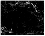
- FIG. 1 is a scanning electron microscope (FE-SEM) photograph before heat treatment of a polyamideimide (PAI) nonwoven fabric used as a porous support in the present invention
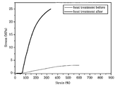
- Figure 3 is a photograph measuring the change in tensile strength before and after heat treatment of the polyamideimide (PAI) nonwoven fabric used as a porous support in the present invention
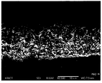
- FIG. 5 is a scanning electron microscope (FE-SEM) photograph of the cross-section of the reinforced composite electrolyte membrane of FIG. 4.
- the present invention provides a porous support having a tensile strength of up to 25 MPa as a porous support of a polymer material having improved strength by introducing heat treatment means or a crosslinking agent after electrospinning.
- FIG. 1 is a surface photograph before heat treatment performed on the porous support of the present invention
- Figure 2 is a surface photograph after heat treatment performed on the porous support of the present invention
- Figure 3 is the result of measuring the change in tensile strength before and after heat treatment.
- porous support of the present invention may be implemented by ion crosslinking, as well as crosslinking by the heat treatment, for the purpose of strength improvement.
- the preferred crosslinking agent may be any one selected from the group consisting of divinylbenzene, methylenebisacrylamide and tetramethylene bis acrylamide, but is not limited thereto.
- crosslinking degree by the crosslinking degree introduction of this invention is preferable. At this time, if the degree of crosslinking is less than 30%, the porous support is dissolved in a solvent and difficult to use. If the crosslinking degree is greater than 50%, flexibility is reduced and brittleness is generated, which is not preferable.
- the present invention may provide various porous supports made of various polymer materials that can be applied to electrospinning.
- the porous support of the present invention is to be used for the purpose of improving the durability, and thus performs a function of improving chemical resistance, oxidation resistance and thermal / mechanical stability.
- Preferred materials for the porous support used for this purpose include polyethylene, polypropylene, polyester, polyamide, cellulose, polysulfone, polyethersulfone, polyimide polyvinylidene fluoride, polyacrylonitrile and polyamideimide Single or mixed forms of two or more selected from the group can be used.
- polyethylene polypropylene
- polyester polyamide
- polyimide polybenzimidazole
- polyamideimide polyamideimide
- the porosity of the porous support is 20 to 80%. If the porosity is less than 20%, a drastic reduction of the hydrogen ion conductivity property occurs, and if it exceeds 80%, the mechanical and chemical resistance or thermal properties Falls out.
- the nonwoven fabric is preferable.
- the nonwoven fabric is described as a preferred embodiment, but is not limited thereto.
- the present invention provides a reinforced composite electrolyte membrane impregnated with a hydrogen ion conductive polymer inside a porous support having improved strength while maintaining the high porosity.
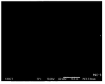
- Figure 4 shows the surface of the reinforced composite electrolyte membrane according to the present invention, while the pores due to the porous support is not observed, showing a dense structure
- Figure 5 is a cross-sectional view of the reinforced composite electrolyte membrane, the porous support is confirmed inside the membrane
- various hydrogen ion conductive polymers that can be impregnated into various porous supports used in the reinforced composite electrolyte membrane of the present invention can be applied, and by applying a known sulfonated hydrocarbon-based ion conductor, high porosity can be maintained.
- the types of hydrogen ion conductive polymer electrolytes that can be used in the reinforced composite electrolyte membrane of the present invention include sulfonated polysulfone, sulfonated poly (ether sulfone), and sulfonated polyether ketone.
- sulfonated poly (ether ketone) sulfonated poly (arylene ether sulfone)
- SPAES poly (arylether benzimidazole)
- partially fluorinated ion conductors One or more ion conductors selected from the group consisting of More preferably sulfonated polyaryleneethersulfone or polyaryletherbenzimidazoles having excellent ion conductivity and thermal / mechanical stability are used.
- the present invention is a first step of preparing a reinforced porous support of a polymer material having improved strength by electrospinning the polymer-containing spinning solution, heat treatment or introduction of a crosslinking agent,
- a method for producing a reinforced composite electrolyte membrane comprising a fourth step of acid treating the composite electrolyte membrane.
- the first step is to prepare a high molecular weight polymer spinning solution having an intrinsic viscosity of 0.4 dL / g or more, and apply the polymer spinning solution to nozzles of various diameters and the spinning distance, apply a high voltage, and conduct electricity onto a collector. Spinning produces a porous support.
- the polymer-containing spinning solution is selected from the group consisting of polyethylene, polypropylene, polyester, polyamide, cellulose, polysulfone, polyethersulfone, polyimide, polyvinylidene fluoride, polyacrylonitrile and polyamideimide 10 to 50% by weight of the solid content of the polymer alone or in combination of two or more thereof is dissolved.
- concentration of the polymer spinning solution of the present invention is less than 10% by weight, a short circuit phenomenon in which the spun fibers are broken is observed. Problems arise.
- the spinning nozzle and the spinning distance to be carried out during the electrospinning can be adjusted, the spinning nozzle of the preferred embodiment can be carried out using a stainless steel tube having a diameter of 0.25mm or 0.42mm, but is not limited thereto.
- the discharge speed may be adjusted according to the spinning nozzle.
- the collector used during the electrospinning is made of an electrically conductive metal plate or a metal mesh, and the shape thereof is not particularly limited, but a circular plate or a rectangular plate is a plate-type collector.
- the size of the plate-shaped collector may vary depending on the viscosity of the polymer solution and the threshold voltage (Vc) accordingly, but is preferably more than the trapping area of the nanofibers produced by spinning from the spinning nozzle.
- the distance between the spinneret and the collector may be adjusted within a range in which the spun fiber is not shorted, preferably 5 to 20 cm, but is not limited thereto.
- Heat treatment in the first step in the production method of the present invention can be prepared in a porous support having excellent mechanical strength by ion crosslinking heat treatment within 250 ⁇ 350 °C, more preferably 6 to 12 hours in the temperature range of 280 ⁇ 310 °C.
- the heat treatment temperature is less than 250 °C, the heat treatment is not sufficiently heat-treated to the inside of the support can not obtain a high strength porous support, there is a disadvantage that takes a long heat treatment time in terms of efficiency.
- the temperature exceeds 350 ° C. the high thermal strain produces non-uniform strength of the support, and due to the rapid increase in strength, the ductility disappears and cracks and fractures occur in the support.
- the crosslinking agent is any one selected from divinylbenzene, methylenebisacrylamide or tetramethylene bis acrylamide, and preferably divinylbenzene is used.
- the crosslinking reaction it may be carried out by adding an initiator selected from N, N'-azobisisobutyronitrile (AIBN), benzoyl peroxide (BPO) or dicumyl peroxide.
- AIBN N, N'-azobisisobutyronitrile
- BPO benzoyl peroxide
- dicumyl peroxide dicumyl peroxide
- the degree of crosslinking by the crosslinking agent may be implemented in 30 to 50% to prepare a porous support having excellent strength.
- the second step is a step of impregnating the porous support with a polymer electrolyte solution in which a hydrogen ion conductive polymer is dissolved in a polar solvent.
- the hydrogen ion conductive polymer to be used may be used if it is a sulfonated hydrocarbon-based ion conductor, preferred examples thereof are sulfonated polysulfone, sulfonated polyether sulfone, sulfonated polyether ketone, sulfonated polyaryl
- One or more selected from the group consisting of eneethersulfones, polyaryletherbenzimidazoles, and partial fluorine-containing ion conductors is used.
- the solvent for dissolving the hydrogen ion conductive polymer is not particularly limited in view of the purpose of the invention, it may be appropriately selected according to the type of the selected hydrogen ion conductive polymer. That is, there is no particular limitation as long as it is a polar solvent as the solvent used for the above purpose, preferably N, N-dimethylacetamide, N-methyl- ⁇ -pyrrolidone, N-methyl-2-pyrrolidone, dimethyl sulfo One or two or more mixed solvents selected from oxides may be used.
- the step of impregnating the porous support is also not particularly limited, and may be any method in which the polymer electrolyte solution in which the hydrogen ion conductive polymer is dissolved is uniformly applied to the porous support.
- Examples thereof include a casting method, a melting method, a roll pressing method, and the like, and preferably, the casting process is performed with a uniform coating thickness when the porous support is impregnated.
- the third step is a step of forming a composite electrolyte membrane by forming a film by squeezing the rolls through the preheated metal rolls after the impregnation step of the second step to form a film.
- a roll pressing method passing through a preheated roll at 120 ° C. for uniform surface and uniform impregnation of the cast film, it is possible to prepare a reinforced composite electrolyte membrane uniformly impregnated due to the remaining trace amount of polar solvent.
- the membrane in order to prevent expansion and contraction of the prepared composite electrolyte membrane, the membrane is fixed in a rectangular frame, and then slowly dried in an inert atmosphere of 40 ° C. to 60 ° C. to prevent the formation of pinholes, and then to 120 ° C. Dry for 3 hours in a reduced pressure drier to completely remove the remaining solvent.
- the thickness of the electrolyte membrane prepared by the above method is preferably 1-10000 ⁇ m before the drying.
- the fourth step in the production method of the present invention is a step of acid treatment of the prepared composite electrolyte membrane
- the acid treatment is an acid (SO 3- H +) capable of hydrogen ion transfer in the sodium salt (SO 3- Na + ) state )
- the acid treatment is carried out under 80 to 120 °C and acid solution conditions for 2 to 3 hours, and is not particularly limited to the type of acid used, sulfuric acid (H 2 SO 4 ), nitric acid (HNO 3 ), phosphoric acid (H It is preferable to select one of strong acids such as 3 PO 4 ), hydrochloric acid (HCl) and the like.
- the present invention provides a membrane-electrode assembly employing the reinforced composite electrolyte membrane and a fuel cell provided with the membrane-electrode assembly.
- acyl halide such as thionyl chloride is dissolved in a polar solvent such as 1-methyl-2-pyrrolidinone (NMP, NMP), cooled to 5 ° C or lower, and then prepared at a room temperature.
- NMP 1-methyl-2-pyrrolidinone
- Aromatic tricarboxylic acid anhydride is added and stirred at room temperature within 1 hour, continuously adding aromatic diamine and reacting at 50-130 ° C. for 5 hours or less, intrinsic viscosity (solvent: DMAc, temperature: 30 ° C., concentration 0.5 g) / dL) was polymerized with a PAI resin of 0.4 dL / g or less.
- TPP triphenylphosphite
- the prepared PAI polymer was prepared in a polymer spinning solution at a concentration of 10% by weight on a polar solvent DMAc, and the polymer spinning solution was electrospun onto a collector through a nozzle having a diameter of 0.25 mm under a voltage of 15 kV and a spinning distance of 10 cm. Thereafter, the PAI fiber web electrospun on the collector was separated to prepare a porous support of PAI material in the form of a nonwoven fabric.
- the PAI porous support was heat-treated for 12 hours at a temperature range of 280 ⁇ 310 °C of the high temperature dryer.
- PAI TORLON 4000T
- SOLVAY SOLEXIS which is a powder state produced by SOLVAY SOLEXIS
- Step 1 preparation of sulfonated polyarylene ether sulfone copolymer having a sulfonation degree of 50%
- reaction solution was diluted with NMP, filtered, poured into water, precipitated in the form of swollen fibers, and filtered. Thereafter, the obtained reaction product was dried in a vacuum dryer at 120 ° C. for 24 hours to obtain a sulfonated polyarylene ether sulfone (SPAES-50), which is a sulfonated polymer copolymer.
- SPAES-50 sulfonated polyarylene ether sulfone
- SPAES sulfonated polyarylene ether sulfone copolymer prepared in step 1 having a degree of sulfonation degree of 50% in N-methyl-2-pyrrolidone (NMP) at 80 ° C.
- NMP N-methyl-2-pyrrolidone
- the prepared composite electrolyte membrane is in the form of sodium salt (SO 3- Na + ), 0.5 mole of sulfuric acid (H 2) at 100 ° C. for the purpose of completely converting to a form of acid (SO 3 -H + ) capable of hydrogen ion transfer.
- SO 4 After the acid treatment for 2 hours in the solution to remove the residual acid after washing for 2 hours or more in a third distilled water of 100 °C repeated washing several times to prepare a reinforced composite electrolyte membrane.
- a nonwoven fabric of PAI material prepared in Example 1 was used as a crosslinking agent. After immersion, the reaction was carried out at 80 to 120 ° C. for 30 minutes to 12 hours, followed by repeated washing several times at 60 ° C. using ethanol to remove residual DVB, and having a porosity of 30% through ionic crosslinking.
- the support was prepared.
- SPAES polyarylene ether sulfone copolymer having a level of degree of sulfonation of 50% prepared in step 1 of Example 2 was dissolved in N-methyl-2-pyrrolidone (NMP). After filtering, the resultant was filtered using a 0.45 ⁇ m pore size PTFE syringe filter and poured directly onto a clean glass plate without surface scratches. The solvent used in the preparation of the casting solution was slowly dried in an inert atmosphere at 60 ° C., and then dried in a reduced pressure dryer at 100 ° C. for 3 hours or more to completely remove the solvent, thereby preparing an electrolyte membrane having a thickness of 50 ⁇ m. After the preparation was carried out in the same manner as the acid treatment of step 2 of Example 2 above.
- NMP N-methyl-2-pyrrolidone
- Nafion TM 115 (US Dupont) was commercialized by removing impurities with 3% hydrogen peroxide, followed by washing for 2 hours in 0.5M sulfuric acid, and then washing in tertiary distilled water several times.
- FIG. 1 is a scanning electron microscope (FE-SEM) result before heat treatment of a polyamideimide (PAI) nonwoven fabric used as a porous support of the reinforced composite electrolyte membrane of the present invention
- Figure 2 is a scanning electron microscope (FE-SEM) after heat treatment It is a result of comparing the results
- Figure 3 shows the results of the change in tensile strength of the polyamideimide (PAI) nonwoven fabric before and after heat treatment.
- the porous support significantly increased the mechanical strength after the heat treatment process.
- SPAES sulfonated polyarylene ether sulfone copolymer
- FE-SEM scanning electron microscopy
- Figure 5 shows the cross-section of the reinforced composite electrolyte membrane, by confirming the porous support structure inside the membrane, to support the mechanical strength improvement.
- the electrolyte membranes prepared in Example 2, Comparative Example 1 and Comparative Example 2 were washed several times with deionized water, and the washed polymer electrolyte membrane was immersed in deionized water for 24 hours. After removing and removing the water present on the surface was weighed (W wet ). The same membrane was then again dried for 24 hours in a reduced pressure dryer at 120 ° C. and again weighed (W dry ). The water absorption was calculated by the following equation .
- R is the measurement resistance ( ⁇ )
- L is the length (cm) between the measurement electrodes
- A is the cross-sectional area (cm 2) of the prepared electrolyte membrane.
- Methanol permeability (methanol permeability) was installed by the electrolyte membrane between a constant concentration of methanol and water, and the concentration of methanol over time was measured by the refractive index detector (refractiv index dector, R1750F Younglin instrument) was calculated by the following equation (4 ).
- a is the slope in the time-concentration graph
- V B is the volume of permeated methanol (cm 3)
- L is the thickness of the electrolyte membrane (cm)
- A is the area of the electrolyte membrane (cm 2)
- C A is used. Shows the concentration of methanol.
- Table 1 shows the results of evaluating the properties of the fuel cell reinforced composite electrolyte membrane.
- the water absorption rate was reduced to less than half as compared to the polymer electrolyte membrane (Comparative Example 1) consisting of only sulfonated polyarylene ether sulfone (SPAES) copolymer, and the comparative example Compared to 1 and commercial electrolyte membrane (Comparative Example 3), similar levels of hydrogen ion conductivity were shown.
- SPAES polyarylene ether sulfone
- the reinforced composite electrolyte membrane of the present invention was compared with a polymer electrolyte membrane composed of only sulfonated polyarylene ether sulfone (SPAES) copolymer (Comparative Example 1) as a result of comparing hydrogen ion conductivity and membrane resistance, and hydrogen ion conductivity. Due to the porous support without, the hydrogen ion conductivity was somewhat reduced, but the actual membrane resistance considering the thickness of the sulfonated polyarylene ether could be significantly lowered due to the excellent mechanical strength of the reinforced composite electrolyte membrane of the present invention. It can be controlled to an equivalent level or higher than a polymer electrolyte membrane made of a sulfone (SPAES) copolymer.
- SPAES sulfone
- Example 2 showed much lower 5.25 ⁇ 10 ⁇ 7 cm 2 / s as compared to the 1.65 ⁇ 10 ⁇ 6 cm 2 / s result for the commercialized Nafion 115 (Comparative Example 2). Therefore, it was confirmed that the reinforced composite electrolyte membrane of the present invention lowered methanol permeability and improved methanol permeation characteristics.
- the present invention provides a reinforced composite electrolyte membrane in which a hydrogen ion conductive polymer is impregnated into a porous support whose strength is improved by heat treatment or crosslinking agent after electrospinning, thereby providing a polymer electrolyte composed of only a conventional hydrogen ion conductive polymer.
- the membrane Compared to the membrane, the dimensional stability, water absorption rate and methanol permeability are improved, so that it can be applied as an electrolyte membrane for fuel cells or polymer electrolyte fuel cells and direct methanol fuel cells.
Landscapes
- Chemical & Material Sciences (AREA)
- Engineering & Computer Science (AREA)
- Manufacturing & Machinery (AREA)
- Chemical Kinetics & Catalysis (AREA)
- Sustainable Energy (AREA)
- Sustainable Development (AREA)
- Life Sciences & Earth Sciences (AREA)
- Electrochemistry (AREA)
- General Chemical & Material Sciences (AREA)
- Crystallography & Structural Chemistry (AREA)
- Composite Materials (AREA)
- Fuel Cell (AREA)
- Manufacture Of Macromolecular Shaped Articles (AREA)
Abstract
본 발명은 강도가 개선된 다공성 지지체, 그를 이용한 강화 복합전해질 막 및 그 막을 구비한 막-전극 어셈블리 및 연료전지에 관한 것이다. 본 발명의 다공성 지지체는 전기방사 이후, 열처리 수단 또는 가교제의 도입 에 의해 비약적으로 기계적 강도가 개선된 다공성 지지체로서, 전기방사에 적용되는 다양한 고분자 재질의 다공성 지지체를 제공할 수 있으며, 상기 다공성 지지체 내부에 수소이온 전도성 고분자가 함침되어 제조된 강화 복합전해질 막을 제공할 수 있다. 이에, 본 발명의 강화 복합전해질 막은 높은 기공도를 유지하면서도 기계적 강도, 전기화학적 특성 및 내구성이 개선되므로 이를 채용한 막-전극 어셈블리 및 연료전지의 성능을 향상시킬 수 있다.
Description
본 발명은 강도가 개선된 다공성 지지체, 그를 이용한 강화 복합전해질 막, 그 강화 복합전해질 막을 구비한 막-전극 어셈블리 및 연료전지에 관한 것으로서, 더욱 상세하게는 전기방사 이후, 열처리 수단 또는 가교제 도입으로 강도가 개선된 높은 기공도를 가지는 고분자 재질의 다공성 지지체 내부에 수소이온 전도성 고분자가 함침되어, 기계적 강도, 전기화학적 특성 및 내구성이 개선된 강화 복합전해질 막, 그 강화 복합전해질 막이 구비된 막-전극 어셈블리 및 연료전지에 관한 것이다.
연료전지는 일반 전지와는 달리, 전지의 교환이나 충전이 불필요할 뿐 아니라, 수소나 메탄올 등의 연료를 공급하여 연소 시, 화학에너지를 전기에너지로 변환시키는 발전형 전지이다.
연료전지는 에너지 변환효율이 60%정도의 고효율 발전장치로서, 기존 내연기관에 비하여 효율이 높아 연료 사용량이 적으며, SOx, NOx, VOC 등의 환경오염 물질을 발생시키지 않는 무공해 에너지원이라는 장점이 있다.
또한, 생산을 위해 다양한 원료가 사용 가능하고, 생산설비에 필요한 입지면적이 적고 건설 기간이 짧다는 등의 추가적 장점이 있다. 따라서, 연료전지는 휴대용 기기 등의 이동용 전원, 자동차 등의 수송용 전원, 가정용 및 전력사업용으로 이용 가능한 분산형 발전에 이르기까지 응용분야가 다양하다. 특히, 차세대 운송장치인 연료전지 자동차의 운영이 실용화될 경우, 그 잠재 시장규모는 광범위할 것으로 예상된다.
연료전지는 작동되는 온도와 전해질에 따라 크게 5가지로 분류되는데, 상세하게는 알칼리 연료전지(AFC), 인산형 연료전지(PAFC), 용융 탄산염형 연료전지(MCFC), 고체 산화물 연료전지(SOFC), 고분자 전해질 연료전지(PEMFC) 및 직접메탄올 연료전지(DMFC)가 있다. 그 중에서, 이동성이 우수한 고분자 전해질 연료전지 및 직접 메탄올 연료전지가 미래 전원으로서 큰 주목을 받고 있다.
고분자 전해질 연료전지 및 직접 메탄올 연료전지의 핵심 구성 요소인 전해질 막은 수소이온 전달을 위한 막으로서의 기본 기능 이외에도, 연료가 양극에서 음극으로 이동하는 것을 막는 역할을 수행하여야 한다. 따라서, 전해질 막은 양이온교환 막으로서, 수소이온 전도성과 동시에 화학적, 열적, 기계적 및 전기화학적 안정성이 구비해야 한다.
이온 전도성 고분자 전해질 막의 대표적인 예로는 1960년대 초 미국 듀폰사에서 개발한 과불소계 수소이온 교환막인 나피온(Nafion)을 들 수 있다. 나피온 이외에도 이와 유사한 과불소계 고분자 전해질 상용막으로서, 아사히케미칼스(Asahi Chemicals)사의 아시플렉스-에스(Aciplex-S)막, 다우 케미칼스(DowChemicals)사의 다우(Dow)막, 아사히 글래스(Asahi Glass)사의 프레미온(Flemion)막 등이 있다.
그러나, 종래 상용화된 과불소계 고분자 전해질 막은 내화학성, 내산화성, 우수한 이온 전도성을 가지고 있으나, 높은 가격과 제조시 발생하는 중간생성물의 독성으로 인한 환경 문제가 지적되고 있다.
따라서, 이러한 과불소계 고분자 전해질 막의 결점을 보완하기 위하여 방향족환 고분자에 카르복실기, 술폰산기 등을 도입한 고분자 전해질 막이 연구되고 있으며, 그 일례로 술폰화된 폴리아릴에테르 술폰[Journal of Membrane Science, 1993, 83, 211], 술폰화된 폴리에테르에테르 케톤[일본 특허공개공보 제평6-93114호, 미국특허 제5,438,082호], 술폰화된 폴리이미드[미국특허 제6,245,881호]등이 공지되어 있다. 그러나, 상기 공지의 고분자 전해질 막은 방향족 환상에 술폰산기를 도입하는 과정에서 산 또는 열에 의한 탈수반응이 일어나기 쉽고, 수소이온 전도성이 물분자에 크게 영향을 받는 단점을 보인다.
이외에도 상기 언급한 과불소계 및 탄화수소계 고분자 전해질 막은 100℃이상에서 함수율 감소로 인한 수소이온 전도도의 급격한 감소 및 막의 연화, 높은 메탄올 투과도 등의 문제로 인하여 연료전지 상용화에 큰 한계에 부딪히고 있다. 이러한 문제점을 해소하기 위한 방법으로, 가격이 상대적으로 저렴하며 상업적으로 다양하게 응용이 가능한 폴리에테르케톤(polyether(ether keton)), 폴리술폰(polysulfone), 폴리이미드(polyimide) 등의 탄화수소계 고분자에 대한 연구가 활발히 진행 중이다.
그러나 연료의 투과도가 낮은 상기의 대체 고분자 전해질 막도 수화시, 함수량이 높아 치수 안정성이 떨어질 뿐만 아니라 기계적 물성 저하로 인하여 고분자 전해질 연료전지의 우수한 성능을 구현하기 어려운 문제점이 있다.
따라서, 연료전지의 향상된 셀 성능을 얻기 위해서는 이들 대체 전해질 막의 수화에 따른 치수 안정성 및 기계적 물성이 우수한 새로운 물질이 절실히 요구된다.
이러한 요구에 따라 진행된 종래기술로서, 미국특허 제 5,547,551호에서는 나피온 용액(5wt%)을 e-PTFE에 도입하는 복합막을 제조하고, 대한민국특허 제746339호에서는 술폰화된 고분자에 치수안정성이 우수한 고분자를 도입하여 제조되는 블렌드 복합막을 개시하고 있다.
또한, 상기 탄화수소계 고분자의 가장 큰 단점인 내산화성과 열적 기계적 안정성을 개선시키고, 막 전극 접합체(MEA) 제조시에 과도한 팽윤에 의하여 발생하는 전극의 낮은 접합성을 극복하기 위한 노력으로, 강화 복합 전해질막(reinforced composite electrolyte membranes)에 관한 연구가 활발히 진행되고 있는 바, 고어 앤 어소시에이트(W.L. Goore & Associates)사에서 고어셀렉트(Gore Select)라는 상품명으로 출시되고 있는 강화복합 전해질 막이 대표적이다.
일반적으로 강화 복합전해질 막은 기계적 물성 및 치수 안정성을 부여하기 위하여 채용된 다공성 지지체의 화학구조, 기공크기, 기공도 및 기계적 물성에 따라, 최종 강화 복합전해질 막의 성능이 결정된다. 따라서 다공성 지지체는 강화 복합전해질 막에 우수한 수소이온 전도도 특성을 가져야 하므로, 높은 기공도 특히, 70% 이상의 높은 기공도가 요구된다.
그러나, 높은 기공도를 가질 경우 기계적 물성이 저하되는 문제점을 보이므로, 높은 기공도를 유지하면서도 우수한 기계적 물성, 치수안정성, 내구성 을 동시에 구비한 다공성 지지체 및 이온전도체 개발이 절실히 요구된다.
본 발명의 목적은 높은 기공도를 유지하면서도 강도가 개선된 다공성 지지체를 제공하는 것이다.
본 발명의 다른 목적은 상기 다공성 지지체 내부에 수소이온 전도성 고분자가 함침된 강화 복합전해질 막 및 그 제조방법을 제공하는 것이다.
본 발명의 다른 목적은 높은 기공도를 가지면서 우수한 기계적 물성, 치수안정성, 내구성의 강화 복합전해질 막이 구비된 막-전극 어셈블리 및 연료전지를 제공하는 것이다.
상기 목적을 달성하기 위하여, 본 발명은 전기방사 후, 열처리 수단 또는 가교제 도입에 의해 강도가 개선된 고분자 재질의 다공성 지지체를 제공한다.
본 발명의 다공성 지지체는 폴리에틸렌, 폴리프로필렌, 폴리에스테르, 폴리아미드, 셀룰로오스, 폴리술폰, 폴리에테르술폰, 폴리이미드 폴리비닐리덴플로라이드, 폴리아크릴로니트릴 및 폴리아미드이미드로 이루어진 군에서 선택되는 단독 또는 2종 이상의 혼합 형태의 고분자 재질로 이루어진다.
본 발명의 다공성 지지체는 가교제 도입에 의한 가교도가 30 내지 50%의 이온가교로 강도가 개선되는 것이다.
또한, 본 발명의 다공성 지지체의 기공률이 20 내지 80%를 충족한다.
본 발명은 높은 기공도를 가지면서 우수한 기계적물성, 치수안정성, 내구성을 갖춘 다공성 지지체 내부에 수소이온 전도성 고분자가 함침된 강화 복합전해질 막을 제공한다. 이때, 수소이온 전도성 고분자는 술폰화된 탄화수소계 이온전도체이면 사용 가능하고, 더욱 바람직하게는 술폰화된 폴리술폰, 술폰화된 폴리에테르술폰, 술폰화된 폴리에테르케톤, 술폰화된 폴리아릴렌에테르술폰, 폴리아릴에테르벤즈이미다졸 및 부분불소가 도입된 이온전도체로 구성된 그룹으로부터 선택되는 하나 이상인 것을 사용한다.
본 발명은 1) 고분자함유 방사용액을 전기방사 이후, 열처리처리 또는 가교제 도입에 의해 강도를 개선시킨 고분자 재질의 강화 다공성 지지체를 준비하는 제1공정; 2) 수소이온 전도성 고분자가 극성용매에 용해된 고분자 전해질 용액을 제조하고, 상기 다공성 지지체에 상기 고분자 전해질 용액을 함침시키는 제2공정; 3) 상기 함침공정 이후, 예열된 금속롤 사이를 통과하여 롤 압착하여 막 형태로 성형하여 복합전해질 막을 형성하는 제3공정 및 4) 상기 복합 전해질 막을 산처리하는 제4공정으로 이루어진 강화 복합전해질 막의 제조방법을 제공한다.
이때, 제1공정의 다공성 지지체는 전기방사 후, 250 내지 350℃, 더욱 바람직하게는 280 내지 310℃ 온도에서 6 시간 내지 12시간동안 열처리가 수행되는 것이다.
또한, 제1공정에는 강도개선을 위한 목적으로 가교제는 디비닐벤젠, 메틸렌비스아크릴아마이드 및 테트라메틸렌 비스 아크릴아미드로 이루어진 군에서 선택되는 어느 하나가 사용되며, 그로 인한 가교도가 30 내지 50%를 충족한다.
본 발명의 다공성 지지체의 재질은 폴리에틸렌, 폴리프로필렌, 폴리에스테르, 폴리아미드, 셀룰로오스, 폴리술폰, 폴리에테르술폰, 폴리이미드, 폴리비닐리덴플로라이드, 폴리아크릴로니트릴 및 폴리아미드이미드로 이루어진 군에서 선택되는 단독 또는 2종 이상의 혼합 형태의 고분자라면 사용가능하다. 또한, 상기 고분자 10 내지 50중량%가 용해된 방사용액을 이용하여 전기방사법에 의해 형성되는 것이다.
본 발명의 다공성 지지체의 기공률은 20 내지 80%를 충족한다.
본 발명의 강화 복합전해질 막의 제조방법 중 제2공정에 수소이온 전도성 고분자로서 바람직하게는 술폰화된 폴리술폰, 술폰화된 폴리에테르술폰, 술폰화된 폴리에테르케톤, 술폰화된 폴리아릴렌에테르술폰, 폴리아릴에테르벤즈이미다졸 및 부분불소가 도입된 이온전도체로 구성된 그룹으로부터 선택되는 하나 이상이면 사용 가능하다.
본 발명의 강화 복합전해질 막의 제조방법 중 제3공정에서, 산처리 전, 건조된 막 두께가 1∼10000㎛인 것이다.
나아가, 본 발명은 높은 기공도를 가지면서 우수한 기계적물성, 치수안정성, 내구성을 동시에 갖춘 강화 복합전해질 막이 채용된 막-전극 접합체 및 이를 구비한 연료전지를 제공한다.
본 발명에 따라, 전기방사 이후, 열처리 수단 또는 가교제 도입에 의해 강도가 개선된 고분자 재질의 다공성 지지체를 제공할 수 있다.
특히, 본 발명은 전기방사에 의해 형성된 부직포 웹 형태를 열처리 또는 가교제를 도입함으로써, 비약적으로 강도가 개선된 고분자 재질의 다공성 지지체를 제조할 수 있다는 점으로부터 안출된 발명으로서, 전기방사에 적용될 수 있는 다양한 고분자로 이루어진 다공성 지지체를 제공할 수 있다.
또한, 상기 다공성 지지체 내부에 수소이온 전도성 고분자가 함침된 강화 복합전해질 막을 제공할 수 있다.
나아가, 본 발명의 강화 복합전해질 막을 구비한 막-전극 접합체 및 연료전지의 성능향상을 기대할 수 있다.
도 1은 본 발명에서 다공성 지지체로 사용된 폴리아미드이미드(PAI) 부직포의 열처리 전, 주사 전자현미경(FE-SEM) 사진이고,
도 2는 본 발명에서 다공성 지지체로 사용된 폴리아미드이미드(PAI) 부직포의 열처리 후, 주사 전자현미경(FE-SEM) 사진이고,
도 3은 본 발명에서 다공성 지지체로 사용된 폴리아미드이미드(PAI) 부직포의 열처리 전후의 인장강도 변화를 측정한 사진이고,
도 4는 본 발명에 따른 강화 복합전해질 막 표면의 주사 전자현미경(FE-SEM) 사진이고,
도 5는 도 4의 강화 복합전해질 막 단면의 주사 전자현미경(FE-SEM) 사진이다.
이하, 본 발명을 상세히 설명하고자 한다.
본 발명은 전기방사 이후, 열처리 수단 또는 가교제 도입에 의해 강도가 개선된 고분자 재질의 다공성 지지체로서, 더욱 상세하게는 최대 25MPa의 인장강도가 확보된 다공성 지지체를 제공한다.
도 1은 본 발명의 다공성 지지체에 열처리 수행 이전의 표면사진이고, 도 2는 본 발명의 다공성 지지체에 열처리 수행 이후의 표면사진이며, 도 3은 열처리 전후의 인장강도변화를 측정한 결과이다. 상기로부터 본 발명의 고분자 재질의 다공성 지지체는 전기방사 이후 열처리 수단에 의해, 비약적으로 기계적 강도의 개선을 수반한다.
또한, 본 발명의 다공성 지지체는 강도개선 목적으로 상기 열처리에 의한 가교뿐만 아니라, 가교제를 도입한 이온가교에 의해 구현될 수 있다. 이때, 바람직한 가교제로는 디비닐벤젠, 메틸렌비스아크릴아마이드 및 테트라메틸렌 비스 아크릴아미드로 이루어진 군에서 선택되는 어느 하나를 사용할 수 있으나, 이에 한정되는 것은 아닐 것이다.
본 발명의 가교도 도입에 의한 가교도가 30 내지 50%가 바람직하다. 이때, 가교도가 30% 미만이면, 다공성 지지체가 용매에 용해되어 사용이 어렵고, 50%를 초과하면, 유연성(flexibility)이 감소하여 잘 깨지는 문제(brittle)가 발생하여 바람직하지 않다.
따라서, 본 발명은 전기방사에 적용될 수 있는 다양한 고분자 소재로 이루어진 다양한 다공성 지지체를 제공할 수 있을 것이다.
이에, 본 발명의 다공성 지지체는 내구성 향상을 목적으로 사용되기 위한 모체가 되므로 내화학성, 내산화성 및 열적/기계적 안정성을 향상시켜주는 기능을 수행한다. 상기 목적으로 사용하는 다공성 지지체의 바람직한 재질로는 폴리에틸렌, 폴리프로필렌, 폴리에스테르, 폴리아미드, 셀룰로오스, 폴리술폰, 폴리에테르술폰, 폴리이미드 폴리비닐리덴플로라이드, 폴리아크릴로니트릴 및 폴리아미드이미드로부터 이루어진 군에서 선택되는 단독 또는 2종 이상의 혼합 형태가 사용될 수 있다.
상기 중에서, 더욱 바람직하게는 내화학성, 내산화성 및 열적/기계적 안정성이 뛰어난 폴리에틸렌, 폴리프로필렌, 폴리에스테르, 폴리아미드, 폴리이미드, 폴리벤즈이미다졸 및 폴리아미드이미드로 선택되는 단독 또는 2종이상의 혼합 형태의 소재를 사용하는 것이다.
상기 다공성 지지체의 기공률은 20 내지 80%인 것이 바람직하며, 기공률이 20% 미만이면, 급격한 수소이온 전도도 특성의 감소를 초래하며, 80%를 초과하면, 기계적 특성과 내화학적 특성 또는 열적 특성이 나빠진다.
한편, 상기 지지체의 형태에 있어서는 기공형태, 부직포 형태 등이 가능하나, 이온전도체의 균일 함침 및 그에 따른 이온전도특성 등을 감안할 때 부직포 형태인 것이 바람직하다. 이에, 본 발명의 실시예에서는 부직포 형태를 바람직한 실시형태로 설명하고 있으나, 이에 한정되는 것은 아니다.
본 발명은 상기 높은 기공도를 유지하면서도 강도가 개선된 다공성 지지체 내부에 수소이온 전도성 고분자가 함침된 강화 복합전해질 막을 제공한다.
도 4는 본 발명에 따른 강화 복합전해질 막 표면을 도시한 것으로서, 다공성 지지체로 인한 기공이 관찰되지 않고 치밀한 조직을 보이는 반면, 도 5는 상기 강화 복합전해질 막의 단면으로서, 막 내부에 다공성 지지체가 확인됨으로써, 우수한 기계적 강도결과가 뒷받침될 것이다. 이때, 본 발명의 강화 복합전해질 막에 사용되는 다양한 다공성 지지체 내부에 함침할 수 있는 다양한 수소이온 전도성 고분자를 적용할 수 있으며, 공지의 술폰화된 탄화수소계 이온전도체를 적용함으로써, 높은 기공도를 유지하면서도 기계적 물성과 치수안정성이 확보된 다양한 형태의 강화 복합전해질 막을 제공할 수 있다.
본 발명의 강화 복합전해질 막에서 사용될 수 있는 수소이온 전도성 고분자 전해질의 종류에는 술폰화된 폴리술폰(sulfonated polysulfone), 술폰화된 폴리에테르술폰(sulfonated poly(ether sulfone)), 술폰화된 폴리에테르케톤(sulfonated poly(ether ketone)), 술폰화된 폴리아릴렌에테르술폰(sulfonated poly(arylene ether sulfone), SPAES), 폴리아릴에테르벤즈이미다졸(poly(arylether benzimidazole)) 및 부분불소가 도입된 이온전도체로 구성된 그룹으로부터 선택되는 하나 이상의 이온전도체가 사용된다. 더욱 바람직하게는 이온전도성과 열적/기계적 안정성이 뛰어난 술폰화된 폴리아릴렌에테르술폰 또는 폴리아릴에테르벤즈이미다졸이 사용된다.
또한, 본 발명은 고분자함유 방사용액을 전기방사 이후, 열처리처리 또는 가교제 도입에 의해 강도를 개선시킨 고분자 재질의 강화 다공성 지지체를 준비하는 제1공정,
수소이온 전도성 고분자가 극성용매에 용해된 고분자 전해질 용액을 제조하고, 상기 다공성 지지체에 상기 고분자 전해질 용액을 함침시키는 제2공정,
상기 함침공정 이후, 예열된 금속롤 사이를 통과하여 롤 압착하여 막 형태로 성형하여 복합전해질 막을 형성하는 제3공정 및
상기 복합 전해질 막을 산처리하는 제4공정으로 이루어진 강화 복합전해질 막의 제조방법을 제공한다.
본 발명의 제조방법에서 제1공정은 고유점도가 0.4 dL/g 이상의 고분자량의 고분자 방사용액을 제조하고, 고분자 방사용액을 다양한 직경의 노즐과 방사거리를 조절하고 고전압을 인가하고 컬렉터 상으로 전기방사하여 다공성 지지체를 제조한다.
이때, 고분자함유 방사용액은 폴리에틸렌, 폴리프로필렌, 폴리에스테르, 폴리아미드, 셀룰로오스, 폴리술폰, 폴리에테르술폰, 폴리이미드, 폴리비닐리덴플로라이드, 폴리아크릴로니트릴 및 폴리아미드이미드로 이루어진 군에서 선택되는 단독 또는 2종 이상의 혼합 형태의 고분자의 고형분함량이 10 내지 50중량%가 용해된 것이다. 이때, 본 발명의 고분자 방사용액의 농도가 10 중량% 미만이면, 방사된 섬유가 끊어지는 단락 현상이 보이고, 50 중량%를 초과하면, 점도가 크게 상승하여 노즐에서 생성되는 콘의 형태가 불안정해지는 문제가 발생된다.
이때, 전기방사시 수행되는 방사노즐 및 방사거리는 조절될 수 있으며, 바람직한 실시형태의 방사노즐은 직경이 0.25mm 또는 0.42㎜인 스테인레스 재질의 튜브를 이용하여 수행할 수 있으나 이에 한정되는 것은 아니다. 상기 방사노즐에 따라 토출속도는 조절될 수 있다.
전기방사시 사용되는 콜렉터는 전기전도성의 금속판 또는 금속메쉬(mesh) 재질로 이루어지며, 그 형태는 특별히 제한되지 않으나, 원형판 또는 직사각형판이 바람직한 판형 콜렉터(plate-type collector)이다. 상기 판형 콜렉터의 크기는 고분자 용액의 점도 및 그에 따른 임계전압(Vc)에 따라 달라질 수 있으나, 방사노즐로부터 방사되어 제조되는 나노섬유의 포집면적 이상이면 바람직하다. 또한, 상기 방사노즐 및 콜렉터간의 거리는 방사된 섬유가 단락되지 않는 범위이내에서 조절될 수 있으며, 바람직하게는 5 내지 20 cm로 수행될 수 있으나, 이에 한정되지는 아니할 것이다.
본 발명의 제조방법에서 제1공정에서 열처리는 250∼350℃이내, 더욱 바람직하게는 280∼310℃ 온도범위에서 6 내지 12시간 열처리하여 이온가교시킴으로써 기계적 강도가 우수한 다공성 지지체를 제조할 수 있다. 이때, 열처리온도가 250℃ 미만이면, 지지체 내부까지 충분히 열처리되지 않아 강도 높은 다공성 지지체를 얻을 수 없고, 효율측면에서도 열처리 시간이 오래 걸리는 단점이 있다. 또한, 350℃를 초과하면, 높은 열 변형으로 지지체의 불균일한 강도가 생성되고, 급격한 강도증가로 인하여 연성이 없어지고 지지체에 크랙과 파괴가 발생한다.
또한, 제1공정에서 강도를 개선하기 위하여, 열처리과정과 병행하여 가교제를 도입하여 이온가교시키는 방법이 있다. 이때, 가교제는 디비닐벤젠, 메틸렌비스아크릴아마이드 또는 테트라메틸렌 비스 아크릴아미드에서 선택되는 어느 하나이며, 바람직하게는 디비닐벤젠을 사용한다. 가교반응을 촉진하기 위하여, N,N'-아조비스이소부티로니트릴(AIBN), 벤조일퍼옥사이드(BPO) 또는 이큐밀 퍼옥사이드에서 선택되는 어느 하나의 개시제를 첨가하여 수행할 수 있다.
상기 가교제에 의한 가교도는 30 내지 50%로 구현되어, 강도가 우수한 다공성 지지체를 제조할 수 있다.
본 발명의 제조방법 중, 제1공정에서 열처리공정 또는 가교제를 도입하지 않을 경우, 수소이온 전도성 고분자 전해질 용액 제조시에 사용되는 극성용매에 다공성 지지체가 용해되는 현상이 발생하여 다공성 지지체의 내구성과 기계적 강도를 저하시키는 결과를 초래한다.
본 발명의 제조방법에서 제2공정은 수소이온 전도성 고분자가 극성용매에 용해된 고분자 전해질 용액을 상기 다공성 지지체에 함침하는 공정이다. 이때, 사용되는 수소이온 전도성 고분자는 술폰화된 탄화수소계 이온전도체라면 사용가능하고, 바람직한 일례로는 술폰화된 폴리술폰, 술폰화된 폴리에테르술폰, 술폰화된 폴리에테르케톤, 술폰화된 폴리아릴렌에테르술폰, 폴리아릴에테르벤즈이미다졸 및 부분불소가 도입된 이온전도체로 구성된 그룹으로부터 선택되는 하나 이상을 사용하는 것이다.
또한, 수소이온 전도성 고분자를 용해시키는 용매로는 발명의 목적에 비추어 특별히 제한되지 않으며, 선택된 수소이온 전도성 고분자의 종류에 따라 적절하게 선택될 수 있다. 즉, 상기 목적으로 사용되는 용매로서 극성용매라면 특별한 제한이 없으며, 바람직하게는 N,N-디메틸아세트아마이드, N-메틸-α-피롤리돈, N-메틸-2-피롤리돈, 디메틸술포옥사이드에서 선택되는 단독 또는 2종이상의 혼합용매가 사용될 수 있다.
또한, 상기 다공성 지지체에 함침하는 공정 역시, 특별히 제한되지 않으며, 상기 다공성 지지체에 상기 수소이온 전도성 고분자가 용해된 고분자 전해질 용액이 균일하게 도포될 수 있는 방법이면 가능하다.
그 일례로는 캐스팅법, 멜팅법, 롤압착법 등이 있으며, 바람직하게는 캐스팅 공정이 다공성 지지체에 함침 시에 균일한 코팅두께로 수행되기에 바람직하다.
본 발명의 제조방법에서 제3공정은 상기 제2공정의 함침공정 이후, 예열된 금속롤 사이를 통과하여 롤 압착하여 막 형태로 성형하여 복합전해질 막을 형성하는 공정이다. 이때, 캐스팅된 막의 균일한 표면과 균일 함침을 위하여 120℃의 예열된 롤을 통과하는 롤 압착법을 사용함으로써, 잔류하는 미량의 극성용매로 인하여 균일 함침된 강화 복합전해질 막을 제조할 수 있다.
또한, 상기 제조된 강화 복합전해질 막의 팽창과 수축을 방지하기 위하여, 직사각형의 틀에 막을 고정시킨 후, 핀홀의 생성을 방지하기 위하여 40℃∼60℃의 불활성 분위기에서 서서히 건조한 후, 다시 120℃의 감압 건조기에서 3시간 이상 건조시켜 잔류하는 용매를 완전 제거한다.
상기 건조단계에서 초기에 60℃를 초과하는 온도에서 건조할 경우, 많은 핀홀이 형성되고, 불균일한 건조로 인하여 복합 막의 두께가 불균일하게 되며, 막의 급격한 수축과 팽창으로 인하여 구김 및 갈라짐이 발생한다. 반면에, 40℃ 미만의 온도에서 서서히 건조 할 경우에는 특별한 문제는 발생하지 않으나 불필요하게 건조시간이 길어지는 문제가 있다. 이때, 상기 방법으로 제조되는 전해질 막의 두께는 상기 건조 전 막 두께가 1∼10000㎛이 바람직하다.
이후, 본 발명의 제조방법에서 제4공정은 상기 제조된 복합 전해질 막을 산처리하는 공정으로서, 산처리는 나트륨 염(SO3-Na+) 상태에서 수소이온전달이 가능한 산(SO3-H+) 형태로 완전하게 전환시킬 목적으로 수행한다. 이때, 산처리는 80 내지 120℃ 및 산성용액 조건 하에서 2 내지 3시간 동안 수행되며, 사용되는 산의 종류에는 특별히 제한되지 않으나, 황산(H2SO4), 질산(HNO3), 인산(H3PO4), 염산(HCl) 등과 같은 강산 중에 하나를 선택하는 것이 바람직하다.
나아가, 본 발명은 상기 강화 복합전해질 막이 채용된 막-전극 접합체 및 상기 막-전극 접합체가 구비된 연료전지를 제공한다.
즉, 높은 이온전도 특성을 가지며, 함수량이 낮고 치수안정성이 우수한 강화복합 전해질막을 채용함으로써, 막-전극 접합체 및 연료전지의 성능 향상을 기대할 수 있다.
이하, 실시예를 통하여 본 발명을 보다 상세히 설명하고자 한다.
본 실시예는 본 발명을 보다 구체적으로 설명하기 위한 것이며, 본 발명의 범위가 이들 실시예에 한정되는 것은 아니다.
<실시예 1> 폴리아미드이미드(PAI) 부직포 형태의 다공성 지지체 제조
티오닐클로라이드와 같은 아실화 할로겐화제를 1-메틸-2-피롤리디논(NMP, N-methyl-a-pyrrolidinone)과 같은 극성용매에 녹여 5℃이하로 냉각시켜 콤플렉스를 제조한 후, 상온에서 방향족 트리카르복실산 무수물을 첨가하고 상온에서 1시간 이내로 교반하고, 연속적으로 방향족 디아민을 첨가하고 50∼130℃에서 5시간 이하 동안 반응시켜 고유점도(용매: DMAc, 온도: 30℃, 농도 0.5g/dL) 0.4dL/g 이하의 PAI 수지로 중합하였다. 이후, 트리페닐포스파이트(triphenylphosphite;이하 TPP로 표기함)의 인 화합물을 단량체 대비, 50몰% 이하를 사용하여 연속 반응시켜 고유점도가 0.4dL/g 이상의 고분자량의 PAI를 제조하였다.
상기 제조된 PAI 고분자를 극성용매인 DMAc 상에서 10중량%의 농도로 고분자 방사용액을 제조하고, 상기 고분자 방사용액을 전압 15kV와 방사거리 10cm 조건 하에서 직경 0.25mm의 노즐을 통해 컬렉터 상으로 전기방사한 후, 컬렉터 상에 전기방사된 PAI 섬유 웹을 분리하여 부직포 형태의 PAI 소재의 다공성 지지체를 제조하였다.
상기에서 제조된 PAI 소재의 다공성 지지체의 기계적 강도를 향상시키기 위하여, PAI 다공성 지지체를 고온 건조기의 280∼310℃의 온도범위에서 12시간 열처리하였다.
또한, 솔베이솔렉시스(SOLVAY SOLEXIS)사에서 생산된 파우더 상태인 PAI(TORLON 4000T)를 구입하여 상기 전기방사법과 동일하게 수행하여 PAI 소재의 다공성 지지체를 제조하였다.
<실시예 2> 강화 복합전해질 막 제조 1
단계 1: 술폰화도 50%의 술폰화 폴리아릴렌에테르술폰 공중합체 제조
100㎖의 가지 달린 둥근 플라스크에 가스 주입구, 온도계, 딘-스탁 트랩, 냉각기 및 교반기를 설치하고, 질소 분위기에서 수분동안 공기 및 불순물을 제거한 후, 4,4'디클로로디페닐술폰 3.4460g, 4.4'-바이페놀(이하 "BP"라고 한다) 3.7242g, 디술폰화디클로로디페닐술폰 3.9301g, 탄산칼륨 3.1787g 및 NMP 44.4㎖, 톨루엔 22.2㎖(NMP/톨루엔=2/1 V/V)을 투입하고, 80℃ 이상에서 1시간동안 교반시키면서 단량체를 용해시켰다.
이후, 반응용액의 온도를 160℃로 승온시킨 후, 4시간동안 톨루엔으로 환류시키면서 반응 생성물인 물을 제거한 다음, 다시 190℃로 승온시켜 딘-스탁 트랩에서 잔류 톨루엔을 완전 제거하고 24 시간동안 반응시켰다. 반응이 종료되면 NMP로 반응용액을 희석시켜 여과한 후, 물에 부어 팽윤된 섬유(swollen fiber) 형태로 침전시키고 여과하였다. 이후, 얻어진 반응 생성물을 120℃의 감압 건조기에서 24 시간동안 건조시켜, 술폰화된 고분자 공중합체인 술폰화 폴리아릴렌에테르술폰(SPAES-50)을 얻었다.
단계 2: 강화 복합전해질 막 제조
상기 단계 1에서 제조된 술폰화도(degree of sulfonataion) 50%의 수준인 술폰화 폴리아릴렌에테르술폰(SPAES) 공중합체를 80℃에서 엔-메틸-2-피롤리돈(NMP)에 5중량%의 농도로 용해시킨 후 상기 실시예 1에서 제조된 다공성 지지체에 함침시킨 후 40℃∼60℃의 온도범위에서 1차 건조과정을 거친 후 120℃로 가열된 두 개의 금속롤 사이를 통과하여 압착과 열처리과정을 거친 후 60∼120℃의 진공건조 공정을 거쳐 50㎛ 수준의 두께를 갖는 강화 복합전해질 막을 제조하였다.
상기 제조된 강화 복합전해질 막은 나트륨 염(SO3-Na+) 형태이기 때문에 수소이온전달이 가능한 산(SO3-H+) 형태로 완전하게 전환시킬 목적으로 100℃의 0.5몰의 황산(H2SO4)용액에서 2시간 산처리 과정을 거치고 잔류하는 산을 제거하기 위하여 100℃의 3차 증류수에서 2시간이상 세척과정을 거친 후 수회에 걸쳐 반복 세척하여, 강화 복합전해질 막을 제조하였다.
<실시예 3> 가교제를 이용한 강화 다공성 지지체 제조
상기 실시예 1에서 제조된 PAI 소재의 부직포를 가교제로서, 디비닐벤젠(DVB)을 사용하고, 가교촉진을 위한 개시제로 N,N'-아조비스이소부티로니트릴(AIBN)이 함유된 용액에 침지시킨 후, 80 내지 120℃에서 30분 내지 12시간 반응시킨 후 잔류하는 DVB를 제거하기 위하여 에탄올을 사용하여 60℃의 온도에서 수차례 반복 세척하여, 이온가교를 통한 30%의 가교도를 가지는 다공성 지지체를 제조하였다.
<비교예 1> 전해질 막 제조
상기 실시예 2의 단계 1에서 제조된 술폰화도(degree of sulfonation) 50%의 수준인 술폰화된 폴리아릴렌에테르술폰(SPAES) 공중합체를 엔-메틸-2-피롤리돈(NMP)에 용해시킨 후 0.45㎛ 공극크기의 PTFE 주사기용 필터를 이용하여 여과하여 표면 흠집이 없는 깨끗한 유리판에 부어 직접 캐스팅하였다. 캐스팅 용액 제조 시 사용된 용매는 60℃의 불활성 분위기에서 서서히 건조한 후, 다시 100℃의 감압 건조기에서 3시간 이상 건조시켜 완전 제거하여 두께 50㎛의 전해질 막으로 제조하였다. 제조 후 상기의 실시예 2의 단계 2의 산처리 과정과 동일하게 수행하였다.
<비교예 2>
상용화된 나피온™115(미국 Dupont)를 3% 과산화수소로 불순물을 제거한 후 세척과정을 거치고, 0.5M 황산에 2시간 산처리 후 3차 증류수에서 세척과정을 수차례 수행하였다.
<실험예 1> 강화 복합전해질 막의 구조분석
도 1은 본 발명의 강화 복합전해질 막의 다공성 지지체로 사용된 폴리아미드이미드(PAI) 부직포의 열처리 전, 주사 전자현미경(FE-SEM) 결과이고, 도 2는 열처리 후의 주사 전자현미경(FE-SEM) 결과를 비교한 결과이며, 도 3은 열처리 전후의 상기 폴리아미드이미드(PAI) 부직포의 인장강도 변화결과를 도시한 것이다.
상기로부터, 본 발명의 강화 복합전해질 막에서, 다공성 지지체로는 열처리 공정 후, 기계적 강도가 현저히 증가하는 것을 확인하였다.
도 4는 본 발명의 강화 복합전해질 막 표면의 주사 전자현미경(FE-SEM) 결과로서, 수소이온 전도성 고분자인 술폰화된 폴리아릴렌에테르술폰(SPAES) 공중합체가 함침되기 이전의 다공성 지지체의 다공성 구조는 관찰되지 않고, 함침된 이후의 강화 복합전해질 막의 표면은 기공이 관찰되지 않는 치밀한 구조를 확인하였다.
반면에, 도 5는 상기 강화 복합전해질 막 단면을 관찰한 것으로서, 막 내부에 다공성 지지체 구조를 확인함으로써, 기계적 강도향상을 뒷받침한다.
<실험예 2> 강화 복합전해질 막의 물성 평가
1. 물 흡수율 측정
상기에서 제조된 전해질 막에 대한 물 흡수율을 측정하기 위하여, 실시예 2, 비교예 1 및 비교예 2에서 제조된 전해질 막을 탈 이온수로 여러번 세척하고, 세척된 고분자 전해질 막을 탈 이온수에 24시간 동안 침지시킨 후 꺼내어 표면에 존재하는 물을 제거한 후 무게를 측정하였다(Wwet). 이어서, 동일한 막을 다시 120℃의 감압 건조기에서 24시간 동안 건조시킨 후 다시 무게를 측정하였다(Wdry). 하기 수학식 1에 의해 물 흡수율을 산출하였다.
수학식 1 
2. 치수 안정성 측정
상기에서 제조된 전해질 막의 치수 안정성은 물 흡수율 측정방법과 동일하게 수행하되, 무게를 측정하는 대신에, 막의 면적(A) 변화를 측정한 후, 하기 수학식 2에 의해 산출하였다.
수학식 2 
3. 이온 전도도 측정
상기에서 제조된 전해질 막의 이온 전도도를 측정하기 위하여, 상기 실시예 2, 비교예 1 및 비교예 2에서 제조된 전해질 막에 대하여, 측정 온도범위 25℃에서 측정 장비[솔라트론사의 Solatron-1280Impedance/Gain-Phase analyzer]를 이용하여 이온 전도도를 측정하였다. 이때, 임피던스 스펙트럼은 10MHz부터 10Hz까지 기록되었으며, 이온 전도도는 하기 수학식 3에 의해 산출되었다.
수학식 3 
(상기에서, R은 측정 저항(Ω), L은 측정 전극 사이의 길이(cm), A는 제조된 전해질 막의 단면적(㎠)이다.)
4. 메탄올 투과도 측정
메탄올 투과도(methanol permeability)는 일정한 농도의 메탄올과 물 사이에 전해질 막을 장착하고, 시간에 따른 메탄올의 농도를 굴절률검출기(refractiv index dector, R1750F Younglin instrument)로 측정하여 하기 수학식 4에 의하여 계산하였다.
수학식 4 
(상기에서, a는 시간-농도 그래프에서의 기울기이고, VB는 투과된 메탄올의 부피(㎤), L은 전해질막의 두께(cm), A는 전해질 막의 면적(㎠), CA는 사용된 메탄올의 농도를 나타낸다.)
이상의 연료전지용 강화 복합전해질 막의 물성 평가 결과를 하기 표 1에 기재하였다.

상기 표 1로부터, 막-전극 어셈블리에서 중요한 면적의 치수 안정성 및 물 흡수율을 관찰한 결과, 본 발명의 실시예 2에서 제조된 강화 복합전해질 막의 경우, 거의 변화가 없는 결과를 확인하였다. 따라서, 술폰화된 폴리아릴렌에테르술폰(SPAES) 공중합체만으로 이루어진 고분자 전해질 막 대비(비교예 1), 연료전지 용도에 적합한 치수 안정성 및 물 흡수율 등의 물성 향상을 확인하였다.
즉, 본 발명의 강화 복합전해질 막의 경우, 술폰화된 폴리아릴렌에테르술폰(SPAES) 공중합체만으로 이루어진 고분자 전해질 막(비교예 1) 대비, 물 흡수율이 절반 이하로 감소하였을 뿐만이 아니라, 상기 비교예 1 및 상용 전해질 막(비교예 3) 대비, 유사한 수준의 수소이온 전도도를 나타내었다.
다만, 본 발명의 강화 복합전해질 막은 술폰화된 폴리아릴렌에테르술폰(SPAES) 공중합체만으로 이루어진 고분자 전해질 막 대비(비교예 1) 수소이온 전도도 및 막 저항(resistance)을 비교한 결과, 수소이온 전도성이 없는 다공성 지지체로 인하여, 수소이온 전도도는 다소 감소하였으나, 막의 두께를 고려한 실제 막 저항은 본 발명의 강화 복합전해질 막의 우수한 기계적 강도로 인하여, 두께를 현저히 낮출 수 있으므로, 술폰화된 폴리아릴렌에테르술폰(SPAES) 공중합체로 이루어진 고분자 전해질 막 대비 동등 이상 수준으로 제어할 수 있다.
또한, 메탄올 투과특성 측정결과, 상용화된 나피온 115(비교예 2)의 경우1.65×10⁻⁶㎠/s 결과 대비, 실시예 2는 더욱 더 낮아진 5.25×10⁻⁷㎠/s을 나타내었다. 따라서, 본 발명의 강화 복합전해질 막은 메탄올 투과도를 낮추어 메탄올 투과 특성을 향상시킴을 확인하였다.
상기 결과로부터, 본 발명의 강화 복합전해질 막을 향후 막-전극 어셈블리에 적용 시, 술폰화된 폴리아릴렌에테르술폰(SPAES) 공중합체 단독으로 이루어진 고분자 전해질 막 대비 동등 수준 이상의 연료전지 특성을 기대할 수 있다.
상기에서 살펴본 바와 같이, 본 발명은 전기방사 이후 열처리처리 또는 가교제 도입에 의해 강도가 개선된 다공성 지지체 내부에 수소이온 전도성 고분자가 함침된 강화 복합전해질 막을 제공함으로써, 종래 수소이온 전도성 고분자로만 이루어진 고분자 전해질 막 대비, 치수안정성, 물흡수율 및 메탄올투과도가 개선되므로, 연료전지용 또는 고분자 전해질 연료전지용 및 직접 메탄올 연료전지용 전해질 막으로 적용이 가능하다.
이상에서 본 발명은 기재된 실시예에 대해서만 상세히 기술하였지만, 본 발명의 기술사상 범위 내에서 다양한 변형 및 수정이 가능함은 당업자에게 있어서 명백한 것이며, 이러한 변형 및 수정이 첨부된 특허 청구범위에 속함은 당연한 것이다.
Claims (17)
- 전기방사 이후, 열처리 수단 또는 가교제 도입에 의해 최대 25MPa의 인장강도가 확보된 고분자 재질의 다공성 지지체.
- 제1항에 있어서, 상기 다공성 지지체가 폴리에틸렌, 폴리프로필렌, 폴리에스테르, 폴리아미드, 셀룰로오스, 폴리술폰, 폴리에테르술폰, 폴리이미드 폴리비닐리덴플로라이드, 폴리아크릴로니트릴 및 폴리아미드이미드로 이루어진 군에서 선택되는 단독 또는 2종 이상의 혼합 형태의 고분자 재질인 것을 특징으로 하는 상기 다공성 지지체.
- 제1항에 있어서, 상기 가교제 도입에 의한 가교도가 30 내지 50%인 것을 특징으로 하는 상기 다공성 지지체.
- 제1항에 있어서, 상기 다공성 지지체의 기공률이 20 내지 80%인 것을 특징으로 하는 상기 다공성 지지체.
- 제1항 내지 제4항 중 어느 한 항의 다공성 지지체 내부에, 수소이온 전도성 고분자가 함침된 강화 복합전해질 막.
- 제5항에 있어서, 상기 수소이온 전도성 고분자가 술폰화된 탄화수소계 이온전도체인 것을 특징으로 하는 상기 강화 복합전해질 막.
- 제6항에 있어서, 상기 술폰화된 탄화수소계 이온전도체가 술폰화된 폴리술폰, 술폰화된 폴리에테르술폰, 술폰화된 폴리에테르케톤, 술폰화된 폴리아릴렌에테르술폰, 폴리아릴에테르벤즈이미다졸 및 부분불소가 도입된 이온전도체로 구성된 그룹으로부터 선택되는 하나 이상인 것을 특징으로 하는 상기 강화 복합전해질 막.
- 고분자함유 방사용액을 전기방사 이후, 열처리 또는 가교제 도입에 의해 강도를 개선시켜 고분자 재질의 강화 다공성 지지체를 준비하는 제1공정,수소이온 전도성 고분자가 극성용매에 용해된 고분자 전해질 용액을 제조하고, 상기 다공성 지지체에 상기 고분자 전해질 용액을 함침시키는 제2공정,상기 함침공정 이후, 예열된 금속롤 사이를 통과하여 롤 압착하여 막 형태로 성형하여 복합전해질 막을 형성하는 제3공정 및상기 복합 전해질 막을 산처리하는 제4공정으로 이루어진 강화 복합전해질 막의 제조방법.
- 제8항에 있어서, 상기 열처리가 250 내지 350℃ 온도에서 6 내지 12시간동안 수행되는 것을 특징으로 하는 상기 강화 복합전해질 막의 제조방법.
- 제8항에 있어서, 상기 가교제가 디비닐벤젠, 메틸렌비스아크릴아마이드 및 테트라메틸렌 비스 아크릴아미드로 이루어진 군에서 선택되는 어느 하나가 도입되는 것을 특징으로 하는 상기 강화 복합전해질 막의 제조방법.
- 제8항에 있어서, 상기 가교제 도입에 의한 가교도가 30 내지 50%인 것을 특징으로 하는 상기 강화 복합전해질 막의 제조방법.
- 제8항에 있어서, 상기 다공성 지지체가 폴리에틸렌, 폴리프로필렌, 폴리에스테르, 폴리아미드, 셀룰로오스, 폴리술폰, 폴리에테르술폰, 폴리이미드, 폴리비닐리덴플로라이드, 폴리아크릴로니트릴 및 폴리아미드이미드로 이루어진 군에서 선택되는 단독 또는 2종 이상의 혼합 형태의 고분자 10 내지 50중량%가 극성용매에 용해된 방사용액으로 제조되는 것을 특징으로 하는 상기 강화 복합전해질 막의 제조방법.
- 제8항에 있어서, 상기 다공성 지지체의 기공률이 20 내지 80%인 것을 특징으로 하는 상기 강화 복합전해질 막의 제조방법.
- 제8항에 있어서, 상기 수소이온 전도성 고분자가 술폰화된 폴리술폰, 술폰화된 폴리에테르술폰, 술폰화된 폴리에테르케톤, 술폰화된 폴리아릴렌에테르술폰, 폴리아릴에테르벤즈이미다졸 및 부분불소가 도입된 이온전도체로 구성된 그룹으로부터 선택되는 하나 이상인 것을 특징으로 하는 상기 강화 복합전해질 막의 제조방법.
- 제8항에 있어서, 상기 산처리 전, 건조된 막 두께가 1∼10000㎛인 것을 특징으로 하는 상기 강화 복합전해질 막의 제조방법.
- 제5항의 강화 복합전해질 막이 채용된 막-전극 접합체.
- 제16항의 막-전극 접합체가 채용된 연료전지.전기방사 이후, 열처리 수단 또는 가교제 도입에 의해 최대 25MPa의 인장강도가 확보된 고분자 재질의 다공성 지지체.
Applications Claiming Priority (2)
| Application Number | Priority Date | Filing Date | Title |
|---|---|---|---|
| KR1020090130278A KR101279352B1 (ko) | 2009-12-23 | 2009-12-23 | 강도가 개선된 다공성 지지체, 그를 이용한 강화 복합전해질 막, 그 막을 구비한 막-전극 어셈블리 및 연료전지 |
| KR10-2009-0130278 | 2009-12-23 |
Publications (3)
| Publication Number | Publication Date |
|---|---|
| WO2011078465A2 true WO2011078465A2 (ko) | 2011-06-30 |
| WO2011078465A3 WO2011078465A3 (ko) | 2011-08-25 |
| WO2011078465A4 WO2011078465A4 (ko) | 2011-11-03 |
Family
ID=44196228
Family Applications (1)
| Application Number | Title | Priority Date | Filing Date |
|---|---|---|---|
| PCT/KR2010/005843 Ceased WO2011078465A2 (ko) | 2009-12-23 | 2010-08-30 | 강도가 개선된 다공성 지지체, 그를 이용한 강화 복합전해질 막, 그 막을 구비한 막-전극 어셈블리 및 연료전지 |
Country Status (2)
| Country | Link |
|---|---|
| KR (1) | KR101279352B1 (ko) |
| WO (1) | WO2011078465A2 (ko) |
Cited By (7)
| Publication number | Priority date | Publication date | Assignee | Title |
|---|---|---|---|---|
| WO2014142381A1 (ko) * | 2013-03-12 | 2014-09-18 | 계명대학교 산학협력단 | 내오염성 나노섬유 분리막 제조방법 및 이에 의해 제조된 내오염성 나노섬유 분리막 |
| US10396384B2 (en) | 2016-10-12 | 2019-08-27 | Korea Institute Of Science And Technology | Composite polymer electrolyte membrane for fuel cell, and method of manufacturing the same |
| CN113097564A (zh) * | 2021-03-29 | 2021-07-09 | 中山大学 | 一种基于多孔聚酰亚胺的超薄聚合物电解质膜及其制备方法 |
| CN113279150A (zh) * | 2021-05-14 | 2021-08-20 | 天津工业大学 | 一种导电聚四氟乙烯多孔膜的制备方法 |
| EP3998663A4 (en) * | 2019-07-08 | 2024-04-10 | Kolon Industries, Inc. | Polymer electrolyte membrane, manufacturing method therefor, and electrochemical device comprising same |
| EP3998662A4 (en) * | 2019-07-08 | 2024-04-17 | Kolon Industries, Inc. | POLYMER ELECTROLYTE MEMBRANE, PRODUCTION METHOD THEREOF AND ELECTROCHEMICAL DEVICE CONTAINING SAME |
| CN118854547A (zh) * | 2024-08-02 | 2024-10-29 | 苏州钠铖宇新材料科技有限公司 | 抗菌型氨基酸基聚酯脲静电纺纳米纤维敷料的制备方法 |
Families Citing this family (9)
| Publication number | Priority date | Publication date | Assignee | Title |
|---|---|---|---|---|
| KR101423757B1 (ko) * | 2013-04-29 | 2014-08-04 | 계명대학교 산학협력단 | 수처리용 나노섬유-그래핀 분리막 제조방법 및 이에 의해 제조된 수처리용 나노섬유-그래핀 분리막 |
| KR102022309B1 (ko) | 2013-12-04 | 2019-09-18 | 도레이첨단소재 주식회사 | 강도가 개선된 폴리에스터 부직포의 제조방법 |
| KR102154101B1 (ko) * | 2013-12-23 | 2020-09-10 | 한국화학연구원 | Pan 부직포 지지체에 탄화수소계 전해질을 함침시켜 제조한 복합막 및 이의 용도 |
| WO2015099208A1 (ko) * | 2013-12-23 | 2015-07-02 | 한국화학연구원 | Pan 부직포 지지체에 탄화수소계 전해질을 함침시켜 제조한 복합막 및 이의 용도 |
| KR101630212B1 (ko) * | 2014-05-02 | 2016-06-15 | 한국화학연구원 | Pai-ptm 부직포에 탄화수소계 고분자 전해질을 함침시켜 제조한 복합막 및 이의 용도 |
| WO2017052179A1 (ko) * | 2015-09-24 | 2017-03-30 | 주식회사 아모그린텍 | 연료전지용 분리막, 그의 제조방법 및 연료전지 전극 어셈블리 |
| KR102541539B1 (ko) * | 2021-06-29 | 2023-06-07 | 도레이첨단소재 주식회사 | 이온교환막 및 이의 제조방법 |
| WO2023204482A1 (ko) * | 2022-04-20 | 2023-10-26 | 코오롱인더스트리 주식회사 | 이온전도체 분산액, 이로부터 제조된 고분자 전해질 막, 막-전극 어셈블리 및 연료전지 |
| CN115286893B (zh) * | 2022-10-08 | 2023-02-10 | 杭州德海艾科能源科技有限公司 | 一种钒电池用改性纳米纤维素晶杂化膜及其制备方法 |
Family Cites Families (3)
| Publication number | Priority date | Publication date | Assignee | Title |
|---|---|---|---|---|
| DE10110752A1 (de) * | 2001-03-07 | 2002-09-19 | Celanese Ventures Gmbh | Verfahren zur Herstellung einer Membran aus verbrücktem Polymer und Brennstoffzelle |
| KR100889768B1 (ko) * | 2002-10-04 | 2009-03-24 | 삼성에스디아이 주식회사 | 양성자 전도성 고분자 조성물, 상기 고분자 조성물을이용한 고분자막 및 이를 이용한 연료전지 |
| JP2005243383A (ja) * | 2004-02-26 | 2005-09-08 | Toyobo Co Ltd | スルホン酸基含有高分子電解質膜及びそれを用いた物品 |
-
2009
- 2009-12-23 KR KR1020090130278A patent/KR101279352B1/ko not_active Expired - Fee Related
-
2010
- 2010-08-30 WO PCT/KR2010/005843 patent/WO2011078465A2/ko not_active Ceased
Cited By (9)
| Publication number | Priority date | Publication date | Assignee | Title |
|---|---|---|---|---|
| WO2014142381A1 (ko) * | 2013-03-12 | 2014-09-18 | 계명대학교 산학협력단 | 내오염성 나노섬유 분리막 제조방법 및 이에 의해 제조된 내오염성 나노섬유 분리막 |
| US10396384B2 (en) | 2016-10-12 | 2019-08-27 | Korea Institute Of Science And Technology | Composite polymer electrolyte membrane for fuel cell, and method of manufacturing the same |
| EP3998663A4 (en) * | 2019-07-08 | 2024-04-10 | Kolon Industries, Inc. | Polymer electrolyte membrane, manufacturing method therefor, and electrochemical device comprising same |
| EP3998662A4 (en) * | 2019-07-08 | 2024-04-17 | Kolon Industries, Inc. | POLYMER ELECTROLYTE MEMBRANE, PRODUCTION METHOD THEREOF AND ELECTROCHEMICAL DEVICE CONTAINING SAME |
| US12218391B2 (en) | 2019-07-08 | 2025-02-04 | Kolon Industries, Inc. | Polymer electrolyte membrane, manufacturing method therefor, and electrochemical device comprising same |
| CN113097564A (zh) * | 2021-03-29 | 2021-07-09 | 中山大学 | 一种基于多孔聚酰亚胺的超薄聚合物电解质膜及其制备方法 |
| CN113097564B (zh) * | 2021-03-29 | 2022-06-14 | 中山大学 | 一种基于多孔聚酰亚胺的超薄聚合物电解质膜及其制备方法 |
| CN113279150A (zh) * | 2021-05-14 | 2021-08-20 | 天津工业大学 | 一种导电聚四氟乙烯多孔膜的制备方法 |
| CN118854547A (zh) * | 2024-08-02 | 2024-10-29 | 苏州钠铖宇新材料科技有限公司 | 抗菌型氨基酸基聚酯脲静电纺纳米纤维敷料的制备方法 |
Also Published As
| Publication number | Publication date |
|---|---|
| KR101279352B1 (ko) | 2013-07-04 |
| WO2011078465A4 (ko) | 2011-11-03 |
| WO2011078465A3 (ko) | 2011-08-25 |
| KR20110073109A (ko) | 2011-06-29 |
Similar Documents
| Publication | Publication Date | Title |
|---|---|---|
| KR101279352B1 (ko) | 강도가 개선된 다공성 지지체, 그를 이용한 강화 복합전해질 막, 그 막을 구비한 막-전극 어셈블리 및 연료전지 | |
| WO2011025259A2 (ko) | 연료전지용 고분자 전해질막 및 그 제조방법 | |
| WO2014104785A1 (en) | Reinforced composite membrane for fuel cell and membrane-electrode assembly for fuel cell comprising the same | |
| WO2013147520A1 (ko) | 고분자 전해질막, 이의 제조 방법 및 이를 포함하는 막-전극 어셈블리 | |
| WO2010140733A1 (ko) | 세라믹 다공성 지지체, 그를 이용한 강화 복합 전해질 막 및 그를 구비한 막-전극 어셈블리 | |
| WO2011149241A2 (en) | Polyimide porous web, method for manufacturing the same, and electrolyte membrane comprising the same | |
| EP3125349B1 (en) | Polymer electrolyte membrane, and membrane-electrode assembly and fuel cell containing same | |
| KR20130013747A (ko) | 연료전지용 고분자 전해질막 및 그 제조방법 | |
| CN109755613B (zh) | 一种三维骨架与磺化芳香族聚合物复合质子交换膜及其制备方法 | |
| KR102098639B1 (ko) | 고분자 전해질막, 이의 제조 방법 및 이를 포함하는 막-전극 어셈블리 | |
| WO2019004711A1 (ko) | 탄소 나노 섬유 방사층을 포함하는 연료전지용 기체확산층 | |
| WO2022270934A1 (ko) | 음이온교환 복합막, 그 제조방법 및 이를 포함하는 알칼리 연료전지 | |
| JP2013062240A (ja) | 複合化高分子電解質膜 | |
| WO2023106657A1 (ko) | 폴리카바졸계 양이온교환형 이온전도체 및 이의 제조방법 | |
| WO2021066544A1 (ko) | 높은 분산 안정성을 갖는 이오노머 분산액, 그 제조방법, 및 그것을 이용하여 제조된 고분자 전해질막 | |
| WO2021006496A1 (ko) | 고분자 전해질막, 그 제조방법, 및 그것을 포함하는 전기화학 장치 | |
| WO2016105008A1 (ko) | 이온전도체의 충진 특성이 우수한 다공성 지지체, 이의 제조방법, 및 이를 포함하는 강화막 | |
| KR20160081117A (ko) | 술폰화된 폴리(이사틴-에테르술폰), 이의 제조방법 및 이를 포함하는 연료전지용 고분자 막 | |
| KR101666887B1 (ko) | 가교 고분자, 이를 포함하는 고분자 전해질 막, 및 이를 포함하는 고분자 전해질 막의 제조 방법 | |
| WO2021006551A1 (ko) | 고분자 전해질막, 그 제조방법, 및 그것을 포함하는 전기화학 장치 | |
| KR20070117706A (ko) | 가교 고분자 전해질 및 그 제조 방법 | |
| KR20110054607A (ko) | 강화 복합 전해질 막 및 그의 제조방법 | |
| KR101560422B1 (ko) | 다공성 나노섬유 웹 | |
| KR20130004615A (ko) | 연료전지용 복합 전해질막 및 그 제조방법 | |
| WO2015130061A1 (ko) | 다공성 지지체, 이의 제조방법 및 이를 포함하는 강화막 |
Legal Events
| Date | Code | Title | Description |
|---|---|---|---|
| 121 | Ep: the epo has been informed by wipo that ep was designated in this application |
Ref document number: 10839662 Country of ref document: EP Kind code of ref document: A1 |
|
| NENP | Non-entry into the national phase |
Ref country code: DE |
|
| 122 | Ep: pct application non-entry in european phase |
Ref document number: 10839662 Country of ref document: EP Kind code of ref document: A2 |