WO2011065111A1 - ガラス溶着方法及びガラス層定着方法 - Google Patents
ガラス溶着方法及びガラス層定着方法 Download PDFInfo
- Publication number
- WO2011065111A1 WO2011065111A1 PCT/JP2010/066144 JP2010066144W WO2011065111A1 WO 2011065111 A1 WO2011065111 A1 WO 2011065111A1 JP 2010066144 W JP2010066144 W JP 2010066144W WO 2011065111 A1 WO2011065111 A1 WO 2011065111A1
- Authority
- WO
- WIPO (PCT)
- Prior art keywords
- glass
- glass layer
- laser beam
- layer
- laser light
- Prior art date
- Legal status (The legal status is an assumption and is not a legal conclusion. Google has not performed a legal analysis and makes no representation as to the accuracy of the status listed.)
- Ceased
Links
Images


Classifications
-
- C—CHEMISTRY; METALLURGY
- C03—GLASS; MINERAL OR SLAG WOOL
- C03C—CHEMICAL COMPOSITION OF GLASSES, GLAZES OR VITREOUS ENAMELS; SURFACE TREATMENT OF GLASS; SURFACE TREATMENT OF FIBRES OR FILAMENTS MADE FROM GLASS, MINERALS OR SLAGS; JOINING GLASS TO GLASS OR OTHER MATERIALS
- C03C27/00—Joining pieces of glass to pieces of other inorganic material; Joining glass to glass other than by fusing
- C03C27/06—Joining glass to glass by processes other than fusing
- C03C27/10—Joining glass to glass by processes other than fusing with the aid of adhesive specially adapted for that purpose
-
- H—ELECTRICITY
- H01—ELECTRIC ELEMENTS
- H01J—ELECTRIC DISCHARGE TUBES OR DISCHARGE LAMPS
- H01J9/00—Apparatus or processes specially adapted for the manufacture, installation, removal, maintenance of electric discharge tubes, discharge lamps, or parts thereof; Recovery of material from discharge tubes or lamps
- H01J9/24—Manufacture or joining of vessels, leading-in conductors or bases
- H01J9/26—Sealing together parts of vessels
- H01J9/261—Sealing together parts of vessels the vessel being for a flat panel display
-
- B—PERFORMING OPERATIONS; TRANSPORTING
- B23—MACHINE TOOLS; METAL-WORKING NOT OTHERWISE PROVIDED FOR
- B23K—SOLDERING OR UNSOLDERING; WELDING; CLADDING OR PLATING BY SOLDERING OR WELDING; CUTTING BY APPLYING HEAT LOCALLY, e.g. FLAME CUTTING; WORKING BY LASER BEAM
- B23K26/00—Working by laser beam, e.g. welding, cutting or boring
- B23K26/0006—Working by laser beam, e.g. welding, cutting or boring taking account of the properties of the material involved
-
- B—PERFORMING OPERATIONS; TRANSPORTING
- B23—MACHINE TOOLS; METAL-WORKING NOT OTHERWISE PROVIDED FOR
- B23K—SOLDERING OR UNSOLDERING; WELDING; CLADDING OR PLATING BY SOLDERING OR WELDING; CUTTING BY APPLYING HEAT LOCALLY, e.g. FLAME CUTTING; WORKING BY LASER BEAM
- B23K26/00—Working by laser beam, e.g. welding, cutting or boring
- B23K26/18—Working by laser beam, e.g. welding, cutting or boring using absorbing layers on the workpiece, e.g. for marking or protecting purposes
-
- B—PERFORMING OPERATIONS; TRANSPORTING
- B23—MACHINE TOOLS; METAL-WORKING NOT OTHERWISE PROVIDED FOR
- B23K—SOLDERING OR UNSOLDERING; WELDING; CLADDING OR PLATING BY SOLDERING OR WELDING; CUTTING BY APPLYING HEAT LOCALLY, e.g. FLAME CUTTING; WORKING BY LASER BEAM
- B23K26/00—Working by laser beam, e.g. welding, cutting or boring
- B23K26/20—Bonding
- B23K26/32—Bonding taking account of the properties of the material involved
- B23K26/324—Bonding taking account of the properties of the material involved involving non-metallic parts
-
- C—CHEMISTRY; METALLURGY
- C03—GLASS; MINERAL OR SLAG WOOL
- C03B—MANUFACTURE, SHAPING, OR SUPPLEMENTARY PROCESSES
- C03B23/00—Re-forming shaped glass
- C03B23/20—Uniting glass pieces by fusing without substantial reshaping
- C03B23/24—Making hollow glass sheets or bricks
- C03B23/245—Hollow glass sheets
-
- C—CHEMISTRY; METALLURGY
- C03—GLASS; MINERAL OR SLAG WOOL
- C03C—CHEMICAL COMPOSITION OF GLASSES, GLAZES OR VITREOUS ENAMELS; SURFACE TREATMENT OF GLASS; SURFACE TREATMENT OF FIBRES OR FILAMENTS MADE FROM GLASS, MINERALS OR SLAGS; JOINING GLASS TO GLASS OR OTHER MATERIALS
- C03C27/00—Joining pieces of glass to pieces of other inorganic material; Joining glass to glass other than by fusing
- C03C27/06—Joining glass to glass by processes other than fusing
-
- B—PERFORMING OPERATIONS; TRANSPORTING
- B23—MACHINE TOOLS; METAL-WORKING NOT OTHERWISE PROVIDED FOR
- B23K—SOLDERING OR UNSOLDERING; WELDING; CLADDING OR PLATING BY SOLDERING OR WELDING; CUTTING BY APPLYING HEAT LOCALLY, e.g. FLAME CUTTING; WORKING BY LASER BEAM
- B23K2103/00—Materials to be soldered, welded or cut
- B23K2103/50—Inorganic materials other than metals or composite materials
- B23K2103/54—Glass
Definitions
- the present invention relates to a glass welding method for manufacturing a glass welded body by welding glass members together, and a glass layer fixing method therefor.
- the glass layer is fixed to the glass member by irradiation with laser light (so-called temporary firing) and then the glass members are welded through the glass layer by irradiation with laser light (so-called main firing), the welding state is not uniform. In some cases, the glass powder of the glass layer remains as a contaminant, and as a result, the reliability of the glass welded body may decrease.
- this invention is made
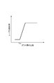
- the present inventors have found that in the glass welded body, the welded state becomes uneven or the glass powder of the glass layer remains as a contaminant. As shown in FIG. 13, when the temperature of the glass layer containing the laser light absorbing material and the glass powder exceeds the melting point Tm, the laser light absorption rate of the glass layer is rapidly increased.
- the laser light absorption rate is low (for example, visible light). It looks whitish below).
- the laser beam is irradiated with the laser power P such that the temperature of the glass layer is higher than the melting point Tm and lower than the crystallization temperature Tc
- the absorption characteristics of the laser light absorbing material remarkably appear due to the collapse of its particle property due to melting of the glass, and the laser light absorption rate of the glass layer increases rapidly (for example, it looks blackish or greenish under visible light). Therefore, when laser light is irradiated with the laser power P, the temperature of the glass layer actually reaches a temperature Ta higher than the crystallization temperature Tc.
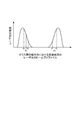
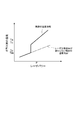
- FIG. 4 when the beam profile of the laser beam has a Gaussian distribution, when the glass layer is irradiated with laser power that melts the glass layer at the periphery of the irradiation region and does not crystallize the glass layer, FIG. As shown in FIG. 4, the temperature reaches the crystallization temperature Tc at the central portion 30a of the glass layer 30 where the intensity of the laser beam is relatively high. As a result, the portion of the central portion 30a of the glass layer 30 opposite to the glass member 40 is crystallized.
- FIG. 15 shows the case where the glass layer 30 is irradiated with laser light from the side opposite to the glass member 40.
- FIG. 16 is a case where a laser beam is irradiated to the glass layer 30 from the opposite side to the glass member 40 similarly to FIG.
- the glass welding method according to the present invention is a glass welding method for manufacturing a glass welded body by welding the first glass member and the second glass member so as to be along the extended planned welding region.
- the glass layer welding method according to the present invention is a glass layer fixing method for producing a glass layer fixing member by fixing the glass layer to the first glass member, and along the extended planned welding region, A step of disposing a glass layer containing a laser light absorbing material and glass powder on the first glass member with a predetermined width, and moving the irradiation region of the first laser light relatively along the planned welding region.
- the laser beam of 1 is irradiated on the glass layer so that each of the bimodal portions of the beam profile of the first laser beam overlaps each of both edges of the glass layer in the width direction of the glass layer.
- the glass layer is melted and the glass layer is fixed to the first glass member, the glass layer is irradiated with the first laser beam having a ring-shaped irradiation region. The Then, the first laser beam is applied to the glass layer such that each of the bimodal portions of the beam profile of the first laser beam overlaps each of both edge portions of the glass layer in the width direction of the glass layer. Thereby, in the central part of the glass layer, the time during which the relatively high intensity portion of the first laser beam is irradiated is shortened, while at both edges of the glass layer, the intensity of the first laser beam is low. The time during which the relatively high part is irradiated becomes longer.
- the amount of heat input by the irradiation of the first laser beam is made uniform at the center and both edges. Therefore, the central part of the glass layer is prevented from being crystallized or the glass powder that has not been melted is prevented from remaining in the vicinity of both edges of the glass layer, and the central part and both edges of the glass layer are appropriately melted. Can be made. Therefore, according to these glass welding methods and glass layer fixing methods, it becomes possible to manufacture a highly reliable glass welded body.
- the first laser beam is applied to the glass layer so that each peak value of the bimodal portion is located outside each of both edges in the width direction of the glass layer. Irradiation is preferred. In this case, even if the irradiation region of the first laser beam is slightly shifted in the width direction with respect to the glass layer, the intensity of the first laser beam is higher at both edges of the glass layer than at the center of the glass layer. Become. Therefore, it is possible to reliably prevent the unmelted glass powder from remaining in the vicinity of both edge portions.
- the first laser beam is irradiated onto the glass layer from the first glass member side through the first glass member.
- the adhesiveness of the glass layer with respect to a 1st glass member can be improved.
- the portion of the glass layer opposite to the first glass member that is, the portion welded to the second glass member in the glass layer
- the second The welding state of the glass layer with respect to the glass member can be made uniform.
- the third laser beam is irradiated to a part of the glass layer disposed on the first glass member before the step of fixing the glass layer to the first glass member.
- the method further includes a step of melting a part of the glass layer and forming a laser light absorption portion on the glass layer, and in the step of fixing the glass layer to the first glass member, the laser light absorption portion is used as the irradiation start position.
- the glass layer is preferably irradiated with the first laser beam by relatively moving the irradiation region of the first laser beam along the planned welding region.
- the laser light absorption rate of the glass layer disposed on the first glass member increases rapidly when the glass layer melts. Therefore, in order to melt the glass layer disposed on the first glass member, even if the irradiation region of the laser beam is simply moved relatively along the planned welding region, the glass starts from the irradiation start position of the laser beam. An unstable region where the glass layer is not melted over the entire width direction appears until the layer reaches a stable region where the layer is melted over the entire width direction. However, if the laser beam is irradiated with a laser power that melts the glass layer in the entire width direction at the irradiation start position of the laser beam, the glass layer may be crystallized due to excessive heat input.
- a part of the glass layer is irradiated with the third laser light to melt a part of the glass layer, and the third laser A laser light absorbing portion having a laser absorption rate higher than that of the portion not irradiated with light is previously formed on the glass layer. Then, with the laser light absorbing portion as an irradiation start position, the irradiation region of the first laser light is relatively moved along the planned welding region to irradiate the glass layer with the first laser light.
- the glass layer extends over the entire width direction immediately from the vicinity of the starting point where the irradiation of the first laser beam is started. It is possible to obtain a melted stable region. Therefore, it is not necessary to irradiate the laser beam with a laser power that crystallizes the glass layer. And since a 1st glass member and a 2nd glass member are welded through such a stable glass layer, a welding state can be equalize
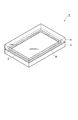
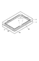
- the glass welded body 1 includes a glass member (first glass member) 4 and a glass member (second glass member) through a glass layer 3 formed along the planned welding region R. ) 5 is welded.
- the glass members 4 and 5 are, for example, rectangular plate-shaped members made of non-alkali glass and having a thickness of 0.7 mm.
- the planned welding region R is rectangular with a predetermined width so as to follow the outer edges of the glass members 4 and 5. It is set in a ring.
- the glass layer 3 is made of, for example, low-melting glass (vanadium phosphate glass, lead borate glass or the like), and is formed in a rectangular ring shape with a predetermined width so as to follow the planned welding region R.
- a glass welding method for manufacturing the glass welded body 1 described above in order to manufacture the glass welded body 1 by welding the glass member 4 and the glass member 5, the glass layer 3 is fixed to the glass member 4.
- a glass layer fixing method for producing a glass layer fixing member in order to manufacture the glass welded body 1 by welding the glass member 4 and the glass member 5, the glass layer 3 is fixed to the glass member 4.
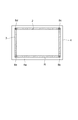
- a paste layer 6 is formed on the surface 4a of the glass member 4 along the planned welding region R by applying a frit paste by a dispenser, screen printing or the like.
- the frit paste is, for example, a powdery glass frit (glass powder) 2 made of low-melting glass (vanadium phosphate glass, lead borate glass, etc.), a laser light absorbing pigment (laser) which is an inorganic pigment such as iron oxide.
- a light absorbing material an organic solvent such as amyl acetate, and a binder that is a resin component (such as acrylic) that is thermally decomposed at a temperature lower than the softening temperature of the glass. That is, the paste layer 6 includes an organic solvent, a binder, a laser light absorbing pigment, and the glass frit 2.
- the glass layer 3 is arrange
- positioned on the surface 4a of the glass member 4 will be in the state where the light scattering exceeding the absorption characteristic of a laser beam absorptive pigment occurs by the particle property of the glass frit 2, etc., and a laser beam absorptivity is low. (For example, the glass layer 3 looks whitish under visible light).
- the glass member 4 is mounted on the mounting table 7 with the glass layer 3 positioned on the upper side in the vertical direction with respect to the glass member 4.
- a laser beam (third laser beam) L ⁇ b> 1 is irradiated with a focused spot on one corner of the glass layer 3 formed in a rectangular ring shape along the planned welding region R.
- the spot diameter of the laser beam L1 is set to be larger than the width of the glass layer 3, and the laser power of the laser beam L1 applied to the glass layer 3 is set to the width direction of the glass layer (approximately the traveling direction of the laser beam L1). (Direction perpendicular to each other) is adjusted so as to be approximately the same. Thereby, a part of the glass layer 3 is melted equally in the entire width direction, and the laser beam absorbing portion 8a having a high laser beam absorption rate is formed over the entire width direction.
- the remaining three corners of the glass layer 3 are similarly irradiated with the laser light L1 in order to form laser light absorbing portions 8b, 8c, and 8d.
- the absorption characteristics of the laser light absorbing pigment appear remarkably due to the particle characteristics of the glass frit 2 being melted, and the laser light absorptance of this portion is determined by the laser light L1. (For example, under visible light, only the corners corresponding to the laser light absorbing portions 8a to 8d appear dark or green).
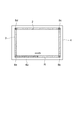
- the laser beam (first laser beam) L ⁇ b> 2 is scheduled to be welded with the laser beam absorbing portion 8 a as the starting point (irradiation start position) and the focused spot on the glass layer 3. Irradiate along the region R. That is, the laser beam L2 is irradiated to the glass layer 3 by relatively moving the irradiation region of the laser beam L2 along the planned welding region R with the laser beam absorbing portion 8a as the irradiation start position. At this time, the laser beam L2 is placed through the opening (not shown) provided in the mounting table 7 and the glass member 4 with the glass layer 3 positioned vertically above the glass member 4.
- the glass layer 3 is irradiated from the glass member 4 side (the same applies to the laser light L1). As a result, the binder is gasified and removed from the glass layer 3, and the glass layer 3 is melted and re-solidified, and the glass layer 3 is baked and fixed on the surface 4a of the glass member 4 (temporary firing). A fixing member is manufactured.
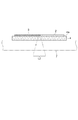
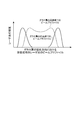
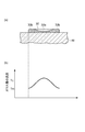
- the irradiation region of the laser beam L2 for pre-baking has a ring shape in the glass layer 3 as shown in FIG.
- the bimodal portion M of the beam profile (intensity distribution) of the laser beam L2 (a convex shape having a relatively high laser beam intensity).
- Each of the portions) overlaps with each of the two edge portions 3b of the glass layer 3, and each peak value Mp of the bimodal portion M is located outside each of the both edge portions 3b.
- the glass layer 3 When the glass layer 3 is temporarily fired, since the irradiation of the laser light L2 is started with the laser light absorption portion 8a having a previously increased laser light absorption rate as the irradiation start position, immediately after the irradiation start position. The glass layer 3 melts over the entire width direction. Thereby, the unstable region where the melting of the glass layer 3 becomes unstable is reduced over the entire region to be welded R, and a stable region where the melting of the glass layer 3 is stable is obtained. Further, since the laser beam absorbing portions 8b to 8d are provided in the remaining three corner portions, the corner portions that are likely to be loaded when functioning as a glass welded body are surely melted during the preliminary firing.
- the glass layer 3 fixed on the surface 4a of the glass member 4 has a remarkable absorption characteristic of the laser-absorbing pigment due to, for example, the loss of its particle property due to melting of the glass frit 2 over the entire region R to be welded. It appears and the laser light absorption rate is high.
- the glass member 5 is overlaid on the glass layer fixing member 10 (that is, the glass member 4 on which the glass layer 3 is fixed) via the glass layer 3.
- the laser beam (second laser beam) L ⁇ b> 3 is irradiated along the planned welding region R with the focused spot on the glass layer 3. That is, the irradiation region of the laser beam L3 is relatively moved along the planned welding region R, and the glass layer 3 is irradiated with the laser beam L3.
- the laser light L3 is absorbed by the glass layer 3 having a high and uniform laser light absorption rate over the entire region to be welded R, and the glass layer 3 and its peripheral portions (the surfaces of the glass members 4 and 5). 4a, 5a portion) is melted and re-solidified (main firing), and the glass member 4 and the glass member 5 are welded along the planned welding region R to obtain the glass welded body 1 (in the welding, the glass layer 3 May melt and the glass members 4 and 5 may not melt).
- the irradiation with the laser beam L3 may be performed on the entire glass layer 3 at once.
- the glass welding method for manufacturing the glass welded body 1
- the glass layer 3 is melted and the glass layer 4 is fixed to the glass member 4 (that is, The glass layer 3 is irradiated with a laser beam L2 having a ring-shaped irradiation region.
- the laser beam L2 is applied to the glass layer 3 so that each of the bimodal portions M of the beam profile of the laser beam L2 overlaps each of both edge portions 3b of the glass layer 3 in the width direction of the glass layer 3. .
- the time during which a portion having a relatively high intensity in the laser light L ⁇ b> 2 is irradiated is shortened, while both edge portions 3 b of the glass layer 3. Then, the time during which the relatively high intensity portion of the laser light L2 is irradiated becomes longer. Therefore, in the glass layer 3, the amount of heat input by the irradiation of the laser beam L2 is made uniform at the central portion 3a and both edge portions 3b, and the temperature of the entire glass layer 3 is higher than the melting point Tm as shown in FIG. And is lower than the crystallization temperature Tc.
- the glass layer 3 is prevented from crystallizing at the center portion 3a of the glass layer 3 during the pre-firing, and the glass frit 2 that has not been melted remains in the vicinity of both edge portions 3b of the glass layer 3. 3 can be melted appropriately. Therefore, according to this glass welding method, it becomes possible to manufacture the glass welded body 1 with high reliability.
- the temporary firing is reliably performed. If this is the case, there will be no situation where the welded state becomes uneven or the glass frit 2 of the glass layer 3 remains as a contaminant.
- the state of temporary baking of the glass layer 3 influences the state of main baking of the glass layer 3, the irradiation condition of the laser light for temporary baking is the irradiation condition of the laser light for main baking. Severe compared to.
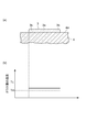
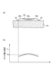
- the laser beam L2 for pre-firing is applied to the glass layer 3 so that each peak value Mp of the bimodal portion M is positioned outside each of the two edge portions 3b of the glass layer 3 in the width direction of the glass layer 3. Irradiated.
- the position P 1 or position P 2 with respect to the position P even if the irradiation region of the laser beam L2 is slightly shifted in the width direction with respect to the glass layer 3.
- the intensity of the laser beam L2 is higher at both edge portions 3b of the glass layer 3 than at the central portion 3a of the glass layer 3. Therefore, it is possible to reliably prevent the glass frit 2 that has not been melted from remaining in the vicinity of both edge portions 3 b of the glass layer 3.
- the laser beam L2 for pre-baking is irradiated to the glass layer 3 through the glass member 4 from the glass member 4 side.
- the adhesiveness of the glass layer 3 with respect to the glass member 4 can be improved.
- the portion of the glass layer 3 opposite to the glass member 4 that is, the portion welded to the glass member 5 in the glass layer 3 is prevented from being crystallized due to excessive heat input, the glass with respect to the glass member 5 is prevented.
- the welding state of the layer 3 can be made uniform.
- a laser beam absorbing portion 8a is formed on the glass layer 3 by irradiating a part of the glass layer 3 with the laser beam L1.
- the laser beam L2 is irradiated to the glass layer 3 by relatively moving the irradiation region of the laser beam L2 along the planned welding region R with the laser beam absorber 8a as the irradiation start position. .
- the glass layer 3 is melted over the entire width direction immediately after starting the irradiation of the laser beam L2. The stable region can be obtained.
- the laser beam L ⁇ b> 2 for temporary firing may be applied to the glass layer 3 from the side opposite to the glass member 4 without passing through the glass member 4.
- the glass layer 3 to be irradiated with the laser beam L2 for pre-baking is not limited to a binder, a laser light absorbing pigment, and a glass frit 2, but an organic solvent, a binder, a laser light absorbing pigment, and It may correspond to the paste layer 6 including the glass frit 2 or may include the laser light absorbing pigment and the glass frit 2 without including the organic solvent and the binder.
- the glass frit 2 is not limited to one having a melting point lower than that of the glass members 4 and 5, and may have a melting point equal to or higher than the melting point of the glass members 4 and 5.
- the laser light absorbing pigment may be contained in the glass frit 2 itself.
- SYMBOLS 1 Glass welded body, 2 ... Glass frit (glass powder), 3 ... Glass layer, 4 ... Glass member (1st glass member), 5 ... Glass member (2nd glass member), 8a-8d ... Laser beam Absorbing section, 10 ... glass layer fixing member, R ... planned welding region, L1 ... laser beam (third laser beam), L2 ... laser beam (first laser beam), L3 ... laser beam (second laser beam) ).
Landscapes
- Engineering & Computer Science (AREA)
- Chemical & Material Sciences (AREA)
- Physics & Mathematics (AREA)
- Optics & Photonics (AREA)
- Plasma & Fusion (AREA)
- Mechanical Engineering (AREA)
- Organic Chemistry (AREA)
- Materials Engineering (AREA)
- Life Sciences & Earth Sciences (AREA)
- Chemical Kinetics & Catalysis (AREA)
- General Chemical & Material Sciences (AREA)
- Geochemistry & Mineralogy (AREA)
- Ceramic Engineering (AREA)
- Manufacturing & Machinery (AREA)
- Joining Of Glass To Other Materials (AREA)
- Manufacture Of Electron Tubes, Discharge Lamp Vessels, Lead-In Wires, And The Like (AREA)
Priority Applications (3)
| Application Number | Priority Date | Filing Date | Title |
|---|---|---|---|
| US13/511,747 US9922790B2 (en) | 2009-11-25 | 2010-09-17 | Glass welding method |
| KR1020127006075A KR101844078B1 (ko) | 2009-11-25 | 2010-09-17 | 유리 용착 방법 및 유리층 정착 방법 |
| CN201080053447.5A CN102666414B (zh) | 2009-11-25 | 2010-09-17 | 玻璃熔接方法及玻璃层固定方法 |
Applications Claiming Priority (2)
| Application Number | Priority Date | Filing Date | Title |
|---|---|---|---|
| JP2009267475A JP5567319B2 (ja) | 2009-11-25 | 2009-11-25 | ガラス溶着方法及びガラス層定着方法 |
| JP2009-267475 | 2009-11-25 |
Publications (1)
| Publication Number | Publication Date |
|---|---|
| WO2011065111A1 true WO2011065111A1 (ja) | 2011-06-03 |
Family
ID=44066214
Family Applications (1)
| Application Number | Title | Priority Date | Filing Date |
|---|---|---|---|
| PCT/JP2010/066144 Ceased WO2011065111A1 (ja) | 2009-11-25 | 2010-09-17 | ガラス溶着方法及びガラス層定着方法 |
Country Status (6)
| Country | Link |
|---|---|
| US (1) | US9922790B2 (enExample) |
| JP (1) | JP5567319B2 (enExample) |
| KR (1) | KR101844078B1 (enExample) |
| CN (1) | CN102666414B (enExample) |
| TW (1) | TWI504468B (enExample) |
| WO (1) | WO2011065111A1 (enExample) |
Cited By (1)
| Publication number | Priority date | Publication date | Assignee | Title |
|---|---|---|---|---|
| TWI674691B (zh) * | 2017-06-20 | 2019-10-11 | 大陸商上海微電子裝備(集團)股份有限公司 | 一種雷射封裝裝置及封裝方法 |
Families Citing this family (22)
| Publication number | Priority date | Publication date | Assignee | Title |
|---|---|---|---|---|
| JP5308718B2 (ja) | 2008-05-26 | 2013-10-09 | 浜松ホトニクス株式会社 | ガラス溶着方法 |
| DE112009001347T5 (de) * | 2008-06-11 | 2011-04-21 | Hamamatsu Photonics K.K., Hamamatsu | Schmelzverbindungsprozess für Glas |
| KR101651300B1 (ko) * | 2008-06-23 | 2016-08-25 | 하마마츠 포토닉스 가부시키가이샤 | 유리 용착 방법 |
| JP5481167B2 (ja) * | 2009-11-12 | 2014-04-23 | 浜松ホトニクス株式会社 | ガラス溶着方法 |
| JP5567319B2 (ja) | 2009-11-25 | 2014-08-06 | 浜松ホトニクス株式会社 | ガラス溶着方法及びガラス層定着方法 |
| JP5525246B2 (ja) * | 2009-11-25 | 2014-06-18 | 浜松ホトニクス株式会社 | ガラス溶着方法及びガラス層定着方法 |
| JP5535589B2 (ja) * | 2009-11-25 | 2014-07-02 | 浜松ホトニクス株式会社 | ガラス溶着方法及びガラス層定着方法 |
| JP5535588B2 (ja) | 2009-11-25 | 2014-07-02 | 浜松ホトニクス株式会社 | ガラス溶着方法及びガラス層定着方法 |
| JP5466929B2 (ja) * | 2009-11-25 | 2014-04-09 | 浜松ホトニクス株式会社 | ガラス溶着方法及びガラス層定着方法 |
| JP5481173B2 (ja) * | 2009-11-25 | 2014-04-23 | 浜松ホトニクス株式会社 | ガラス溶着方法及びガラス層定着方法 |
| JP5481172B2 (ja) | 2009-11-25 | 2014-04-23 | 浜松ホトニクス株式会社 | ガラス溶着方法及びガラス層定着方法 |
| JP5535590B2 (ja) | 2009-11-25 | 2014-07-02 | 浜松ホトニクス株式会社 | ガラス溶着方法及びガラス層定着方法 |
| US20140127857A1 (en) * | 2012-11-07 | 2014-05-08 | Taiwan Semiconductor Manufacturing Company, Ltd. | Carrier Wafers, Methods of Manufacture Thereof, and Packaging Methods |
| US9666763B2 (en) | 2012-11-30 | 2017-05-30 | Corning Incorporated | Glass sealing with transparent materials having transient absorption properties |
| CN105377783B (zh) | 2013-05-10 | 2019-03-08 | 康宁股份有限公司 | 采用低熔融玻璃或薄吸收膜对透明玻璃片进行激光焊接 |
| CN109071325B (zh) * | 2013-05-10 | 2022-04-29 | 康宁股份有限公司 | 包含透明激光焊接区域的密封装置 |
| EP3212589A1 (en) | 2014-10-31 | 2017-09-06 | Corning Incorporated | Laser welded glass packages and methods of making |
| EP3426616A1 (en) * | 2016-03-10 | 2019-01-16 | Corning Incorporated | Sealed devices comprising transparent laser weld regions |
| CN108687442B (zh) * | 2017-03-30 | 2021-10-01 | 法拉第未来公司 | 用于焊接的系统和方法 |
| JP6674422B2 (ja) * | 2017-09-14 | 2020-04-01 | フタバ産業株式会社 | レーザ溶接装置、及び、部材の製造方法 |
| CN110627380A (zh) * | 2019-09-16 | 2019-12-31 | 深圳市裕展精密科技有限公司 | 玻璃复合件、玻璃复合件的制备方法以及激光焊接设备 |
| KR102809214B1 (ko) * | 2020-05-08 | 2025-05-19 | 삼성디스플레이 주식회사 | 표시 장치 및 표시 장치의 제조 방법 |
Citations (4)
| Publication number | Priority date | Publication date | Assignee | Title |
|---|---|---|---|---|
| JP2002366050A (ja) * | 2001-06-12 | 2002-12-20 | Matsushita Electric Ind Co Ltd | 画像表示装置の製造方法、製造装置およびそれを用いて製造した画像表示装置 |
| JP2005213125A (ja) * | 2004-02-02 | 2005-08-11 | Futaba Corp | 電子管と電子管の気密容器の製造方法 |
| JP2006524419A (ja) * | 2003-04-16 | 2006-10-26 | コーニング インコーポレイテッド | フリットにより密封されたガラスパッケージおよびその製造方法 |
| JP2008115057A (ja) * | 2006-11-07 | 2008-05-22 | Electric Power Dev Co Ltd | 封止材料、ガラスパネルの製造方法および色素増感太陽電池 |
Family Cites Families (101)
| Publication number | Priority date | Publication date | Assignee | Title |
|---|---|---|---|---|
| DE1244346B (de) | 1964-10-19 | 1967-07-13 | Menzel Gerhard Glasbearbeitung | Verfahren zum Schneiden von Glas |
| US3663793A (en) | 1971-03-30 | 1972-05-16 | Westinghouse Electric Corp | Method of decorating a glazed article utilizing a beam of corpuscular energy |
| US4343833A (en) | 1979-06-26 | 1982-08-10 | Mitsubishi Denki Kabushiki Kaisha | Method of manufacturing thermal head |
| JPS5915099B2 (ja) * | 1980-03-17 | 1984-04-07 | セントラル硝子株式会社 | 板ガラスの着色部形成方法 |
| JPH02120259A (ja) | 1988-10-28 | 1990-05-08 | Toshiba Corp | ガラスの封止接合体およびその製造方法 |
| JPH05166462A (ja) | 1991-12-17 | 1993-07-02 | Matsushita Electric Ind Co Ltd | 平板型表示装置用真空容器の製造方法 |
| US5489321A (en) | 1994-07-14 | 1996-02-06 | Midwest Research Institute | Welding/sealing glass-enclosed space in a vacuum |
| JP2000313630A (ja) | 1998-08-07 | 2000-11-14 | Shin Meiwa Ind Co Ltd | ガラス融着方法、ガラス融着装置、融着ガラスおよび融着ガラスの製造方法 |
| US6297869B1 (en) | 1998-12-04 | 2001-10-02 | Samsung Electronics Co., Ltd. | Substrate and a liquid crystal display panel capable of being cut by using a laser and a method for manufacturing the same |
| KR100626983B1 (ko) | 1999-06-18 | 2006-09-22 | 미쓰보시 다이야몬도 고교 가부시키가이샤 | 레이저를 이용한 스크라이브 방법 |
| KR100316781B1 (ko) | 2000-02-25 | 2001-12-20 | 김순택 | 레이저를 이용한 유리평판표시패널의 프릿 프레임 밀봉 방법 |
| JP2001326290A (ja) | 2000-03-10 | 2001-11-22 | Seiko Epson Corp | パッケージの封止方法、電子素子モジュールの製造方法、封止装置並びにパッケージ品 |
| JP2002015108A (ja) | 2000-06-30 | 2002-01-18 | Nomura Holding Inc | 企業価値分析装置及び企業価値分析方法 |
| WO2002054436A1 (en) | 2000-12-28 | 2002-07-11 | Jae-Hong Park | A method for sealing a flat panel display in a vacuum |
| JP2002224871A (ja) | 2001-01-31 | 2002-08-13 | Seiko Epson Corp | レーザ切断方法、電気光学装置の製造方法、電気光学装置、電子機器およびレーザ切断装置 |
| JP2002287107A (ja) | 2001-03-28 | 2002-10-03 | Hitachi Ltd | 液晶表示装置およびその製造方法 |
| JP2002367514A (ja) | 2001-06-12 | 2002-12-20 | Matsushita Electric Ind Co Ltd | 表示パネルおよびその製造方法およびその製造装置 |
| US6565400B1 (en) | 2001-06-26 | 2003-05-20 | Candescent Technologies Corporation | Frit protection in sealing process for flat panel displays |
| TW517356B (en) | 2001-10-09 | 2003-01-11 | Delta Optoelectronics Inc | Package structure of display device and its packaging method |
| JP2004182567A (ja) | 2002-12-05 | 2004-07-02 | Nippon Sheet Glass Co Ltd | 真空ガラスパネルの製造方法、及び該製造方法により製造された真空ガラスパネル |
| US20050116245A1 (en) | 2003-04-16 | 2005-06-02 | Aitken Bruce G. | Hermetically sealed glass package and method of fabrication |
| US20040206953A1 (en) | 2003-04-16 | 2004-10-21 | Robert Morena | Hermetically sealed glass package and method of fabrication |
| JP4202836B2 (ja) | 2003-06-17 | 2008-12-24 | 浜松ホトニクス株式会社 | レーザ溶接方法およびレーザ溶接装置 |
| WO2005017580A1 (en) | 2003-07-16 | 2005-02-24 | 3M Innovative Properties Company | Laminates and methods of making same |
| US20050103755A1 (en) | 2003-11-13 | 2005-05-19 | Baker Martin C. | Hand-held laser welding wand reflection shield |
| US20060021977A1 (en) | 2004-07-30 | 2006-02-02 | Menegus Harry E | Process and apparatus for scoring a brittle material incorporating moving optical assembly |
| US7820941B2 (en) | 2004-07-30 | 2010-10-26 | Corning Incorporated | Process and apparatus for scoring a brittle material |
| US7371143B2 (en) | 2004-10-20 | 2008-05-13 | Corning Incorporated | Optimization of parameters for sealing organic emitting light diode (OLED) displays |
| JP4692918B2 (ja) | 2004-12-01 | 2011-06-01 | 日本電気硝子株式会社 | 封着材料 |
| EP1883855B1 (en) | 2005-05-16 | 2011-07-20 | Donnelly Corporation | Vehicle mirror assembly with indicia at reflective element |
| US20070001579A1 (en) | 2005-06-30 | 2007-01-04 | Eun-Suk Jeon | Glass-to-glass joining method using laser, vacuum envelope manufactured by the method, electron emission display having the vacuum envelope |
| CN101242951B (zh) | 2005-08-09 | 2012-10-31 | 旭硝子株式会社 | 薄板玻璃层压体以及利用薄板玻璃层压体的显示装置的制造方法 |
| JP2007090405A (ja) | 2005-09-29 | 2007-04-12 | Epson Toyocom Corp | 積層光学素子、及びその製造方法 |
| US7537504B2 (en) | 2005-12-06 | 2009-05-26 | Corning Incorporated | Method of encapsulating a display element with frit wall and laser beam |
| EP1958248B1 (en) * | 2005-12-06 | 2016-03-09 | Corning Incorporated | System and method for frit sealing glass packages |
| US7641976B2 (en) | 2005-12-06 | 2010-01-05 | Corning Incorporated | Glass package that is hermetically sealed with a frit and method of fabrication |
| DE602006021468D1 (de) | 2005-12-06 | 2011-06-01 | Corning Inc | Herstellungsverfahren für eine luftdicht versiegelte Glasverpackung |
| KR100673765B1 (ko) | 2006-01-20 | 2007-01-24 | 삼성에스디아이 주식회사 | 유기전계발광 표시장치 및 그 제조방법 |
| JP4456092B2 (ja) | 2006-01-24 | 2010-04-28 | 三星モバイルディスプレイ株式會社 | 有機電界発光表示装置及びその製造方法 |
| KR100671647B1 (ko) | 2006-01-26 | 2007-01-19 | 삼성에스디아이 주식회사 | 유기전계발광 표시 장치 |
| KR100732808B1 (ko) | 2006-01-26 | 2007-06-27 | 삼성에스디아이 주식회사 | 유기전계발광 표시장치의 제조방법 |
| KR100713987B1 (ko) | 2006-02-20 | 2007-05-04 | 삼성에스디아이 주식회사 | 기판 밀착장치 및 이를 이용한 유기전계발광 표시장치의밀봉방법 |
| JP4977391B2 (ja) | 2006-03-27 | 2012-07-18 | 日本電気株式会社 | レーザ切断方法、表示装置の製造方法、および表示装置 |
| CN101437772B (zh) | 2006-05-08 | 2011-09-07 | 旭硝子株式会社 | 薄板玻璃叠层体、使用了薄板玻璃叠层体的显示装置的制造方法及支持用玻璃基板 |
| KR101274807B1 (ko) | 2006-06-30 | 2013-06-13 | 엘지디스플레이 주식회사 | 유기 전계 발광 표시 장치 및 이의 제조 방법 |
| US20080124558A1 (en) | 2006-08-18 | 2008-05-29 | Heather Debra Boek | Boro-silicate glass frits for hermetic sealing of light emitting device displays |
| US7800303B2 (en) | 2006-11-07 | 2010-09-21 | Corning Incorporated | Seal for light emitting display device, method, and apparatus |
| JP2008115067A (ja) | 2006-11-07 | 2008-05-22 | Lemi Ltd | フラットパネルディスプレィ薄板の割断方法 |
| JP2008127223A (ja) | 2006-11-17 | 2008-06-05 | Lemi Ltd | フラットパネルディスプレィ薄板の割断方法 |
| DE102007008634B3 (de) | 2007-02-16 | 2008-08-07 | Jenoptik Automatisierungstechnik Gmbh | Verfahren und Vorrichtung zum Trennen von Verbundglasscheiben |
| US20080254268A1 (en) * | 2007-04-03 | 2008-10-16 | Asahi Glass Company Limited | Color toner for electro printing, and process for producing glass plate provided with ceramic color print, employing it |
| DE112008000027B4 (de) | 2007-05-30 | 2015-05-21 | Panasonic Intellectual Property Management Co., Ltd. | Laminier-Formgebungsvorrichtung |
| JP2009070687A (ja) | 2007-09-13 | 2009-04-02 | Canon Inc | 気密容器の製造方法 |
| US8247730B2 (en) * | 2007-09-28 | 2012-08-21 | Corning Incorporated | Method and apparatus for frit sealing with a variable laser beam |
| JP2009123421A (ja) | 2007-11-13 | 2009-06-04 | Canon Inc | 気密容器の製造方法 |
| US7815480B2 (en) | 2007-11-30 | 2010-10-19 | Corning Incorporated | Methods and apparatus for packaging electronic components |
| JP4928483B2 (ja) | 2008-02-22 | 2012-05-09 | 浜松ホトニクス株式会社 | ガラス溶着方法 |
| JP4980265B2 (ja) | 2008-02-22 | 2012-07-18 | 浜松ホトニクス株式会社 | ガラス溶着方法 |
| DE112009000987T5 (de) | 2008-04-25 | 2011-03-24 | Hamamatsu Photonics K.K., Hamamatsu | Verfahren zum Schmelzen von Glas |
| TWI421601B (zh) | 2008-04-25 | 2014-01-01 | Au Optronics Corp | 適用雷射切割技術之顯示面板及其母板 |
| JP5308718B2 (ja) | 2008-05-26 | 2013-10-09 | 浜松ホトニクス株式会社 | ガラス溶着方法 |
| JP5308717B2 (ja) | 2008-05-26 | 2013-10-09 | 浜松ホトニクス株式会社 | ガラス溶着方法 |
| US8147632B2 (en) * | 2008-05-30 | 2012-04-03 | Corning Incorporated | Controlled atmosphere when sintering a frit to a glass plate |
| US7992411B2 (en) | 2008-05-30 | 2011-08-09 | Corning Incorporated | Method for sintering a frit to a glass plate |
| US8448468B2 (en) | 2008-06-11 | 2013-05-28 | Corning Incorporated | Mask and method for sealing a glass envelope |
| CN102066277B (zh) | 2008-06-11 | 2013-09-11 | 浜松光子学株式会社 | 玻璃熔接方法 |
| DE112009001347T5 (de) | 2008-06-11 | 2011-04-21 | Hamamatsu Photonics K.K., Hamamatsu | Schmelzverbindungsprozess für Glas |
| WO2009157281A1 (ja) | 2008-06-23 | 2009-12-30 | 浜松ホトニクス株式会社 | ガラス溶着方法 |
| KR101651300B1 (ko) | 2008-06-23 | 2016-08-25 | 하마마츠 포토닉스 가부시키가이샤 | 유리 용착 방법 |
| EP2300381A4 (en) | 2008-07-16 | 2016-04-27 | Ferro Corp | GLASS COMPOSITIONS WITH MELT ADHESIVE SEALS AND MANUFACTURING AND USE METHOD THEREFOR |
| EP2321694A4 (en) | 2008-07-28 | 2012-05-30 | Corning Inc | METHOD FOR SEALING A LIQUID IN A GLASS PACKAGING AND RESULTING GLASS PACKAGING |
| US20100095705A1 (en) | 2008-10-20 | 2010-04-22 | Burkhalter Robert S | Method for forming a dry glass-based frit |
| US20100116119A1 (en) | 2008-11-10 | 2010-05-13 | Bayne John F | Method for separating a composite glass assembly |
| US8245536B2 (en) | 2008-11-24 | 2012-08-21 | Corning Incorporated | Laser assisted frit sealing of high CTE glasses and the resulting sealed glass package |
| EP2351717A4 (en) | 2008-11-26 | 2012-04-25 | Asahi Glass Co Ltd | GLASS ELEMENT WITH A LAYER OF A SEALING / BONDING MATERIAL, ELECTRONIC DEVICE AND METHOD OF MANUFACTURING THEREOF |
| KR20110098894A (ko) | 2008-12-12 | 2011-09-02 | 아사히 가라스 가부시키가이샤 | 봉착 유리, 봉착 재료층 부착 유리 부재, 및 전자 디바이스와 그 제조 방법 |
| KR20100099619A (ko) | 2009-03-03 | 2010-09-13 | 삼성모바일디스플레이주식회사 | 유기 전계 발광 표시장치의 제조방법 |
| KR101097307B1 (ko) | 2009-04-16 | 2011-12-21 | 삼성모바일디스플레이주식회사 | 실링 장치 |
| US8440479B2 (en) | 2009-05-28 | 2013-05-14 | Corning Incorporated | Method for forming an organic light emitting diode device |
| SG176881A1 (en) | 2009-06-30 | 2012-02-28 | Asahi Glass Co Ltd | Glass member with sealing material layer, electronic device using same, and method for manufacturing the electronic device |
| WO2011010489A1 (ja) | 2009-07-23 | 2011-01-27 | 旭硝子株式会社 | 封着材料層付きガラス部材の製造方法及び製造装置、並びに電子デバイスの製造方法 |
| JP5481167B2 (ja) | 2009-11-12 | 2014-04-23 | 浜松ホトニクス株式会社 | ガラス溶着方法 |
| JP5481173B2 (ja) | 2009-11-25 | 2014-04-23 | 浜松ホトニクス株式会社 | ガラス溶着方法及びガラス層定着方法 |
| JP5481172B2 (ja) | 2009-11-25 | 2014-04-23 | 浜松ホトニクス株式会社 | ガラス溶着方法及びガラス層定着方法 |
| JP5535590B2 (ja) | 2009-11-25 | 2014-07-02 | 浜松ホトニクス株式会社 | ガラス溶着方法及びガラス層定着方法 |
| JP5535588B2 (ja) | 2009-11-25 | 2014-07-02 | 浜松ホトニクス株式会社 | ガラス溶着方法及びガラス層定着方法 |
| JP5466929B2 (ja) | 2009-11-25 | 2014-04-09 | 浜松ホトニクス株式会社 | ガラス溶着方法及びガラス層定着方法 |
| JP5535589B2 (ja) | 2009-11-25 | 2014-07-02 | 浜松ホトニクス株式会社 | ガラス溶着方法及びガラス層定着方法 |
| JP5567319B2 (ja) | 2009-11-25 | 2014-08-06 | 浜松ホトニクス株式会社 | ガラス溶着方法及びガラス層定着方法 |
| JP5525246B2 (ja) | 2009-11-25 | 2014-06-18 | 浜松ホトニクス株式会社 | ガラス溶着方法及びガラス層定着方法 |
| KR101113381B1 (ko) | 2009-11-30 | 2012-03-02 | 삼성에스디아이 주식회사 | 배터리 팩 |
| TWI497466B (zh) | 2010-03-19 | 2015-08-21 | Asahi Glass Co Ltd | Electronic device and manufacturing method thereof |
| WO2011130632A1 (en) | 2010-04-15 | 2011-10-20 | Ferro Corporation | Low-melting lead-free bismuth sealing glasses |
| CN102870230B (zh) | 2010-04-27 | 2016-04-20 | 费罗公司 | 用于气密密封导电馈通的方法 |
| JP2011233479A (ja) | 2010-04-30 | 2011-11-17 | Canon Inc | 気密容器および画像表示装置の製造方法 |
| WO2011158805A1 (ja) | 2010-06-14 | 2011-12-22 | 旭硝子株式会社 | 封着材料ペーストとそれを用いた電子デバイスの製造方法 |
| WO2012011268A1 (ja) | 2010-07-23 | 2012-01-26 | パナソニック株式会社 | 表示パネル及びその製造方法 |
| JP5947098B2 (ja) | 2011-05-13 | 2016-07-06 | 株式会社半導体エネルギー研究所 | ガラス封止体の作製方法および発光装置の作製方法 |
| JP6111022B2 (ja) | 2011-06-17 | 2017-04-05 | 株式会社半導体エネルギー研究所 | 封止体の作製方法および発光装置の作製方法 |
| KR102058387B1 (ko) | 2011-11-28 | 2019-12-24 | 가부시키가이샤 한도오따이 에네루기 켄큐쇼 | 유리 패턴 및 그 형성 방법, 밀봉체 및 그 제작 방법, 및 발광 장치 |
| KR20130118491A (ko) | 2012-04-20 | 2013-10-30 | 삼성디스플레이 주식회사 | 레이저 실링 장치 및 이를 이용한 유기 발광 표시 장치의 제조 방법 |
-
2009
- 2009-11-25 JP JP2009267475A patent/JP5567319B2/ja active Active
-
2010
- 2010-09-17 TW TW099131761A patent/TWI504468B/zh not_active IP Right Cessation
- 2010-09-17 CN CN201080053447.5A patent/CN102666414B/zh not_active Expired - Fee Related
- 2010-09-17 KR KR1020127006075A patent/KR101844078B1/ko not_active Expired - Fee Related
- 2010-09-17 US US13/511,747 patent/US9922790B2/en not_active Expired - Fee Related
- 2010-09-17 WO PCT/JP2010/066144 patent/WO2011065111A1/ja not_active Ceased
Patent Citations (4)
| Publication number | Priority date | Publication date | Assignee | Title |
|---|---|---|---|---|
| JP2002366050A (ja) * | 2001-06-12 | 2002-12-20 | Matsushita Electric Ind Co Ltd | 画像表示装置の製造方法、製造装置およびそれを用いて製造した画像表示装置 |
| JP2006524419A (ja) * | 2003-04-16 | 2006-10-26 | コーニング インコーポレイテッド | フリットにより密封されたガラスパッケージおよびその製造方法 |
| JP2005213125A (ja) * | 2004-02-02 | 2005-08-11 | Futaba Corp | 電子管と電子管の気密容器の製造方法 |
| JP2008115057A (ja) * | 2006-11-07 | 2008-05-22 | Electric Power Dev Co Ltd | 封止材料、ガラスパネルの製造方法および色素増感太陽電池 |
Cited By (1)
| Publication number | Priority date | Publication date | Assignee | Title |
|---|---|---|---|---|
| TWI674691B (zh) * | 2017-06-20 | 2019-10-11 | 大陸商上海微電子裝備(集團)股份有限公司 | 一種雷射封裝裝置及封裝方法 |
Also Published As
| Publication number | Publication date |
|---|---|
| JP5567319B2 (ja) | 2014-08-06 |
| KR101844078B1 (ko) | 2018-03-30 |
| US20120240632A1 (en) | 2012-09-27 |
| US9922790B2 (en) | 2018-03-20 |
| KR20120104967A (ko) | 2012-09-24 |
| CN102666414B (zh) | 2014-11-26 |
| TW201119778A (en) | 2011-06-16 |
| TWI504468B (zh) | 2015-10-21 |
| JP2011111339A (ja) | 2011-06-09 |
| CN102666414A (zh) | 2012-09-12 |
Similar Documents
| Publication | Publication Date | Title |
|---|---|---|
| JP5567319B2 (ja) | ガラス溶着方法及びガラス層定着方法 | |
| JP5481172B2 (ja) | ガラス溶着方法及びガラス層定着方法 | |
| JP5535653B2 (ja) | ガラス溶着方法 | |
| JP5535588B2 (ja) | ガラス溶着方法及びガラス層定着方法 | |
| JP5535594B2 (ja) | ガラス層定着方法 | |
| JP5535589B2 (ja) | ガラス溶着方法及びガラス層定着方法 | |
| JP5481173B2 (ja) | ガラス溶着方法及びガラス層定着方法 | |
| JP5140201B2 (ja) | ガラス層定着方法 | |
| WO2011065104A1 (ja) | ガラス溶着方法 | |
| JP5651327B2 (ja) | ガラス溶着方法 |
Legal Events
| Date | Code | Title | Description |
|---|---|---|---|
| WWE | Wipo information: entry into national phase |
Ref document number: 201080053447.5 Country of ref document: CN |
|
| 121 | Ep: the epo has been informed by wipo that ep was designated in this application |
Ref document number: 10832958 Country of ref document: EP Kind code of ref document: A1 |
|
| ENP | Entry into the national phase |
Ref document number: 20127006075 Country of ref document: KR Kind code of ref document: A |
|
| NENP | Non-entry into the national phase |
Ref country code: DE |
|
| WWE | Wipo information: entry into national phase |
Ref document number: 13511747 Country of ref document: US |
|
| 122 | Ep: pct application non-entry in european phase |
Ref document number: 10832958 Country of ref document: EP Kind code of ref document: A1 |