WO2011055676A1 - 空気調和装置の室内機 - Google Patents
空気調和装置の室内機 Download PDFInfo
- Publication number
- WO2011055676A1 WO2011055676A1 PCT/JP2010/069164 JP2010069164W WO2011055676A1 WO 2011055676 A1 WO2011055676 A1 WO 2011055676A1 JP 2010069164 W JP2010069164 W JP 2010069164W WO 2011055676 A1 WO2011055676 A1 WO 2011055676A1
- Authority
- WO
- WIPO (PCT)
- Prior art keywords
- air
- outlet
- indoor unit
- wind direction
- air outlet
- Prior art date
Links
Images


Classifications
-
- F—MECHANICAL ENGINEERING; LIGHTING; HEATING; WEAPONS; BLASTING
- F24—HEATING; RANGES; VENTILATING
- F24F—AIR-CONDITIONING; AIR-HUMIDIFICATION; VENTILATION; USE OF AIR CURRENTS FOR SCREENING
- F24F1/00—Room units for air-conditioning, e.g. separate or self-contained units or units receiving primary air from a central station
- F24F1/0007—Indoor units, e.g. fan coil units
- F24F1/0011—Indoor units, e.g. fan coil units characterised by air outlets
- F24F1/0014—Indoor units, e.g. fan coil units characterised by air outlets having two or more outlet openings
-
- F—MECHANICAL ENGINEERING; LIGHTING; HEATING; WEAPONS; BLASTING
- F24—HEATING; RANGES; VENTILATING
- F24F—AIR-CONDITIONING; AIR-HUMIDIFICATION; VENTILATION; USE OF AIR CURRENTS FOR SCREENING
- F24F1/00—Room units for air-conditioning, e.g. separate or self-contained units or units receiving primary air from a central station
- F24F1/0007—Indoor units, e.g. fan coil units
- F24F1/0043—Indoor units, e.g. fan coil units characterised by mounting arrangements
- F24F1/0047—Indoor units, e.g. fan coil units characterised by mounting arrangements mounted in the ceiling or at the ceiling
-
- F—MECHANICAL ENGINEERING; LIGHTING; HEATING; WEAPONS; BLASTING
- F24—HEATING; RANGES; VENTILATING
- F24F—AIR-CONDITIONING; AIR-HUMIDIFICATION; VENTILATION; USE OF AIR CURRENTS FOR SCREENING
- F24F13/00—Details common to, or for air-conditioning, air-humidification, ventilation or use of air currents for screening
- F24F13/08—Air-flow control members, e.g. louvres, grilles, flaps or guide plates
- F24F13/10—Air-flow control members, e.g. louvres, grilles, flaps or guide plates movable, e.g. dampers
- F24F13/14—Air-flow control members, e.g. louvres, grilles, flaps or guide plates movable, e.g. dampers built up of tilting members, e.g. louvre
-
- F—MECHANICAL ENGINEERING; LIGHTING; HEATING; WEAPONS; BLASTING
- F24—HEATING; RANGES; VENTILATING
- F24F—AIR-CONDITIONING; AIR-HUMIDIFICATION; VENTILATION; USE OF AIR CURRENTS FOR SCREENING
- F24F13/00—Details common to, or for air-conditioning, air-humidification, ventilation or use of air currents for screening
- F24F13/20—Casings or covers
-
- F—MECHANICAL ENGINEERING; LIGHTING; HEATING; WEAPONS; BLASTING
- F24—HEATING; RANGES; VENTILATING
- F24F—AIR-CONDITIONING; AIR-HUMIDIFICATION; VENTILATION; USE OF AIR CURRENTS FOR SCREENING
- F24F13/00—Details common to, or for air-conditioning, air-humidification, ventilation or use of air currents for screening
- F24F13/02—Ducting arrangements
- F24F13/06—Outlets for directing or distributing air into rooms or spaces, e.g. ceiling air diffuser
- F24F2013/0616—Outlets that have intake openings
Definitions
- the present invention relates to an indoor unit of an air conditioner.
- Patent Document 1 Japanese Patent Laid-Open No. 2002-349892
- Patent Document 1 Japanese Patent Laid-Open No. 2002-349892
- a wide range of the target space can be harmonized by the conditioned air blown from each outlet.
- Patent Document 1 Japanese Patent Laid-Open No. 2002-349892
- the shape of the air outlet is formed so that the length in the longitudinal direction is considerably longer than the length in the width direction. Rectangle. For this reason, it is difficult to make the conditioned air blown out from the blowout port reach farther.
- it is also conceivable to improve the far reachability of the conditioned air by relatively increasing the length in the width direction with respect to the length in the longitudinal direction with respect to the shape of the air outlet.
- the length in the width direction is increased, the size of the lower surface of the indoor unit is increased.
- This invention is made
- the subject of this invention increases the reach
- An object of the present invention is to provide an indoor unit of an air conditioner that can be used.
- the indoor unit of the air conditioner of the first invention includes an indoor unit casing and a wind direction adjusting member.
- the indoor unit casing has a suction port and a blowout port whose edge on the suction port side swells toward the suction port side.
- the wind direction adjusting member covers at least a part of the air outlet, and the edge on the inlet side swells toward the inlet side.
- the indoor unit of this air conditioner has an air outlet that is formed to swell toward the suction port, so that the air flow bundle is thickened and the initial velocity of the conditioned air passing through the vicinity of the center of the air outlet is easily maintained. The reach of conditioned air can be increased.
- the direction which the blower outlet swells is the suction inlet side, the enlargement of the lower surface of an indoor unit can be suppressed. Furthermore, although the distance between the air outlet and the air inlet becomes closer by inflating the air outlet toward the air inlet side in this way, the shape of the airflow direction adjusting member on the air inlet side is the same as that of the air outlet. Therefore, it is easy to block the air flow from the portion on the suction port side of the air outlet toward the suction port, and a short circuit can be suppressed. Thereby, it becomes possible to increase the reach distance of the conditioned air blown out from the air outlet while suppressing the enlargement of the lower surface of the indoor unit and the short circuit.
- An indoor unit of an air conditioner according to a second aspect of the present invention is the indoor unit of the air conditioner of the first aspect, which is a ceiling embedded type. And it has the structure which orient
- Directing the direction of air flow blown from the vicinity of the longitudinal end of the blower outlet downward from the direction of air flow blown from the center in the longitudinal direction of the blower outlet is a blowout outlet alone, a wind direction adjusting member alone, or The air outlet and the wind direction adjusting member can be cooperated.
- the air flow is slower in the vicinity of the longitudinal end of the air outlet than in the vicinity of the center in the longitudinal direction, and the air tends to flow along the ceiling surface.
- the indoor unit of this air conditioner the conditioned air blown from the vicinity of the longitudinal end of the air outlet can be guided in a direction away from the ceiling surface rather than the conditioned air blown from the center. is made of. Thereby, ceiling dirt can be suppressed.
- the indoor unit of the air conditioner of the third invention is the indoor unit of the air conditioner of the second invention, wherein the air outlet has an inclination of the edge surface in the vicinity of the end in the longitudinal direction, and an inclination of the center edge surface in the longitudinal direction. It is formed to be tighter.
- the indoor unit of this air conditioner can guide the air flow direction blown from the vicinity of the longitudinal end of the air outlet in the direction away from the ceiling surface, regardless of the direction of the wind direction adjusting member. Therefore, the effect of preventing ceiling dirt can be obtained more reliably.
- the indoor unit of the air conditioner of the fourth invention is the indoor unit of the air conditioner of either the second invention or the third invention, wherein the bulge of the air outlet is near the end in the longitudinal direction and becomes wider toward the end. It is formed by shortening the length in the direction.
- the bulge of the wind direction adjusting member is formed by shortening the length in the width direction toward the end in the vicinity of the end in the longitudinal direction. Since the indoor unit of this air conditioner is formed so that the length in the width direction becomes shorter toward the longitudinal direction end of the air outlet, the air flow bundle passing through the center of the air outlet is thicker, and the initial velocity is further increased. It can be made easy to maintain, and the reach distance of the conditioned air blown out from the air outlet can be increased more effectively.
- the indoor unit of the air conditioner of the fifth invention is the indoor unit of the air conditioner of the fourth invention, wherein the length in the width direction at the end in the longitudinal direction of the outlet is the length in the width direction at the center in the longitudinal direction. Of 40 to 80%.
- the blower outlet has a linear shape part which connects the bulging parts of the longitudinal direction edge part vicinity.
- the length in the width direction at the end in the longitudinal direction of the wind direction adjusting member is 20 to 60% of the length in the width direction at the center in the longitudinal direction.
- the wind direction adjusting member has a linear portion that connects the bulging portions near the ends in the longitudinal direction.
- the air outlet has a linear portion having a width wider than that of the end portion, so that the reach distance of the conditioned air can be increased. And since it has the same shape also about a wind direction adjustment member, the wind direction adjustment function of the conditioned air which passes through such a blower outlet is securable. This makes it possible to increase the reach of conditioned air while ensuring the wind direction adjusting function.
- the indoor unit of the air conditioner according to a sixth aspect of the present invention is the indoor unit of the air conditioner according to the fourth or fifth aspect of the present invention, wherein the degree of swelling of the air outlet toward the inlet port is at least that of the air outlet side of the air outlet. Is greater than the degree of swelling to the opposite side.
- the degree of swelling of the wind direction adjusting member toward the suction port side is at least larger than the degree of swelling of the wind direction adjusting member toward the side opposite to the suction port side.
- the blowout outlet becomes closer to the end in the longitudinal direction, the blowing wind speed becomes lower and a short circuit is likely to occur, but the distance from the suction port becomes longer toward the end in the longitudinal direction.
- the air direction adjusting member increases the degree of swelling on the suction port side, similarly to the shape of the air outlet, without forming a shape that cuts out the suction port side in the vicinity of the end in the longitudinal direction. For this reason, the short circuit which the air which leaks from between the suction inlet side part in the longitudinal direction edge part vicinity of the wind direction adjustment member and the suction port side part in the longitudinal direction edge part of a blower outlet can be suppressed.
- An indoor unit of an air conditioner according to a seventh aspect of the present invention is the indoor unit of the air conditioner according to any of the second to sixth aspects of the invention, wherein the air outlet has a shape portion that is recessed toward the inside of the air outlet. Absent. The edge of the wind direction adjusting member does not have a shape portion that is recessed toward the inside of the wind direction adjusting member. Since the indoor unit of this air conditioner does not have a shape part recessed inward, it becomes possible to prevent ceiling dirt more effectively.
- An indoor unit of an air conditioner according to an eighth aspect of the present invention is the indoor unit of the air conditioner according to any of the first to seventh aspects of the invention, wherein the air inlet side of the airflow direction adjusting member is along the inlet side of the air outlet. Is formed.
- the indoor unit of this air conditioner can more effectively prevent a short circuit flowing toward the inlet side from the inlet side end of the outlet, and the shape relationship between the outlet and the wind direction adjusting member Designability can also be improved.
- An indoor unit of an air conditioner according to a ninth aspect of the present invention is the indoor unit of the air conditioner according to any one of the first to eighth aspects of the invention, wherein the air outlet provided with the wind direction adjusting member is at least 4 so as to surround the inlet. One is provided. Since the indoor unit of this air conditioning apparatus can blow out conditioned air in four directions, a wide target space that can be harmonized can be secured.
- An indoor unit for an air conditioner according to a tenth aspect of the present invention is the indoor unit for an air conditioner according to the ninth aspect, further comprising a continuous air outlet.
- the continuous air outlet is further provided between the air outlets in addition to the air outlet provided with the wind direction adjusting member.
- the indoor unit of the air conditioner can further provide conditioned air evenly around the indoor unit by further including a continuous air outlet. And if the total area where the conditioned air is blown out becomes large by providing the continuous air outlet in this way, there is a risk that it is difficult to maintain the initial speed of the conditioned air passing through the air outlet provided with the wind direction adjusting member. Even in such a case, by adopting a shape that swells inward with respect to the shape of the air outlet, it is possible to suppress the degree of decrease in the initial velocity of the conditioned air from the air outlet to a small level.
- An indoor unit for an air conditioner according to an eleventh aspect of the invention is the indoor unit for an air conditioner according to any of the first to tenth aspects, further comprising a wind direction adjustment control unit.
- a wind direction adjustment control part adjusts the direction of the wind blown from a blower outlet by adjusting the attitude
- a wind direction adjustment control part adjusts the attitude
- the indoor unit of this air conditioner when the air conditioning operation is stopped, the interior of the air outlet is concealed by the wind direction adjusting member, so that the contents of the indoor unit are difficult to see and the design can be improved.
- the indoor unit of the air conditioner according to the first aspect of the present invention it is possible to increase the reach of conditioned air blown out from the air outlet while suppressing the increase in size of the lower surface of the indoor unit and the short circuit.
- ceiling contamination can be suppressed.
- the effect of preventing ceiling dirt can be obtained more reliably.
- the airflow bundle of the airflow blown from the center of the outlet can be thickened, the initial speed can be easily maintained, and the reach distance of the conditioned air can be increased. It becomes possible.
- the indoor unit of the air conditioner according to the seventh aspect of the invention it is possible to more effectively prevent ceiling dirt.
- the indoor unit for an air conditioner according to the eighth aspect of the invention it is possible to suppress short circuits while improving design.
- a wide space that can be harmonized can be secured.
- conditioned air can be supplied evenly to the surroundings while suppressing a decrease in the reach of conditioned air.
- the interior of the air outlet is concealed by the wind direction adjusting member, so that the contents of the indoor unit are difficult to see and the design can be improved.
- FIG. 4 is a schematic cross-sectional view taken along the line AOA in FIG. 3 in the indoor unit of the air conditioner.
- FIG. 12 is a schematic cross-sectional view showing an example of a posture state of the wind direction adjusting unit in the vicinity of the first long-side outlet on the BB cut surface in FIG. 11 and during independent wind direction control or interlocking wind direction control.
- FIG. 12 is a schematic cross-sectional view showing an example of a posture state of the wind direction adjusting unit in the vicinity of the first long-side outlet on the CC cut surface in FIG. 11 and during independent wind direction control or interlocking wind direction control. It is an image figure of air volume suppression control.
- FIG. 12 is a schematic cross-sectional view showing an example of a posture state of the wind direction adjusting unit in the vicinity of the first long-side outlet on the CC cut surface in FIG. 11 and during independent wind direction control or interlocking wind direction control.
- FIG. 12 is a schematic cross-sectional view showing an example of a posture state of the wind direction adjusting unit in the vicinity of the first long-side outlet at the BB cut surface in FIG. It is an external appearance perspective view of the indoor unit of the conventional air conditioning apparatus. It is a bottom view external appearance block diagram of the indoor unit of the conventional air conditioning apparatus.
- FIG. 1 is a schematic configuration diagram of an air conditioner 1 in which an indoor unit according to an embodiment of the present invention is employed.
- the air conditioner 1 is a type that is installed by embedding the indoor unit type in the ceiling, and has eight air outlets, of which the air angle adjustment of the air direction adjusting plate provided at the four air outlets is adjusted. The rotation can be controlled independently for each plate.
- This air conditioner 1 is a split type air conditioner, and mainly includes an outdoor unit 2, an indoor unit 4, a liquid refrigerant communication tube 5 and a gas refrigerant communication tube 6 that connect the outdoor unit 2 and the indoor unit 4, and The control unit 7 is included, and a vapor compression refrigerant circuit 10 is configured.
- Outdoor unit 2 The outdoor unit 2 is installed outside the room, and mainly includes a compressor 21, a four-way switching valve 22, an outdoor heat exchanger 23, an expansion valve 24, a liquid side closing valve 25, a gas side closing valve 26, and an outdoor unit.
- a fan 27 is provided.
- the compressor 21 is a compressor for sucking low-pressure gas refrigerant and compressing it into a high-pressure gas refrigerant and discharging it.
- the four-way switching valve 22 is a valve for switching the direction of refrigerant flow when switching between cooling and heating.
- the four-way switching valve 22 can connect the discharge side of the compressor 21 and the gas side of the outdoor heat exchanger 23 and can connect the gas side closing valve 26 and the suction side of the compressor 21 during cooling.
- the four-way switching valve 22 can connect the discharge side of the compressor 21 and the gas side shut-off valve 26 and also connect the gas side of the outdoor heat exchanger 23 and the suction side of the compressor 21 during heating. It is possible (see the broken line of the four-way switching valve 22 in FIG. 1).
- the outdoor heat exchanger 23 is a heat exchanger that functions as a refrigerant condenser during cooling and functions as a refrigerant evaporator during heating.
- the outdoor heat exchanger 23 has a liquid side connected to the expansion valve 24 and a gas side connected to the four-way switching valve 22.
- the expansion valve 24 decompresses the high-pressure liquid refrigerant condensed in the outdoor heat exchanger 23 during cooling before sending it to the indoor heat exchanger 42 (described later), and the high-pressure liquid condensed in the indoor heat exchanger 42 during heating.
- This is an electric expansion valve capable of reducing the pressure before sending the refrigerant to the outdoor heat exchanger 23.
- the liquid side shutoff valve 25 and the gas side shutoff valve 26 are valves provided at connection ports with external devices and pipes (specifically, the liquid refrigerant communication pipe 5 and the gas refrigerant communication pipe 6).
- the liquid side closing valve 25 is connected to the expansion valve 24.
- the gas side closing valve 26 is connected to the four-way switching valve 22.
- the outdoor fan 27 is disposed inside the outdoor unit 2 and forms an air flow that sucks outdoor air and supplies the outdoor air to the outdoor heat exchanger 23 and then discharges the air outside the unit. For this reason, the outdoor heat exchanger 23 has a function of condensing and evaporating the refrigerant using outdoor air as a cooling source or a heating source.
- the indoor unit 4 is an indoor unit of a ceiling-mounted air conditioner of a type called a ceiling-embedded type in this embodiment, and includes an indoor unit casing 31, an indoor fan 41, an indoor heat exchanger 42, a drain pan 40, and It has a bell mouth 41c and the like.
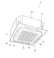
- FIG. 2 shows an external perspective view of the indoor unit 4.
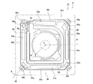
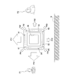
- FIG. 3 is a schematic plan view showing a state in which the top plate 33a of the indoor unit 4 is removed.
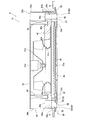
- FIG. 4 is a schematic side cross-sectional view of the indoor unit 4 and corresponds to a cross-sectional view taken along the line AOA in FIG.
- the indoor unit casing 31 includes a casing body 31a, a decorative panel 32, a wind direction adjusting unit 70, and the like. As shown in FIGS. 3 and 4, the casing main body 31 a is arranged so as to be inserted into an opening formed in the ceiling U of the air conditioning chamber. In the plan view, the long side and the short side are alternately arranged. Is a substantially octagonal box-like body, and the lower surface is open.
- the casing main body 31a includes a substantially octagonal top plate 33a in which long sides and short sides are alternately and continuously formed, a side plate 34 extending downward from the peripheral edge of the top plate 33a, and the top plate 33a and the side plate. And a bottom plate 33b that supports 34 from below.
- the side plate 34 includes side plates 34a, 34b, 34c, 34d corresponding to the long sides of the top plate 33a, and side plates 34e, 34f, 34g, 34h corresponding to the short sides of the top plate 33a.
- the side plate 34h is penetrated by a liquid side connection pipe 5a and a gas side connection pipe 6a for connecting the indoor heat exchanger 42 and the refrigerant communication pipes 5 and 6.
- FIG. 5 which is a bottom view of the bottom plate 33b with no decorative panel 32 or the like attached thereto, a substantially rectangular opening is provided at the center, and a plurality of openings are provided around the opening.
- the lower surface of 31a is comprised.
- the bottom plate 33 b is formed so as to extend outward from the top plate 33 a and the side plate 34, and the decorative panel 32 is attached to the lower surface side (indoor side).
- the casing body 31a surrounds the suction passage 35a for taking air into the casing body 31a from the suction port 35 and the outside of the suction passage 35a.
- Each of the outlet channels 51a, 52a, 53a, 54a, 61a, 62a, 62a, 63a, and 64a is provided for blowing the conditioned air into the room.
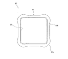
- the decorative panel 32 is disposed so as to be fitted into the opening of the ceiling U, and is a plate having a substantially quadrangular shape in plan view. By being attached to the bottom plate 33b of the main body 31a from the indoor side, it is fixed to the lower end of the casing main body 31a. As shown in FIG.
- the decorative panel 32 includes a suction grill 32 a, an inner frame decorative panel 37, and an outer frame decorative panel 38, and has a suction port 35 and an outlet 36. is doing.
- the lower end of the inner frame decorative panel 37 is arranged to be located slightly below the lower end of the outer frame decorative panel 38.
- the suction grill 32a is a substantially rectangular panel disposed in the center of the lower surface of the casing body 31a.
- the inner frame decorative panel 37 is a substantially rectangular frame member, and is disposed between the suction port 35 and the air outlet 36.
- An inner edge 37i of the inner frame decorative panel 37 has a substantially quadrangular shape, and has a rounded corner.
- the outer edge of the inner frame decorative panel 37 includes an inner frame outlet side straight portion 37a, an inner frame outlet side curved portion 37b, an opening inner bulging portion 37c, and the like.
- the inner frame outlet side straight portion 37a is provided at an outer position corresponding to the vicinity of the center of each of the four sides of the inner edge 37i, is substantially parallel to the side of the inner edge 37i, and extends linearly. It is a part.
- the inner frame blower outlet side curved portion 37b is formed such that the edge is located on the outer side as it approaches the corner of the inner frame decorative panel 37, and has a concave shape that is gently depressed toward the inner side.
- the opening inner bulging portion 37c forms an outer edge near the corner of the inner frame decorative panel 37, and each corner has a rounded shape and bulges outward.
- the outer frame decorative panel 38 is disposed so as to cover the outer edge of the lower surface of the casing main body 31 a and is disposed outside the air outlet 36.
- the outer edge 38j of the outer frame decorative panel 38 is substantially rectangular and has a shape along the edge of the bottom plate 33b of the casing body 31a. The corners are rounded.
- the inner edge of the outer frame decorative panel 38 includes an outer frame outlet side straight portion 38d, an outer frame outlet side curved portion 38e, and the like.
- the outer frame outlet side straight portion 38d is provided at an inner position corresponding to the vicinity of the center of each of the four sides of the outer edge 38j, is substantially parallel to the side of the outer edge 38j, and extends linearly.
- the outer frame outlet-side curved portion 38e is formed such that the edge is located on the inner side as it approaches the corner of the outer frame decorative panel 38, and has a convex shape that gently swells toward the outer side.
- the straight part of the outer frame outlet side straight part 38d is formed to be shorter than the straight part of the inner frame outlet side straight part 37a, and the outer frame outlet side curved part of the inner frame. Since the ratio of 38e is large, the bottom view of the outer frame outlet side straight portion 38d and the outer frame outlet side curved portion 38e has a shape close to a circle.
- the suction port 35 is a substantially quadrangular opening provided substantially at the center of the suction grill 32a.
- the suction port 35 is provided with a filter 39 for removing dust in the air sucked from the suction port 35.
- the suction passage 35a is connected to the inside of the casing body 31a of the suction port 35.
- the air outlet 36 is provided between the inner frame decorative panel 37 and the outer frame decorative panel 38 so as to surround the suction port 35, and includes a long side air outlet 50 and a short side air outlet 60. Has been.
- the long-side air outlet 50 includes a first long-side air outlet 51, a second long-side air outlet 52, a third long-side air outlet 53, which are provided at positions corresponding to the respective sides of the suction port 35 in a substantially square shape.
- the fourth long-side air outlet 54 is composed of four air outlets.
- the long side outlet 50 is formed so as not to have an edge portion toward the inside of the opening.
- the long-side outlet 50 has a smaller length difference between the longitudinal direction and the width direction, which is a direction perpendicular to the longitudinal direction, than the conventional outlet (the aspect ratio of the length is smaller than that of the conventional one). Therefore, the air flow bundle of the air flow blown out from the vicinity of the center of the long side outlet 50 can be thickened to easily maintain the initial velocity.
- the short side outlet 60 includes a first short side outlet 61, a second short side outlet 62, a third short side outlet 63 provided at positions corresponding to the corner portions of the substantially rectangular shape of the suction port 35, and
- the fourth short side air outlet 64 is composed of four air outlets.
- the blower outlet 36 is arranged in a substantially annular shape, with the long side blower outlets 50 and the short side blower outlets 50 arranged alternately.
- the first long-side outlet 51, the second long-side outlet 52, the third long-side outlet 53, and the fourth long-side outlet 54 have a first long-side outlet channel 51a and a second long-side outlet, respectively.
- the blowing channel 52a, the third long side blowing channel 53a, and the fourth long side blowing channel 54a are connected.
- the first short side outlet 61, the second short side outlet 62, the third short side outlet 63, and the fourth short side outlet 64 have a first short side outlet 61a and a second short side, respectively.
- the blowing channel 62a, the third short side blowing channel 63a, and the fourth short side blowing channel 64a are connected.
- the air direction adjusting unit 70 has a shape that is long in the rotational axis direction.
- the air direction adjusting unit 70 It functions as a wind direction adjusting plate that adjusts the wind direction of conditioned air blown into the air-conditioned room.
- the air direction adjusting unit 70 is not disposed in the short-side outlet 60 of the outlet 36 but is disposed only in the long-side outlet 50.
- the wind direction adjusting unit 70 adjusts the wind direction of the conditioned air blown from the first long side blower outlet 52 and the first wind direction adjuster 71 that adjusts the wind direction of the conditioned air blown from the first long side blower outlet 51.
- the second wind direction adjusting unit 72, the third wind direction adjusting unit 73 for adjusting the wind direction of the conditioned air blown out from the third long side outlet 53, and the wind direction of the conditioned air blown out from the fourth long side outlet 54 A fourth wind direction adjusting unit 74 for adjustment is provided.
- the wind direction adjusting unit 70 includes a flap body 80 and an arm 90 including a rotation shaft 90x.
- the flap body 80 is a plate-like member formed to extend in a direction substantially parallel to the rotation shaft 90x, and the surface 80x is a surface opposite to the back surface 80y that is the surface on which the arm 90 is attached. However, it has a curved shape protruding outward.
- the outer edge of the flap body 80 is formed so as not to have a shape portion that is recessed inward.
- the flap body 80 is provided so that the distance from the rotation shaft 90 x becomes shorter as it approaches the indoor side in a state where the surface 80 x is mainly directed to the indoor side (downstream side of the blown air flow).
- the distance from the rotating shaft 90x becomes longer as it moves away from the indoor side (towards the upstream side of the blown air flow).
- trajectory different in the one end and the other end of the flap main body 80 will be followed.
- the surface 80x of the flap body 80 is uneven so as to extend in the longitudinal direction of the flap body 80 in the vicinity of the outer end in a state where the surface 80x mainly faces the downstream side of the blown air flow.
- a shape portion 80xa is provided.
- the surface 80x of the flap body 80 is configured by a smooth, substantially flat surface except for the portion where the uneven portion 80xa is provided.
- a flocked sheet 80ya on which a mixture of short fibers having different pile lengths is evenly flocked is attached to the back surface 80y of the flap body 80.
- the flocked sheet 80ya is a portion to which conditioned air from the inside of the casing body 31a hits when adjusting the blowing air direction in a state where the surface 80x of the flap body 80 mainly faces the downstream side of the blowing air flow. The occurrence of condensation in can be suppressed.
- the flocking sheet 80ya is provided slightly inwardly in a state where the surface 80x mainly faces the downstream side of the blown air flow, and flocking is performed in the thickness direction of the flap body 80.
- the portion where the sheet 80ya and the concavo-convex shape portion 80xa overlap is provided to be small.
- the outer peripheral shape of the flap body 80 is the flap inner straight portion 80a, the flap inner curved portion 80b, the flap longitudinal direction end portion 80c, and the flap outer straight line. It consists of a portion 80d, a flap outer curved portion 80e, and the like.
- the flap inner straight portion 80a is located on the inner side of the flap main body 80 with the surface 80x of the flap main body 80 facing the indoor side, and is an edge of a linear portion extending substantially parallel to the direction of the rotation axis 90x. .
- the flap inner straight portion 80 a is provided near the center in the direction of the rotation axis 90 x of the flap body 80 and occupies about 50% of the length of the flap body 80 in the longitudinal direction.
- the flap inner curved portion 80b is an edge that gently connects each flap longitudinal direction end portion 80c from both ends of the flap inner straight portion 80a, and has a shape that gently swells outside the flap body 80.
- the flap inner curved portion 80b occupies about 25% of the end of the flap body 80 in the longitudinal direction.
- the flap longitudinal direction end portion 80c is located on the flap outer straight portion 80d side in the width direction perpendicular to the rotation axis 90x direction, that is, in the direction perpendicular to both the flap inner straight portion 80a and the flap outer straight portion 80d.
- the distance in the width direction between the flap longitudinal end portion 80c and the flap inner straight portion 80a is the distance between the flap longitudinal end portion 80c and the flap outer straight portion 80d. It is provided to be longer than the distance in the width direction.
- the flap outer straight portion 80d is located on the outer side of the flap main body 80 with the surface 80x of the flap main body 80 facing the indoor side, and is an edge of a linear portion extending substantially parallel to the direction of the rotation axis 90x. .
- the flap outer straight portion 80d is also provided near the center of the rotation shaft 90x of the flap body 80, but is formed shorter than the length of the flap inner straight portion 80a.
- the flap outer curved portion 80e is an edge that connects each flap longitudinal end 80c more rapidly than the flap inner curved portion 80b from both ends of the flap outer straight portion 80d, and has a shape that gently swells outward. ing.
- the arm 90 extends in the vicinity of both ends in the longitudinal direction of the flap body 80 in a direction away from the back surface 80 y of the flap body 80 to a portion exceeding the rotation axis 90 x. That is, the length of the arm 90 is longer than the distance D from the back surface 80y of the flap body 80 to the rotating shaft 90x, as shown in FIG.
- the arm 90 extends so as to be inclined slightly toward the outer frame decorative panel 38 rather than the plate thickness direction of the flap body 80 in a state in which most of the surface 80x of the flap body 80 is visible in the bottom view of the casing body 31a. ing. As shown in FIG.
- a shaft member 90a extending along the rotation shaft 90x is provided in the vicinity of the end of the arm 90 opposite to the end of the flap body 80.
- the arm 90 extends from the lower side of the back surface 80y of the flap body 80 with the front surface 80x of the flap body 80 facing the indoor side, and has a width in the vicinity of the center of the flap body 80 in the longitudinal direction. On the other hand, it has a width of about 30%.
- the indoor fan 41 is a centrifugal blower arranged inside the casing body 31a.
- the indoor fan 41 sucks indoor air into the casing body 31 a through the suction port 35 of the decorative panel 32, and forms an air flow that blows out of the casing body 31 a through the outlet 36 of the decorative panel 32.
- the indoor fan 41 includes a fan motor 41a provided at the center of the top plate 33a of the casing body 31a, and an impeller 41b that is connected to the fan motor 41a and is driven to rotate.
- the impeller 41b is an impeller having turbo blades.
- the indoor heat exchanger 42 is a finned tube heat exchanger that is bent so as to surround the periphery of the indoor fan 41 in a plan view and is arranged inside the casing body 31a. More specifically, the indoor heat exchanger 42 includes a large number of heat transfer fins arranged at predetermined intervals, and a plurality of heat transfer tubes provided in a state of penetrating these heat transfer fins in the plate thickness direction. It is a fin tube type heat exchanger called a cross fin type.
- the liquid side of the indoor heat exchanger 42 is connected to the liquid refrigerant communication tube 5 via the liquid side connection tube 5a.
- the gas side of the indoor heat exchanger 42 is connected to the gas refrigerant communication pipe 6 via the gas side connection pipe 6a.
- the indoor heat exchanger 42 functions as a refrigerant evaporator during cooling and as a refrigerant condenser during heating. As a result, the indoor heat exchanger 42 can exchange heat with the air blown from the indoor fan 41, cools the air during cooling, and heats the air during heating.
- the drain pan 40 is disposed below the indoor heat exchanger 42 and receives drain water generated by condensation of moisture in the air in the indoor heat exchanger 42.
- the drain pan 40 is attached to the lower part of the casing body 31a.
- the drain pan 40 is formed with a blow hole 40a, a suction hole 40b, and a drain water receiving groove 40c.
- the blowout holes 40a are formed at various locations so as to communicate with the blowout port 36 of the decorative panel 32.
- the suction hole 40 b is formed so as to communicate with the suction port 35 of the decorative panel 32.
- the drain water receiving groove 40 c is formed below the indoor heat exchanger 42.
- the bell mouth 41c is disposed so as to correspond to the inside of the suction hole 40b of the drain pan 40, and guides the air sucked from the suction port 35 to the impeller 41b of the indoor fan.
- the control unit 7 includes an outdoor control unit 7a that controls various components of the outdoor unit 2, an indoor control unit 7b that controls various components of the indoor unit 4, and setting inputs from the user. It has a controller 7c for receiving.
- the control unit 7 includes four outlets including a first long-side outlet 51, a second long-side outlet 52, a third long-side outlet 53, and a fourth long-side outlet 54 among the outlets 36.
- the wind direction of the conditioned air blown out from the first wind direction adjusting unit 71, the second wind direction adjusting unit 72, the third wind direction adjusting unit 73, and the fourth wind direction adjusting unit 74 is rotated for each wind direction adjusting unit 70 independently.
- Independent wind direction control that adjusts each independently by performing control to change the first wind direction adjusting unit 71, second wind direction adjusting unit 72, third wind direction adjusting unit 73, and fourth wind direction adjusting unit 74 are interlocked.
- interlocking wind direction control is performed in which the control is performed in association with each other by performing control so that the posture is in the same rotational state.
- the controller 7c has an input button or the like, and can receive an instruction from the user to perform independent wind direction control or linked wind direction control. And the control part 7 performs the said independent wind direction control or the interlocking wind direction control according to the instruction
- the control unit 7 includes a first long side air outlet 51, a second long side air outlet 52, a third long side air outlet 53, and a fourth length.
- the rotation states of the wind direction adjusting units 70 of the first wind direction adjusting unit 71, the second wind direction adjusting unit 72, the third wind direction adjusting unit 73, and the fourth wind direction adjusting unit 74 are individually independent.
- the individual air volume suppression control for reducing the air flow volume from the specific long side air outlets 51 to 54 is performed by changing the posture by adjusting the air volume.
- the controller 7c is instructed to perform the individual air volume suppression control, and the specific long-side air outlet 50 selected to suppress the air outlet air volume of the long-side air outlets 50. Can be received from the user. Then, when the controller 7c receives an instruction for the individual air volume suppression control, the control unit 7 causes the specific long-side blowing so that the blowing air volume from the specific long-side air outlet 50 is reduced most.
- the individual air volume suppression control is performed by rotating the wind direction adjusting unit 70 disposed at the position of the outlet 50.
- the control unit 7 maintains the individual air volume suppression control for the specific long-side outlet 50 received first and second, and then the specific long-side outlet 50 received by the controller 7c. Ignore the setting input for the individual airflow suppression control.
- the individual air volume suppression control can be performed for another long side air outlet 50.
- Cooling Operation In the refrigerant circuit 10 during cooling, the four-way switching valve 22 is in the state indicated by the solid line in FIG. Further, the liquid side closing valve 25 and the gas side closing valve 26 are opened, and the opening of the expansion valve 24 is adjusted so as to depressurize the refrigerant. In the state of the refrigerant circuit 10, the low-pressure gas refrigerant is sucked into the compressor 21, is compressed by the compressor 21, becomes high-pressure gas refrigerant, and is discharged from the compressor 21.
- This high-pressure gas refrigerant is sent to the outdoor heat exchanger 23 through the four-way switching valve 22, exchanges heat with outdoor air in the outdoor heat exchanger 23, and is condensed to become a high-pressure liquid refrigerant.
- This high-pressure liquid refrigerant is sent to the expansion valve 24, where it is decompressed and becomes a low-pressure gas-liquid two-phase refrigerant.
- This low-pressure gas-liquid two-phase refrigerant is sent to the indoor heat exchanger 42 through the liquid side shut-off valve 25, the liquid refrigerant communication pipe 5 and the liquid side connection pipe 5a, and from the indoor fan 41 in the indoor heat exchanger 42. It exchanges heat with the blown air and evaporates to become a low-pressure gas refrigerant.
- This low-pressure gas refrigerant is sent again to the compressor 21 through the gas side connection pipe 6 a, the gas refrigerant communication pipe 6, the gas side closing valve 26 and the four-way switching valve 22.
- the four-way switching valve 22 is in the state indicated by the broken line in FIG. Further, the liquid side closing valve 25 and the gas side closing valve 26 are opened, and the opening of the expansion valve 24 is adjusted so as to depressurize the refrigerant.
- the low-pressure gas refrigerant is sucked into the compressor 21, is compressed by the compressor 21, becomes high-pressure gas refrigerant, and is discharged from the compressor 21.
- the high-pressure gas refrigerant is sent to the indoor heat exchanger 42 through the four-way switching valve 22, the gas-side shutoff valve 26, the gas refrigerant communication pipe 6 and the gas-side connection pipe 6 a, and the indoor fan 41 in the indoor heat exchanger 42. Heat is exchanged with the air blown out from the air to condense into a high-pressure liquid refrigerant.
- the high-pressure liquid refrigerant is sent to the expansion valve 24 through the liquid-side connecting pipe 5a, the liquid-refrigerant communication pipe 5, and the liquid-side closing valve 25, and is decompressed by the expansion valve 24 to be a low-pressure gas-liquid two-phase refrigerant. Become.
- This low-pressure gas-liquid two-phase refrigerant is sent to the outdoor heat exchanger 23 and exchanges heat with outdoor air in the outdoor heat exchanger 23 to evaporate into a low-pressure gas refrigerant.
- This low-pressure gas refrigerant is sent again to the compressor 21 through the four-way switching valve 22.
- FIG. 11 shows a partially enlarged external view in bottom view in the vicinity of the first long-side outlet 51.
- a first wind direction adjusting unit 71 and a wind direction adjusting drive unit 95 are disposed inside the first long side outlet 51.
- the wind direction adjusting drive unit 95 is provided inside both ends in the longitudinal direction of the first long-side outlet 51 and outside both ends in the longitudinal direction of the first wind direction adjusting unit 71.
- the wind direction adjusting drive unit 95 is connected to the first wind direction adjusting unit 71 via a shaft member 90a extending from the arm 90 of the first wind direction adjusting unit 71 along the rotation axis 90x.
- a driving force for rotating the adjusting unit 71 is applied.
- the wind direction adjusting drive unit 95 and the shaft member 90 a of the first wind direction adjusting unit 71 constitute a cam mechanism (not shown), and the control unit 7 performs the first operation on the wind direction adjusting drive unit 95.
- Drive control via the cam mechanism is performed by sending a control signal for controlling the drive state of the wind direction adjusting unit 71.
- the first long side air outlet 51 has an outer edge formed by the outer frame decorative panel 38, an inner edge formed by the inner frame decorative panel 37, and a longitudinal end portion formed by the inner side surface of the wind direction adjusting drive unit 95. It is configured.
- variety in the edge part (inner side surface of the wind direction adjustment drive part 95) of the longitudinal direction of the 1st long side outlet 51 becomes about 60% of the width
- the inner edge of the first long side air outlet 51 is constituted by an inner frame air outlet side straight portion 37a, an inner frame air outlet side curved portion 37b, and the like of the inner frame decorative panel 37.
- the 1st long side blower outlet 51 has the shape which swelled slightly toward the inner side, slightly bulging toward the outer side in bottom view.
- the bulge to the inner side of the 1st long side blower outlet 51 is formed so that it may become larger than the bulge to the outer side.
- the outer frame air outlet side straight line portion 38 d of the outer frame decorative panel 38 is located in the vicinity of the center of the first long side air outlet 51 in the longitudinal direction.
- the outer frame air outlet side curved portion 38e of the outer frame decorative panel 38 is located in the vicinity of both ends in the longitudinal direction of the first long side air outlet 51 and in the vicinity of the outside of the wind direction adjusting drive unit 95.
- the inner frame air outlet side straight portion 37 a of the inner frame decorative panel 37 is located near the center of the first long side air outlet 51 in the longitudinal direction.
- the inner frame air outlet side curved portion 37b of the inner frame decorative panel 37 is slightly closer to the inner side than both longitudinal ends of the first long side air outlet 51, and inside the wind direction adjusting drive unit 95 and the wind direction adjusting drive unit 95.
- the horizontal width of the outer frame air outlet side straight portion 38d and the outer frame air outlet side curved portion 38e of the outer frame decorative panel 38 constituting the edge is in the longitudinal direction of the first long-side air outlet 51. It is arrange
- the horizontal width of the inner frame air outlet side straight portion 37a, the inner frame air outlet side curved portion 37b, etc. of the frame decorative panel 38 is generally the same in the longitudinal direction of the first long side air outlet 51 (about approximately). 1 cm) so that the edges of each other are along.
- the width between the inner edge of the flap body 80 of the first wind direction adjusting portion 71 and the inner edge of the first long-side outlet 51 is equal to the outer edge of the flap body 80 of the first wind direction adjusting portion 71.
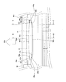
- FIG. 12 is a schematic cross-sectional view taken along the line BB in FIG. 11 near the first long-side outlet 51.
- the posture of the wind direction adjusting unit 70 shown in FIG. 12 is also an example of the posture of the flap body 80 when the above-described independent wind direction control or interlocking wind direction control is performed.
- the first long side outlet passage 51 a extends from the first long side outlet 51 toward the upstream side of the air flow.
- the inner wall surface of the first long-side outlet channel 51a in the vicinity of the first long-side outlet 51 is constituted by the bottom plate 33b of the casing body 31a.
- the inner wall surface of the first long side outlet channel 51a has a curved shape such that the center of the radius of curvature is located on the rotating shaft 90x side as shown in FIG. It is formed so as to be located on the outer side as it approaches the first long side outlet 51.
- the outer wall surface of the first long side outlet channel 51a is positioned so that the center of the radius of curvature is located on the opposite side of the rotary shaft 90x as shown in FIG. It has a curved shape so that the interval between the inner wall surfaces is maintained, and is formed so as to be positioned on the outer side as it approaches the first long-side outlet 51.
- the inclination angle ⁇ 11 of the inner wall surface and the outer wall surface at the first long-side outlet 51 portion at the end in the blowing direction is inclined about 40 degrees with respect to the horizontal direction. The blown air can be guided to the outside.
- the rotary shaft 90x is located upstream of the first long side outlet 51 located at the end of the first long side outlet passage 51a in the air flow direction. Moreover, this rotating shaft 90x is arrange
- the arm 90 is located at the end of the first long-side outlet channel 51a even in the rotational state closest to the first long-side outlet 51 in the rotational state of the first wind direction adjusting unit 71. It is located at a position substantially overlapping with the air outlet 51 or on the upstream side of the air flow. As shown in FIG.
- the length in the width direction in the vicinity of the center of the flap body 80 is a line connecting the rotation shaft 90 x and one end side in the width direction of the flap body 80, and the width direction of the rotation shaft 90 x and the flap body 80.
- the angle ⁇ ⁇ b> 1 formed by the line connecting the other end side is set to about 135 degrees.
- FIG. 13 is a schematic sectional view taken along the line CC in FIG. 11 near the first long-side outlet 51.
- the inner wall surface of the first long-side outlet channel 51a is formed so as to be positioned on the outer side as it approaches the first long-side outlet 51 as shown in FIG.
- the shape is flat and different from the curved shape in the vicinity of the center described above.
- the outer wall surface of the first long-side outlet channel 51a is the same as the inner wall surface, and approaches the first long-side outlet 51 as shown in FIG. Accordingly, the planar shape is formed so as to be located on the outside, which is different from the curved shape in the vicinity of the center described above.
- the shapes of the inner wall surface and the outer wall surface of the first long side outlet channel 51a are the shape in the vicinity of the center in the longitudinal direction of the flap body 80 and the shape in the vicinity of the end in the longitudinal direction of the flap body 80. It is formed so as to change gradually according to the position in the longitudinal direction.
- the inclination angle ⁇ 21 of the inner wall surface and the outer wall surface in the first long side outlet 51 portion at the end in the blowing direction is about 55 degrees with respect to the horizontal direction. It is inclined so that the blown air can be guided downward.
- the length in the width direction in the vicinity of the end of the flap body 80 is a line connecting the rotation shaft 90 x and one end side in the width direction of the flap body 80, and the width of the rotation shaft 90 x and the flap body 80.
- the angle ⁇ 2 formed by the line connecting the other end side in the direction is set to be about 75 degrees.
- the length in the width direction near the end of the flap body 80 is configured to be about 40% of the length in the width direction near the center of the flap body 80.
- the control unit 7 sends a control signal to the wind direction adjustment drive unit 95, and all of the wind direction adjustment units 70, that is, the first wind direction adjustment unit 71, the second wind direction adjustment unit 72, the third wind direction adjustment unit 73, and the fourth wind direction adjustment unit 74.
- the center of the surface 80x is adjusted to be substantially vertically downward by rotating.
- FIG. 14 shows an image diagram of airflow suppression control.
- the control unit 7 When the controller 7c receives an instruction from the user to suppress the amount of air blown from the specific long-side outlet 50, the control unit 7 includes the specific long side instructed by the user in the wind direction adjusting drive unit 95.
- a control signal is sent to a wind direction adjustment drive unit 95 that controls the rotation state of the wind direction adjustment unit 70 provided at a position corresponding to the outlet 50.
- the wind direction adjustment drive unit 95 that has received the control signal rotates the wind direction adjustment unit 70 that controls the rotation state of the wind direction adjustment drive unit 95, and reduces the amount of air blown from the long side outlet 50 specified by the user. Adjust to a restricted posture. For example, as shown in FIG.
- the control unit 7 performs the above-described individual air volume suppression control, thereby reducing the amount of the air flow F53 that is blown out from the third long-side outlet 53 toward the wall surface W side.
- the amount of the air flow F52 blown out from the second long side outlet 52 toward the P2 side is also reduced.
- the instruction by the user P2 includes a case where desiring to reduce the draft feeling, a case where the user P2 feels that it is too cold or too hot due to cooling or heating, and the like.
- FIG. 15 is a cross-sectional view corresponding to the BB cut surface in FIG. 11 showing an example of the inclination state of the wind direction adjusting unit 70 during the individual air volume suppression control.
- the flap main body 80 on which the individual air volume suppression control is performed is adjusted by the wind direction adjusting drive unit 95 so that the surface 80x faces the upstream side of the first long-side outlet passage 51a. Specifically, it is adjusted by the wind direction adjusting drive unit 95 so that the inclination angle ⁇ 3 (inner angle) with respect to the horizontal plane of the portion near the center of the surface 80x is about 110 degrees (corresponding to FIG. 15).
- the inclination angle during the individual air volume suppression control is finely adjusted within the range of about plus 5 degrees and minus 5 degrees from the angle of about 110 degrees.
- the flap main body 80 can cover the whole circumference
- the air outlet 951 has a quadrangular shape
- the flap body 980 also has a quadrangular shape so as to correspond to the air outlet.
- the large air resistance from the wall surface of the blower outlet 951 has acted on the air flow blown from the center vicinity of the blower outlet 951.
- FIG. On the other hand, in the indoor unit 4 of the air conditioning apparatus 1 of this embodiment, it forms so that the width
- the air flow direction blown out from the vicinity of the center of the first long-side outlet passage 51a and the like is the first long-side outlet passage 51a and the like. It is in the direction along the ceiling U surface rather than the air flow direction blown out from the vicinity of the end.
- the air flow blown out from the vicinity of the center of the first long-side outlet passage 51a has a thick airflow bundle and the initial velocity is easily maintained. The turbulence of the airflow near the ceiling surface in the vicinity can be reduced. Thereby, the ceiling stain
- the length in the longitudinal direction of the long-side outlet 50 is shorter in the width direction than the vicinity of the center in the longitudinal direction of the long-side outlet 50. Since it is formed, the air flow is slow. In such a portion where the air flow is slow, air tends to convect along the surface of the ceiling U.
- the inclination angle of the wall surface in the vicinity of the outlet in the vicinity of the end portion in the longitudinal direction of the first long side outlet channel 51a and the like is the first long side outlet. It is formed to be tighter than the inclination angle of the wall surface near the outlet in the vicinity of the center in the longitudinal direction of the flow path 51a and the like. Thereby, the conditioned air blown from the vicinity of the end in the longitudinal direction of the long-side air outlet 50 is more away from the surface of the ceiling U than the conditioned air blown from the vicinity of the center of the long-side air outlet 50 in the longitudinal direction. (More vertically downward).
- contamination produced in the edge part vicinity of the long side blower outlet 50 can be suppressed.
- the airflow bundle of the air flow that passes through the vicinity of the center of the long-side air outlet 50 is thickened to easily maintain the initial velocity. For this reason, an increase in the distance in the width direction in the vicinity of the center of the long-side air outlet 50 is realized by bulging the long-side air outlet 50 closer to the suction port 35 side.
- the long side outlet 50 is formed so as to bulge inward, and the inner edge of the flap body 80 of the first air direction adjusting portion 71 and the first length.
- the width between the inner edge of the side outlet 51 is not more than half of the width between the outer edge of the flap body 80 of the first wind direction adjusting portion 71 and the outer edge of the first long-side outlet 51. It is comprised so that it may become.
- the long-side air outlet 50 has a shape in which the blown air velocity decreases as it approaches the end in the longitudinal direction, and a short circuit is likely to occur.
- the long side outlet 50 is formed such that the distance from the inlet 35 becomes longer as it goes toward the end in the longitudinal direction. For this reason, the short circuit which may arise in the end part vicinity of the longitudinal direction of the long side blower outlet 50 can be suppressed effectively.
- the indoor unit of the conventional air conditioning apparatus has a suction port 935, a blower outlet 951, and a flap 980 as shown in a bottom view of the decorative panel 932 shown in FIG.
- the blower outlet 951 has a blower outlet notch 951b formed so that the inner edge of the blower outlet 951 is suddenly depressed.
- the flap 980 has a flap notch 980b formed so that the outer edge of the flap 980 is suddenly depressed. In this case, the airflow is disturbed because the flow direction of the airflow in the flap notch portion 980b is different from the flow direction of the airflow in the portion other than the flap notch portion 980b, and the airflow is disturbed. Condensation may occur at the edge of the nearby outlet 951.
- the flap body 80 of the airflow direction adjusting unit 70 does not have a shape that cuts out the suction port 35 side in the vicinity of the end in the longitudinal direction.
- the degree of swelling on the suction port 35 side is increased so as to follow the shape of the long-side outlet 50.
- the flow direction of the airflow does not change abruptly, the turbulence of the airflow can be suppressed, and the occurrence of condensation can be reduced.
- the conventional air direction adjustment flap of the indoor unit has not been configured to cover the edge of the air outlet even when the operation is stopped, the user in the room is uneven between the air outlet and the air direction adjustment flap. The contents of the indoor unit could be seen through gaps, etc., and the design was poor.
- the indoor unit 4 of the air conditioner 1 of the present embodiment when the operation is stopped, the longest outlet 50 is covered with the widest area by the wind direction adjusting unit 70 in the bottom view of the indoor unit 4. Therefore, it is difficult for a user in the room to see the inside of the indoor unit 4.
- the outer edge of the flap body 80 is shaped along the edge of the long-side air outlet 50, and the unity between the decorative panel 32 and the wind direction adjusting unit 70 can be improved. Thereby, the designability of the indoor unit 4 when the operation is stopped can be improved.
- the long side outlet 50 and the short side outlet 60 are alternately arranged so as to surround the inlet 35. Thereby, conditioned air can be provided evenly around the indoor unit 4.
- the conditioned air is blown out by providing such a short-side outlet 60.
- the number of places and the total area are large, and the initial speed of conditioned air passing through the long-side air outlet 50 provided with the wind direction adjusting unit 70 may be reduced.
- the long side outlet 50 has a long side by adopting a shape in which the width near the center is expanded. The degree of decrease in the initial velocity of the conditioned air from the air outlet 50 can be kept small.
- the present invention is not limited to this. For example, if it is between 40% and 80%, a preferable effect can be obtained from the viewpoint of suppression of short circuit and design.
- B In the above embodiment, the case where the length in the width direction in the vicinity of the end of the flap body 80 is configured to be about 40% of the length in the width direction in the vicinity of the center of the flap body 80 is taken as an example. explained. However, the present invention is not limited to this, and for example, if it is between 20% and 60%, a preferable effect can be obtained from the viewpoint of suppression of short circuit and design.
- C In the embodiment described above, the indoor unit 4 that blows conditioned air in eight directions has been described as an example.
- the present invention is not limited to this, and, for example, the configuration in which the short side outlet 60 is not provided in the above-described embodiment may be configured with only four long side outlets 50. Also, there may be two outlets.
- the present invention is particularly useful in an indoor unit of an air conditioner because it can increase the reach distance of conditioned air blown out from a blower outlet while suppressing an increase in the size of the lower surface of the indoor unit and a short circuit. is there.
Abstract
Description
これに対して、吹出口の形状について、長手方向の長さに対する幅方向の長さを相対的に増大させることで、調和空気の遠方到達性を向上させることも考えられる。
しかし、幅方向の長さを増大させる場合には、室内機の下面の大型化を招いてしまう。
これに対しては、吹出口の形状を吸込口側に広げることで、室内機の下面の大型化を抑制させつつ、調和空気の遠方到達性を向上させることができる。
ところが、このように吹出口の形状を吸込口側に広げてしまうと、吹出口から吹き出された調和空気が、すぐに、近くの吸込口から吸入されてしまうというショートサーキットの問題が生じる。
この空気調和装置の室内機は、吹出口が吸込口側に膨らんで形成されているため、気流束を太くし、吹出口の中央近傍を通過する調和空気の初速度を維持しやすくすることにより、調和空気の到達距離を増大させることができる。そして、吹出口の膨らんでいる方向が、吸込口側であるため、室内機の下面の大型化を抑制させることができている。さらに、このように吹出口を吸込口側に膨らませたことにより吹出口と吸込口との距離は近づいてしまうが、風向調節部材の吸込口側の形状が、吹出口と同様に、吸い込み口側に膨らんだ形状となっているため、吹出口のうちの吸込口側の部分から吸込口に向かう空気流れを遮断しやすく、ショートサーキットを抑制させることができている。これにより、室内機の下面の大型化とショートサーキットとを抑制させながら、吹出口から吹き出される調和空気の到達距離を増大させることが可能になる。
一般に、吹出口の長手方向端部近傍は、長手方向中央近傍と比較して空気流れが遅く、天井面に沿うように空気が流れがちになる。
これに対して、この空気調和装置の室内機では、吹出口の長手方向端部近傍から吹き出される調和空気は、中央から吹き出される調和空気よりも、天井面から離れる方向に案内させることができている。これにより、天井汚れを抑制させることができる。
この空気調和装置の室内機は、風向調節部材がどのような方向を向いていても、吹出口の長手方向端部近傍から吹き出される空気流れ方向を、天井面から離れる方向に案内させることができるため、天井汚れ防止効果をより確実に得ることができる。
この空気調和装置の室内機は、吹出口の長手方向端部に向かうほど幅方向の長さが短く形成されているため、吹出口中央を通過する空気流れの気流束が太く、初速度をより維持しやすくすることができ、吹出口から吹き出される調和空気の到達距離をより効果的に増大させることが可能になる。
この空気調和装置の室内機は、吹出口が、端部よりも幅が広い直線形状部分を有しているため、調和空気の到達距離を増大させることができる。そして、風向調節部材についても同様の形状となっているため、このような吹出口を通過する調和空気の風向調節機能を確保することができる。これにより、風向調節機能を確保しつつ、調和空気の到達距離を増大させることが可能になる。
この空気調和装置の室内機は、吹出口は、長手方向端部に近づくほど吹き出し風速が低くなりショートサーキットを生じやすくなるが、長手方向端部に向かうにつれて吸込口との距離が遠くなるように形成されているため、ショートサーキットを抑制させつつ、吹出口の中央からの吹き出し気流束が太く、その初速度を維持しやすくすることで、吹出口から吹き出される調和空気の到達距離をより効果的に増大させることが可能になる。また、風向調節部材は、長手方向端部近傍において吸込口側を切り欠くような形状とすることなく、吹出口の形状と同様に、吸込口側の膨らみ度合いを上げている。このため、風向調節部材の長手方向端部近傍における吸込口側部分と、吹出口の長手方向端部近傍における吸込口側部分との間から漏れ出す空気が引き起こすショートサーキットを抑制させることができる。
この空気調和装置の室内機は、内側に窪んだ形状部分を有していないため、天井汚れをより効果的に防止することが可能になる。
この空気調和装置の室内機は、吹出口の吸込口側端部から、吸込口側に向けて流れるショートサーキットをより効果的に防止させることができ、吹出口と風向調節部材との形状関係について意匠性を向上させることもできる。
この空気調和装置の室内機は、調和空気を4方向に吹き出せるため、調和可能な対象空間を広く確保することができる。
この空気調和装置の室内機は、連続吹出口をさらに備えることで、室内機の周囲にまんべんなく調和空気を提供することが可能になる。そして、このように連続吹出口が設けられることで調和空気が吹き出される合計面積が大きくなると、風向調節部材が設けられた吹出口を通過する調和空気の初速度を維持しにくいおそれがあるが、その場合であっても、吹出口の形状について内側に膨らんだ形状を採用していることで、吹出口からの調和空気の初速度の低下程度を小さく抑えることが可能になる。
この空気調和装置の室内機は、空調運転の停止時には、吹出口の内部が風向調節部材によって隠されるため、室内機の中身が見えにくく、意匠性を向上させることができる。
第2発明の空気調和装置の室内機では、天井汚れを抑制させることができる。
第3発明の空気調和装置の室内機では、天井汚れ防止効果をより確実に得ることができる。
第4発明の空気調和装置の室内機では、吹出口から吹き出される調和空気の到達距離をより効果的に増大させることが可能になる。
第5発明の空気調和装置の室内機では、風向調節機能を確保しつつ、調和空気の到達距離を増大させることが可能になる。
第7発明の空気調和装置の室内機では、天井汚れをより効果的に防止することが可能になる。
第8発明の空気調和装置の室内機では、意匠性を向上させつつ、ショートサーキットを抑制させることができる。
第9発明の空気調和装置の室内機では、調和可能な対象空間を広く確保することができる。
第10発明の空気調和装置の室内機では、調和空気の到達距離の低下を抑えつつ、調和空気を周囲にまんべん無く供給することができる。
<1>空気調和装置1
図1は、本発明の一実施形態にかかる室内機が採用された空気調和装置1の概略構成図である。
空気調和装置1は、室内機のタイプが天井に埋め込まれることで設置されるタイプであり、8つの吹出口を有し、そのうち4つの吹出口に設けられた風向調節板の傾斜角度を風向調節板毎に独立して回動制御することができる。この空気調和装置1は、スプリットタイプの空気調和装置であり、主として、室外ユニット2、室内ユニット4、室外ユニット2と室内ユニット4とを接続する液冷媒連絡管5およびガス冷媒連絡管6、および、制御部7を有しており、蒸気圧縮式の冷媒回路10を構成している。
室外ユニット2は、室外等に設置されており、主として、圧縮機21、四路切換弁22、室外熱交換器23、膨張弁24、液側閉鎖弁25、ガス側閉鎖弁26、および、室外ファン27を有している。
圧縮機21は、低圧のガス冷媒を吸入し、圧縮して高圧のガス冷媒とした後に吐出するための圧縮機である。
四路切換弁22は、冷房と暖房との切換時に、冷媒の流れの方向を切り換えるための弁である。四路切換弁22は、冷房時には、圧縮機21の吐出側と室外熱交換器23のガス側とを接続するとともにガス側閉鎖弁26と圧縮機21の吸入側とを接続することが可能である(図1における四路切換弁22の実線を参照)。また、四路切換弁22は、暖房時には、圧縮機21の吐出側とガス側閉鎖弁26とを接続するとともに室外熱交換器23のガス側と圧縮機21の吸入側とを接続することが可能である(図1における四路切換弁22の破線を参照)。
膨張弁24は、冷房時には室外熱交換器23において凝縮された高圧の液冷媒を室内熱交換器42(後述)に送る前に減圧し、暖房時には室内熱交換器42において凝縮された高圧の液冷媒を室外熱交換器23に送る前に減圧することが可能な電動膨張弁である。
液側閉鎖弁25およびガス側閉鎖弁26は、外部の機器・配管(具体的には、液冷媒連絡管5およびガス冷媒連絡管6)との接続口に設けられた弁である。液側閉鎖弁25は、膨張弁24に接続されている。ガス側閉鎖弁26は、四路切換弁22に接続されている。
室外ファン27は、室外ユニット2の内部に配置され、室外空気を吸入して、室外熱交換器23に室外空気を供給した後に、ユニット外に排出する空気流れを形成する。このため、室外熱交換器23は、室外空気を冷却源又は加熱源として冷媒を凝縮や蒸発させる機能を有している。
室内ユニット4は、本実施形態において、天井埋込型と呼ばれる型式の天井設置型空気調和装置の室内機であり、室内機ケーシング31、室内ファン41、室内熱交換器42、ドレンパン40、および、ベルマウス41c等を有している。
図2に、室内ユニット4の外観斜視図を示す。図3に、室内ユニット4の天板33aを取り除いた状態を示す概略平面図を示す。図4に、室内ユニット4の概略側面断面図であり、図3中にA-O-Aで示す切断面における断面図に相当する。
室内機ケーシング31は、ケーシング本体31a、化粧パネル32、および、風向調節部70等から構成されている。
ケーシング本体31aは、図3および図4に示すように、空調室の天井Uに形成された開口に挿入されるようにして配置されており、その平面視において、長辺と短辺とが交互に形成された略8角形状の箱状体であり、下面が開口している。このケーシング本体31aは、長辺と短辺とが交互に連続して形成された略8角形状の天板33aと、天板33aの周縁部から下方に延びる側板34と、天板33aおよび側板34を下方から支える底板33bと、を有している。側板34は、天板33aの長辺に対応する側板34a、34b、34c、34dと、天板33aの短辺に対応する側板34e、34f、34g、34hとから構成されている。側板34hには、室内熱交換器42と冷媒連絡管5、6とを接続するための液側接続管5aおよびガス側接続管6aが、貫通している。底板33bは、化粧パネル32等が取り付けられていない状態の下面図である図5に示すように、中央に略四角形の開口が設けられ、その周囲に複数の開口が設けられており、ケーシング本体31aの下面を構成する。この底板33bは、図3に示すように、天板33aおよび側板34よりも外側に広がって形成されており、下面側(室内側)に化粧パネル32が取り付けられる。
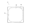
化粧パネル32は、図2、図3および図4に示すように、天井Uの開口に嵌め込まれるようにして配置されており、平面視が略4角形状の板状体であり、主として、ケーシング本体31aの底板33bに対して室内側から取り付けられることで、ケーシング本体31aの下端部に固定されている。化粧パネル32は、室内ユニット4の下面図である図6に示すように、吸込グリル32a、内枠化粧パネル37、および、外枠化粧パネル38によって構成され、吸込口35および吹出口36を有している。室内ユニット4の設置状態で、内枠化粧パネル37の下端は、外枠化粧パネル38の下端よりもやや下方に位置するように配置されている。
吹出口36は、内枠化粧パネル37と外枠化粧パネル38との間であって、吸込口35の周囲を取り囲むように設けられており、長辺吹出口50および短辺吹出口60から構成されている。長辺吹出口50は、吸込口35の略四角形状における各辺に対応する位置に設けられた第1長辺吹出口51、第2長辺吹出口52、第3長辺吹出口53、および、第4長辺吹出口54の4つの吹出口から構成されている。この長辺吹出口50は、開口の内側に向けて縁部分を有さないように形成されている。長辺吹出口50は、長手方向と、長手方向に直行する方向である幅方向と、の長さの差が従来の吹出口よりも小さくなるように(長さのアスペクト比が従来よりも小さくなるように)構成されているため、長辺吹出口50の中央近傍から吹き出される空気流れの気流束を太くし、初速度を維持しやすくすることができている。短辺吹出口60は、吸込口35の略四角形状における角部分に対応する位置に設けられた第1短辺吹出口61、第2短辺吹出口62、第3短辺吹出口63、および、第4短辺吹出口64の4つの吹出口から構成されている。吹出口36は、長辺吹出口50と短辺吹出口50とが交互に並べられながら、略環状に配置されている。なお、第1長辺吹出口51、第2長辺吹出口52、第3長辺吹出口53および第4長辺吹出口54には、それぞれ第1長辺吹出流路51a、第2長辺吹出流路52a、第3長辺吹出流路53a、第4長辺吹出流路54aが繋がっている。また、第1短辺吹出口61、第2短辺吹出口62、第3短辺吹出口63および第4短辺吹出口64には、それぞれ第1短辺吹出流路61a、第2短辺吹出流路62a、第3短辺吹出流路63a、第4短辺吹出流路64aが繋がっている。
風向調節部70は、軸方向視断面図である図9、および、主として室内側を向く面についての外観斜視図である図10において示すように、回転軸方向に長い形状を有しており、空調室内に吹き出される調和空気の風向を調節する風向調節板として機能する。風向調節部70は、本実施形態では、吹出口36のうち、短辺吹出口60には配置されることなく、長辺吹出口50にのみ配置されている。この風向調節部70は、第1長辺吹出口51から吹き出される調和空気の風向を調節する第1風向調節部71、第2長辺吹出口52から吹き出される調和空気の風向を調節する第2風向調節部72、第3長辺吹出口53から吹き出される調和空気の風向を調節する第3風向調節部73、および、第4長辺吹出口54から吹き出される調和空気の風向を調節する第4風向調節部74が設けられている。
フラップ本体80は、回転軸90xと略平行な方向に伸びて形成された板形状部材であって、アーム90が取り付けられている側の面である裏面80yとは反対側の面である表面80xが、外側に突出した湾曲形状を有している。フラップ本体80の外縁は、内側に向けて窪んだ形状部分を有さないように形成されている。フラップ本体80は、図9に示すように、表面80xが主として室内側(吹き出し空気流れ下流側)を向いている状態において、室内側に近づくにつれて回転軸90xとの距離が短くなるように設けられており、室内側にから離れるにつれて(吹き出し空気流れ上流側に向かうにつれて)回転軸90xとの距離が長くなるように設けられている。これにより、風向調節部70が回転した場合に、フラップ本体80の一端と他端とで異なる軌跡をたどることになる。フラップ本体80の表面80xには、図9に示すように、表面80xが主として吹き出し空気流れ下流側を向いている状態における外側端部近傍部分において、フラップ本体80の長手方向に伸びるようにして凹凸形状部80xaが設けられている。なお、フラップ本体80の表面80xは、この凹凸形状部80xaが設けられている部分以外は、なめらかな略平面によって構成されている。また、フラップ本体80の裏面80yには、パイル長さの異なる短繊維の混合物が均一に植毛してある植毛シート80yaが貼付されている。この植毛シート80yaは、フラップ本体80の表面80xが主として吹き出し空気流れ下流側を向いている状態で吹き出し風向を調節する際に、ケーシング本体31a内部からの調和空気が当たる部分であり、フラップ本体80における結露の発生を抑制させることができる。なお、この植毛シート80yaは、図9に示すように、表面80xが主として吹き出し空気流れ下流側を向いている状態において、わずかに内側寄りに設けられており、フラップ本体80の板厚方向において植毛シート80yaと凹凸形状部80xaが重なる部分が少なくなるように設けられている。
室内ファン41は、ケーシング本体31aの内部に配置された遠心送風機である。室内ファン41は、室内の空気を化粧パネル32の吸込口35を通じてケーシング本体31a内に吸入し、化粧パネル32の吹出口36を通じてケーシング本体31a外へ吹き出す空気流れを形成させる。室内ファン41は、ケーシング本体31aの天板33aの中央に設けられたファンモータ41aと、ファンモータ41aに連結されて回転駆動される羽根車41bとを有している。羽根車41bは、ターボ翼を有する羽根車であり、下方から羽根車41bの内部に空気を吸入し、平面視における羽根車41bの外周側に向かって吹き出すことができる。
室内熱交換器42は、平面視における室内ファン41の周囲を囲むように曲げられて、ケーシング本体31aの内部に配置されたフィンチューブ型熱交換器である。より具体的には、室内熱交換器42は、所定間隔を空けて配置された多数の伝熱フィンと、これらの伝熱フィンを板厚方向に貫通した状態で設けられた複数の伝熱管とを有するクロスフィン型と呼ばれるフィンチューブ型熱交換器である。室内熱交換器42の液側は、上記のように、液側接続管5aを介して液冷媒連絡管5に接続されている。室内熱交換器42のガス側は、ガス側接続管6aを介してガス冷媒連絡管6に接続されている。そして、室内熱交換器42は、冷房時には、冷媒の蒸発器として、暖房時には、冷媒の凝縮器として機能するようになっている。これにより、室内熱交換器42は、室内ファン41から吹き出された空気と熱交換を行って、冷房時には空気を冷却し、暖房時には空気を加熱することができるようになっている。
ベルマウス41cは、ドレンパン40の吸入孔40bの内側に対応するように配置されており、吸込口35から吸入される空気を室内ファンの羽根車41bへと導く。
<1-3>制御部7
制御部7は、図1に示すように、室外ユニット2の各種構成機器を制御する室外制御部7a、室内ユニット4の各種構成機器を制御する室内制御部7b、および、ユーザからの設定入力を受け付けるためのコントローラ7cを有している。
次に、冷房運転および暖房運転における空気調和装置1の動作について説明する。
<2-1>冷房動作
冷房時における冷媒回路10は、四路切換弁22が図1の実線で示される状態となっている。また、液側閉鎖弁25、ガス側閉鎖弁26は開状態にされ、膨張弁24は冷媒を減圧するように開度調節される。
この冷媒回路10の状態において、低圧のガス冷媒は、圧縮機21に吸入されて、圧縮機21において圧縮されて高圧のガス冷媒となって、圧縮機21から吐出される。この高圧のガス冷媒は、四路切換弁22を通じて室外熱交換器23に送られて、室外熱交換器23において室外空気と熱交換を行って凝縮して高圧の液冷媒となる。この高圧の液冷媒は、膨張弁24に送られて、膨張弁24において減圧されて低圧の気液二相状態の冷媒となる。この低圧の気液二相状態の冷媒は、液側閉鎖弁25、液冷媒連絡管5および液側接続管5aを通じて室内熱交換器42に送られて、室内熱交換器42において室内ファン41から吹き出される空気と熱交換を行って蒸発して低圧のガス冷媒となる。この低圧のガス冷媒は、ガス側接続管6a、ガス冷媒連絡管6、ガス側閉鎖弁26および四路切換弁22を通じて圧縮機21に再び送られる。
次に、暖房時における冷媒回路10は、四路切換弁22が図1の破線で示される状態となっている。また、液側閉鎖弁25、ガス側閉鎖弁26は開状態にされ、膨張弁24は冷媒を減圧するように開度調節される。
この冷媒回路10の状態において、低圧のガス冷媒は、圧縮機21に吸入されて、圧縮機21において圧縮されて高圧のガス冷媒となって、圧縮機21から吐出される。この高圧のガス冷媒は、四路切換弁22、ガス側閉鎖弁26、ガス冷媒連絡管6およびガス側接続管6aを通じて室内熱交換器42に送られて、室内熱交換器42において室内ファン41から吹き出される空気と熱交換を行って凝縮して高圧の液冷媒となる。この高圧の液冷媒は、液側接続管5a、液冷媒連絡管5および液側閉鎖弁25を通じて膨張弁24に送られて、膨張弁24において減圧されて低圧の気液二相状態の冷媒となる。この低圧の気液二相状態の冷媒は、室外熱交換器23に送られて、室外熱交換器23において室外空気と熱交換を行って蒸発して低圧のガス冷媒となる。この低圧のガス冷媒は、四路切換弁22を通じて圧縮機21に再び送られる。
ここでは、第1長辺吹出口51の近傍における第1風向調節部71の配置を述べる。なお、第2長辺吹出口52近傍、第3長辺吹出口53近傍および第4長辺吹出口54近傍については第1長辺吹出口51近傍と同様であるため、説明を省略する。
<3-1>下面視における配置関係
図11に、第1長辺吹出口51近傍における下面視部分拡大外観図を示す。
室内ユニット4の下面視において、第1長辺吹出口51の内側には、第1風向調節部71および風向調節駆動部95が配置されている。
風向調節駆動部95は、第1長辺吹出口51の長手方向の両端内側であって、第1風向調節部71の長手方向の両端外側に設けられている。この風向調節駆動部95は、第1風向調節部71のアーム90から回転軸90xに沿うように伸びている軸部材90aを介して、第1風向調節部71と接続されており、第1風向調節部71を回動させるための駆動力を与えている。具体的には、風向調節駆動部95と第1風向調節部71の軸部材90aとは、図示しないカム機構を構成しており、制御部7が、この風向調節駆動部95に対して第1風向調節部71の駆動状態を制御させるための制御信号を送ることで、カム機構を介した駆動制御が行われる。
内枠化粧パネル37の内枠吹出口側直線部37aは、第1長辺吹出口51の長手方向の中央近傍に位置している。内枠化粧パネル37の内枠吹出口側湾曲部37bは、第1長辺吹出口51の長手方向の両端よりもやや内側寄りであって、風向調節駆動部95の内側および風向調節駆動部95と第1風向調節部71との間近傍に位置している。
第1風向調節部71のフラップ本体80の外側の縁を構成しているフラップ内側直線部80a、フラップ内側湾曲部80bおよびフラップ長手方向端部80c等と、第1長辺吹出口51の外側の縁を構成している外枠化粧パネル38の外枠吹出口側直線部38dおよび外枠吹出口側湾曲部38e等との、水平方向の幅は、第1長辺吹出口51の長手方向に全般にわたって略同じ幅(約2cm)となるように配置されている。
なお、第1風向調節部71のフラップ本体80の内側の縁と第1長辺吹出口51の内側の縁との間の幅は、第1風向調節部71のフラップ本体80の外側の縁と第1長辺吹出口51の外側の縁との間の幅の半分以下となるように構成されている。
<3-2>風向調節部70の中央近傍における配置関係
図12に、第1長辺吹出口51近傍における、図11中のB-B切断面における概略断面図を示す。なお、図12に示す風向調節部70の姿勢は、上述した独立風向制御もしくは連動風向制御が行われている場合のフラップ本体80の姿勢の一例でもある。
アーム90は、第1風向調節部71の回転状態のうち最も第1長辺吹出口51に近づく回転状態においても、第1長辺吹出流路51aの端部に位置している第1長辺吹出口51と略重なる位置もしくは空気流れ上流側に位置している。
フラップ本体80の中央近傍における幅方向の長さは、図12に示すように、回転軸90xとフラップ本体80の幅方向の一端側とを結ぶラインと、回転軸90xとフラップ本体80の幅方向の他端側とを結ぶラインと、がなす角度θ1が135度程度となるように設けられている。
<3-3>風向調節部70の端部近傍における配置関係
図13に、第1長辺吹出口51近傍における、図11中のC-C切断面における概略断面図を示す。
フラップ本体80の長手方向の端部近傍では、第1長辺吹出流路51aの内側壁面は、図13に示すように、第1長辺吹出口51に近づくにつれて外側に位置するように形成された平面形状となっており、上述した中央近傍における湾曲形状とは異なっている。また、フラップ本体80の長手方向の端部近傍では、第1長辺吹出流路51aの外側壁面は、内側壁面と同様であり、図13に示すように、第1長辺吹出口51に近づくにつれて外側に位置するように形成された平面形状となっており、上述した中央近傍における湾曲形状とは異なっている。この第1長辺吹出流路51aの内側壁面および外側壁面の形状は、フラップ本体80の長手方向の中心近傍における形状と、フラップ本体80の長手方向の端部近傍における形状とが、フラップ本体80の長手方向の位置に応じて徐々に変化するように形成されている。なお、第1長辺吹出流路51aの端部近傍は、吹き出し方向端部の第1長辺吹出口51部分における内側壁面および外側壁面の傾斜角度θ21が、水平方向に対して55度程度に傾斜しており、向けて吹き出し空気をより下方に導くことができるようになっている。
<4>長辺吹出口50と風向調節部70との運転停止時の配置関係
ユーザからの運転停止(冷房動作や暖房動作等を行わない状態)の指示をコントローラ7cが受け付けると、制御部7は、上記風向調節駆動部95に制御信号を送り、風向調節部70の全て、すなわち、第1風向調節部71、第2風向調節部72、第3風向調節部73および第4風向調節部74のいずれについても、回動させることで、表面80xの中心が略鉛直下向きとなるように調節する。
<5>長辺吹出口50と風向調節部70との個別風量抑制制御時の配置関係
図14に、風量抑制制御のイメージ図を示す。
特定の長辺吹出口50から吹き出される風量を抑制する旨の指示をユーザからコントローラ7cが受け付けると、制御部7は、上記風向調節駆動部95のうち、ユーザによって指示された特定の長辺吹出口50に対応する位置に設けられた風向調節部70の回動状態を制御する風向調節駆動部95に向けて制御信号を送る。これにより、制御信号を受けた風向調節駆動部95は、自己が回動状態を制御する風向調節部70を回動させて、ユーザによって特定された長辺吹出口50から吹き出される空気量を制限させる姿勢に調節する。例えば、図14に示すように、室内ユニット4が室内の壁面Wの近くであってユーザP1およびユーザP2の近くに配置されている場合に、ユーザP2側に吹き出す空気量を抑制させる旨の指示をコントローラ7cが受け付けると、制御部7は、上述した個別風量抑制制御を行うことで、壁面W側へと第3長辺吹出口53から吹き出される空気流れF53の量を低減させつつ、ユーザP2側へと第2長辺吹出口52から吹き出される空気流れF52の量も低減させた状態とする。これにより、ユーザが存在していない壁面W側への調和空気の無駄な提供を低減させることができ、ユーザP2の望む風量を実現させることができる。例えば、ユーザP2による指示は、ドラフト感の低減を望んでいる場合や、冷房もしくは暖房によって冷え過ぎると感じたり暑過ぎると感じたりしている場合等が含まれる。
個別風量抑制制御が行われるフラップ本体80は、表面80xが、第1長辺吹出流路51aの空気流れ上流側に向いた状態となるように、風向調節駆動部95によって調節される。具体的には、表面80xのうちの中央近傍部分の水平面に対する傾斜角度θ3(内側の角度)が110度程度である状態(図15に相当)となるように、風向調節駆動部95によって調節される。これにより、個別風量抑制制御がされた長辺吹出口50からの吹き出し空気量を低減させることができる。なお、この個別風量抑制制御時の傾斜角度は、この110度程度の角度から、プラス5度程度およびマイナス5度程度の範囲内で、微調節される。
また、この個別風量抑制制御が行われた状態において、フラップ本体80の下方側の端部(図15中S2で示す部分)は、第1長辺吹出口51よりも、第1長辺吹出流路51aの空気流れ上流側に位置している。これにより、フラップ本体80は、室内ユニット4内部で温度調節された調和空気で周囲全体を概ね覆うことができ、温度調節されていない室内側の空気はフラップ本体80に触れにくくすることができる。このため、個別風量抑制制御によって長辺吹出口50からの吹き出し空気量が低減された状態でも、温度調節されていない室内空気がフラップ本体80に到達しにくくすることができ、フラップ本体80での結露の発生を抑制させることができている。
(1)
従来の空気調和装置の室内機は、例えば、図16に示す室内ユニット904のように、吹出口951が四角形状であり、フラップ本体980も吹出口に対応するように四角形状となっている。このため、吹出口951の中央近傍から吹き出される空気流れには吹出口951の壁面からの大きな空気抵抗が作用してしまっている。
これに対して、本実施形態の空気調和装置1の室内ユニット4では、長辺吹出口50の長手方向中央部分の幅が大きくなるように形成されている。このため、長辺吹出口50の中央近傍を通過して吹き出される空気流れの気流束を太くし、初速度を維持しやすくすることができ、調和空気の到達距離を増大させることができている。
本実施形態の空気調和装置1の室内ユニット4では、第1長辺吹出流路51a等の中央近傍では、第1長辺吹出流路51a等の端部近傍と比較して、吹き出し出口近傍における内側壁面および外側壁面の水平面に対する傾斜角度が小さくなるように構成されている。これにより、第1長辺吹出流路51a等の中央近傍から吹き出される空気を、より遠くへ到達させることができるようになっている。
(3)
従来の天井に埋め込まれるようにして設置され、調和空気の吹出口と天井面とが近接しているタイプの室内ユニットでは、調和空気を略水平方向に吹き出そうとすると天井面に沿うように気流が生じ、気流に沿うようにして天井面に汚れが生じやすい。特に、吹出口の長手方向の両端部近傍において、気流の乱れが生じ、汚れが顕著になることがあった。
(4)
本実施形態の空気調和装置1の室内ユニット4では、長辺吹出口50の長手方向端部近傍は、長辺吹出口50の長手方向の中央近傍と比較して、幅方向の長さが短く形成されているため、空気流れが遅い。このように空気流れが遅い部分では、天井Uの面に沿うように空気が対流しがちになる。
(5)
本実施形態の空気調和装置1の室内ユニット4では、上述のように、長辺吹出口50の中央近傍を通過して吹き出される空気流れの気流束を太くし、初速度を維持しやすくするための、長辺吹出口50の中央近傍の幅方向の距離の増大を、長辺吹出口50を吸込口35側に近づくように膨出して形成されることにより実現している。
(6)
本実施形態の空気調和装置1の室内ユニット4では、長辺吹出口50を内側に膨出させるように形成させており、第1風向調節部71のフラップ本体80の内側の縁と第1長辺吹出口51の内側の縁との間の幅が、第1風向調節部71のフラップ本体80の外側の縁と第1長辺吹出口51の外側の縁との間の幅の半分以下となるように構成されている。
このため、長辺吹出口50を内側に膨出させるように形成させたことに伴う吸い込み空気と吹き出し空気との間で生じうるショートサーキットを抑制させることができている。
(7)
本実施形態の空気調和装置1の室内ユニット4では、長辺吹出口50は、長手方向の端部に近づくほど吹き出し風速が小さくなって、ショートサーキットを生じやすい形状となっている。
(8)
従来の空気調和装置の室内機は、例えば、図17に示す化粧パネル932の下面視に示すような、吸込口935、吹出口951およびフラップ980を有している。吹出口951は、吹出口951の内側の縁が急激に窪むように形成された吹出口切り欠き部951bを有している。フラップ980は、フラップ980の外側の縁が急激に窪むように形成されたフラップ切り欠き部980bを有している。この場合、フラップ切り欠き部分980bにおける気流の流れ方向と、フラップ切り欠き部980b以外の部分における気流の流れ方向と、が異なることで気流が乱れており、フラップ切り欠き部分980bおよびその付近やその近傍の吹出口951の縁において結露が発生する場合がある。
(9)
従来の室内機の風向調節フラップは、運転停止時においても吹出口の縁に沿うように覆う構成が採用されていなかったため、室内にいるユーザはこの吹出口と風向調節フラップとの間の不均一な隙間等を介して室内機の中身が見えてしまっており、意匠性が悪かった。
(10)
本実施形態の空気調和装置1の室内ユニット4では、長辺吹出口50と短辺吹出口60とが交互に並んで、吸込口35を取り囲むように配置されている。これにより、室内ユニット4の周囲に調和空気をまんべんなく提供することができる。
しかし、この場合であっても、本実施形態の空気調和装置1の室内ユニット4では、長辺吹出口50の形状について、中央近傍の幅が膨らんだ形状を採用していることで、長辺吹出口50からの調和空気の初速度の低下程度を小さく抑えることができている。
<7>他の実施形態
(A)
上記実施形態では、第1長辺吹出口51等の長手方向の端部における幅が、第1長辺吹出口51等の長手方向の中央近傍における幅の60%程度となるように形成されている場合を例に挙げて説明した。
(B)
上記実施形態では、フラップ本体80の端部近傍における幅方向の長さが、フラップ本体80の中央近傍における幅方向の長さの40%程度となるように構成されている場合を例に挙げて説明した。
しかし、本発明は、これに限られるものではなく、例えば、20%から60%の間であれば、ショートサーキットの抑制と意匠性の観点から好ましい効果を得ることができる。
(C)
上記実施形態では、8方向に調和空気を吹き出す室内ユニット4を例に挙げて説明した。
4 室内ユニット(室内機)
7 制御部(風向調節制御部)
31 室内機ケーシング
35 吸込口
37a 内枠吹出口側直線部(直線形上部分)
50 長辺吹出口(吹出口)
60 短辺吹出口(連続吹出口)
70 風向調節部(風向調節部材)
80a フラップ内側直線部(直線形状部分)
Claims (11)
- 空気調和装置(1)の室内機(4)であって、
吸込口(35)と、前記吸込口(35)側の縁が前記吸込口(35)側に向けて膨らんでいる吹出口(50)と、を有する室内機ケーシング(31)と、
前記吹出口(50)の少なくとも一部を覆い、前記吸込口(35)側の縁が前記吸込口(35)側に向けて膨らんでいる風向調節部材(70)と、
を備えた空気調和装置(1)の室内機(4)。 - 前記吹出口(50)単独で、前記風向調節部材(70)単独で、もしくは、前記吹出口(50)および前記風向調節部材(70)が協同することで、前記吹出口(50)の長手方向端部近傍から吹き出される空気流れ方向を、前記吹出口(50)の長手方向中央から吹き出される空気流れ方向よりも下方に向ける構造を有し、
天井埋め込み型である、
請求項1に記載の空気調和装置(1)の室内機(4)。 - 前記吹出口(50)は、長手方向の端部近傍の縁面の傾斜が、長手方向の中央の縁面の傾斜よりもきつくなるように形成されている、
請求項2に記載の空気調和装置(1)の室内機(4)。 - 前記吹出口(50)は、長手方向端部近傍において、端部に向かうほど幅方向の長さが短くなるように形成されることで前記膨らみを形成しており、
前記風向調節部材(70)は、長手方向端部近傍において、端部に向かうほど幅方向の長さが短くなるように形成されることで前記膨らみを形成している、
請求項2または3のいずれか1項に記載の空気調和装置(1)の室内機(4)。 - 前記吹出口(50)の長手方向の端部における幅方向の長さは、長手方向の中央における幅方向の長さの40~80%であり、
前記吹出口(50)は、長手方向端部近傍の前記膨らみ部分同士を接続する直線形状部分(37a)を有しており、
前記風向調節部材(70)の長手方向の端部における幅方向の長さは、長手方向の中央における幅方向の長さの20~60%であり、
前記風向調節部材(70)は、長手方向端部近傍の前記膨らみ部分同士を接続する直線形状部分(80a)を有している、
請求項4に記載の空気調和装置(1)の室内機(4)。 - 前記吹出口(50)の前記吸込口(35)側への膨らみ度合いは、少なくとも前記吹出口(50)の前記吸込口(35)側とは反対側への膨らみ度合いよりも大きく、
前記風向調節部材(70)の前記吸込口(35)側への膨らみ度合いは、少なくとも前記風向調節部材(70)の前記吸込口(35)側とは反対側への膨らみ度合いよりも大きい、
請求項4または5に記載の空気調和装置(1)の室内機(4)。 - 前記吹出口(50)は、前記吹出口(50)の内側に向けて窪んだ形状を有さず、
前記風向調節部材(70)の縁は、前記風向調節部材(70)の内側に向けて窪んだ形状を有していない、
請求項2から6のいずれか1項に記載の空気調和装置(1)の室内機(4)。 - 前記風向調節部材(7)の前記吸込口(35)側は、前記吹出口(50)の前記吸込口(35)側に沿うようにして形成されている、
請求項1から7のいずれか1項に記載の空気調和装置(1)の室内機(4)。 - 前記風向調節部材(70)が設けられた前記吹出口(50)は、前記吸込口(35)を取り囲むように少なくとも4つ設けられている、
請求項1から8のいずれか1項に記載の空気調和装置(1)の室内機(4)。 - 前記風向調節部材(70)が設けられた前記吹出口(50)以外に、さらに前記吹出口(50)同士の間に設けられた連続吹出口(60)をさらに備えた、
請求項9に記載の空気調和装置(1)の室内機(4)。 - 前記風向調節部材(70)の姿勢を調節することで前記吹出口(50)から吹き出される風向を調節する風向調節制御部(7)をさらに備え、
前記風向調節制御部(7)は、空調運転の停止時に、前記吹出口(50)を閉じるように前記風向調節部材(70)の姿勢を調節する、
請求項1から10のいずれか1項に記載の空気調和装置(1)の室内機(4)。
Priority Applications (5)
| Application Number | Priority Date | Filing Date | Title |
|---|---|---|---|
| KR1020127014414A KR101397325B1 (ko) | 2009-11-05 | 2010-10-28 | 공기 조화 장치의 실내기 |
| AU2010316384A AU2010316384B2 (en) | 2009-11-05 | 2010-10-28 | Indoor unit of air conditioning apparatus |
| CN201080046884.4A CN102575869B (zh) | 2009-11-05 | 2010-10-28 | 空调装置的室内机 |
| US13/504,584 US9441842B2 (en) | 2009-11-05 | 2010-10-28 | Indoor unit of air conditioning apparatus |
| EP10828236.9A EP2498018B1 (en) | 2009-11-05 | 2010-10-28 | Indoor unit of air conditioner |
Applications Claiming Priority (2)
| Application Number | Priority Date | Filing Date | Title |
|---|---|---|---|
| JP2009254308A JP4924697B2 (ja) | 2009-11-05 | 2009-11-05 | 空気調和装置の室内機 |
| JP2009-254308 | 2009-11-05 |
Publications (1)
| Publication Number | Publication Date |
|---|---|
| WO2011055676A1 true WO2011055676A1 (ja) | 2011-05-12 |
Family
ID=43969916
Family Applications (1)
| Application Number | Title | Priority Date | Filing Date |
|---|---|---|---|
| PCT/JP2010/069164 WO2011055676A1 (ja) | 2009-11-05 | 2010-10-28 | 空気調和装置の室内機 |
Country Status (7)
| Country | Link |
|---|---|
| US (1) | US9441842B2 (ja) |
| EP (1) | EP2498018B1 (ja) |
| JP (1) | JP4924697B2 (ja) |
| KR (1) | KR101397325B1 (ja) |
| CN (1) | CN102575869B (ja) |
| AU (1) | AU2010316384B2 (ja) |
| WO (1) | WO2011055676A1 (ja) |
Families Citing this family (20)
| Publication number | Priority date | Publication date | Assignee | Title |
|---|---|---|---|---|
| JP4952775B2 (ja) * | 2009-11-05 | 2012-06-13 | ダイキン工業株式会社 | 空気調和装置の室内機 |
| WO2014207909A1 (ja) * | 2013-06-28 | 2014-12-31 | 三菱電機株式会社 | 空気調和機 |
| KR102053223B1 (ko) * | 2013-07-02 | 2020-01-07 | 엘지전자 주식회사 | 바람 가리개 및 이를 포함한 공기 조화기 |
| KR101706812B1 (ko) * | 2013-10-02 | 2017-02-14 | 엘지전자 주식회사 | 카세트형 공기조화기의 실내기 |
| KR101702169B1 (ko) * | 2013-10-02 | 2017-02-02 | 엘지전자 주식회사 | 카세트형 공기조화기의 실내기 |
| KR20150041340A (ko) * | 2013-10-08 | 2015-04-16 | 엘지전자 주식회사 | 카세트형 공기조화기의 실내기 |
| KR20150043573A (ko) | 2013-10-11 | 2015-04-23 | 엘지전자 주식회사 | 공기조화기의 실내기 |
| WO2015104791A1 (ja) * | 2014-01-07 | 2015-07-16 | 三菱電機株式会社 | 空気調和装置 |
| KR101662377B1 (ko) | 2014-01-27 | 2016-10-04 | 엘지전자 주식회사 | 공기조화기의 실내기 |
| JP6331935B2 (ja) * | 2014-09-30 | 2018-05-30 | 株式会社富士通ゼネラル | 天井埋込型空気調和機 |
| JP5987882B2 (ja) * | 2014-09-30 | 2016-09-07 | ダイキン工業株式会社 | 空気調和装置の室内ユニット |
| DE102015201478B3 (de) * | 2015-01-28 | 2016-03-31 | Areva Gmbh | Lüfteranordnung und zugehöriger Schaltschrank |
| WO2016133261A1 (ko) * | 2015-02-18 | 2016-08-25 | 삼성전자주식회사 | 공기조화기 |
| JP6229741B2 (ja) * | 2015-09-29 | 2017-11-15 | ダイキン工業株式会社 | 空気調和装置の室内ユニット |
| JP6344375B2 (ja) * | 2015-12-22 | 2018-06-20 | ダイキン工業株式会社 | 空気調和装置の室内ユニット |
| JP6269700B2 (ja) | 2016-02-22 | 2018-01-31 | ダイキン工業株式会社 | 受信器およびこれを備えた空気調和装置 |
| JP6237800B2 (ja) | 2016-02-22 | 2017-11-29 | ダイキン工業株式会社 | 空気調和装置 |
| WO2019146036A1 (ja) * | 2018-01-25 | 2019-08-01 | 三菱電機株式会社 | 空気調和機の室内機 |
| CN110848795B (zh) * | 2018-07-27 | 2022-09-13 | 大金工业株式会社 | 嵌入式空调室内机 |
| CN112032842B (zh) * | 2020-08-31 | 2022-07-12 | 青岛海尔空调电子有限公司 | 嵌入式空调器 |
Citations (9)
| Publication number | Priority date | Publication date | Assignee | Title |
|---|---|---|---|---|
| JPH09145138A (ja) * | 1995-11-20 | 1997-06-06 | Fujitsu General Ltd | 空気調和機 |
| JPH10205795A (ja) * | 1997-01-20 | 1998-08-04 | Daikin Ind Ltd | 空気調和機 |
| JP2001304675A (ja) * | 2000-04-20 | 2001-10-31 | Fujitsu General Ltd | 天井埋込型空気調和機の風向変更装置 |
| JP2002081733A (ja) * | 2000-09-06 | 2002-03-22 | Daikin Ind Ltd | 空気調和装置の化粧パネル、吹出口ユニット、及び空気調和装置 |
| JP2002349892A (ja) | 2001-05-22 | 2002-12-04 | Hitachi Ltd | 空気調和機用の天井埋込型室内機 |
| JP2004077016A (ja) * | 2002-08-16 | 2004-03-11 | Advanced Kucho Kaihatsu Center Kk | 空気調和機の室内機 |
| JP2005249328A (ja) * | 2004-03-05 | 2005-09-15 | Mitsubishi Electric Corp | 天井埋込型空気調和機 |
| JP2008209099A (ja) * | 2007-02-28 | 2008-09-11 | Sanyo Electric Co Ltd | 天井埋込型空気調和機 |
| WO2009054316A1 (ja) * | 2007-10-25 | 2009-04-30 | Toshiba Carrier Corporation | 天井埋込型の空気調和機 |
Family Cites Families (4)
| Publication number | Priority date | Publication date | Assignee | Title |
|---|---|---|---|---|
| US6250373B1 (en) * | 1998-07-20 | 2001-06-26 | Carrier Corporation | Ceiling mounted apparatus for heating and cooling |
| JP3624808B2 (ja) * | 2000-08-11 | 2005-03-02 | ダイキン工業株式会社 | 空気調和装置の化粧パネル、吹出口ユニット、及び空気調和装置 |
| JP3624814B2 (ja) | 2000-09-06 | 2005-03-02 | ダイキン工業株式会社 | 空気調和装置の化粧パネル、吹出口ユニット、及び空気調和装置 |
| JP4107334B2 (ja) * | 2006-04-21 | 2008-06-25 | ダイキン工業株式会社 | 空気調和装置 |
-
2009
- 2009-11-05 JP JP2009254308A patent/JP4924697B2/ja active Active
-
2010
- 2010-10-28 KR KR1020127014414A patent/KR101397325B1/ko active IP Right Grant
- 2010-10-28 AU AU2010316384A patent/AU2010316384B2/en active Active
- 2010-10-28 CN CN201080046884.4A patent/CN102575869B/zh active Active
- 2010-10-28 WO PCT/JP2010/069164 patent/WO2011055676A1/ja active Application Filing
- 2010-10-28 EP EP10828236.9A patent/EP2498018B1/en active Active
- 2010-10-28 US US13/504,584 patent/US9441842B2/en active Active
Patent Citations (9)
| Publication number | Priority date | Publication date | Assignee | Title |
|---|---|---|---|---|
| JPH09145138A (ja) * | 1995-11-20 | 1997-06-06 | Fujitsu General Ltd | 空気調和機 |
| JPH10205795A (ja) * | 1997-01-20 | 1998-08-04 | Daikin Ind Ltd | 空気調和機 |
| JP2001304675A (ja) * | 2000-04-20 | 2001-10-31 | Fujitsu General Ltd | 天井埋込型空気調和機の風向変更装置 |
| JP2002081733A (ja) * | 2000-09-06 | 2002-03-22 | Daikin Ind Ltd | 空気調和装置の化粧パネル、吹出口ユニット、及び空気調和装置 |
| JP2002349892A (ja) | 2001-05-22 | 2002-12-04 | Hitachi Ltd | 空気調和機用の天井埋込型室内機 |
| JP2004077016A (ja) * | 2002-08-16 | 2004-03-11 | Advanced Kucho Kaihatsu Center Kk | 空気調和機の室内機 |
| JP2005249328A (ja) * | 2004-03-05 | 2005-09-15 | Mitsubishi Electric Corp | 天井埋込型空気調和機 |
| JP2008209099A (ja) * | 2007-02-28 | 2008-09-11 | Sanyo Electric Co Ltd | 天井埋込型空気調和機 |
| WO2009054316A1 (ja) * | 2007-10-25 | 2009-04-30 | Toshiba Carrier Corporation | 天井埋込型の空気調和機 |
Also Published As
| Publication number | Publication date |
|---|---|
| EP2498018A1 (en) | 2012-09-12 |
| KR20120082934A (ko) | 2012-07-24 |
| EP2498018B1 (en) | 2021-02-17 |
| US9441842B2 (en) | 2016-09-13 |
| JP4924697B2 (ja) | 2012-04-25 |
| EP2498018A4 (en) | 2018-04-04 |
| CN102575869A (zh) | 2012-07-11 |
| AU2010316384A1 (en) | 2012-05-24 |
| US20120214398A1 (en) | 2012-08-23 |
| CN102575869B (zh) | 2015-11-25 |
| KR101397325B1 (ko) | 2014-05-19 |
| JP2011099612A (ja) | 2011-05-19 |
| AU2010316384B2 (en) | 2014-02-20 |
Similar Documents
| Publication | Publication Date | Title |
|---|---|---|
| JP4924697B2 (ja) | 空気調和装置の室内機 | |
| JP4952775B2 (ja) | 空気調和装置の室内機 | |
| CN109891155B (zh) | 室内机及空调装置 | |
| JP6157339B2 (ja) | 室内機及び空気調和装置 | |
| WO2007123101A1 (ja) | 空気調和装置 | |
| WO2013094082A1 (ja) | 室外機及びこの室外機を備えた冷凍サイクル装置 | |
| US10895388B2 (en) | Indoor unit air-conditioning apparatus | |
| JP6639654B2 (ja) | 空気調和機 | |
| KR100541471B1 (ko) | 에어컨 실내기 | |
| JP5316473B2 (ja) | 空気調和装置 | |
| KR20180039405A (ko) | 공기조화기 | |
| CN211041167U (zh) | 空调装置的室内机 | |
| KR101622400B1 (ko) | 공기조화기의 실외기 | |
| JP7204944B2 (ja) | 冷凍サイクルユニット及び冷凍サイクル装置 | |
| WO2018116341A1 (ja) | 遠心送風機および空気調和装置並びに遠心送風機の製造方法 | |
| JP6719664B2 (ja) | 空気調和装置の室内機 | |
| JP7055197B2 (ja) | 空気調和機 | |
| JP6566699B2 (ja) | 空気調和機 | |
| KR20180072514A (ko) | 공기 조화기 |
Legal Events
| Date | Code | Title | Description |
|---|---|---|---|
| WWE | Wipo information: entry into national phase |
Ref document number: 201080046884.4 Country of ref document: CN |
|
| 121 | Ep: the epo has been informed by wipo that ep was designated in this application |
Ref document number: 10828236 Country of ref document: EP Kind code of ref document: A1 |
|
| WWE | Wipo information: entry into national phase |
Ref document number: 13504584 Country of ref document: US |
|
| WWE | Wipo information: entry into national phase |
Ref document number: 2010316384 Country of ref document: AU |
|
| NENP | Non-entry into the national phase |
Ref country code: DE |
|
| WWE | Wipo information: entry into national phase |
Ref document number: 1179/KOLNP/2012 Country of ref document: IN |
|
| WWE | Wipo information: entry into national phase |
Ref document number: 2010828236 Country of ref document: EP |
|
| ENP | Entry into the national phase |
Ref document number: 2010316384 Country of ref document: AU Date of ref document: 20101028 Kind code of ref document: A |
|
| ENP | Entry into the national phase |
Ref document number: 20127014414 Country of ref document: KR Kind code of ref document: A |