WO2011055563A1 - 模型部品分離治具及び模型用樹脂成形部品 - Google Patents
模型部品分離治具及び模型用樹脂成形部品 Download PDFInfo
- Publication number
- WO2011055563A1 WO2011055563A1 PCT/JP2010/059452 JP2010059452W WO2011055563A1 WO 2011055563 A1 WO2011055563 A1 WO 2011055563A1 JP 2010059452 W JP2010059452 W JP 2010059452W WO 2011055563 A1 WO2011055563 A1 WO 2011055563A1
- Authority
- WO
- WIPO (PCT)
- Prior art keywords
- model
- jig
- claw
- model component
- main body
- Prior art date
- Legal status (The legal status is an assumption and is not a legal conclusion. Google has not performed a legal analysis and makes no representation as to the accuracy of the status listed.)
- Ceased
Links
Images






Classifications
-
- B—PERFORMING OPERATIONS; TRANSPORTING
- B26—HAND CUTTING TOOLS; CUTTING; SEVERING
- B26B—HAND-HELD CUTTING TOOLS NOT OTHERWISE PROVIDED FOR
- B26B27/00—Hand cutting tools not provided for in the preceding groups, e.g. finger rings for cutting string, devices for cutting by means of wires
-
- A—HUMAN NECESSITIES
- A63—SPORTS; GAMES; AMUSEMENTS
- A63H—TOYS, e.g. TOPS, DOLLS, HOOPS OR BUILDING BLOCKS
- A63H33/00—Other toys
- A63H33/001—Toy-moulding appliances; Toy moulding
-
- B—PERFORMING OPERATIONS; TRANSPORTING
- B26—HAND CUTTING TOOLS; CUTTING; SEVERING
- B26F—PERFORATING; PUNCHING; CUTTING-OUT; STAMPING-OUT; SEVERING BY MEANS OTHER THAN CUTTING
- B26F3/00—Severing by means other than cutting; Apparatus therefor
- B26F3/002—Precutting and tensioning or breaking
Definitions
- the present invention relates to a model part separating jig and a resin molded part for a model.
- Plastic Model (registered trademark)
- Patent Document 1 a plastic model (hereinafter referred to as “Plastic Model” (registered trademark)) that completes a toy such as an automobile or a robot by assembling model parts made of plastic is known (see, for example, Patent Document 1). .
- a model part of this plastic model is a plate-like model in which a model part, a frame member (hereinafter referred to as “runner”), and a connection member that connects the frame member and the model part are integrated. Molded as a resin molded part (hereinafter referred to as a “model part assembly plate”), this is collected into one or a plurality of sheets and provided to the user.
- the necessary model parts are separated by bending them with fingers at the connection member, or cut out from the model parts assembly plate using a tool such as a nipper. Assembly.
- a tool such as a nipper. Assembly.
- the plastic model becomes complicated, it is common to use a large number of model parts. Therefore, in order to separate the model parts at the connection member, a considerable number of separation work is required until the plastic model is completed. become.
- the present invention has been made in view of the above problems, and its purpose is to provide a compact model part separating jig that can easily separate a model part from a runner without fatigue of a finger. It is. Furthermore, another object is to provide a resin molded part for a model that makes it possible to more easily separate the model part from the runner using a model part separating jig.
- the model component separating jig is a model component, a runner, and a resin molded component for a model in which a connection member connecting the runner and the model component is integrally formed.
- a pair of claw portions provided, and the length of the pair of claw portions is inserted from the surface side of the model part to the other surface side with the connection member interposed therebetween.
- the claw tip portion of the claw portion is formed to have a length that can be latched and engaged with the other surface side of the model part.
- connection member is inserted between the claw parts, and the pair of claw parts is inserted from one side of the model part toward the other side, and the claw tip part of the claw part is connected to the model part.
- the jig main body rotates with the claw at the part where the jig main body and the connecting member abut each other.
- the claw pushes up the other surface of the model part to one side.
- This push-up force acts as a large force between the connection member and the model component due to the lever action, and the model component is easily separated from the connection member by this large push-up force.
- model component separating jig can comprise as a compact model components separation jig.
- This configuration makes it possible to use the correction spatula to remove the wrong part when it is noticed that the model part has been mistakenly assembled during the assembly process.
- a reinforcing side wall extending vertically from the outer peripheral side part of the jig main body part and the claw part is integrally formed on the outer peripheral side part of the jig main body part and the claw part. Configuration can be adopted.
- the strength in the vertical rotation direction of the separation jig is improved by providing the reinforcing side wall. Therefore, the same model part separating jig can be used from a model resin molded part that can be separated with a small force to a model resin molded part that requires a large force.
- the strength of the separation jig in the vertical rotation direction is further improved. Therefore, the same model component separating jig can be used from a model resin molded component that can be separated with a small force to a model resin molded component that requires a larger force.
- the separation jig can be easily handled by grasping the grip by hand, and the model part can be easily separated from the resin molded part for the model.
- the resin molding part for a model according to the present invention is a resin molding part for a model formed by integrally molding a model part, a runner, and a connection member connecting the runner and the model part. Further, a branch portion intersecting with the connecting member at a substantially right angle is provided.
- the resin molded part for a model having this configuration has a structure more suitable for easily separating the model part from the connecting member by using the model part separating jig of the present invention. That is, the connecting member is inserted between the claw parts of the model part separating jig, and a pair of claw parts are inserted from one side of the model part to the other side, and the claw tip part of the claw part is inserted.
- the other end of the jig body is pushed down after being hooked on the other surface side of the model part, the jig body and the branch abut against each other.
- the model component separating jig of the present invention the model component can be easily separated from the connecting member by using the model component separating jig without applying a large force to the finger. Therefore, finger fatigue can be reduced.
- the model part can be easily separated from the connecting member by using the model part separating jig of the present invention.
- FIG. 3 is a sectional view taken along line AA in FIG. 2.
- FIG. 3 is a sectional view taken along line BB in FIG.
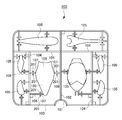
- FIG. 3 is a top view which shows an example of the resin molding component for models used with a model component separation jig same as the above.
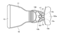
- (a) is the state in the middle of setting a model component separation jig,
- (b) has shown the state which set the model component separation jig.
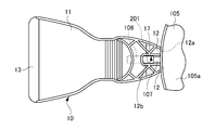
- FIG. 9 It is a top view of a model component separation jig same as the above shown in the state set to the resin molded component for models shown in FIG.5 and FIG.6. It is a side view of a model components separation jig same as the above shown in the state of FIG. It is the top view which shows the resin molded component for models of this invention. It is explanatory drawing when using a model component separation jig same as the above in the resin molded part for models shown in FIG. 9, (a) is the state in the middle of setting a model component separation jig, (b) is a model component separation jig. The state where is set is shown.
- a model component assembly plate 100 as a model resin molded component includes a semicircular main runner 101 into which a molten resin material first flows from an injection molding machine, a sub runner 102 and an outer periphery runner 103 following the main runner 101.
- the branch runner 104 branched from the sub-runner 102 or the outer periphery runner 103, the model component 105, and the connection member 106 connecting each branch runner 104 and the model component 105 are integrally formed, so that a plate shape is obtained. It is formed as a model part assembly plate.
- the outer diameter is smaller (thinner) than the other part of the connection member 106.
- a holding unit 107 is provided. When the model component assembly plate 100 pushes the model component 105 up and down with respect to the connection member 106, the portion of the holding portion 107 is broken, and the model component 105 can be separated from the connection member 106 by this breakage. It can be done.
- the model component assembly plate 100 having this type of structure is a model component assembly plate that has been well known.
- FIGS. 1 to 4 show a model component separating jig according to the present invention
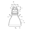
- FIG. 1 is a perspective view thereof
- FIG. 2 is a plan view thereof viewed from the upper surface side
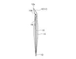
- FIG. 3 is a sectional view taken along line AA in FIG. 4 is a cross-sectional view taken along line BB in FIG.
- a model component separating jig 10 is formed of a resinous material, and a jig body 11 and left and right 1 extending in parallel from one end of the jig body 11 toward the outside.
- the pair of claw portions 12 and 12 and a correction spatula portion 13 extending outward from the other end of the jig main body portion 11 are integrally provided.
- the pair of claw portions 12, 12 is provided with a slit groove 17 having a width slightly larger than the outer diameter width of the connection member 106, and from one end of the jig body portion 11. It extends in parallel toward the outside and is formed in a fork shape. Further, as shown in FIGS. 1 and 3, each claw portion 12, 12 gradually decreases in thickness from the base portion 12 b, which is the back end of the slit groove 17, toward the claw tip portion 12 a. It is formed to be slightly inclined obliquely upward toward the portion 12a.
- the length L (see FIG. 2) from the base portion 12b of the claw portions 12 and 12 to the claw tip portion 12a (see FIG. 2) is such that the connecting member 106 is inserted into the slit groove 17 as shown in FIG. Then, the jig body 11 faces the model component assembly plate 100, and the jig body 11 is moved to the left and right from the surface (upper surface) 105a side to the other surface (lower surface) 105b side of the model component 105. When the claw portions 12 and 12 are inserted, the claw tip portions 12 a and 12 a can be latched and engaged with a part of the other surface 105 of the model part 105 as shown in FIGS. 6B, 7, and 8. The length is set.
- the correction spatula portion 13 is formed in a wedge shape in cross section so that the thickness gradually decreases from the other end of the jig main body portion 11 toward the tip end side.
- the correction spatula 13 was mistaken by inserting the correction spatula 13 into the gap between the assembled model parts when it was noticed that the model part 105 was assembled incorrectly during assembly work. Can be used to remove or modify parts.
- the reinforcing side wall 14 is integrally formed.
- the reinforcing side walls 14 project at right angles to the upper and lower surfaces of the model component separating jig 10, and therefore the cross section of the jig main body 11 and the reinforcing side wall 14, and the claw 12 and the reinforcing side wall 14.
- Each of the cross sections is formed as a cross section having a substantially T-shape as shown in FIGS.
- the reinforcing side wall 14 has a function of improving the strength of the model component separating jig 10 in the vertical rotation direction.
- the jig main body part 11 has the left and right side portions 11a, 11a of the jig main body part 11 recessed inwardly and the other end side of the jig main body part 11 is expanded in the left-right direction.
- a grip 15 is provided to facilitate gripping the model component separating jig 10 by hand.
- reinforcing ribs 16 are integrally formed in a lattice shape on the surface (upper surface) side of the jig main body 11 and the claw portions 12 and 12.
- the reinforcing rib 16 has a function of improving the strength of the model component separating jig 10 in the vertical rotation direction, like the reinforcing side wall 14.
- the reinforcing ribs 16 may be provided on the back surface (lower surface) side or on both the front and back surfaces.
- the slit groove 17 is made to correspond to the connecting member 106 holding the model part 105 to be separated and removed, and the model part separating jig 10 is moved from the upper side of the model part 105 to the model part. It faces the assembly board 100. Further, the model component separating jig 10 is inserted toward the model component assembly plate 200, and the claw tip portions 12a and 12a of the claw portions 12 and 12 are inserted into the claw portions 12 and 12, as shown in FIGS. The model component 105 is hooked on the other surface 105b side.
- the jig main body 11 is attached to the position of the jig main body 11 that is in contact with the connecting member 106 (in this embodiment, the back surface of the base 12b). It rotates with the nail
- This push-up force acts as a large force between the connection member 106 and the model component 105 due to the lever action, and the model component 105 breaks from the holding portion 107 of the connection member 106 and is easily separated.
- the connection member 106 can be connected even if the model component separation jig 10 is rotated with a small force. A large pushing force is applied between the holding portion 107 and the model component 105, and the model component 105 can be easily separated from the connection member 106. As a result, the work can be performed without feeling finger fatigue. In addition, since it is formed of a resinous material, it is possible to reduce the size and weight, and the cost can be reduced and provided at a low cost.
- FIG. 9 shows an embodiment of the model component assembly plate according to the present invention suitable for easily separating the model component 105 from the connecting member 106 using the model component separation jig 10 according to the present invention. is there.
- the model component assembly plate 200 in this embodiment is extended from the connection member 106 to the outside at a substantially right angle on the left and right side surfaces of the connection member 106 corresponding to the back surface of the jig body 11.
- the branch portions 201 and 201 are formed integrally with the connection member 106, and the other configurations are the same as those of the model component assembly plate 100 shown in FIGS.
- the slit groove 17 is made to correspond to the connecting member 106 holding the model part 105 to be removed, and the model part separation jig 10 is attached to the model part assembly plate 200 from the upper side of the model part 105.
- the model component separating jig 10 is inserted toward the model component assembly plate 200, and the claw tip portions 12a and 12a of the claw portions 12 and 12 are inserted as shown in FIGS.
- the model component 105 is hooked on the other surface 105b side.
- the jig body 11 rotates together with the claws 12 and 12, using the position of the jig body 11 in contact with the left and right branches 201 and 201 as a fulcrum.
- the claws of the claws 12 and 12 The tip portions 12a and 12a push the other surface 105b of the model part 105 up to the one surface 105a side.
- This push-up force also acts as a large force between the connection member 106 and the model component 105 due to the lever action, and the model component 105 breaks from the holding portion 107 of the connection member 106 and is easily separated.
- the branch portions 201 and 201 are integrally formed on the left and right side surfaces of the connection member 106 corresponding to the back surfaces of the claw portions 12 and 12,
- the claw portions 12, 12 can contact the lower surface of the model part 105 on both the left and right sides of the connection member 106.
- the wobbling on the left and right at 10 is eliminated, and the push-up force is accurately applied in the upward direction, so that breakage is easily performed.
- the branch portions 201 and 201 are provided on the left and right sides of the connection member 106, but a structure in which the branch portions 201 and 201 are provided on either of the left and right sides may be employed.
- model component separating jig and the model component assembly plate according to the present invention are not limited to the above-described embodiments, and are described in the claims of the utility model registration. Various modifications and changes can be made within the scope of the present invention.
- Model Parts Separating Jig 11 Jig Main Body 11a Left and Right Side Parts 12 Claw 12a Claw Tip 13 Spatula 14 Reinforcing Side Wall 15 Grip 16 Rib 17 Slit Groove L Claw Length 100 Model Parts Assembly Plate ( Resin molded parts for models) DESCRIPTION OF SYMBOLS 101 Main runner 102 Sub runner 103 Outer periphery runner 104 Branch runner 105 Model component 105a Surface 105b Other surface 106 Connection member 107 Holding part 200 Model component assembly board (resin molded part for model) 201 Branch
Landscapes
- Life Sciences & Earth Sciences (AREA)
- Forests & Forestry (AREA)
- Engineering & Computer Science (AREA)
- Mechanical Engineering (AREA)
- Moulds For Moulding Plastics Or The Like (AREA)
- Toys (AREA)
- Perforating, Stamping-Out Or Severing By Means Other Than Cutting (AREA)
- Knives (AREA)
Abstract
【課題】指を疲れさせることなく模型部品をランナーから簡単に分離することができる模型部品分離治具を提供する。 【解決手段】ランナーと、模型部品105と、該ランナーと該模型部品105を接続している接続部材106を一体に成形した模型用樹脂成形部品から模型部品105を分離する模型部品分離治具であって、治具本体部11と、接続部材105の外径幅より大きな幅を有して治具本体部11の一端から外側に向かって平行に延設された1対の爪部12,12とを有するとともに、該1対の爪部12,12の長さを該1対の爪部12,12が接続部材106を挟んで模型部品105の表面105a側から他面105b側に挿入された際に該爪部12,12の爪先端部12a,12aが模型部品105の他面105b側に掛け止め係合できる長さにしてなる模型部品分離治具。
Description
本発明は、模型部品分離治具及び模型用樹脂成形部品に関するものである。
従来、プラスチックを材料にした模型部品を組み立てることで、自動車やロボット等の玩具を完成させるプラスチックモデル(以下、「プラモデル」(登録商標)という)が知られている(例えば、特許文献1参照)。
一般に、このプラモデルの模型部品は、模型部品と、枠部材(以下、「ランナー」という)と、該枠部材と該模型部品を接続している接続部材とを一体にして、板状の模型用樹脂成形部品(以下、「模型部品アッセンブリ板」という)として成形し、これが1枚または複数枚にまとめられてユーザに提供される。
一方、ユーザ側では、プラモデルに付属の組立説明書の記載に従い、必要とする模型部品を、接続部材の部分において指で折り曲げて切り離し、あるいは、ニッパ等の工具を用いて模型部品アッセンブリ板から切り取って組立を行っている。また、プラモデルも複雑なものになると、多数個の模型部品を用いることが一般的であり、したがって模型部品を接続部材の部分で切り離すには、プラモデルを完成させる迄に相当回数の切り離し作業が必要になる。
しかしながら、多数の模型部品を使用して完成させるプラモデルの場合、模型部品を指で摘んで接続部材の部分で切り離すには、手間がかかり、また、指も疲れるという問題点があった。一方、ニッパ等の工具を所有していない場合には新たに購入しなければならず、またニッパ等の工具の使用はユーザの年齢によっては危険な面があるという問題点があった。
そこで、本発明は、上記問題点に鑑みなされたものであって、その目的は指を疲れさせることなく模型部品をランナーから簡単に分離することができるコンパクトな模型部品分離治具を提供するものである。さらに、他の目的は、模型部品分離治具を使用して模型部品をランナーからより一層簡単に分離することができるようにする模型用樹脂成形部品を提供するものである。
前記課題を解決するために、本発明である模型部品分離治具は、模型部品と、ランナーと、該ランナーと該模型部品を接続している接続部材を一体に成形した模型用樹脂成形部品から前記模型部品を分離する模型部品分離治具であって、治具本体部と、前記接続部材の外径幅より大きな幅を有して該治具本体部の一端から外側に向かって平行に延設された1対の爪部とを有するとともに、該1対の爪部の長さを該1対の爪部が前記接続部材を挟んで前記模型部品の表面側から他面側に挿入された際に該爪部の爪先端部が前記模型部品の他面側に掛け止め係合できる長さに形成してなることを特徴とする。
この構成によれば、接続部材を爪部の間に挿入するようにして、1対の爪部を模型部品の一面側から他面側に向かって差し込み、この爪部の爪先端部を模型部品の他面側に掛け止めし、その後、治具本体部の他端を押し下げると、治具本体部と接続部材が互いに当接した部分を支点にして、治具本体部が爪部と共に回転し、このとき爪部が模型部品の他面を一面側に押し上げる。この押し上げ力は、てこの作用により接続部材と模型部品との間に大きな力となって働き、この大きな押し上げ力により模型部品が接続部材から容易に切り離される。すなわち、模型部品分離治具を小さな力で回動操作しても、接続部材と模型部品との間に大きな力が加わり、模型部品を接続部材から容易に切り離すことができる。また、コンパクトな模型部品分離治具として構成することができる。
上記構成において、前記治具本体部の他端部に、該他端部から外側に向かって延設された断面楔状の修正用ヘラ部が形成されている、構成を採用できる。
この構成によれば、組立作業の途中で、模型部品を間違えて組み付けたことに気が付いたようなときに、修正用ヘラ部を使用して間違えた部品を取り外したりすることができる。
上記構成において、前記治具本体部と前記爪部の外周側部に、該治具本体部と該爪部の外周側部から上下方向へ直角に延びる補強用側壁が一体に形成されている、構成を採用できる。
この構成によれば、補強用側壁を設けることにより、分離治具の上下回転方向における強度が向上する。したがって、切り離しを小さな力で行うことができる模型用樹脂成形部品から大きな力を必要とする模型用樹脂成形部品に至るまで、同じ模型部品分離治具を使用できる。
上記構成において、前記治具本体部と前記爪部の表裏面の少なくとも一方の面には、リブが格子状に形成されている、構成を採用できる。
この構成によれば、格子状のリブを設けることにより、分離治具の上下回転方向における強度がさらに向上する。したがって、切り離しを小さな力で行うことができる模型用樹脂成形部品からさらに大きな力を必要とする模型用樹脂成形部品に至るまで、同じ模型部品分離治具を使用できる。
上記構成において、前記治具本体部には、グリップが形成されている、構成を採用できる。
この構成によれば、手でグリップを掴んで分離治具を簡単に扱い、模型用樹脂成形部品から模型部品を容易に切り離すことができる。
また、本発明である模型用樹脂成形部品は、模型部品と、ランナーと、該ランナーと該模型部品を接続している接続部材を一体に成形してなる模型用樹脂成形部品において、前記接続部材に、該接続部材とほぼ直角に交差している枝部を設けてなることを特徴とする。
この構成による模型用樹脂成形部品は、本発明の模型部品分離治具を使用して、模型部品を接続部材から容易に切り離すのにより適した構造にしたものである。すなわち、接続部材を模型部品分離治具の爪部の間に挿入するようにして、1対の爪部を模型部品の一面側から他面側に向かって差し込み、この爪部の爪先端部を模型部品の他面側に掛け止めし、その後、治具本体部の他端を押し下げると、治具本体と枝部が互いに当接する。その後、治具本体部の他端を押し下げると、この枝部と治具本体部が互いに当接している部分を支点にして、治具本体部が爪部と共に回転し、このとき爪部が模型部品の他面を一面側に押し上げる。この押し上げ力は、てこの作用により接続部材と模型部品との間に大きな力となって働き、この大きな押し上げ力により模型部品が接続部材から容易に切り離される。
本発明の模型部品分離治具によれば、指に大きな力を加えなくても、この模型部品分離治具を用いて模型部品を接続部材から容易に切り離すことができる。したがって、指の疲れを低減できる。
一方、本発明の模型用樹脂成形部品によれば、本発明の模型部品分離治具を使用して、模型部品を接続部材から容易に切り離すことができる。
以下、図面を参照して本発明について詳細に説明する。
(本発明の模型部品分離治具を使用可能な模型用樹脂成形部品の一例)
まず、本発明の模型部品分離治具で使用する模型部品アッセンブリ板100の一例について図5を使用して説明する。同図において、模型用樹脂成形部品としての模型部品アッセンブリ板100は、溶融樹脂材料が射出成型機から最初に流入する半円形のメインランナー101と、これに続くサブランナー102及び外周ランナー103と、サブランナー102または外周ランナー103からそれぞれ分岐する枝ランナー104と、模型部品105と、各枝ランナー104と模型部品105を接続している接続部材106と、が一体成形されることで、板状をした模型部品アッセンブリ板として形成されている。
まず、本発明の模型部品分離治具で使用する模型部品アッセンブリ板100の一例について図5を使用して説明する。同図において、模型用樹脂成形部品としての模型部品アッセンブリ板100は、溶融樹脂材料が射出成型機から最初に流入する半円形のメインランナー101と、これに続くサブランナー102及び外周ランナー103と、サブランナー102または外周ランナー103からそれぞれ分岐する枝ランナー104と、模型部品105と、各枝ランナー104と模型部品105を接続している接続部材106と、が一体成形されることで、板状をした模型部品アッセンブリ板として形成されている。
また、接続部材106と模型部品105との間には、模型部品105を接続部材106から切り離しやすくするために、接続部材106の他の部分よりも小さな外径にして(細く)形成されている保持部107が設けられている。そして、この模型部品アッセンブリ板100は、模型部品105を接続部材106に対して上下方向に押し上げると、保持部107の箇所が折損し、この折損により模型部品105を接続部材106から分離することができるようになっている。なお、この種の構造をした模型部品アッセンブリ板100は、従来から良く知られた模型部品アッセンブリ板である。
(本発明に係る模型部品分離治具の一実施例)
次に、本発明に係る模型部品分離治具の一実施例について図1~図4を使用して説明する。図1~図4は本発明に係る模型部品分離治具を示し、図1はその斜視図、図2は上面側より見たその平面図、図3は図2のA-A線断面図、図4は図2のB-B線断面図である。また、以下の説明において、図2の上下方向上側を模型部品分離治具の一端側、下側を他端側とし、さらに左右方向を模型部品分離治具の左右、紙面に垂直な方向を模型部品分離治具の上下としてそれぞれ説明する。なお、各実施例における説明の全体を通して、同じ要素には同じ番号を付している。
次に、本発明に係る模型部品分離治具の一実施例について図1~図4を使用して説明する。図1~図4は本発明に係る模型部品分離治具を示し、図1はその斜視図、図2は上面側より見たその平面図、図3は図2のA-A線断面図、図4は図2のB-B線断面図である。また、以下の説明において、図2の上下方向上側を模型部品分離治具の一端側、下側を他端側とし、さらに左右方向を模型部品分離治具の左右、紙面に垂直な方向を模型部品分離治具の上下としてそれぞれ説明する。なお、各実施例における説明の全体を通して、同じ要素には同じ番号を付している。
同図において、模型部品分離治具10は、樹脂性材料により形成されており、治具本体部11と、該治具本体部11の一端から外側に向かって平行に延設されている左右1対の爪部12,12と、該治具本体部11の他端から外側に向かって延設されている修正用ヘラ部13とを一体に有している。
前記1対の爪部12,12は、図2に示すように、間に前記接続部材106の外径幅より若干大きな幅を有するスリット溝17を設けて、前記治具本体部11の一端から外側に向かって平行に延設されてフォーク状に形成されている。また、各爪部12,12は、図1及び図3に示すように、スリット溝17の奥側端である基部12bから爪先端部12aに向かって厚みが徐々に薄くなり、また、爪先端部12aに向かって斜め上方に若干傾斜して形成されている。
なお、前記爪部12,12の基部12bから爪先端部12aまでの長さL(図2参照)は、図6(a)に示すように、スリット溝17内に前記接続部材106を差し込むようにして、治具本体部11を模型部品アッセンブリ板100に臨ませ、さらに該治具本体部11を前記模型部品105の表面(上面)105a側から他面(下面)105b側に向かって左右の爪部12,12を挿入した際、図6(b),図7,図8に示すように、各爪先端部12a,12aが模型部品105の他面105の一部に掛け止め係合できる長さに設定してある。
前記修正用ヘラ部13は、治具本体部11の他端から先端側に向かって徐々に肉厚が薄くなるようにして、断面楔状に形成されている。この修正用ヘラ部13は、組立作業の途中に、模型部品105を間違えて組み付けたことに気が付いたようなときに、この修正用ヘラ部13を組み付けた模型部品の隙間に差し込むことで間違えた部品を取り外したり、あるいは修正したりするのに使用できる。
また、模型部品分離治具10の爪部12の全周及び治具本体部11の左右両側には、これら爪部12の全周及び治具本体部11の左右両側を連続した状態で囲むようにして、補強用側壁14が一体に形成されている。この補強用側壁14は、模型部品分離治具10の上下面側にそれぞれ直角に突出しており、したがって治具本体部11と補強用側壁14との断面及び爪部12と補強用側壁14との断面は、図3及び図4に示すようにそれぞれ概略T字状をした断面として形成されている。なお、この補強用側壁14は、模型部品分離治具10の上下回転方向における強度を向上させる機能を有する。
また、治具本体部11には、該治具本体部11の左右側面における一部11a,11aをそれぞれ内側に向けて凹ませるとともに該治具本体部11の他端側を左右方向に膨らませて、手で模型部品分離治具10を掴みやすくするためのグリップ15が設けられている。
さらに、前記治具本体部11と前記爪部12,12の表面(上面)側には、補強用のリブ16が格子形状にして一体に形成されている。この補強用リブ16は、前記補強用側壁14と同様に、前記模型部品分離治具10の上下回転方向における強度を向上させる機能を有する。なお、この補強用リブ16は、裏面(下面)側に設けても、あるいは表裏両面に設けてもよい。
次に、このように構成された模型部品分離治具10を使用して、図5に示した模型部品アッセンブリ板100から模型部品105を分離する動作を、図6乃至図8を使用して説明する。まず、図6(a)に示すように分離して取り外す模型部品105を保持している接続部材106にスリット溝17を対応させて、模型部品分離治具10を模型部品105の上側から模型部品アッセンブリ板100に臨ませる。また、さらに模型部品分離治具10を模型部品アッセンブリ板200に向けて差し込み、図6(b)及び図7,図8に示すように、爪部12,12の各爪先端部12a,12aを模型部品105の他面105b側に掛け止めする。
次いで、治具本体部11の他端を押し下げると、接続部材106と当接している治具本体部11の箇所(本実施例では基部12bの裏面)を支点にして、治具本体部11が爪部12,12と共に回転し、このとき爪部12,12の爪先端部12a,12aが模型部品105の他面105bを一面105a側に押し上げる。この押し上げ力は、てこの作用により接続部材106と模型部品105との間に大きな力となって働き、模型部品105が接続部材106の保持部107から折損して容易に分離される。
したがって、本発明の実施例に係る模型部品分離治具10を使用して模型部品105の分離作業を行うと、模型部品分離治具10を小さな力で回動操作しても、接続部材106の保持部107と模型部品105との間に大きな押し上げ力が加わり、模型部品105を接続部材106から容易に切り離すことができる。これにより、指の疲れを感じさせることなく作業を行うことができる。また、樹脂性材料により形成しているので、小型軽量化が可能になり、さらにコストも小さく、安価に提供することができる。
(本発明に係る模型用樹脂成形部品の一実施例)
図9は、本発明に係る模型部品分離治具10を使用して、接続部材106から模型部品105を容易に切り離すのに適した本発明に係る模型部品アッセンブリ板の一実施例を示すものである。同図において、本実施例における模型部品アッセンブリ板200は、治具本体部11の裏面と対応している接続部材106の左右側面に、それぞれ該接続部材106から外側へ向かってほぼ直角に延設している枝部201,201を接続部材106と一体に形成して設けたもので、他の構成は図5~図8に示した模型部品アッセンブリ板100と同じである。
図9は、本発明に係る模型部品分離治具10を使用して、接続部材106から模型部品105を容易に切り離すのに適した本発明に係る模型部品アッセンブリ板の一実施例を示すものである。同図において、本実施例における模型部品アッセンブリ板200は、治具本体部11の裏面と対応している接続部材106の左右側面に、それぞれ該接続部材106から外側へ向かってほぼ直角に延設している枝部201,201を接続部材106と一体に形成して設けたもので、他の構成は図5~図8に示した模型部品アッセンブリ板100と同じである。
次に、前記模型部品分離治具10を使用して、この模型部品アッセンブリ板200から模型部品105を分離する動作を、図10乃至図12を使用して説明する。まず、図10(a)に示すように取り外す模型部品105を保持している接続部材106にスリット溝17を対応させて、模型部品105の上側から模型部品分離治具10を模型部品アッセンブリ板200に臨ませる。また、さらに模型部品分離治具10を模型部品アッセンブリ板200に向けて差し込み、図10(b)及び図11,図12に示すように、爪部12,12の各爪先端部12a,12aを模型部品105の他面105b側に掛け止めする。
次いで、治具本体部11の他端を押し下げると、爪部12,12の裏面が接続部材106及びこの接続部材106に形成されている左右の枝部201,201とそれぞれ当接し、この接続部材106及び左右の枝部201,201と接触している治具本体部11の箇所を支点にして、治具本体部11が爪部12,12と共に回転し、このとき爪部12,12の爪先端部12a,12aが模型部品105の他面105bを一面105a側に押し上げる。この押し上げ力も、てこの作用により接続部材106と模型部品105との間に大きな力となって働き、模型部品105が接続部材106の保持部107から折損して容易に分離される。
したがって、本発明の実施例に係る模型部品アッセンブリ板200のように、爪部12,12の裏面と対応し、接続部材106の左右側面に枝部201,201を一体に形成したものでは、模型部品分離治具10を使用して模型部品105を分離させるとき、爪部12,12が接続部材106の左右両側でそれぞれ模型部品105の下面に当接することができるので、この模型部品分離治具10における左右のぐらつきが無くなり、また、押し上げ力が上方向に向かって正確に付与されて、折損が容易に行われることになる。
なお、本実施例における模型部品アッセンブリ板200では、接続部材106の左右両側に枝部201,201を設けているが、左右いずれか一方に枝部201,201を設けた構造にしてもよい。
以上、本発明の好ましい実施例について詳述したが、本発明に係る模型部品分離治具及び模型部品アッセンブリ板は上述した実施例に限定されるものではなく、実用新案登録請求の範囲に記載された本発明の要旨の範囲内において、種々の変形、変化が可能である。
10 模型部品分離治具
11 治具本体部
11a 左右側面の一部
12 爪部
12a 爪先端部
13 ヘラ部
14 補強用側壁
15 グリップ
16 リブ
17 スリット溝
L 爪部の長さ
100 模型部品アッセンブリ板(模型用樹脂成形部品)
101 メインランナー
102 サブランナー
103 外周ランナー
104 枝ランナー
105 模型部品
105a 表面
105b 他面
106 接続部材
107 保持部
200 模型部品アッセンブリ板(模型用樹脂成形部品)
201 枝部
11 治具本体部
11a 左右側面の一部
12 爪部
12a 爪先端部
13 ヘラ部
14 補強用側壁
15 グリップ
16 リブ
17 スリット溝
L 爪部の長さ
100 模型部品アッセンブリ板(模型用樹脂成形部品)
101 メインランナー
102 サブランナー
103 外周ランナー
104 枝ランナー
105 模型部品
105a 表面
105b 他面
106 接続部材
107 保持部
200 模型部品アッセンブリ板(模型用樹脂成形部品)
201 枝部
Claims (6)
- 枠部材と、模型部品と、該枠部材と該模型部品を接続している接続部材を一体に成形した模型用樹脂成形部品から前記模型部品を分離する模型部品分離治具であって、
治具本体部と、
前記接続部材の外径幅より大きな幅を有して該治具本体部の一端から外側に向かって平行に延設された1対の爪部と、を有し、
該1対の爪部の長さを該1対の爪部が互いに前記接続部材を挟んで前記模型部品の表面側から他面側に挿入された際に該爪部の爪先端部が前記模型部品の他面側に掛け止め係合できる長さにしてなることを特徴とする模型部品分離治具。 - 前記治具本体部の他端部に、該他端部から外側に向かって延設された断面楔状の修正用ヘラ部が形成されていることを特徴とする請求項1に記載の模型部品分離治具。
- 前記治具本体部と前記爪部の外周側部に、該治具本体部と該爪部の外周側部から上下方向へ直角に延びる補強用側壁が一体に形成されていることを特徴とする請求項1または請求項2に記載の模型部品分離治具。
- 前記治具本体部と前記爪部の表裏面の少なくとも一方の面には、リブが格子状に形成されていることを特徴とする請求項1乃至3に記載の模型部品分離治具。
- 前記治具本体部には、グリップが形成されていることを特徴とする請求項1乃至4に記載の模型部品分離治具。
- 枠部材と、模型部品と、該枠部材と該模型部品を接続している接続部材を一体に成形してなる模型用樹脂成形部品において、
前記接続部材に、該接続部材とほぼ直角に交差している枝部を設けてなることを特徴とする模型用樹脂成形部品。
Priority Applications (1)
| Application Number | Priority Date | Filing Date | Title |
|---|---|---|---|
| CN201090001106.9U CN202781222U (zh) | 2009-11-04 | 2010-06-03 | 模型零件分离夹具及模型用树脂成形零件 |
Applications Claiming Priority (2)
| Application Number | Priority Date | Filing Date | Title |
|---|---|---|---|
| JP2009-007850U | 2009-11-04 | ||
| JP2009007850U JP3157588U (ja) | 2009-11-04 | 2009-11-04 | 模型部品分離治具及び模型用樹脂成形部品 |
Publications (1)
| Publication Number | Publication Date |
|---|---|
| WO2011055563A1 true WO2011055563A1 (ja) | 2011-05-12 |
Family
ID=43969803
Family Applications (1)
| Application Number | Title | Priority Date | Filing Date |
|---|---|---|---|
| PCT/JP2010/059452 Ceased WO2011055563A1 (ja) | 2009-11-04 | 2010-06-03 | 模型部品分離治具及び模型用樹脂成形部品 |
Country Status (3)
| Country | Link |
|---|---|
| JP (1) | JP3157588U (ja) |
| CN (1) | CN202781222U (ja) |
| WO (1) | WO2011055563A1 (ja) |
Families Citing this family (4)
| Publication number | Priority date | Publication date | Assignee | Title |
|---|---|---|---|---|
| JP5358555B2 (ja) * | 2010-12-21 | 2013-12-04 | 株式会社バンダイ | シール貼付治具 |
| JP5301595B2 (ja) * | 2011-03-11 | 2013-09-25 | 株式会社バンダイ | パーツ供給品 |
| JP6623065B2 (ja) * | 2015-12-28 | 2019-12-18 | 株式会社アーテック | 被覆剥がし具、及びパーツセット |
| JP7836571B2 (ja) * | 2022-07-25 | 2026-03-27 | ヨシリツ株式会社 | 組立ブロックのパーツリムーバー |
Citations (2)
| Publication number | Priority date | Publication date | Assignee | Title |
|---|---|---|---|---|
| JPH0468765U (ja) * | 1990-10-19 | 1992-06-18 | ||
| JP2004001458A (ja) * | 2002-04-04 | 2004-01-08 | Epock Kyoei Co Ltd | 物品を内蔵した透明樹脂成型体の製造方法 |
-
2009
- 2009-11-04 JP JP2009007850U patent/JP3157588U/ja not_active Expired - Lifetime
-
2010
- 2010-06-03 WO PCT/JP2010/059452 patent/WO2011055563A1/ja not_active Ceased
- 2010-06-03 CN CN201090001106.9U patent/CN202781222U/zh not_active Expired - Lifetime
Patent Citations (2)
| Publication number | Priority date | Publication date | Assignee | Title |
|---|---|---|---|---|
| JPH0468765U (ja) * | 1990-10-19 | 1992-06-18 | ||
| JP2004001458A (ja) * | 2002-04-04 | 2004-01-08 | Epock Kyoei Co Ltd | 物品を内蔵した透明樹脂成型体の製造方法 |
Also Published As
| Publication number | Publication date |
|---|---|
| JP3157588U (ja) | 2010-02-25 |
| CN202781222U (zh) | 2013-03-13 |
Similar Documents
| Publication | Publication Date | Title |
|---|---|---|
| JP3157588U (ja) | 模型部品分離治具及び模型用樹脂成形部品 | |
| CN103477256B (zh) | 光纤用被覆层去除工具以及被覆层去除方法 | |
| JP2003291072A (ja) | プライヤ | |
| CN111655588A (zh) | 紧固件 | |
| TW537951B (en) | Self-securing tool handle | |
| CN107002730B (zh) | 防止注塑成型部件分离的紧固装置 | |
| KR20170061936A (ko) | 사출품 조립 구조 | |
| TWI619584B (zh) | Tool with pivoting function | |
| CN111957055B (zh) | 魔术盖组合玩具造型拆装工具 | |
| JPH09304159A (ja) | 組立式計量スプーン | |
| JP3952656B2 (ja) | モールド締結構造 | |
| JP5578732B2 (ja) | 圧着工具 | |
| JP2002307333A (ja) | 分別廃棄用手動利器 | |
| JP2003237269A (ja) | クリップ | |
| JP2002119776A (ja) | 手動利器における柄部の緩衝構造 | |
| JP3137886U (ja) | 刃物のグリップ | |
| KR101131269B1 (ko) | 자동차의 내장재 결합 구조 | |
| JP3098294U (ja) | コーキングガン | |
| JP2002187089A (ja) | 掴み装置 | |
| JPH08315712A (ja) | ヒューズプラー | |
| JP3222669U (ja) | ペンチ | |
| JPH10173368A (ja) | スナップフィット係合構造 | |
| JP2011255487A (ja) | ドライバー回転アシストアダプター、及びそれに用いる装着補助具 | |
| KR20090102137A (ko) | 니퍼날체 및 이를 이용한 니퍼 | |
| JP3171892U (ja) | うちわの握り補助具 |
Legal Events
| Date | Code | Title | Description |
|---|---|---|---|
| WWE | Wipo information: entry into national phase |
Ref document number: 201090001106.9 Country of ref document: CN |
|
| 121 | Ep: the epo has been informed by wipo that ep was designated in this application |
Ref document number: 10828124 Country of ref document: EP Kind code of ref document: A1 |
|
| NENP | Non-entry into the national phase |
Ref country code: DE |
|
| 122 | Ep: pct application non-entry in european phase |
Ref document number: 10828124 Country of ref document: EP Kind code of ref document: A1 |