WO2011049153A1 - リチウム二次電池およびリチウム二次電池用集電箔の製造方法、ならびにリチウム二次電池用集電箔 - Google Patents
リチウム二次電池およびリチウム二次電池用集電箔の製造方法、ならびにリチウム二次電池用集電箔 Download PDFInfo
- Publication number
- WO2011049153A1 WO2011049153A1 PCT/JP2010/068544 JP2010068544W WO2011049153A1 WO 2011049153 A1 WO2011049153 A1 WO 2011049153A1 JP 2010068544 W JP2010068544 W JP 2010068544W WO 2011049153 A1 WO2011049153 A1 WO 2011049153A1
- Authority
- WO
- WIPO (PCT)
- Prior art keywords
- current collector
- foil
- lithium secondary
- secondary battery
- collector foil
- Prior art date
Links
Images


Classifications
-
- H—ELECTRICITY
- H01—ELECTRIC ELEMENTS
- H01M—PROCESSES OR MEANS, e.g. BATTERIES, FOR THE DIRECT CONVERSION OF CHEMICAL ENERGY INTO ELECTRICAL ENERGY
- H01M4/00—Electrodes
- H01M4/02—Electrodes composed of, or comprising, active material
- H01M4/13—Electrodes for accumulators with non-aqueous electrolyte, e.g. for lithium-accumulators; Processes of manufacture thereof
- H01M4/139—Processes of manufacture
-
- H—ELECTRICITY
- H01—ELECTRIC ELEMENTS
- H01M—PROCESSES OR MEANS, e.g. BATTERIES, FOR THE DIRECT CONVERSION OF CHEMICAL ENERGY INTO ELECTRICAL ENERGY
- H01M10/00—Secondary cells; Manufacture thereof
- H01M10/05—Accumulators with non-aqueous electrolyte
- H01M10/058—Construction or manufacture
-
- H—ELECTRICITY
- H01—ELECTRIC ELEMENTS
- H01M—PROCESSES OR MEANS, e.g. BATTERIES, FOR THE DIRECT CONVERSION OF CHEMICAL ENERGY INTO ELECTRICAL ENERGY
- H01M10/00—Secondary cells; Manufacture thereof
- H01M10/04—Construction or manufacture in general
- H01M10/0431—Cells with wound or folded electrodes
-
- H—ELECTRICITY
- H01—ELECTRIC ELEMENTS
- H01M—PROCESSES OR MEANS, e.g. BATTERIES, FOR THE DIRECT CONVERSION OF CHEMICAL ENERGY INTO ELECTRICAL ENERGY
- H01M10/00—Secondary cells; Manufacture thereof
- H01M10/05—Accumulators with non-aqueous electrolyte
- H01M10/052—Li-accumulators
-
- H—ELECTRICITY
- H01—ELECTRIC ELEMENTS
- H01M—PROCESSES OR MEANS, e.g. BATTERIES, FOR THE DIRECT CONVERSION OF CHEMICAL ENERGY INTO ELECTRICAL ENERGY
- H01M10/00—Secondary cells; Manufacture thereof
- H01M10/05—Accumulators with non-aqueous electrolyte
- H01M10/052—Li-accumulators
- H01M10/0525—Rocking-chair batteries, i.e. batteries with lithium insertion or intercalation in both electrodes; Lithium-ion batteries
-
- H—ELECTRICITY
- H01—ELECTRIC ELEMENTS
- H01M—PROCESSES OR MEANS, e.g. BATTERIES, FOR THE DIRECT CONVERSION OF CHEMICAL ENERGY INTO ELECTRICAL ENERGY
- H01M10/00—Secondary cells; Manufacture thereof
- H01M10/05—Accumulators with non-aqueous electrolyte
- H01M10/056—Accumulators with non-aqueous electrolyte characterised by the materials used as electrolytes, e.g. mixed inorganic/organic electrolytes
- H01M10/0564—Accumulators with non-aqueous electrolyte characterised by the materials used as electrolytes, e.g. mixed inorganic/organic electrolytes the electrolyte being constituted of organic materials only
- H01M10/0566—Liquid materials
-
- H—ELECTRICITY
- H01—ELECTRIC ELEMENTS
- H01M—PROCESSES OR MEANS, e.g. BATTERIES, FOR THE DIRECT CONVERSION OF CHEMICAL ENERGY INTO ELECTRICAL ENERGY
- H01M10/00—Secondary cells; Manufacture thereof
- H01M10/05—Accumulators with non-aqueous electrolyte
- H01M10/058—Construction or manufacture
- H01M10/0585—Construction or manufacture of accumulators having only flat construction elements, i.e. flat positive electrodes, flat negative electrodes and flat separators
-
- H—ELECTRICITY
- H01—ELECTRIC ELEMENTS
- H01M—PROCESSES OR MEANS, e.g. BATTERIES, FOR THE DIRECT CONVERSION OF CHEMICAL ENERGY INTO ELECTRICAL ENERGY
- H01M10/00—Secondary cells; Manufacture thereof
- H01M10/05—Accumulators with non-aqueous electrolyte
- H01M10/058—Construction or manufacture
- H01M10/0587—Construction or manufacture of accumulators having only wound construction elements, i.e. wound positive electrodes, wound negative electrodes and wound separators
-
- H—ELECTRICITY
- H01—ELECTRIC ELEMENTS
- H01M—PROCESSES OR MEANS, e.g. BATTERIES, FOR THE DIRECT CONVERSION OF CHEMICAL ENERGY INTO ELECTRICAL ENERGY
- H01M4/00—Electrodes
- H01M4/02—Electrodes composed of, or comprising, active material
- H01M4/04—Processes of manufacture in general
- H01M4/0402—Methods of deposition of the material
- H01M4/0404—Methods of deposition of the material by coating on electrode collectors
-
- H—ELECTRICITY
- H01—ELECTRIC ELEMENTS
- H01M—PROCESSES OR MEANS, e.g. BATTERIES, FOR THE DIRECT CONVERSION OF CHEMICAL ENERGY INTO ELECTRICAL ENERGY
- H01M4/00—Electrodes
- H01M4/02—Electrodes composed of, or comprising, active material
- H01M4/64—Carriers or collectors
- H01M4/66—Selection of materials
- H01M4/661—Metal or alloys, e.g. alloy coatings
-
- H—ELECTRICITY
- H01—ELECTRIC ELEMENTS
- H01M—PROCESSES OR MEANS, e.g. BATTERIES, FOR THE DIRECT CONVERSION OF CHEMICAL ENERGY INTO ELECTRICAL ENERGY
- H01M4/00—Electrodes
- H01M4/02—Electrodes composed of, or comprising, active material
- H01M4/64—Carriers or collectors
- H01M4/70—Carriers or collectors characterised by shape or form
- H01M4/72—Grids
- H01M4/74—Meshes or woven material; Expanded metal
- H01M4/742—Meshes or woven material; Expanded metal perforated material
-
- H—ELECTRICITY
- H01—ELECTRIC ELEMENTS
- H01M—PROCESSES OR MEANS, e.g. BATTERIES, FOR THE DIRECT CONVERSION OF CHEMICAL ENERGY INTO ELECTRICAL ENERGY
- H01M10/00—Secondary cells; Manufacture thereof
- H01M10/04—Construction or manufacture in general
-
- Y—GENERAL TAGGING OF NEW TECHNOLOGICAL DEVELOPMENTS; GENERAL TAGGING OF CROSS-SECTIONAL TECHNOLOGIES SPANNING OVER SEVERAL SECTIONS OF THE IPC; TECHNICAL SUBJECTS COVERED BY FORMER USPC CROSS-REFERENCE ART COLLECTIONS [XRACs] AND DIGESTS
- Y02—TECHNOLOGIES OR APPLICATIONS FOR MITIGATION OR ADAPTATION AGAINST CLIMATE CHANGE
- Y02E—REDUCTION OF GREENHOUSE GAS [GHG] EMISSIONS, RELATED TO ENERGY GENERATION, TRANSMISSION OR DISTRIBUTION
- Y02E60/00—Enabling technologies; Technologies with a potential or indirect contribution to GHG emissions mitigation
- Y02E60/10—Energy storage using batteries
-
- Y—GENERAL TAGGING OF NEW TECHNOLOGICAL DEVELOPMENTS; GENERAL TAGGING OF CROSS-SECTIONAL TECHNOLOGIES SPANNING OVER SEVERAL SECTIONS OF THE IPC; TECHNICAL SUBJECTS COVERED BY FORMER USPC CROSS-REFERENCE ART COLLECTIONS [XRACs] AND DIGESTS
- Y02—TECHNOLOGIES OR APPLICATIONS FOR MITIGATION OR ADAPTATION AGAINST CLIMATE CHANGE
- Y02P—CLIMATE CHANGE MITIGATION TECHNOLOGIES IN THE PRODUCTION OR PROCESSING OF GOODS
- Y02P70/00—Climate change mitigation technologies in the production process for final industrial or consumer products
- Y02P70/50—Manufacturing or production processes characterised by the final manufactured product
-
- Y—GENERAL TAGGING OF NEW TECHNOLOGICAL DEVELOPMENTS; GENERAL TAGGING OF CROSS-SECTIONAL TECHNOLOGIES SPANNING OVER SEVERAL SECTIONS OF THE IPC; TECHNICAL SUBJECTS COVERED BY FORMER USPC CROSS-REFERENCE ART COLLECTIONS [XRACs] AND DIGESTS
- Y10—TECHNICAL SUBJECTS COVERED BY FORMER USPC
- Y10T—TECHNICAL SUBJECTS COVERED BY FORMER US CLASSIFICATION
- Y10T29/00—Metal working
- Y10T29/30—Foil or other thin sheet-metal making or treating
- Y10T29/301—Method
- Y10T29/302—Clad or other composite foil or thin metal making
Definitions
- the present invention relates to a lithium secondary battery, a method for producing a current collector foil for a lithium secondary battery, and a current collector foil for a lithium secondary battery produced by this method.
- a lithium secondary battery in which a negative electrode is formed using a material capable of occluding and releasing lithium ions can suppress the precipitation of dendrites compared to a lithium battery in which a negative electrode is formed using metallic lithium. This has the advantage that a battery with improved safety by preventing a short circuit can be provided. In recent years, high capacity of this lithium secondary battery has been demanded, but it will be used for power charging and discharging as a battery for power applications, and lithium metal will deposit on the negative electrode, leading to an internal short circuit, and in the worst case heat generation There is a risk of fire accidents.
- Patent Document 1 netting, punching metal with holes or lath processing
- Patent Document 2 metal foil with irregularities on the surface
- Patent Document 3 a material in which 3% of the total thickness of one electrode plate including the current collector and the mixture layer of the negative electrode or the positive electrode is 25% or less is known (Patent Document 3).
- Patent Document 4 an apparatus for continuously producing a paste-type electrode plate while measuring a continuous paste weight without contact with the paste.
- the second step is a process for removing protrusions by moving the active material film while maintaining the straight blade edge at a predetermined distance from the surface of the active material film.
- the foil metal powder at the time of processing remains on the surface and the mixture layer is formed later. There is a problem that the mixture layer is mixed in as it is.
- the present invention has been made in order to address the above-described problems, and is capable of preventing the active material from peeling, and a lithium secondary battery capable of preventing generation of processed metal powder on the current collector foil in the electrode manufacturing process, and It aims at providing the manufacturing method of the current collector foil for lithium secondary batteries, and the current collector foil for lithium secondary batteries manufactured by this method.
- the method for producing a lithium secondary battery of the present invention includes an electrode production process for producing a positive electrode and a negative electrode, a process for forming an electrode group by laminating or winding the positive electrode and the negative electrode through a separator, and the electrode group And a step of immersing in an electrolyte solution,
- the electrode manufacturing step includes a perforating step of forming a plurality of through-holes having a protruding portion that penetrates the current collector foil and protrudes toward at least one current collector foil surface, and forms a mixture layer on the current collector foil And a mixture forming step It is a manufacturing method characterized by performing a mixture formation process continuously, without winding up the current-collected foil perforated after the said perforation process.
- the perforating step is a step of breaking through the current collector foil to form a through hole.
- the manufacturing method of the said collector foil for lithium secondary batteries, and the collector foil for lithium secondary batteries manufactured by this method It is characterized by the above-mentioned.
- the lithium secondary battery manufacturing method of the present invention continuously forms a mixture layer without winding up the current collector foil punched after the punching step, punching that is likely to occur during winding of the roll after the punching step, etc. There will be no damage to the rear projection. As a result, metal powder is not generated during current collector foil processing.
- the lithium secondary battery obtained by the production method of the present invention has a plurality of holes through which the positive electrode and the negative electrode foil-shaped current collector penetrate as a battery constituent member, and the hole is surrounded by a foil-shaped current collector. Projecting to at least one surface side of the hole, the projecting portion around the hole creates an anchoring effect on the active material mixture, and improves the holding capacity of the active material mixture layer formed on the current collector surface.
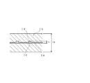
- FIG. 1 and 2 are cross-sectional views showing an example of a positive or negative electrode plate
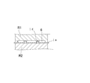
- FIG. 3 is an end view in which the shape of the hole tip of the electrode plate is bent outward.
- the negative electrode for a lithium secondary battery includes, as a negative electrode mixture layer, a material capable of occluding and releasing lithium ions as an active material as a main material, and kneading the material, a binder, a dispersion solvent, and the like.
- the paste is made into a paste and applied to both sides of the foil-like current collector 1a.
- Examples of materials capable of inserting and extracting lithium ions include carbon materials, lithium-aluminum alloys, silicon-based or tin-based lithium alloys, and the like. Among these, it is preferable to use a carbon material for reasons such as a large amount of occlusion / release of lithium ions and a small irreversible capacity.
- a carbon material for reasons such as a large amount of occlusion / release of lithium ions and a small irreversible capacity.
- an aluminum foil is used for the positive electrode and a copper foil is used for the negative electrode in view of electrochemical properties, processability to a foil shape, and cost.
- the positive electrode for a lithium secondary battery includes, as an active material for forming a positive electrode mixture layer, a lithium-containing metal oxide, a lithium-containing metal phosphate compound, or a lithium-containing compound as a main material, the material, a binder, It can be formed by kneading a dispersion solvent or the like into a paste and applying it to both surfaces of the current collector 1a.
- the lithium-containing metal oxide include LiCoO 2 , Li (Ni / Co / Mn) O 2 , and LiMn 2 O 4.
- the lithium-containing metal phosphate compound include LiFePO 4 , LiCoPO 4 , and LiMnPO 4.
- lithium-containing compound examples include LiTi 2 (PO 4 ) 3 and LiFeO 2 .
- LiCoO 2 , Li (Ni / Co / Mn) O 2 , LiMn 2 O 4 , and LiFePO 4 are preferably used in terms of electrochemical characteristics, safety, and cost.
- FIG. 1 and 2 are cross-sectional views of one positive or negative electrode plate comprising a foil-like current collector having a plurality of through-holes having protrusions and a mixture layer.
- t 1 the thickness including the protruding portion of the current collector 1a provided with the protruding hole 1c having the protruding portion 1d around the through hole.
- the thicknesses of the current collector 1a and the mixture layer 1b are combined.
- good proportion of the electrode plate total thickness t 1 is 3% or more with respect to electrode plates total thickness t 0 value obtained by subtracting t 1 from. In particular, 10% or more and 50% or less are more preferable.
- the thickness t 1 of the current collector 1a means that the protrusion 1d around the hole 1c provided in the current collector 1a protrudes only to one surface side of the current collector 1a. It is the height from the non-projecting surface to the tip of the projecting portion 1d (FIG. 1), and when the projecting portion 1d around the hole 1c projects to both surfaces of the current collector 1a, the projecting portion 1d on one surface side This is the height from the tip to the tip of the protrusion 1d on the opposite surface side (FIG. 2). Further, these protrusions and holes may be formed over the entire surface of the current collector, or may be formed in a part leaving a flat foil part of a non-projection surface in part.
- the protruding hole tip 1d ′ is preferably bent into a bent shape. The bending direction may be outside or inside with respect to the hole, but the outside is better as the holding force of the active material.
- the foil cross-sectional shape of the foil protruding hole may be any shape such as a polygonal pyramid, a cylindrical shape, a conical shape, or a combination of these shapes.
- a conical shape is more preferable from the viewpoint of the processing speed, the processing shot life of the processing jig, and the possibility of generation of cutting powder and peeling powder after processing the tip of the protruding hole.
- this foil protrusion hole is a through-hole formed by breaking through the current collector foil, it is preferable because the current collecting effect is improved.
- the through-hole formed by breaking through the current collector foil has a large current charge / discharge compared to the through-hole formed in the current collector foil by punching or the unevenness formed by embossing. Excellent durability such as internal short circuit during cycling.
- the through hole is a circular hole having a diameter t 2 of 50 to 150 ⁇ m, the height t 3 of the protrusion is 50 to 400 ⁇ m, and the distance t 4 between the adjacent through holes is 300 to 2000 ⁇ m.
- the separator that can be used in the lithium secondary battery is one that electrically insulates the positive electrode and the negative electrode to hold the electrolytic solution.
- Examples of the separator include synthetic resins and inorganic fibers, and specific examples thereof include polyethylene and polypropylene films.
- the lithium secondary battery it is preferable to use a non-aqueous electrolyte containing a lithium salt, an ion conductive polymer, or the like as an electrolyte in which the electrode group described above is immersed.
- non-aqueous solvent in the non-aqueous electrolyte containing a lithium salt examples include ethylene carbonate (EC), propylene carbonate (PC), diethyl carbonate (DEC), dimethyl carbonate (DMC), and methyl ethyl carbonate (MEC).
- lithium salts that can be dissolved in the non-aqueous solvent include lithium hexafluorophosphate (LiPF 6 ), lithium borotetrafluoride (LiBF 4 ), and lithium trifluoromethanesulfonate (LiSO 3 CF 4 ).
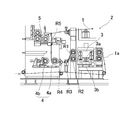
- FIG. 4 is a diagram showing an outline of an electrode manufacturing apparatus used in an electrode manufacturing process in which a current collector foil processing apparatus and a mixture layer forming apparatus are continuously arranged.
- the electrode manufacturing device 2 includes a current collector foil processing device 3, a press roll device 4 for bending the tip shape of the protruding portion inside or outside the hole after current collector processing, and a continuous type after current collector foil processing.
- the coating device 5 for forming the agent layer is continuously arranged in this order along the production line of the current collector 1 serving as a positive electrode or a negative electrode without winding the current collector foil 1a around a roll.
- the press roll apparatus 4 is arrange
- the current collector foil processing device 3 is a device in which a projecting hole 1c, which is a through hole continuously penetrating the current collector foil 1a, is provided.
- This apparatus is composed of a punch 3a disposed perpendicular to the foil surface above or below the current collector foil 1a and a die 3b disposed on the lower surface or upper surface of the current collector foil 1a and having a recess.
- This is a mold.
- a cross section of the mold is shown in FIG.
- a specific mold is constituted by an upper mold 3a ′ and a lower mold 3b ′ in which a plurality of punches 3a and a plurality of dies 3b are arranged.
- the punch 3a and the die 3b are formed on the mold abutting surface 3c.
- Die 3b having a recess of a long depth t 6 than the length t 5 of the protrusions of the punch 3a is provided in the die abutment surfaces 3c of the mating.
- the upper mold 3a ′ and the lower mold 3b ′ are continuously engaged with each other and opened, so that the punch 3a presses the current collecting foil 1a into the recess of the die 3b, thereby collecting the current collecting foil 1a.
- the tip of the punch 3a is preferably conical.
- the press roll device 4 is a press roll device that bends the tip of the projecting hole inward or outward after providing the projecting hole 1c in the current collector foil 1a.
- the press roll device 4 includes a roller 4a that supports a current collector foil 1a provided with a protruding hole, and a pressing roller 4b that can move back and forth with respect to the roller 4a. When the pressing roller 4b presses the current collector foil 1a on the roller 4a, the tip of the protruding hole can be bent inward or outward of the through hole.
- a current collector foil for a lithium secondary battery can be produced by winding the current collector foil without performing a mixture forming step.
- a spacer is provided between the layers of the current collector foil to be wound.
- a plan view of the obtained current collector foil for a lithium secondary battery is shown in FIG.
- the vertical part in the center of the drawing is a part provided with a plurality of through holes, and both side parts are aluminum foil parts where no through holes are provided.
- the coating device 5 is a device that forms the positive or negative electrode mixture layer 1b on the surfaces on both sides of the current collector foil 1a in which the protruding holes are formed.
- a coating device for transferring the mixture paint on the current collector foil 1a by a roll coater, a die coater, etc., a spray device for spraying the mixture paint, or a current collector foil in the coating liquid An immersion apparatus for immersing 1 is used.
- a coating apparatus and a dipping apparatus that can simultaneously form the mixture layer 1b on both sides of the current collector foil 1 are preferable.
- a slit die coater for simultaneous coating on both sides is more preferable.
- the mixture is applied and dried in a drying oven.
- a vertical or horizontal drying furnace can be used.
- the method for producing a lithium secondary battery according to the present invention includes a perforation step, a tip end processing step for a protruding hole, and a mixture layer formation for a continuously supplied current collecting foil using the electrode production apparatus.
- the process is performed continuously.
- the surface of current collection foil does not contact and rub against each other by winding up or unwinding current collection foil. Therefore, the current collector foil cutting powder and the current collector foil falling powder are not generated from the hole tip after the current collector foil processing.
- the current collector foil 1a is transported in contact with the transport rolls R1 to R5 after passing through the perforating process.
- the intermittent conveyance generated in the punching process by the rolls R3 and R4 is returned to the continuous conveyance. Since the through-holes of the current collector foil 1a are densely formed as described above, the through-hole forming surface is subjected to a surface pressure as a whole, and is taken up by a winding roll in contact with the through-hole forming surface.
- the through hole is not blocked. In addition, it can wind up with a winding roll, without contacting a through-hole formation surface.
- a sectional view of such a transport roll is shown in FIG.
- an electrode group is formed by producing an electrode for producing a positive electrode and a negative electrode by the above method, and then laminating or winding the obtained positive electrode and negative electrode through a separator.
- a well-known method can be employ
- Example 1 A positive electrode of a lithium secondary battery was produced by the following method. Olivine type lithium iron phosphate having a secondary particle size of 2 to 3 ⁇ m as a positive electrode active material, 84 parts by weight of the active material, 8 parts by weight of conductive carbon and a mixture of conductive carbon fiber bodies as a conductive agent, As a binder, 8 parts by weight of polyvinylidene fluoride was added. To this, N-methylpyrrolidone was added as a dispersion solvent and kneaded to prepare a positive electrode mixture (positive electrode slurry). An aluminum foil having a thickness of 20 ⁇ m and a width of 150 mm is prepared. This aluminum foil is supplied in a state of being wound around a supply roll.
- the aluminum foil drawn out from the supply roll is subjected to protrusion drilling in the current collector foil processing device 3 portion of the manufacturing apparatus shown in FIG. Perforation was performed such that the foil protrusion height t 1 shown in FIG. 2 was 120 ⁇ m. Thereafter, the perforated aluminum foil was guided to the coating device 5 without operating the press roll device 4.
- the positive electrode slurry was applied to both sides of the processed aluminum foil and dried. In the perforation and coating process, the aluminum foil was continuously supplied from the supply roll, and was continuously guided to the coating process without being wound after the perforation process. Then, the positive electrode for lithium secondary batteries was obtained by pressing and cutting. After coating and drying a positive electrode slurry on both surfaces of an aluminum foil, the positive electrode total thickness t 0 when the press was 160 .mu.m.
- Example 2 A negative electrode of a lithium secondary battery was produced by the following method. To a mixture of 94 parts by weight of graphite powder and 1 part by weight of conductive carbon and conductive carbon fiber as a conductive agent, 5 parts by weight of polyvinylidene fluoride as a binder is added, and N-methyl as a dispersion solvent is added thereto. Pyrrolidone was added and kneaded to prepare a negative electrode mixture (negative electrode slurry).
- a copper foil having a thickness of 10 ⁇ m and a width of 150 mm is prepared.
- This copper foil is supplied in a state wound on a supply roll.
- the copper foil drawn out from the supply roll is subjected to protrusion drilling in the current collector foil processing device 3 portion of the manufacturing apparatus shown in FIG. Perforation was performed so that the foil protrusion height t 1 shown in FIG. 2 was 90 ⁇ m.
- the perforated copper foil was guided to the coating device 5 without operating the press roll device 4.
- the negative electrode slurry was applied to both sides of the processed copper foil and dried. In the perforation and coating process, the copper foil was continuously supplied from the supply roll, and was continuously guided to the coating process without being wound after the perforation process. Then, the negative electrode for lithium secondary batteries was obtained by pressing and cutting.
- the negative electrode total thickness t 0 when pressed after applying and drying the negative electrode slurry on both sides of the copper foil was 120 ⁇ m.
- Example 3 A 3.4 V-10 Ah aluminum laminated film pack type lithium ion battery was produced using the produced positive and negative electrode plates.
- the electrolytic solution one obtained by dissolving 1 mol / l of lithium hexafluorophosphate (LiPF 6 ) in a solution mixed at a volume ratio of EC and MEC of 30:70 was used.
- a woven fabric made of PP resin fiber and having a thickness of 40 ⁇ m was used as the positive / negative electrode separation insulator.
- the obtained lithium ion battery had excellent characteristics for large-current charge / discharge, excellent durability, and safety.
- Example 4 In the manufacturing method of Example 1, after the protrusion drilling process, the press roll device 4 is operated, and the pressing roller 4b is pressed against the aluminum foil on the roller 4a, so that the tip of the protruding hole is bent inside or outside the through hole. It was.
- the foil protrusion height t 1 after processing shown in FIG. 2 was 150 ⁇ m. Otherwise, a positive electrode having a total positive electrode thickness t 0 of 180 ⁇ m was obtained in the same manner as in Example 1.
- Example 5 In the manufacturing method of Example 2, after the protrusion drilling process, the press roll device 4 is operated and the pressing roller 4b is pressed against the copper foil on the roller 4a, so that the tip of the protruding hole is bent inward or outward of the through hole. It was.
- the foil protrusion height t 1 after processing shown in FIG. 2 was 120 ⁇ m. Otherwise, the negative electrode having the total negative electrode thickness t 0 of 140 ⁇ m was obtained in the same manner as in Example 1.
- Example 6 A 3.4 V-10 Ah aluminum laminated film pack type lithium ion battery was produced using the produced positive and negative electrode plates.
- the electrolytic solution one obtained by dissolving 1 mol / l of lithium hexafluorophosphate (LiPF 6 ) in a solution mixed at a volume ratio of EC and MEC of 30:70 was used.
- a woven fabric made of PP resin fiber and having a thickness of 40 ⁇ m was used as the positive / negative electrode separation insulator.
- the obtained lithium ion battery was more excellent in charge / discharge of a large current than the battery of Example 3, was excellent in durability, and was safe.
- Example 1 Comparative Example 1
- the current collector foils were wound around rolls, respectively, after the protrusion drilling process. Thereafter, using the wound roll as a foil supply roll, a positive electrode plate and a negative electrode plate were produced in the same manner as in Example 1 and Example 2, respectively.
- a lithium ion battery was obtained by the same method as in Example 3. The obtained lithium ion battery had excellent characteristics for large current charge / discharge in the initial charge / discharge, but was inferior in durability and safety due to an internal short circuit during the cycle.
- the method for producing a lithium secondary battery of the present invention is a method for producing an electrode in which an unsafe event such as an internal short circuit does not occur in a lithium secondary battery that has a high capacity and can be repeatedly charged and discharged with a large current. It can be applied to the production of lithium secondary batteries for many future uses.
Landscapes
- Chemical & Material Sciences (AREA)
- Chemical Kinetics & Catalysis (AREA)
- Electrochemistry (AREA)
- General Chemical & Material Sciences (AREA)
- Engineering & Computer Science (AREA)
- Manufacturing & Machinery (AREA)
- Materials Engineering (AREA)
- Physics & Mathematics (AREA)
- Condensed Matter Physics & Semiconductors (AREA)
- General Physics & Mathematics (AREA)
- Inorganic Chemistry (AREA)
- Battery Electrode And Active Subsutance (AREA)
- Cell Electrode Carriers And Collectors (AREA)
- Secondary Cells (AREA)
Abstract
Description
近年、このリチウム二次電池の高容量化が求められる一方、パワー用途の電池として大電流充放電に供されることとなり、負極上で金属リチウムが析出して内部短絡に至り、最悪の場合発熱や発火事故の生じるおそれがある。
従来は、リチウム金属酸化物正極材または炭素系負極材自体の高容量化により、負極上で金属リチウムを析出させないように負極側で余裕を持って吸蔵または放出反応が可能なように工夫してきた。または活物質粒子の小粒径化による比表面積の増加や電極設計による電極面積の増加等の工夫がなされてきた。これらの工夫によって電池設計としては安全な方向へ進んだものの、電池製造面での活物質脱落や剥離による短絡対策に対しては不十分であったために、さらに集電体に工夫を施したものが提案されてきた。例えば網状にしたり、穴を開けたパンチングメタルやラス加工を施したもの(特許文献1)、さらには表面に凹凸を有する金属箔を使用したりしたもの(特許文献2)、集電体を貫通する複数の孔を有し、該孔は孔の周囲が箔状集電体の少なくとも一方の面側へ突出してなり、上記箔状集電体の上記孔周囲の突出部を含めた厚さが、上記負極または上記正極の該集電体および該合剤層を合わせた1枚の極板総厚さの3%をこえ25%以下としたもの(特許文献3)等が知られている。
また、リチウムを吸蔵・放出する活物質膜を集電体箔上に真空プロセスで形成する第1の工程と、この活物質膜表面の突起物を直線状刃先を有する刃物で除去する第2の工程とを有し、第2の工程は、直線状刃先を活物質膜の表面から所定の距離に維持した状態で活物質膜を移動させることにより突起物を除去する工程であるリチウム電池用電極の製造方法が開示されている(特許文献5)。
上記電極製造工程は、集電箔を貫通し、かつ少なくとも一方の集電箔面側に突出する突出部を有する複数の貫通孔を形成する穿孔工程と、この集電箔に合剤層を形成する合剤形成工程とを備え、
上記穿孔工程後に穿孔された集電箔を巻き取ることなく連続して合剤形成工程を行なうことを特徴とする製造方法である。
特に、上記穿孔工程が集電箔を突き破って貫通孔を形成する工程であることを特徴とする。
また、上記リチウム二次電池用集電箔の製造方法、ならびにこの方法で製造されるリチウム二次電池用集電箔であることを特徴とする。
また、本発明の製造法によって得られるリチウム二次電池は、電池構成部材として正極および負極箔状集電体が貫通する複数の孔を有し、該孔は孔の周囲が箔状集電体の少なくとも一方の面側へ突出してなり、この孔周囲の突出部により活物質合剤へのアンカー効果を生みだし、集電体表面に形成する活物質合剤層の保持能力が向上し、合剤層の剥離を防止することができ、より多くの活物質を電池内に収納することが可能である。
また正極または負極箔状集電体を貫通する複数の孔の周囲に突出部を有する加工を施した後、該集電箔を巻き取ることなく、また搬送時に該突出部が搬送機材に接触することなく、連続的に箔加工と箔上への活物質合剤層の形成を可能とし、また、該突出部の先端部が孔の内側または外側に屈曲する形状に加工するものである。これらのリチウム二次電池の電極製造法によって得られるリチウム二次電池は、充放電中に正極または負極合剤層が膨張収縮しても、それぞれの粒子間や集電体との密着性が維持されることならびに箔加工時の金属粉が発生せず、内部短絡などの安全性向上させることができる。さらに突出部孔の先端形状が内側または外側に屈曲させることにより、さらに活物質の保持能力は向上すると同時に先端が丸くなっていることで孔先端部が万が一、電極外に飛び出してもセパレータを突き破って対極との内部短絡を生じることがない。
上記リチウム二次電池用負極は、負極合剤層として、活物質となるリチウムイオンの吸蔵・放出が可能な材料を主材料とし、該材料と、結着剤と、分散溶媒等とを混練してペースト状にし、箔状集電体1aの両面に塗布して製造される。
リチウムイオンの吸蔵・放出が可能な材料としては、炭素材、リチウム-アルミニウム合金、シリコン系またはスズ系リチウム合金などを挙げることができる。この中で、リチウムイオンの吸蔵・放出量が多く、不可逆容量が小さいなどの理由から、炭素材を用いることが好ましい。また、本発明に用いることができる集電体1aとしては、電気化学的性質、箔状への加工性やコスト面から、正極ではアルミ箔、負極では銅箔が用いられている。
リチウム含有金属酸化物としては、LiCoO2、Li(Ni/Co/Mn)O2、LiMn2O4などが挙げられ、リチウム含有金属リン酸化合物としては、LiFePO4、LiCoPO4、LiMnPO4などが挙げられ、リチウム含有化合物としては、LiTi2(PO4)3、LiFeO2などが挙げられる。この中で、電気化学特性、安全性やコスト面で、LiCoO2、Li(Ni/Co/Mn)O2、LiMn2O4、LiFePO4を用いることが好ましい。
貫通孔周囲に突出部1dを有する突出孔1cが設けられた集電体1aの突出部を含めた厚さをt1とすると、集電体1aおよび合剤層1bの厚さを合わせた1枚の極板総厚さt0からt1を差し引いた値に対する極板総厚さt1の割合が3%以上であることがよい。特に10%以上、50%以下がより好ましい。
ここで集電体1aの厚さt1とは、集電体1aに設けられた孔1c周囲の突出部1dが集電体1aの一方の面側のみへ突出している場合は、孔1cの非突出面から突出部1dの先端までの高さであり(図1)、孔1c周囲の突出部1dが集電体1aの両面へ突出している場合は、一方の面側の突出部1dの先端から反対の面側の突出部1dの先端までの高さである(図2)。またこれらの突出部と孔とは、集電体の全面にわたって形成されていても、また一部に非突出面の平坦な箔部を残して一部分に形成されていてもよい。好ましくは電池製造上の集電箔の強度の関係で、一部に形成されている方がより良い。特に、集電箔の両幅部分には突出孔を形成することなく、平坦な箔部分を残すことが好ましい。本発明の製造方法において、両幅部分の平坦な箔部分が搬送ローラに挟持され、突出孔の先端部分が搬送用ロールに接触しない。
さらに図3に示すように電池内での短絡防止から、該突出孔先端部1d'は屈曲形状に曲げられているものがよい。曲げる方向は孔に対して外側でも内側でもよいが、活物質の保持力としては外側がより良い。
また、この箔突出孔は、集電箔を突き破って形成される貫通孔であることが集電効果を向上させるので好ましい。集電箔を突き破って形成される貫通孔は、集電箔にパンチング加工で形成される貫通孔またはエンボス加工で形成される凹凸に比較して、リチウム二次電池としたときの大電流充放電に優れ、サイクル時の内部短絡等の耐久性に優れる。
貫通孔分布を上記範囲に設けることにより、貫通孔形成面が全体として面圧を受けることになり、例えば直接貫通孔形成面に接して巻き取りロールで巻き取っても貫通孔が塞がれることがない。
また、上記非水溶媒に溶解できるリチウム塩としては、六フッ化リン酸リチウム(LiPF6)、ホウ四フッ化リチウム(LiBF4)、トリフルオロメタンスルホン酸リチウム(LiSO3CF4)等が挙げられる。
電極製造装置2は、集電箔加工装置3と、集電箔加工後に突出部の先端形状を孔の内側または外側に屈曲させるためのプレスロール装置4と、集電箔加工後に連続式に合剤層を形成する塗工装置5とが正極または負極となる集電体1の製造ラインに沿って該集電箔1aを途中でロールに巻き取ることなくこの順に連続的に配置されている。なお、プレスロール装置4は必要に応じて配置される。
金型の断面を図6に示す。複数のポンチ3aおよび複数のダイ3bが配列された上型金型3a’および下型金型3b’とで具体的な金型が構成される。
ポンチ3aおよびダイ3bは、金型衝合面3cに形成されている。ポンチ3aの突出部の長さt5よりも長い深さt6の凹部を有するダイ3bが相手側の金型衝合面3cに設けられている。
上型金型3a’および下型金型3b’が相互に衝合および型開きを連続的に繰り返すことで、ポンチ3aがダイ3bの凹部に集電箔1aを加圧することで集電箔1aに突出孔1cが設けられる。ポンチ3aの先端部は円錐形にすることが好ましい。
合剤を塗工後に乾燥炉にて乾燥する。乾燥炉としては縦型または横型の乾燥炉を使用することができる。
なお、貫通孔形成面に接することなく巻き取りロールで巻き取ることができる。そのような搬送ロールの断面図を図5に示す。穿孔工程で形成された突出孔1cの先端加工の突出部1dが箔搬送用のロールR1のロール表面に接触することのないように、搬送ロールR1に彫り込み6を入れた形状とする。先端加工の突出部1dが集電箔両面に存在する場合は、搬送ロールR1およびR2の双方に彫り込みを入れる。
本発明の連続式の箔加工・合剤形成装置により製造される電極は、加工箔の切り粉や脱落粉が皆無となるので、内部短絡によるリチウム二次電池の不安全性が解消できる。
リチウム二次電池の正極を以下の方法で製造した。
二次粒子径が2~3μmのオリビン型リン酸鉄リチウムを正極活物質とし、該活物質84重量部に、導電剤として8重量部の導電性カーボンおよび導電性カーボン繊維体の混合体と、結着剤として8重量部のポリフッ化ビニリデンを添加した。これに分散溶媒として、N-メチルピロリドンを添加し、混練して、正極合剤(正極スラリー)を作製した。
20μm厚さで、150mm幅のアルミニウム箔を準備する。このアルミニウム箔は供給ロールに巻かれた状態で供給される。
供給ロールから引き出されたアルミニウム箔は、図4に示す製造装置の集電箔加工装置3部分において突起穿孔加工を施す。図2に示す箔突起高さt1が120μmとなるように穿孔した。その後、プレスロール装置4を作動させることなく、穿孔されたアルミニウム箔を塗工装置5に導いた。上記正極スラリーを該加工アルミニウム箔の両面に塗布、乾燥した。穿孔および塗工工程において、アルミニウム箔は連続して供給ロールから供給され、穿孔工程後に巻き取られることなく、連続して塗工工程に導かれた。その後、プレス、裁断してリチウム二次電池用の正極を得た。アルミニウム箔の両面に正極スラリーを塗布・乾燥後、プレスした時の正極総厚さt0は160μmであった。
リチウム二次電池の負極を以下の方法で製造した。
黒鉛粉末94重量部および導電剤として1重量部の導電性カーボンおよび導電性カーボン繊維体の混合体に、結着剤として5重量部のポリフッ化ビニリデンを添加し、これに分散溶媒としてN-メチルピロリドンを添加し混練して、負極合剤(負極スラリー)を作製した。
供給ロールから引き出された銅箔は、図4に示す製造装置の集電箔加工装置3部分において突起穿孔加工を施す。図2に示す箔突起高さt1が90μmとなるように穿孔した。その後、プレスロール装置4を作動させることなく、穿孔された銅箔を塗工装置5に導いた。上記負極スラリーを該加工銅箔の両面に塗布、乾燥した。穿孔および塗工工程において、銅箔は連続して供給ロールから供給され、穿孔工程後に巻き取られることなく、連続して塗工工程に導かれた。その後、プレス、裁断してリチウム二次電池用の負極を得た。銅箔の両面に負極スラリーを塗布・乾燥後、プレスした時の負極総厚さt0は120μmであった。
作製した正、負極板を用いて3.4V-10Ahのアルミラミネートフィルムパック式リチウムイオン電池を作製した。電解液にはEC、MEC体積比で30:70に混合した溶液中に6フッ化リン酸リチウム(LiPF6)を1mol/l溶解したものを用いた。正・負極板隔離絶縁体には、PP樹脂繊維製の厚さ40μmの織布を用いた。
得られたリチウムイオン電池は、大電流充放電に優れた特性であり、耐久性に優れ、また安全性が得られた。
実施例1の製造方法において、突起穿孔加工後に、プレスロール装置4を作動させ、押圧ローラ4bをローラ4a上のアルミニウム箔に押し付けることで、突出孔の先端を貫通孔の内側または外側に屈曲させた。図2に示す加工後の箔突起高さt1は150μmであった。それ以外は実施例1と同一の方法で正極総厚さt0が180μmの正極を得た。
実施例2の製造方法において、突起穿孔加工後に、プレスロール装置4を作動させ、押圧ローラ4bをローラ4a上の銅箔に押し付けることで、突出孔の先端を貫通孔の内側または外側に屈曲させた。図2に示す加工後の箔突起高さt1は120μmであった。それ以外は実施例1と同一の方法で負極総厚さt0が140μmの負極を得た。
作製した正、負極板を用いて3.4V-10Ahのアルミラミネートフィルムパック式リチウムイオン電池を作製した。電解液にはEC、MEC体積比で30:70に混合した溶液中に6フッ化リン酸リチウム(LiPF6)を1mol/l溶解したものを用いた。正・負極板隔離絶縁体には、PP樹脂繊維製の厚さ40μmの織布を用いた。
得られたリチウムイオン電池は、実施例3の電池よりさらに大電流充放電に優れた特性であり、耐久性に優れ、また安全性が得られた。
実施例1および実施例2の製造方法において、突起穿孔加工後に、集電箔をそれぞれロールに巻き取った。その後、この巻き取ったロールを箔供給ロールとして用いて、実施例1および実施例2と同一の方法で正極板および負極板をそれぞれ製造した。
次に、実施例3と同一の方法でリチウムイオン電池を得た。
得られたリチウムイオン電池は、初期の充放電は大電流充放電に優れた特性であったが、サイクル時の内部短絡等で耐久性および安全性が劣っていた。
1a 正または負極集電箔
1b 正または負極合剤層
1c 孔
1d 突出部
1d' 突出先端部屈曲形状例
2 電極製造装置
3 金型による箔加工装置
4 プレスロール装置
5 塗工装置
6 彫り込み
Claims (13)
- 正極および負極を製造する電極製造工程と、
前記正極および負極をセパレータを介して積層あるいは捲回することにより電極群を形成する工程と、
前記電極群を電解液に浸漬する工程とを備えてなるリチウム二次電池の製造方法であって、
前記電極製造工程は、集電箔を貫通し、かつ少なくとも一方の集電箔面側に突出する突出部を有する複数の貫通孔を形成する穿孔工程と、この穿孔された集電箔に合剤層を形成する合剤形成工程とを備え、
前記穿孔工程後に穿孔された前記集電箔を巻き取ることなく連続して前記合剤形成工程を行なうことを特徴とするリチウム二次電池の製造方法。 - 前記穿孔工程が前記集電箔を突き破って貫通孔を形成する工程であることを特徴とする請求項1記載のリチウム二次電池の製造方法。
- 前記集電箔を突き破って貫通孔を形成する工程は、上型金型および下型金型の一方の衝合面に形成されるポンチと、このポンチ突出部の長さよりも長い深さを有する凹部が前記上型金型および下型金型の他方の衝合面に形成されるダイとから構成される集電箔加工装置を用いて、前記上型金型および下型金型が前記集電箔を挟んで前記ポンチと前記ダイとが相互に衝合することにより貫通孔が設けられる工程であることを特徴とする請求項2記載のリチウム二次電池の製造方法。
- 前記複数の貫通孔は、直径が50~150μmの円孔であり、前記突出部の高さが50~400μmであり、隣接する貫通孔との距離が300~2000μmであることを特徴とする請求項3記載のリチウム二次電池の製造方法。
- 前記集電箔の幅方向両幅部分は、前記複数の貫通孔が形成されておらず平坦な箔部分であることを特徴とする請求項1記載のリチウム二次電池の製造方法。
- 前記集電箔がアルミニウム箔または銅箔であることを特徴とする請求項1記載のリチウム二次電池の製造方法。
- 前記穿孔工程後に前記突出部が集電箔搬送用の機材部に接触することなく集電箔が搬送されることを特徴とする請求項1記載のリチウム二次電池の製造方法。
- 前記穿孔工程後に前記突出部の先端を貫通孔の内側または外側に屈曲するような形状に加工する工程を有することを特徴とする請求項1記載のリチウム二次電池の製造方法。
- 前記合剤形成工程は、突出孔が形成された集電箔上の両側の表面に正または負極合剤層を形成する工程と、乾燥炉にて乾燥する乾燥工程とを備えることを特徴とする請求項1記載のリチウム二次電池の製造方法。
- 金属箔の主面を貫通し、かつ少なくとも一方の主面側に突出する突出部を有する複数の貫通孔を形成する穿孔工程を備えるリチウム二次電池用集電箔の製造方法であって、
前記貫通孔が前記集電箔を突き破って形成される貫通孔であり、
前記貫通孔を形成する工程は、上型金型および下型金型の一方の衝合面に形成されるポンチと、このポンチ突出部の長さよりも長い深さを有する凹部が前記上型金型および下型金型の他方の衝合面に形成されるダイとから構成される集電箔加工装置を用いて、前記上型金型および下型金型が前記集電箔を挟んで前記ポンチと前記ダイとが相互に衝合することにより貫通孔が設けられる工程であることを特徴とするリチウム二次電池用集電箔の製造方法。 - 金属箔の箔面を貫通し、かつ少なくとも一方の箔面側に突出する突出部を有する複数の貫通孔を有するリチウム二次電池用集電箔であって、
前記貫通孔が前記集電箔を突き破って形成される複数の貫通孔であり、前記複数の貫通孔は、直径が50~150μmの円孔であり、前記突出部の高さが50~400μmであり、隣接する貫通孔との距離が300~2000μmであることを特徴とするリチウム二次電池用集電箔。 - 前記集電箔の幅方向両幅部分は、前記複数の貫通孔が形成されておらず平坦な箔部分であることを特徴とする請求項11記載のリチウム二次電池用集電箔。
- 前記集電箔がアルミニウム箔または銅箔であることを特徴とする請求項11または請求項12記載のリチウム二次電池用集電箔。
Priority Applications (10)
| Application Number | Priority Date | Filing Date | Title |
|---|---|---|---|
| JP2011537294A JP5682039B2 (ja) | 2009-10-23 | 2010-10-21 | リチウム二次電池およびリチウム二次電池用集電箔の製造方法、ならびにリチウム二次電池用集電箔 |
| CN201080047627.2A CN102598368B (zh) | 2009-10-23 | 2010-10-21 | 锂二次电池以及锂二次电池用集电箔的制造方法、以及锂二次电池用集电箔 |
| KR1020127013150A KR101758405B1 (ko) | 2009-10-23 | 2010-10-21 | 리튬 이차 전지 및 리튬 이차 전지용 집전박의 제조 방법 및 리튬 이차 전지용 집전박 |
| US13/503,629 US9496583B2 (en) | 2009-10-23 | 2010-10-21 | Lithium secondary battery, method for producing power collection foil for same, and power collection foil for same |
| CA2778558A CA2778558C (en) | 2009-10-23 | 2010-10-21 | Lithium secondary battery, method for producing power collection foil for same, and power collection foil for same |
| EP10825002.8A EP2492994B1 (en) | 2009-10-23 | 2010-10-21 | Method for manufacturing a lithium secondary battery and apparatus therefor |
| DK10825002.8T DK2492994T3 (en) | 2009-10-23 | 2010-10-21 | PROCEDURE FOR MANUFACTURING A LITHIUM SECONDARY BATTERY AND APPARATUS |
| PL10825002T PL2492994T3 (pl) | 2009-10-23 | 2010-10-21 | Sposób wytwarzania wtórnego ogniwa litowego i urządzenie dla niego |
| ES10825002T ES2704651T3 (es) | 2009-10-23 | 2010-10-21 | Método para fabricar una batería secundaria de litio y su aparato |
| US15/286,433 US10879567B2 (en) | 2009-10-23 | 2016-10-05 | Lithium secondary battery, method for producing power collection foil for same, and power collection foil for same |
Applications Claiming Priority (2)
| Application Number | Priority Date | Filing Date | Title |
|---|---|---|---|
| JP2009244054 | 2009-10-23 | ||
| JP2009-244054 | 2009-10-23 |
Related Child Applications (2)
| Application Number | Title | Priority Date | Filing Date |
|---|---|---|---|
| US13/503,629 A-371-Of-International US9496583B2 (en) | 2009-10-23 | 2010-10-21 | Lithium secondary battery, method for producing power collection foil for same, and power collection foil for same |
| US15/286,433 Continuation US10879567B2 (en) | 2009-10-23 | 2016-10-05 | Lithium secondary battery, method for producing power collection foil for same, and power collection foil for same |
Publications (1)
| Publication Number | Publication Date |
|---|---|
| WO2011049153A1 true WO2011049153A1 (ja) | 2011-04-28 |
Family
ID=43900376
Family Applications (1)
| Application Number | Title | Priority Date | Filing Date |
|---|---|---|---|
| PCT/JP2010/068544 WO2011049153A1 (ja) | 2009-10-23 | 2010-10-21 | リチウム二次電池およびリチウム二次電池用集電箔の製造方法、ならびにリチウム二次電池用集電箔 |
Country Status (11)
| Country | Link |
|---|---|
| US (2) | US9496583B2 (ja) |
| EP (1) | EP2492994B1 (ja) |
| JP (1) | JP5682039B2 (ja) |
| KR (1) | KR101758405B1 (ja) |
| CN (1) | CN102598368B (ja) |
| CA (1) | CA2778558C (ja) |
| DK (1) | DK2492994T3 (ja) |
| ES (1) | ES2704651T3 (ja) |
| HU (1) | HUE043029T2 (ja) |
| PL (1) | PL2492994T3 (ja) |
| WO (1) | WO2011049153A1 (ja) |
Cited By (11)
| Publication number | Priority date | Publication date | Assignee | Title |
|---|---|---|---|---|
| CN102244267A (zh) * | 2011-05-20 | 2011-11-16 | 高新峰 | 二次电池的极板及其制备方法 |
| JP2014026931A (ja) * | 2012-07-30 | 2014-02-06 | Nissan Motor Co Ltd | 電極及び電極の製造方法 |
| WO2014073221A1 (ja) | 2012-11-09 | 2014-05-15 | エス・イー・アイ株式会社 | リチウム二次電池用電極およびリチウム二次電池 |
| WO2014192637A1 (ja) * | 2013-05-31 | 2014-12-04 | 株式会社安永 | 非水電解質二次電池用電極及び非水電解質二次電池用電極の製造方法 |
| JP2015215977A (ja) * | 2014-05-08 | 2015-12-03 | エス・イー・アイ株式会社 | リチウム二次電池 |
| JP2017027689A (ja) * | 2015-07-17 | 2017-02-02 | エス・イー・アイ株式会社 | リチウム二次電池 |
| JP2017117731A (ja) * | 2015-12-25 | 2017-06-29 | 株式会社安永 | 蓄電デバイス用電極の製造装置、蓄電デバイス用電極の製造方法、金属箔加工装置、及び穴あき金属箔の製造方法 |
| CN107342394A (zh) * | 2017-07-26 | 2017-11-10 | 湖北猛狮新能源科技有限公司 | 一种锂离子电池双面连续涂布设备及其涂布方法 |
| KR20180020857A (ko) | 2014-05-30 | 2018-02-28 | 에스 이 아이 가부시키가이샤 | 전극 재료 및 그의 제조 방법, 및 리튬 전지 |
| WO2018131094A1 (ja) | 2017-01-11 | 2018-07-19 | エス・イー・アイ株式会社 | 電気化学デバイス |
| US10403893B2 (en) | 2013-08-21 | 2019-09-03 | Hydro-Quebec | Positive electrode material for lithium secondary battery |
Families Citing this family (9)
| Publication number | Priority date | Publication date | Assignee | Title |
|---|---|---|---|---|
| KR101598650B1 (ko) * | 2012-08-23 | 2016-03-03 | 주식회사 엘지화학 | 음극 및 이를 포함하는 고용량 리튬이차전지 |
| CN103357548B (zh) * | 2013-07-02 | 2016-01-06 | 徐敖奎 | 一种微孔基材电池的制作工艺及该工艺中采用的双面涂布机 |
| JP6376441B2 (ja) * | 2014-05-22 | 2018-08-22 | 株式会社Gsユアサ | 蓄電素子及び蓄電素子の製造方法 |
| CN107431236A (zh) | 2015-03-30 | 2017-12-01 | 日立化成株式会社 | 锂离子二次电池及其制造方法 |
| JP6592506B2 (ja) * | 2015-03-31 | 2019-10-16 | 富士フイルム株式会社 | アルミニウム板および蓄電デバイス用集電体 |
| JP6776530B2 (ja) * | 2015-12-14 | 2020-10-28 | 株式会社村田製作所 | 電池、電池パック、電子機器、電動車両、蓄電装置および電力システム |
| CN111108636B (zh) * | 2017-09-21 | 2023-09-19 | 日本电气株式会社 | 集电体和使用该集电体的电池 |
| EP3576191B1 (en) | 2018-05-31 | 2022-10-05 | Panasonic Intellectual Property Management Co., Ltd. | Lithium secondary battery |
| JP7301809B2 (ja) * | 2020-11-30 | 2023-07-03 | Apb株式会社 | 電池用電極の製造装置 |
Citations (11)
| Publication number | Priority date | Publication date | Assignee | Title |
|---|---|---|---|---|
| JPH0896806A (ja) | 1994-07-28 | 1996-04-12 | Matsushita Electric Ind Co Ltd | ペーストの塗着装置および方法 |
| JPH09289021A (ja) * | 1996-02-20 | 1997-11-04 | Toshiba Battery Co Ltd | ペースト式電極、アルカリ二次電池及びアルカリ二次電池の製造方法 |
| JPH10106580A (ja) * | 1996-10-03 | 1998-04-24 | Katayama Tokushu Kogyo Kk | 電池電極用基板の製造方法および電池電極用基板 |
| JPH11185763A (ja) * | 1997-12-25 | 1999-07-09 | Matsushita Electric Ind Co Ltd | 電池用電極芯板とその製造方法および電池 |
| JPH11260375A (ja) | 1998-03-16 | 1999-09-24 | Osaka Gas Co Ltd | 電池活物質保持材及びその製造方法 |
| JP2001357856A (ja) * | 2000-06-14 | 2001-12-26 | Ishikawajima Harima Heavy Ind Co Ltd | 立体多孔金属箔、この金属箔の加工方法及びその加工装置 |
| JP2004079500A (ja) * | 2002-06-21 | 2004-03-11 | Hitachi Maxell Ltd | 電気化学素子用の電極およびこれを用いた電池 |
| JP2004234909A (ja) * | 2003-01-28 | 2004-08-19 | Hitachi Maxell Ltd | 電気化学素子用の電極およびこれを用いた電池 |
| JP2004342519A (ja) | 2003-05-16 | 2004-12-02 | M & G Eco Battery Institute Co Ltd | ペースト式薄型電極を用いた電池とその製造方法 |
| JP2008004281A (ja) | 2006-06-20 | 2008-01-10 | Matsushita Electric Ind Co Ltd | リチウム電池用電極の製造方法 |
| JP2008311171A (ja) | 2007-06-18 | 2008-12-25 | Sei Kk | リチウム二次電池 |
Family Cites Families (8)
| Publication number | Priority date | Publication date | Assignee | Title |
|---|---|---|---|---|
| CA2202604C (fr) * | 1997-04-14 | 2000-12-26 | Hydro-Quebec | Feuillard d'anode alliee et dense a relaxation locale de stress |
| CN1167157C (zh) * | 1998-05-29 | 2004-09-15 | 松下电器产业株式会社 | 不烧结型电极及其制造方法 |
| JP3016769B1 (ja) * | 1998-12-02 | 2000-03-06 | 片山特殊工業株式会社 | 電池用電極板の製造方法、該方法により製造された電極板および該電極板を備えた電池 |
| JP3838878B2 (ja) * | 2000-04-28 | 2006-10-25 | 松下電器産業株式会社 | 電池用電極板およびその製造方法 |
| JP2003017111A (ja) * | 2001-07-04 | 2003-01-17 | Toray Eng Co Ltd | 二次電池および二次電池製造方法ならびに二次電池製造装置 |
| CN100541875C (zh) * | 2005-05-09 | 2009-09-16 | 松下电器产业株式会社 | 电极合剂浆料的涂布方法及涂布装置 |
| EP1994589B1 (en) * | 2006-02-22 | 2010-05-12 | Teck Metals Ltd. | Method and apparatus for continuous manufacture of battery grids |
| EP2099043B1 (en) * | 2006-12-27 | 2019-11-06 | JM Energy Corporation | Coated electrode and organic electrolyte capacitor |
-
2010
- 2010-10-21 HU HUE10825002A patent/HUE043029T2/hu unknown
- 2010-10-21 KR KR1020127013150A patent/KR101758405B1/ko active IP Right Grant
- 2010-10-21 DK DK10825002.8T patent/DK2492994T3/en active
- 2010-10-21 PL PL10825002T patent/PL2492994T3/pl unknown
- 2010-10-21 US US13/503,629 patent/US9496583B2/en active Active
- 2010-10-21 EP EP10825002.8A patent/EP2492994B1/en active Active
- 2010-10-21 ES ES10825002T patent/ES2704651T3/es active Active
- 2010-10-21 CN CN201080047627.2A patent/CN102598368B/zh not_active Expired - Fee Related
- 2010-10-21 WO PCT/JP2010/068544 patent/WO2011049153A1/ja active Application Filing
- 2010-10-21 CA CA2778558A patent/CA2778558C/en active Active
- 2010-10-21 JP JP2011537294A patent/JP5682039B2/ja active Active
-
2016
- 2016-10-05 US US15/286,433 patent/US10879567B2/en active Active
Patent Citations (11)
| Publication number | Priority date | Publication date | Assignee | Title |
|---|---|---|---|---|
| JPH0896806A (ja) | 1994-07-28 | 1996-04-12 | Matsushita Electric Ind Co Ltd | ペーストの塗着装置および方法 |
| JPH09289021A (ja) * | 1996-02-20 | 1997-11-04 | Toshiba Battery Co Ltd | ペースト式電極、アルカリ二次電池及びアルカリ二次電池の製造方法 |
| JPH10106580A (ja) * | 1996-10-03 | 1998-04-24 | Katayama Tokushu Kogyo Kk | 電池電極用基板の製造方法および電池電極用基板 |
| JPH11185763A (ja) * | 1997-12-25 | 1999-07-09 | Matsushita Electric Ind Co Ltd | 電池用電極芯板とその製造方法および電池 |
| JPH11260375A (ja) | 1998-03-16 | 1999-09-24 | Osaka Gas Co Ltd | 電池活物質保持材及びその製造方法 |
| JP2001357856A (ja) * | 2000-06-14 | 2001-12-26 | Ishikawajima Harima Heavy Ind Co Ltd | 立体多孔金属箔、この金属箔の加工方法及びその加工装置 |
| JP2004079500A (ja) * | 2002-06-21 | 2004-03-11 | Hitachi Maxell Ltd | 電気化学素子用の電極およびこれを用いた電池 |
| JP2004234909A (ja) * | 2003-01-28 | 2004-08-19 | Hitachi Maxell Ltd | 電気化学素子用の電極およびこれを用いた電池 |
| JP2004342519A (ja) | 2003-05-16 | 2004-12-02 | M & G Eco Battery Institute Co Ltd | ペースト式薄型電極を用いた電池とその製造方法 |
| JP2008004281A (ja) | 2006-06-20 | 2008-01-10 | Matsushita Electric Ind Co Ltd | リチウム電池用電極の製造方法 |
| JP2008311171A (ja) | 2007-06-18 | 2008-12-25 | Sei Kk | リチウム二次電池 |
Non-Patent Citations (1)
| Title |
|---|
| See also references of EP2492994A4 |
Cited By (16)
| Publication number | Priority date | Publication date | Assignee | Title |
|---|---|---|---|---|
| CN102244267A (zh) * | 2011-05-20 | 2011-11-16 | 高新峰 | 二次电池的极板及其制备方法 |
| JP2014026931A (ja) * | 2012-07-30 | 2014-02-06 | Nissan Motor Co Ltd | 電極及び電極の製造方法 |
| WO2014073221A1 (ja) | 2012-11-09 | 2014-05-15 | エス・イー・アイ株式会社 | リチウム二次電池用電極およびリチウム二次電池 |
| US9660269B2 (en) | 2012-11-09 | 2017-05-23 | Sei Corporation | Electrode for lithium secondary battery and lithium secondary battery |
| JPWO2014192637A1 (ja) * | 2013-05-31 | 2017-02-23 | 株式会社安永 | 非水電解質二次電池用電極及び非水電解質二次電池用電極の製造方法 |
| WO2014192637A1 (ja) * | 2013-05-31 | 2014-12-04 | 株式会社安永 | 非水電解質二次電池用電極及び非水電解質二次電池用電極の製造方法 |
| US10403893B2 (en) | 2013-08-21 | 2019-09-03 | Hydro-Quebec | Positive electrode material for lithium secondary battery |
| JP2015215977A (ja) * | 2014-05-08 | 2015-12-03 | エス・イー・アイ株式会社 | リチウム二次電池 |
| WO2015170785A3 (ja) * | 2014-05-08 | 2015-12-30 | エス・イー・アイ株式会社 | リチウム二次電池 |
| KR20180020857A (ko) | 2014-05-30 | 2018-02-28 | 에스 이 아이 가부시키가이샤 | 전극 재료 및 그의 제조 방법, 및 리튬 전지 |
| JP2017027689A (ja) * | 2015-07-17 | 2017-02-02 | エス・イー・アイ株式会社 | リチウム二次電池 |
| JP2017117731A (ja) * | 2015-12-25 | 2017-06-29 | 株式会社安永 | 蓄電デバイス用電極の製造装置、蓄電デバイス用電極の製造方法、金属箔加工装置、及び穴あき金属箔の製造方法 |
| WO2018131094A1 (ja) | 2017-01-11 | 2018-07-19 | エス・イー・アイ株式会社 | 電気化学デバイス |
| KR20190101999A (ko) | 2017-01-11 | 2019-09-02 | 에스 이 아이 가부시키가이샤 | 전기 화학 디바이스 |
| CN107342394A (zh) * | 2017-07-26 | 2017-11-10 | 湖北猛狮新能源科技有限公司 | 一种锂离子电池双面连续涂布设备及其涂布方法 |
| CN107342394B (zh) * | 2017-07-26 | 2023-07-04 | 湖北猛狮新能源科技有限公司 | 一种锂离子电池双面连续涂布设备及其涂布方法 |
Also Published As
| Publication number | Publication date |
|---|---|
| KR20120093976A (ko) | 2012-08-23 |
| US20170025704A1 (en) | 2017-01-26 |
| US20120210548A1 (en) | 2012-08-23 |
| HUE043029T2 (hu) | 2019-07-29 |
| JP5682039B2 (ja) | 2015-03-11 |
| CN102598368A (zh) | 2012-07-18 |
| US10879567B2 (en) | 2020-12-29 |
| PL2492994T3 (pl) | 2019-04-30 |
| KR101758405B1 (ko) | 2017-07-14 |
| CN102598368B (zh) | 2014-09-17 |
| JPWO2011049153A1 (ja) | 2013-03-14 |
| CA2778558C (en) | 2019-07-09 |
| ES2704651T3 (es) | 2019-03-19 |
| EP2492994A1 (en) | 2012-08-29 |
| EP2492994B1 (en) | 2018-10-10 |
| CA2778558A1 (en) | 2011-04-28 |
| US9496583B2 (en) | 2016-11-15 |
| DK2492994T3 (en) | 2019-01-28 |
| EP2492994A4 (en) | 2014-04-02 |
Similar Documents
| Publication | Publication Date | Title |
|---|---|---|
| JP5682039B2 (ja) | リチウム二次電池およびリチウム二次電池用集電箔の製造方法、ならびにリチウム二次電池用集電箔 | |
| JP5224020B2 (ja) | リチウム二次電池 | |
| US7875391B2 (en) | Lithium ion secondary battery and method for manufacturing same | |
| US20140302367A1 (en) | Battery including spiral electrode assembly and method for manufacturing the same | |
| JP2016122631A (ja) | リチウムイオン二次電池用電極の製造方法 | |
| JP6287185B2 (ja) | 非水電解質二次電池及び非水電解質二次電池の製造方法 | |
| JP4043956B2 (ja) | 電池用電極板の製造方法 | |
| JP6051038B2 (ja) | リチウムイオン二次電池の正極集電体用箔とその製造方法、及び、リチウムイオン二次電池 | |
| JP5945401B2 (ja) | リチウムイオン二次電池の正極集電体用箔の製造方法 | |
| JP2007141482A (ja) | 非水電解質捲回型二次電池 | |
| US9660269B2 (en) | Electrode for lithium secondary battery and lithium secondary battery | |
| KR102028167B1 (ko) | 이차 전지 및 그의 제조방법 | |
| US20180337391A1 (en) | Pressing process of creating a patterned surface on battery electrodes | |
| CN103392257B (zh) | 锂离子电池 | |
| US11936030B2 (en) | Fabrication process to make electrodes by rolling | |
| KR20090103838A (ko) | 전극의 제조 방법, 축전 디바이스, 및 중간 적층재 | |
| JP4779352B2 (ja) | 電池の製造方法 | |
| JP2016219285A (ja) | 非水電解質二次電池用負極およびその製造方法 | |
| JP2008226555A (ja) | 非水電解質電池 | |
| JP2009176650A (ja) | 非水系二次電池用電極板とそれを用いた非水系二次電池およびその製造方法並びに製造装置 | |
| JP2024044287A (ja) | 非水二次電池 |
Legal Events
| Date | Code | Title | Description |
|---|---|---|---|
| WWE | Wipo information: entry into national phase |
Ref document number: 201080047627.2 Country of ref document: CN |
|
| 121 | Ep: the epo has been informed by wipo that ep was designated in this application |
Ref document number: 10825002 Country of ref document: EP Kind code of ref document: A1 |
|
| WWE | Wipo information: entry into national phase |
Ref document number: 2011537294 Country of ref document: JP |
|
| WWE | Wipo information: entry into national phase |
Ref document number: 2778558 Country of ref document: CA Ref document number: 13503629 Country of ref document: US |
|
| WWE | Wipo information: entry into national phase |
Ref document number: 2010825002 Country of ref document: EP |
|
| ENP | Entry into the national phase |
Ref document number: 20127013150 Country of ref document: KR Kind code of ref document: A |