WO2011046018A1 - 家庭用永久磁石磁気治療器 - Google Patents
家庭用永久磁石磁気治療器 Download PDFInfo
- Publication number
- WO2011046018A1 WO2011046018A1 PCT/JP2010/066854 JP2010066854W WO2011046018A1 WO 2011046018 A1 WO2011046018 A1 WO 2011046018A1 JP 2010066854 W JP2010066854 W JP 2010066854W WO 2011046018 A1 WO2011046018 A1 WO 2011046018A1
- Authority
- WO
- WIPO (PCT)
- Prior art keywords
- permanent magnet
- magnetic therapy
- therapy device
- magnet magnetic
- case member
- Prior art date
- Legal status (The legal status is an assumption and is not a legal conclusion. Google has not performed a legal analysis and makes no representation as to the accuracy of the status listed.)
- Ceased
Links
Images

Classifications
-
- A—HUMAN NECESSITIES
- A61—MEDICAL OR VETERINARY SCIENCE; HYGIENE
- A61N—ELECTROTHERAPY; MAGNETOTHERAPY; RADIATION THERAPY; ULTRASOUND THERAPY
- A61N2/00—Magnetotherapy
- A61N2/06—Magnetotherapy using magnetic fields produced by permanent magnets
Definitions
- the present invention relates to a home permanent magnet magnetic therapy device.
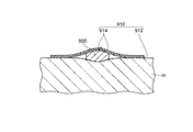
- FIG. 9 is a cross-sectional view for explaining a conventional home permanent magnet magnetic therapy device 900.
- a conventional home permanent magnet magnetic therapy device 900 is a disc-shaped home permanent magnet magnetic therapy device used by being attached to the surface of a user's skin H with a bandage 910, and is a ferrite magnet having a thickness of 2.5 mm and a diameter of 5 mm. Consists of.
- symbol 912 shows the base material of the adhesive bandage 910
- symbol 914 shows an upper release paper.
- the home permanent magnet magnetic therapy device 900 since the home permanent magnet magnetic therapy device 900 is made of a ferrite magnet having a weak magnetic force, it is somewhat necessary to secure a magnetic force required as a home permanent magnet magnetic therapy device. As a result, there is a problem that a feeling of wearing is impaired at the time of use. Further, in the conventional home permanent magnet magnetic therapy device 900, a ferrite magnet containing a metal component that has a high possibility of causing abnormalities such as skin (for example, metal allergy) to the user is provided by the user. Since it comes into direct contact with the skin surface, there is a problem that there is a high possibility of causing an abnormality in the user's skin and the like.
- An object is to provide a magnetic therapy device.
- the home permanent magnet magnetic treatment device of the present invention is a home use permanent magnet magnetic treatment device that is used by being attached to the skin surface of the user with an attaching member, and stores the permanent magnet portion having a columnar internal space.
- a protective case portion having a thickness of 0.5 mm to 2.2 mm and a permanent magnet portion storage portion and having a thickness of 0.3 mm to 1.2 mm.
- a permanent magnet portion made of a columnar neodymium-iron-boron alloy sintered magnet, and the length of the permanent magnet portion along the thickness direction of the protective case portion is in the thickness direction of the protective case portion.
- the permanent magnet portion is shorter than the length of the inner space along the inner space, and the permanent magnet portion is movable along the “direction perpendicular to the thickness direction of the protective case portion” in the inner space. , Stored in the permanent magnet section storage section.
- the thickness of the protective case portion is in the range of 0.5 mm to 2.2 mm, it is thinner and used than the conventional home permanent magnet magnetic therapy device. Sometimes it does not impair the fit.
- the thickness of the protective case portion falls within the range of 0.5 mm to 2.2 mm, the thickness of the permanent magnet portion is also reduced to 0.3 mm to 1.2 mm. Since it is composed of a neodymium-iron-boron alloy sintered magnet having a strong magnetic force, a sufficient magnetic therapeutic effect can be obtained.
- the household permanent magnet magnetic treatment device of the present invention since the permanent magnet part is housed in the permanent magnet part housing part inside the protective case part, the permanent magnet part is placed on the skin surface of the user during use. The direct contact is eliminated, and the surface of the protective case portion is made of a material having low reactivity to the human body, thereby reducing the possibility of causing an abnormality in the user's skin or the like.
- the home permanent magnet magnetic treatment device of the present invention is a home permanent magnet magnetic treatment device that does not impair the wearing feeling at the time of use and has a low possibility of causing an abnormality in the user's skin or the like. .
- the protective case portion protects the permanent magnet portion whose strength may be impaired by setting the thickness within the range of 0.3 mm to 1.2 mm. It becomes possible to make a household permanent magnet magnetic therapy device having sufficient strength.
- the permanent magnet portion is in a state movable along the “direction orthogonal to the thickness direction of the protective case portion”, and the permanent magnet portion storage portion. Therefore, when the user moves, the permanent magnet portion moves accordingly, and as a result, an appropriate magnetic therapy effect can be obtained over the entire range in which the permanent magnet moves.
- the distance from the human body to the permanent magnet portion does not vary, it is possible to always obtain a predetermined magnetic therapy effect.
- the movement of the permanent magnet according to the movement of the user is usually irregular, the magnetic force acting on the human body also changes irregularly, resulting in a more effective magnetic therapy effect (for example, a further blood circulation promoting effect) can be obtained.
- the thickness of the protective case part is 1.5 mm or less from the viewpoint of not impairing the wearing feeling during use.
- the thickness of the protective case part is more preferably 0.8 mm or more from the viewpoint of ensuring strength.
- the thickness of the permanent magnet part is more preferably 1 mm or less from the viewpoint of storage in the protective case part.
- the thickness of the permanent magnet portion is more preferably 0.4 mm or more from the viewpoint of securing a sufficient magnetic force.
- the length of the permanent magnet portion along the thickness direction of the protective case portion is adjusted so that the permanent magnet portion can be moved more smoothly in the permanent magnet storage portion. More preferably, it is shorter than the length of the space by 0.05 mm or more. In addition, the length of the internal space along the thickness direction of the protective case part is preferably in the range of 0.35 mm to 1.5 mm.
- a rust prevention layer is formed on the surface of the permanent magnet portion.
- the rust preventive layer refers to a layer having an effect of preventing corrosion of the permanent magnet portion.
- a rust preventive layer made of nickel, a rust preventive layer made of various resins, a rust preventive layer made of a noble metal, or the like can be used as the rust preventive layer.
- the area of the permanent magnet portion storage portion is the area of the permanent magnet portion. It is preferable that it is 1.2 times or more.
- the permanent magnet portion moves dynamically in the internal space, so that a larger magnetic treatment effect can be obtained.
- the area of the permanent magnet part storage part is more preferably 1.5 times or more, more preferably 2 times or more the area of the permanent magnet part.
- the home permanent magnet magnetic therapy device has a cylindrical shape
- the internal space has a cylindrical shape
- the permanent magnet portion is a cylindrical shape.
- the inner space has a diameter in the range of 3.0 mm to 15.0 mm
- the permanent magnet portion has an outer diameter in the range of 1.0 mm to 13.7 mm.
- the area of the permanent magnet part storage part can be made sufficiently larger than the area of the permanent magnet part when viewed along the axial direction of the home permanent magnet magnetic therapy device.
- the permanent magnet portion has anisotropy in the thickness direction.
- the permanent magnet portion 10 having a strong magnetic force is obtained.
- the protective case portion is positioned on the skin surface side of the user when in use, and the skin surface side of the user when in use.
- a second case member that is positioned on the opposite side of the permanent magnet portion, and the permanent magnet portion storage portion is formed by an inner surface of the first case member and an inner surface of the second case member. preferable.
- the permanent magnet portion is housed in the permanent magnet portion housing portion formed by the inner surface of the first case member and the inner surface of the second case member, it can be used to prevent corrosion of the permanent magnet portion from outside air, sweat, etc. It becomes possible to protect the permanent magnet portion.
- both the first case member and the second case member are made of a nonmagnetic metal material.
- a protective case part is a metal material (nonmagnetic metal material), it becomes possible to set it as a highly rigid protective case part.
- the protective case part is made of a nonmagnetic metal material, the movement of the permanent magnet part in the internal space is not suppressed.
- the first case member that is positioned on the skin surface side of the user at the time of use is made of a nonmagnetic metal material, the magnetic therapy effect is impaired. It will never happen.
- a non-magnetic metal material refers to a metal material that does not have magnetism.
- Specific examples of nonmagnetic metal materials include copper, copper alloys, titanium, titanium alloys, aluminum, aluminum alloys, magnesium, magnesium alloys, zinc, zinc alloys, nonmagnetic steel, noble metals, and alloys based on noble metals. be able to.
- the first case member which will be located on the skin surface side of the user when in use, is made of titanium, titanium alloy, some nonmagnetic steel (particularly austenitic stainless steel), noble metal or an alloy containing noble metal as a main component.
- the nonmagnetic metal material since the nonmagnetic metal material has a very low reactivity to the human body, it can be used as a home permanent magnet magnetic therapy device that is extremely unlikely to cause an abnormality on the user's skin.
- the first case member is made of aluminum, an aluminum alloy, magnesium, or a magnesium alloy
- the reactivity with respect to the human body can be made extremely low by performing anodizing treatment or chemical conversion treatment. It is possible to provide a home-use permanent magnet magnetic therapy device that is extremely unlikely to cause abnormalities.
- the first case member is made of copper, copper alloy, zinc, zinc alloy and many nonmagnetic steels (particularly, high manganese steel and high nickel steel)
- the outer surface of the first case member is reactive to the human body. By forming a layer made of an extremely low material, the reactivity to the human body can be made extremely low, so that the permanent magnet magnetic therapy device for home use is extremely unlikely to cause abnormalities on the user's skin, etc. be able to.
- the copper alloy refers to an alloy containing copper as a main component and containing other components such as zinc, nickel, and tin. Specific examples include brass, white and bronze.
- the titanium alloy refers to an alloy containing titanium as a main component and containing other components such as aluminum, vanadium, niobium, silver, and molybdenum. Specific examples include 60 and 61 kinds of titanium alloys.
- the aluminum alloy refers to an alloy containing aluminum as a main component and containing zinc, magnesium, copper and other components. Specific examples include duralumin, 3000 series aluminum alloys and 4000 series aluminum alloys.
- the magnesium alloy is an alloy containing magnesium as a main component and containing aluminum, zinc, calcium and other components.
- a zinc alloy means the alloy which has zinc as a main component and contains aluminum, copper, magnesium, and other components.
- Specific examples include ZDC1 alloy and ZDC2 alloy.
- Non-magnetic steel refers to steel that is not magnetic among those generally called steel.
- Specific examples include austenitic stainless steel, austenitic heat resistant steel, high manganese steel, and high nickel steel.
- the noble metal is a generic name for gold, silver and platinum group metals. Gold, silver, platinum, and palladium are particularly suitable as the material for the first case member.
- the alloys mainly composed of noble metals refer to various alloys mainly composed of the above-mentioned noble metals.
- the outer surface of the first case member and the outer surface of the second case member are both protective coating layers mainly composed of gold, platinum, rhodium or palladium. Is preferably formed.
- gold, platinum, rhodium or palladium is a non-magnetic metal and a metal with extremely low reactivity
- the above-described configuration can be applied to the skin of the user without impairing the magnetic treatment effect.
- the possibility of causing an abnormality can be extremely reduced.
- gold, platinum, rhodium or palladium is a noble metal having an excellent texture, it becomes a high-class home permanent magnet magnetic therapy device.
- the thickness of the protective coating layer is preferably 0.03 ⁇ m or more, and more preferably 0.1 ⁇ m or more from the viewpoint of securing the effect. Moreover, it is preferable that the said thickness is 3 micrometers or less from a viewpoint of ensuring difficulty in peeling.
- a base plating layer made of nickel, palladium, or a nickel-palladium alloy is provided between the first case member, the second case member, and the protective coating layer. Preferably it is formed.
- the thickness of the base plating layer is preferably 0.05 ⁇ m or more from the viewpoint of securing the effect. Moreover, it is preferable that the said thickness is 3 micrometers or less from a viewpoint of ensuring difficulty in peeling.
- a protective coating layer mainly composed of gold, platinum, rhodium or palladium is also formed on the inner surface of the first case member and the inner surface of the second case member.
- a base plating layer made of the same material is formed with substantially the same thickness as the base plating layer. It is preferable.
- the protective coating layer is also formed on the inner surface of the first case member and the inner surface of the second case member, and nickel is further interposed between the first case member and the second case member and the protective coating layer.
- the material of the base plating layer is a material having a magnetic property, so that the movement of the permanent magnet portion in the internal space of the protective case portion It is thought that this may be hindered.
- the base plating layer made of the same kind of material nickel or nickel-palladium alloy
- the base plating layer It has been confirmed that the movement of the permanent magnet part is not hindered in the internal space of the protective case part due to the formation of (see Embodiment 5 described later). The reason for this is not yet clearly understood, but it is presumed that this is because the base plating layer of the first case member, the base plating layer of the second case member, and the permanent magnet jointly constitute a magnetic circuit.
- the outer surface of the first case member and the outer surface of the second case member are surfaces exposed to the outside when used as a protective case portion.
- the inner surface of the first case member and the inner surface of the second case member refer to surfaces that face the permanent magnet portion when used as a protective case portion.
- the protective coating layer preferably contains germanium, radium or tourmaline.
- the surface of the household permanent magnet magnetic therapy device is subjected to sealing treatment by impregnation, dipping, spray coating, electrodeposition coating or baking coating. It is preferable.
- the home permanent magnet magnetic therapy device has higher safety and higher corrosion resistance. It becomes possible.
- the resin used for the sealing treatment include acrylic resin, epoxy resin, and phenol resin.
- both the first case member and the second case member are made of resin.
- the above configuration can extremely reduce the possibility of causing abnormalities in the skin of the user without impairing the magnetic treatment effect. it can.
- the resin is relatively easy to mold and process, it is possible to provide a protective case portion that is relatively easy to manufacture.
- the protective case part is made of a resin that is a nonmagnetic material, the movement of the permanent magnet part in the internal space is not suppressed.
- the protective case part preferably contains germanium, radium or tourmaline in the resin.
- the protective case portion further includes a seal member sandwiched between the first case member and the second case member.
- the seal member refers to a member that fills a gap between the first case member and the second case member. Specific examples include an O-ring, a sheet, and an adhesive. As a material constituting the seal member, a resin, rubber, or the like having high durability against the outside air, sweat, or the like can be suitably used.
- the corner portion of the protective case portion is rounded, chamfered, or both.
- Such a configuration makes it possible to improve the wearing feeling and safety during use.
- FIG. 3 is a flowchart illustrating a method for manufacturing the permanent magnet unit 10 in the home permanent magnet magnetic therapy device 100 according to the first embodiment. It is sectional drawing shown in order to demonstrate the domestic permanent magnet magnetic therapy device 102 concerning Embodiment 2. FIG. It is a figure shown in order to demonstrate the domestic permanent magnet magnetic therapy device 104 concerning Embodiment 3. FIG. It is a figure shown in order to demonstrate the domestic permanent magnet magnetic therapy device 106 concerning Embodiment 4.
- FIG. 1 It is a figure shown in order to demonstrate the domestic permanent magnet magnetic therapy device 108 concerning Embodiment 5.
- FIG. It is a figure shown in order to demonstrate the domestic permanent magnet magnetic therapy device 200 concerning Embodiment 6.
- FIG. It is sectional drawing shown in order to demonstrate the conventional household permanent magnet magnetic therapy device 900.
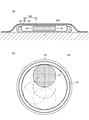
- FIG. 1 is a view for explaining a usage mode of the home permanent magnet magnetic therapy device 100 according to the first embodiment.
- FIG. 1A is a longitudinal sectional view showing a usage mode of a home permanent magnet magnetic therapy device 100
- FIG. 1B is a diagram of the home permanent magnet magnetic therapy device 100 as viewed from the first case member 40 side. It is. However, illustration of the 1st case member 40 is abbreviate
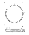
- FIG. 2 is a view for explaining the home permanent magnet magnetic therapy device 100 according to the first embodiment.
- 2A is a top view showing the home permanent magnet magnetic therapy device 100
- FIG. 2B is a cross-sectional view taken along the line A1-A1 of FIG. 2A.
- the arrows schematically show the movement of the permanent magnet.
- the symbol t1 indicates the thickness of the protective case portion 20
- the symbol t2 indicates the thickness of the permanent magnet portion 10 (the length of the permanent magnet portion 10 along the thickness direction of the protective case portion 20).
- the symbol t3 indicates the length of the internal space 50 along the thickness direction of the protective case portion 20.
- the home permanent magnet magnetic therapy device 100 When using the home permanent magnet magnetic therapy device 100 according to the first embodiment, as shown in FIG. 1, the home permanent magnet magnetic therapy device 100 is attached to the surface of the user's skin H with a bandage 500.
- the adhesive bandage 500 includes a base material and an adhesive layer.
- the base material for example, a cotton-polyurethane blend material, polyvinyl chloride, paper-based nonwoven fabric, and the like can be suitably used.
- the material for the adhesive layer for example, an acrylic adhesive material, a rubber adhesive material, a silicone adhesive material, or the like can be suitably used.
- the household permanent magnet magnetic therapy device 100 includes a disk-shaped (or columnar) protective case unit 20 and a disk-shaped (or columnar) permanent magnet unit. 10.
- the protective case part 20 has a permanent magnet part storage part 50 having a columnar inner space S, and has a thickness t1 of 1.4 mm and an outer diameter of 10 mm.
- the protective case portion 20 is made of titanium, which is a nonmagnetic metal material, and is located on the skin surface side of the user when used, and the protective case portion 20 is made of titanium, which is a nonmagnetic metal material, and is used by the user when used. It has the 2nd case member 40 which will be located in the opposite side to the skin surface side.
- the inner surface of the first case member 30 and the inner surface of the second case member 40 form a disk-shaped (columnar) permanent magnet portion storage portion 50.
- the thickness of the surface (bottom surface) of the first case member 30 facing the skin H surface side of the user of the permanent magnet unit 10 during use is 0.2 mm.
- the thickness of the surface (top surface) of the second case member 40 facing the surface of the permanent magnet unit 10 opposite to the user's skin H surface side during use is also 0.2 mm. Therefore, the length of the internal space S along the thickness direction of the protective case portion 20 is 1.0 mm.
- the inner diameter of the permanent magnet unit storage unit 50 is 8.2 mm.
- the permanent magnet section 10 is housed in the permanent magnet section housing section 50 and is formed of a cylindrical neodymium-iron-boron alloy sintered magnet having a diameter of 4.0 mm and a thickness of 0.8 mm.
- the length t3 of the permanent magnet portion along the thickness direction of the protective case portion 20 (the thickness of the permanent magnet portion 10) is greater than the length t2 of the internal space S along the thickness direction of the protective case portion 20.
- the permanent magnet unit 10 is stored in the permanent magnet unit storage unit 50 in a state in which the permanent magnet unit 10 is movable along the “direction orthogonal to the thickness direction of the protective case unit 20” in the internal space S. Has been.
- the area of the permanent magnet unit storage unit 50 is the area of the permanent magnet magnetic unit. Is about 4 times.
- the first case member 30 and the second case member 40 are fixed by fitting.
- this invention is not restricted to this, A 1st case member and a 2nd case member can also be fixed with a latch structure, an adhesive agent, etc.
- the corner portion of the protective case portion 20 is both rounded and chamfered.
- a rust prevention layer made of nickel is formed on the surface of the permanent magnet portion 10.
- the rust prevention layer is formed by an electrolytic plating method as will be described later.
- the permanent magnet unit 10 is configured so that the magnetic flux density on the surface side of the user's skin H is about 180 mT when the home permanent magnet magnetic therapy device 100 is used.
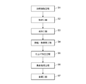
- FIG. 3 is a flowchart showing a method of manufacturing the permanent magnet unit 10 in the home permanent magnet magnetic therapy device 100 according to the first embodiment.
- the permanent magnet portion 10 is composed of a neodymium-iron-boron alloy sintered magnet as described above, and a method for producing the neodymium-iron-boron alloy sintered magnet will be described below.
- Heat melting step S1 First, the raw materials (neodymium, iron, boron, and other additives) of the permanent magnet part 10 are mixed and then melted at a temperature of 1200 ° C. to 1300 ° C.
- a high frequency melting furnace can be used for the heating.
- the heating and melting step S1 is performed under an inert gas (for example, argon gas) atmosphere or under vacuum in order to prevent oxidation of the raw material.
- Molding step S3 Next, the raw material in powder form is put into a mold corresponding to the shape of the permanent magnet portion 10 and press molding is performed. At this time, by applying a magnetic field along the direction to be magnetized in the magnetizing step S7 and performing press molding as it is, the directions of the crystal components constituting the magnet can be aligned. Thereby, the completed permanent magnet part 10 can be made into a strong permanent magnet.
- the molding step S3 is preferably performed in an inert gas (for example, nitrogen gas) atmosphere in order to prevent oxidation of the raw material.
- the finishing process S5 is a process for aligning the dimensions of the sintered and heat-treated members and smoothing the surface.
- the dimensions of the members can be aligned using, for example, a grinding machine equipped with a diamond grindstone.
- the smoothing of the surface can be performed using various barrel polishing machines such as a rotary type, a centrifugal type, and a swing type.
- a surface treatment for enhancing the corrosion resistance is performed on the finished member to form a rust prevention layer.
- the rust preventive layer is a nickel layer formed by an electrolytic plating method.
- Magnetization process S7 Finally, a magnetic field is generated by a pulse magnetizer or the like, and magnetization is performed in the magnetic field to complete the permanent magnet unit 10.
- the strength of the generated magnetic field is, for example, about 30 kOe.
- the permanent magnet unit 10 can be manufactured by such a method.
- the raw material bar which consists of titanium is prepared.
- the raw bar is processed into a raw member having a size and shape corresponding to the first case member 30.
- the processing can be performed, for example, by cutting, grinding, or both.
- a machine for performing cutting for example, a cam type lathe, an NC lathe, or the like can be used.
- a surface grinder, a cylindrical grinder, etc. can be used, for example.
- the surface of the original member is smoothed and rounded to form the first case portion 30.
- the smoothing and rounding of the surface can be performed using various barrel polishing machines such as a rotary type, a centrifugal type, and a swing type. By such a method, the first case member 30 can be manufactured.
- the manufacturing method of the second case member 40 is basically the same as the manufacturing method of the first case member 30 except that the size and shape correspond to the second case member 40. The same as above. Therefore, the description about the manufacturing method of the 2nd case member 40 is abbreviate
- the first case member 30 and the second case member 40 can be manufactured by such a method.
- the permanent magnet unit 10 is disposed inside the first case member 30.
- the fitting locations in both the first case member 30 and the second case member 40 are matched.
- pressure is applied to fit the first case member 30 and the second case member 40 together.
- the pressure can be applied by machine or human power.
- the home permanent magnet magnetic therapy device 100 can be assembled.
- the home permanent magnet magnetic therapy device 100 is manufactured by the manufacturing method of the permanent magnet portion 10, the manufacturing method of the first case member 30 and the second case member 40, and the assembly method of the home permanent magnet magnetic therapy device 100. be able to.
- the thickness t1 of the protective case portion 20 is in the range of 0.5 mm to 2.2 mm (1.4 mm). It is thinner than the magnet magnetic therapy device 900 and does not impair the wearing feeling during use.
- the thickness t1 of the protective case portion 20 is set within the range of 0.5 mm to 2.2 mm (1.4 mm)
- the thickness t2 of the permanent magnet portion 10 is also 0.3 mm to 1.2 mm (
- the permanent magnet portion 10 is made of a neodymium-iron-boron alloy sintered magnet having a strong magnetic force, a sufficient magnetic treatment effect can be obtained.
- the permanent magnet unit 10 is stored in the permanent magnet unit storage unit 50 inside the protective case unit 20, so that the permanent magnet unit 10 is used during use. Is not in direct contact with the surface of the user's skin H, and the surface of the protective case portion 20 is made of a material having low reactivity to the human body, thereby reducing the possibility of causing an abnormality in the user's skin or the like. It becomes possible.
- the surface of the protective case portion 20 is made of titanium that has extremely low reactivity to the human body. As a result, the home permanent magnet magnetic therapy device 100 according to the first embodiment does not impair the wearing feeling during use, and has a low possibility of causing an abnormality in the user's skin and the like. It becomes a vessel.
- the permanent magnet portion 10 whose strength may be impaired by setting the thickness to 0.3 mm to 1.2 mm (0.8 mm). It becomes possible to provide a home permanent magnet magnetic therapy device that is protected by the protective case portion 20 and has sufficient strength.
- the permanent magnet unit 10 is at least movable along the “direction orthogonal to the thickness direction of the protective case unit 20”. Since it is accommodated in the part accommodating part 50, if a user moves, the permanent magnet part 10 will move according to it, As a result, it will become possible to acquire an appropriate magnetic treatment effect over the whole range which the permanent magnet 10 moves. Further, since the distance from the human body to the permanent magnet unit 10 does not vary, it is possible to always obtain a predetermined magnetic therapy effect.
- the magnetic force acting on the human body also changes irregularly, and as a result, a more effective magnetic therapy effect (For example, a further blood circulation promoting effect) can be obtained.
- the area of the permanent magnet unit storage unit 50 is the permanent magnet unit when viewed along the axial direction of the household permanent magnet magnetic therapy device 100. Since the area of 10 is 1.2 times or more (4 times), the permanent magnet portion moves dynamically in the internal space, so that a larger magnetic treatment effect can be obtained.
- the home permanent magnet magnetic therapy device 100 has a cylindrical shape
- the internal space S has a cylindrical shape
- the permanent magnet portion 10 has a cylindrical shape.
- the inner space S has an inner diameter in the range of 3.0 mm to 15.0 mm (8.2 mm)
- the permanent magnet portion has an outer diameter of 1.0 mm to 13.7 mm (4.0 mm). Therefore, when viewed along the axial direction of the home-use permanent magnet magnetic therapy device 100, the area of the permanent magnet portion storage portion 50 can be made sufficiently larger than the area of the permanent magnet portion 10.
- the permanent magnet portion 10 has anisotropy in the thickness direction, and thus becomes a permanent magnet portion having a strong magnetic force.
- the protective case portion 20 is positioned on the surface side of the user's skin H when in use, and the user when in use.
- a second case member 40 that is located on the opposite side of the skin H surface side, and the permanent magnet portion storage portion 50 is formed by the inner surface of the first case member 30 and the inner surface of the second case member 40. Since it is formed, it becomes a household permanent magnet magnetic therapy device which can store a permanent magnet part in a permanent magnet part storage part.
- the protective case portion has high rigidity. It becomes possible.
- the protective case portion 20 is made of a nonmagnetic metal material (titanium)
- the movement of the permanent magnet portion in the internal space is suppressed.
- the first case member 30 that is positioned on the skin surface side of the user when used is made of a nonmagnetic metal material (titanium). Therefore, the magnetic therapy effect is not impaired.
- the first case member 30 is made of titanium that is extremely low in reactivity to the human body, it can be a home permanent magnet magnetic therapy device that is extremely unlikely to cause an abnormality on the skin of the user.
- the corner portion of the protective case portion 20 is subjected to both rounding and chamfering processing, so that the wearing feeling and safety during use are safe. It becomes possible to improve the property.
- the domestic permanent magnet magnetic treatment device 100 since the rust prevention layer made of nickel plating is formed on the surface of the permanent magnet portion 10, the corrosion resistance of the permanent magnet portion 10 is improved. Is possible.
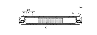
- FIG. 4 is a cross-sectional view for explaining the home permanent magnet magnetic therapy device 102 according to the second embodiment.
- the home permanent magnet magnetic therapy device 102 according to the second embodiment basically has the same configuration as the home permanent magnet magnetic therapy device 100 according to the first embodiment, but the configuration of the protective case portion is different. That is, in the household permanent magnet magnetic therapy device 102 according to the second embodiment, as shown in FIG. 4, the protective case portion 22 is a seal member that is sandwiched between the first case member 32 and the second case member 42. 60. Accordingly, the configurations of the first case member 32 and the second case member 42 in the home permanent magnet magnetic therapy device 100 according to the first embodiment are the same as the configurations of the first case member 30 and the second case member 40 according to the first embodiment. The first case member 32 and the second case member 42 are fixed by a latch structure.
- the seal member 60 is an O-ring made of butyl rubber.
- the home permanent magnet magnetic therapy device 102 according to the second embodiment differs from the home permanent magnet magnetic therapy device 100 according to the first embodiment in the configuration of the protective case part, but the home permanent magnet magnetic treatment device 102 according to the first embodiment is different from the home permanent magnet magnetic therapy device 100 according to the first embodiment.
- the thickness of the protective case portion 22 is 1.4 mm
- the permanent magnet portion 10 is accommodated in the permanent magnet portion accommodating portion 52 inside the protective case portion 22.
- the permanent magnet unit 10 is stored in the permanent magnet unit storage unit 52 in a state in which the permanent magnet unit 10 can move along the “direction perpendicular to the thickness direction of the protective case unit 22” in the internal space S.
- the wearing feeling is not impaired during use, and the possibility of causing an abnormality in the user's skin etc. is low.
- the permanent magnet part moves accordingly, and as a result, the permanent magnet Over the entire range of movement To Te obtain an appropriate magnetic therapeutic effects is home permanent magnet magnet therapy possible.
- the protective case portion 22 further includes the seal member 60 sandwiched between the first case member 32 and the second case member 42.
- the action of the seal member 60 makes it possible to prevent the outside air, sweat, and the like from entering the inside of the protective case portion 22, and to protect the permanent magnet portion 10 more reliably.
- the home permanent magnet magnetic therapy device 102 according to the second embodiment has the same configuration as that of the home permanent magnet magnetic therapy device 100 according to the first embodiment except for the configuration of the protective case portion. It has the pertinent effect among the effects which the permanent magnet magnetic therapy device 100 for homes concerning the form 1 has.
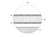
- FIG. 5 is a view for explaining the home permanent magnet magnetic therapy device 104 according to the third embodiment.
- FIG. 5A is a cross-sectional view of the home permanent magnet magnetic therapy device 104
- FIG. 5B is a partially enlarged cross-sectional view that enlarges and displays the range indicated by the symbol R1 in FIG. 5A.
- the thickness of the protective coating layer 70 is exaggerated.
- the home permanent magnet magnetic therapy device 104 according to the third embodiment basically has the same configuration as that of the home permanent magnet magnetic therapy device 100 according to the first embodiment, but includes the first case member and the second case member.
- the configuration is different. That is, in the household permanent magnet magnetic therapy device 104 according to the third embodiment, as shown in FIG. 5, the first case member 34 and the second case member 44 are made of brass, and the outer surface of the first case member 34 A protective coating layer 70 made of gold is formed on the outer surface of the second case member 44.
- the thickness of the protective coating layer 70 is 2 ⁇ m, and can be formed by, for example, an electrolytic plating method or an electroless plating method.
- the home permanent magnet magnetic therapy device 104 according to the third embodiment is different from the home permanent magnet magnetic therapy device 100 according to the first embodiment in the configuration of the first case member and the second case member.
- the thickness of the protective case portion 24 is 1.4 mm
- the permanent magnet portion 10 is housed in the permanent magnet portion inside the protective case portion 24.
- the permanent magnet unit 10 is accommodated in a state in which the permanent magnet unit 10 is movable in the internal space S along the “direction perpendicular to the thickness direction of the protective case unit 24”. Since it is housed in the part 54, the wearing feeling is not impaired during use, and the possibility of causing an abnormality in the user's skin is low. Furthermore, when the user moves, the permanent magnet part moves accordingly. As a result, permanent magnet To obtain an appropriate magnetic therapeutic effect over the entire range of motion becomes capable home permanent magnet magnet therapy.
- the protective coating layer 70 made of gold is formed on the outer surface of the first case member 34 and the outer surface of the second case member 44.
- the possibility of causing an abnormality in the user's skin or the like can be made extremely low without impairing the magnetic treatment effect. Further, it is possible to protect both the first case member 34 and the second case member 44 from outside air, sweat, etc., and to improve the corrosion resistance.
- gold is a precious metal with an excellent texture, it becomes a high-class home permanent magnet magnetic therapy device.
- the home permanent magnet magnetic therapy device 104 according to the third embodiment is the same as the home permanent magnet magnetic therapy device 100 according to the first embodiment except for the configuration of the first case member and the second case member. Since it has a structure, it has the applicable effect as it is among the effects which the home permanent magnet magnetic therapy device 100 according to the first embodiment has.
- FIG. 6 is a view for explaining the home permanent magnet magnetic therapy device according to the fourth embodiment.
- FIG. 6 is a diagram corresponding to FIG. In FIG. 6, the thickness of the protective coating layer 70 is exaggerated.
- the home permanent magnet magnetic therapy device basically has the same configuration as that of the home permanent magnet magnetic therapy device 104 according to the third embodiment, but the configuration of the protective coating layer is different. That is, in the household permanent magnet magnetic therapy device 106 according to the fourth embodiment, as shown in FIG. 6, the protective coating layer 70 made of gold is formed on the inner surface of the first case member and the inner surface of the second case member 46 (not shown). Also formed.
- the thickness of the protective coating layer 70 is 2 ⁇ m, and can be formed by, for example, an electrolytic plating method or an electroless plating method.
- the home permanent magnet magnetic therapy device is different from the home permanent magnet magnetic therapy device 104 according to the third embodiment in the configuration of the first case member and the second case member, but the embodiment
- the thickness of the protective case portion is 1.4 mm
- the permanent magnet portion 10 is accommodated in the permanent magnet portion accommodating portion inside the protective case portion.
- the permanent magnet portion 10 is accommodated in the permanent magnet portion accommodating portion so as to be movable along the “direction perpendicular to the thickness direction of the protective case portion” in the internal space S. Therefore, the wearing feeling is not impaired at the time of use, the possibility of causing an abnormality in the user's skin, etc. is low, and when the user moves, the permanent magnet part moves accordingly. Appropriate over the entire moving range Obtaining a care therapeutic effect is home permanent magnet magnet therapy possible.
- the protective coating layer 70 made of gold is also formed on the inner surface of the first case member and the inner surface of the second case member 46. The reliability of the permanent magnet magnetic therapy device can be further increased.
- the home permanent magnet magnetic therapy device according to the fourth embodiment has the same configuration as that of the home permanent magnet magnetic therapy device 104 according to the third embodiment except for the configuration of the protective coating layer. 3 has the corresponding effect as it is among the effects of the home permanent magnet magnetic therapy device 104 according to No. 3.
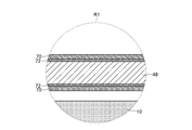
- FIG. 7 is a view for explaining the home permanent magnet magnetic therapy device according to the fifth embodiment.
- FIG. 7 is a diagram corresponding to FIG. In FIG. 7, the thicknesses of the protective coating layer 70 and the base plating layer 72 are exaggerated.
- the home permanent magnet magnetic therapy device basically has the same configuration as that of the home permanent magnet magnetic therapy device according to the fourth embodiment, but the configuration of the protective coating layer is different. That is, in the home permanent magnet magnetic therapy device according to the fifth embodiment, as shown in FIG. 7, a protective coating layer 70 made of gold is not shown through a base plating layer 72 made of nickel. And the surface of the second case member 48.
- the thickness of the protective coating layer 70 is 2 ⁇ m, and can be formed by, for example, an electrolytic plating method or an electroless plating method.
- the thickness of the base plating layer 72 is 0.5 ⁇ m, and can be formed by, for example, an electrolytic plating method or an electroless plating method.
- the home permanent magnet magnetic therapy device is different from the home permanent magnet magnetic therapy device according to the fourth embodiment in the configuration of the protective coating layer, but the home permanent magnet according to the fourth embodiment.
- the thickness of the protective case portion (not shown) is 1.4 mm
- the permanent magnet portion 10 is accommodated in the permanent magnet portion accommodating portion inside the protective case portion, and further, Since the magnet part 10 is housed in the permanent magnet part housing part in a state in which it can move along the “direction perpendicular to the thickness direction of the protective case part” in the internal space S, it feels comfortable to wear during use.
- the protective coating layer 70 made of gold is disposed on the surface of the first case member and the second case member 48 through the base plating layer 72 made of nickel. Therefore, it is possible to improve the adhesion, the denseness, the plating coverage and the stability of the protective coating layer, and to further improve the corrosion resistance of the protective coating layer.
- the magnetic material nickel is used between the inner surface of the first case member, the inner surface of the second case member, and the protective coating layer 70 made of gold. Since the underlying plating layer 72 to be formed is formed, it is considered that the movement of the permanent magnet portion may be hindered in the internal space of the protective case portion.
- a base plating layer made of the same kind of material for example, nickel
- the movement of the permanent magnet part was not hindered in the internal space of the protective case part due to the formation of the base plating layer.
- the home permanent magnet magnetic therapy device according to Embodiment 5 has the same configuration as that of the home permanent magnet magnetic therapy device according to Embodiment 4 except for the configuration of the protective coating layer. It has the corresponding effect as it is among the effects of the home permanent magnet magnetic therapy device.
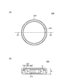
- FIG. 8 is a view for explaining the home permanent magnet magnetic therapy device 200 according to the sixth embodiment.
- FIG. 8A is a top view showing the home permanent magnet magnetic therapy device 200
- FIG. 8B is a cross-sectional view taken along line A2-A2 of FIG. 8A.
- the symbol t1 indicates the thickness of the protective case portion 220
- the symbol t2 indicates the thickness of the permanent magnet portion 210 (the length of the permanent magnet portion 210 along the thickness direction of the protective case portion 220).
- the symbol t3 indicates the length of the internal space S along the thickness direction of the protective case 220.
- the home permanent magnet magnetic therapy device 200 according to the sixth embodiment has basically the same configuration as the home permanent magnet magnetic therapy device 100 according to the first embodiment, but includes the first case member and the second case member.
- the material is different. That is, in the household permanent magnet magnetic therapy device 200 according to Embodiment 6, both the first case member 230 and the second case member 240 are made of polypropylene, which is a resin.
- the thickness of the protective case portion 220 is 2.0 mm
- the thickness of the bottom surface of the protective case portion 220 is 0.5 mm
- the thickness of the top surface of the protective case portion 220 is 0.5 mm.
- the length of the internal space S along the thickness direction of the case portion 220 is 1.0 mm.
- the outer diameter of the protective case part 220 is 6.7 mm.
- the thickness of the permanent magnet part 210 is 0.8 mm.
- the diameter of the internal space S is 5.5 mm.
- the outer diameter of the permanent magnet unit 210 is 2.7 mm.
- the home permanent magnet magnetic therapy device 200 according to the sixth embodiment is different from the home permanent magnet magnetic therapy device 100 according to the first embodiment although the materials of the first case member and the second case member are different.
- the thickness of the protective case part is in the range of 0.5 mm to 2.2 mm (2.0 mm), and the permanent magnet part 10 is housed in the permanent magnet part housing part inside the protective case part, Furthermore, since the permanent magnet portion 10 is housed in the permanent magnet portion housing portion in a state that is movable along the “direction perpendicular to the thickness direction of the protective case portion” in the internal space S, As in the case of the home permanent magnet magnetic therapy device 100 according to the first embodiment, the wearing feeling is not impaired during use, the possibility of causing an abnormality in the user's skin and the like is low, and the user moves. And correspondingly the permanent magnet part Can, as a result, the permanent magnet magnetic therapy device for home use capable of obtaining a proper magnetic therapeutic effect over the entire range of the permanent magnet is moved.
- the possibility of causing an abnormality in the user's skin or the like can be extremely reduced without impairing the magnetic therapy effect.
- the resin is relatively easy to mold and process, it is possible to provide a protective case portion that is relatively easy to manufacture.
- the protective case 220 is made of a resin that is a nonmagnetic material, the movement of the permanent magnet 10 in the internal space S is suppressed. There is nothing.
- the home permanent magnet magnetic therapy device 200 according to the sixth embodiment has the same configuration as that of the home permanent magnet magnetic therapy device 100 according to the first embodiment except for the material of the protective coating layer. Among the effects of the home-use permanent magnet magnetic therapy device 100 according to the above, the corresponding effect is maintained as it is.
- Example 1 is an example showing an example in which the magnetic flux density of the home permanent magnet magnetic therapy device of the present invention is measured.
- the magnetic flux density was measured using a 410 Gaussmeter manufactured by Lake Shore.
- Example 1 1000 household permanent magnet magnetic therapy devices according to Embodiment 5 were manufactured, and the magnetic flux density was measured for 10 randomly selected from among them. As a result, in the household permanent magnet magnetic therapy device according to Example 1, the average value of the magnetic flux density on the bottom surface of the first case member is 176.3 mT, and the magnetic flux density on the top surface of the second case member is The average value was 176.0 mT.
- the shapes and dimensions of the permanent magnet part, the protective case part, etc. in the above embodiments are merely examples, and the present invention is not limited thereto.
- the outer diameter of the protective case portion can be 4 mm, 6 mm, 8 mm, 10 mm, 12 mm, 14 mm, 16 mm, or the like.
- the thickness of the permanent magnet portion is 0.8 mm, but the present invention is not limited to this.
- the thickness of the permanent magnet portion may be in the range of 0.3 mm to 1.2 mm.
- the protective case portion has a thickness of 1.4 mm. In the sixth embodiment, the protective case portion has a thickness of 2.0 mm. It is not limited to this. The thickness of the protective case portion may be in the range of 0.5 mm to 2.2 mm.
- the length of the permanent magnet portion along the thickness direction of the protective case portion is less than the length of the internal space S along the thickness direction of the protective case portion.
- the present invention is not limited to this. What is necessary is just to be shorter than the length of the internal space S by 0.05 mm or more.
- the permanent magnet portion has a diameter of 4 mm.
- the outer diameter of the permanent magnet portion is 2.67 mm. It is not limited. The outer diameter of the permanent magnet portion may be in the range of 1.0 mm to 13.7 mm.
- the first case member and the second case member are made of titanium.
- the first case member and the second case member are made of brass.
- the first case member and the second case member are, for example, copper, titanium alloy, aluminum, aluminum alloy, magnesium, magnesium alloy, zinc, zinc alloy, non-magnetic steel, noble metal, an alloy mainly composed of noble metal, other than brass. You may consist of other nonmagnetic metal materials, such as a copper alloy.
- the rust prevention layer made of nickel is formed on the surface of the permanent magnet portion, but the present invention is not limited to this.
- a rust prevention layer made of various resins, a rust prevention layer made of a noble metal, or the like may be formed.
- both the rounding process and the chamfering process are performed on the corner of the protective case part, but the present invention is not limited to this.
- only a rounding process and a chamfering process may be performed. Even with this configuration, it is possible to improve the wearing feeling and safety during use.
- the seal member 60 is an O-ring made of butyl rubber, but the present invention is not limited to this.
- the seal member may be, for example, a sheet or adhesive made of resin or rubber, an O-ring made of resin, or the like.
- first case member 32 and the second case member 42 are fixed by the latch structure in the second embodiment, the present invention is not limited to this.
- it may be fixed by fitting or an adhesive.
- the protective coating layer is made of gold, but the present invention is not limited to this.
- it may be composed of platinum, rhodium or palladium.
- it may be made of an alloy or a mixture containing gold, platinum, rhodium or palladium as a main component.
- the protective coating layer is made only of gold, but the present invention is not limited to this.
- the protective coating layer may contain germanium, radium or tourmaline. By setting it as such a structure, in addition to a magnetic therapeutic effect, the effect which germanium, radium, or tourmaline has (for example, activation of metabolism, blood flow promotion, a thermal effect, etc.) can be acquired.
- a protective coating layer is formed by composite plating in which germanium fine particles, radium fine particles or tourmaline fine particles are contained in a plating mainly composed of gold, platinum, rhodium or palladium. Can be configured. With such a configuration, it is possible to easily form a protective coating layer containing the fine particles described above.
- composite plating means what co-deposited fine particles during plating, and is also called eutectoid plating.
- the protective coating layer can be formed by alloy plating composed of an alloy containing gold, platinum, rhodium or palladium as a main component and containing germanium. With such a configuration, a protective coating layer containing germanium can be easily formed.
- a device for enabling easy discrimination between the first case member and the second case member may be made.
- the color of the first case member and the color of the second case member may be made different, or a case where a convex portion or a concave portion is provided only in one of the first case member or the second case member may be exemplified. it can.
- the permanent magnet portion has a disc shape (columnar shape), but the present invention is not limited to this.
- it may be a columnar shape such as a hexagonal column or an octagonal column.
- the surface of the home permanent magnet magnetic therapy device may be subjected to sealing treatment by impregnation, dipping, spray coating, electrodeposition coating or baking coating.
- sealing treatment by impregnation, dipping, spray coating, electrodeposition coating or baking coating.
- the protective case 220 is made of polypropylene, but the present invention is not limited to this.
- any material may be used as long as it is made of a resin that is stable and has low reactivity to the human body.
- it may be made of ABS (acrylonitrile-butadiene-styrene) resin, polyvinyl chloride, or the like.
- the protective case may contain germanium, radium, or tourmaline in the resin.
- the protective case part can contain germanium, radium, or tourmaline in various forms such as fine particles, flakes, and granules.
- the manufacturing method of the permanent magnet part demonstrated in the said Embodiment 1 is an example, and the permanent magnet part used for the domestic permanent magnet magnetic therapy device of this invention is a permanent magnet part manufactured by this method. It is not limited.
- the manufacturing method of the first case member 30 and the second case member 40 described in the first embodiment is an example, and the first case member and the second case member used in the home permanent magnet magnetic therapy device of the present invention.
- the case member is not limited to the first case member and the second case member manufactured by this method.
- the method of assembling the home permanent magnet magnetic therapy device described in the first embodiment is an example, and the home permanent magnet magnetic therapy device of the present invention is a home permanent magnet magnetic therapy device assembled by this method. It is not limited to.
- the first case member 30 and the second case member 40 are manufactured from the original rod. It is not limited to.
- the first case member and the second case member can be manufactured from the original plate.
- the original plate can be processed by pressing in addition to cutting and grinding, and a hydraulic or mechanical pressing machine can be used as a machine for performing the pressing.
- the home permanent magnet magnetic therapy device is attached to the skin surface of the user with the adhesive bandage 500, but the present invention is not limited to this. It is good also as sticking on a user's skin surface with various sticking members, such as a patch and a seal.
Landscapes
- Health & Medical Sciences (AREA)
- Engineering & Computer Science (AREA)
- Biomedical Technology (AREA)
- Nuclear Medicine, Radiotherapy & Molecular Imaging (AREA)
- Radiology & Medical Imaging (AREA)
- Life Sciences & Earth Sciences (AREA)
- Animal Behavior & Ethology (AREA)
- General Health & Medical Sciences (AREA)
- Public Health (AREA)
- Veterinary Medicine (AREA)
- Magnetic Treatment Devices (AREA)
Applications Claiming Priority (2)
| Application Number | Priority Date | Filing Date | Title |
|---|---|---|---|
| JP2009-237817 | 2009-10-15 | ||
| JP2009237817A JP2011083394A (ja) | 2009-10-15 | 2009-10-15 | 家庭用永久磁石磁気治療器 |
Publications (1)
| Publication Number | Publication Date |
|---|---|
| WO2011046018A1 true WO2011046018A1 (ja) | 2011-04-21 |
Family
ID=43876071
Family Applications (1)
| Application Number | Title | Priority Date | Filing Date |
|---|---|---|---|
| PCT/JP2010/066854 Ceased WO2011046018A1 (ja) | 2009-10-15 | 2010-09-28 | 家庭用永久磁石磁気治療器 |
Country Status (2)
| Country | Link |
|---|---|
| JP (1) | JP2011083394A (enExample) |
| WO (1) | WO2011046018A1 (enExample) |
Cited By (4)
| Publication number | Priority date | Publication date | Assignee | Title |
|---|---|---|---|---|
| WO2013080144A1 (en) * | 2011-11-29 | 2013-06-06 | Flavio Forner | Orthopedic aid |
| US10034827B2 (en) | 2014-09-17 | 2018-07-31 | The Procter & Gamble Company | Skin care product and method of use |
| USD846751S1 (en) | 2017-08-23 | 2019-04-23 | The Procter And Gamble Company | Cosmetic skin care device |
| US10322270B2 (en) | 2014-09-17 | 2019-06-18 | The Procter & Gamble Company | Skin care applicator |
Families Citing this family (1)
| Publication number | Priority date | Publication date | Assignee | Title |
|---|---|---|---|---|
| JP6377015B2 (ja) * | 2015-04-30 | 2018-08-22 | ピップ株式会社 | 変動磁場磁気治療器 |
Citations (7)
| Publication number | Priority date | Publication date | Assignee | Title |
|---|---|---|---|---|
| JPS61203052U (enExample) * | 1985-06-11 | 1986-12-20 | ||
| JPS63111881A (ja) * | 1986-10-30 | 1988-05-17 | 住友精化株式会社 | 磁気治療器 |
| JPS63111160U (enExample) * | 1987-01-09 | 1988-07-16 | ||
| JPH04197272A (ja) * | 1990-11-28 | 1992-07-16 | Pitsupu Fujimoto Kk | 変動磁場磁気治療器 |
| JPH11206892A (ja) * | 1998-01-26 | 1999-08-03 | Furuta Kagaku Kenkyusho:Kk | 磁石を使用する治療器具 |
| JP2003325683A (ja) * | 2002-05-15 | 2003-11-18 | Tadashi Mochizai | 磁気健康器具 |
| JP2006288594A (ja) * | 2005-04-08 | 2006-10-26 | Eintesla Inc | 健康促進具 |
-
2009
- 2009-10-15 JP JP2009237817A patent/JP2011083394A/ja active Pending
-
2010
- 2010-09-28 WO PCT/JP2010/066854 patent/WO2011046018A1/ja not_active Ceased
Patent Citations (7)
| Publication number | Priority date | Publication date | Assignee | Title |
|---|---|---|---|---|
| JPS61203052U (enExample) * | 1985-06-11 | 1986-12-20 | ||
| JPS63111881A (ja) * | 1986-10-30 | 1988-05-17 | 住友精化株式会社 | 磁気治療器 |
| JPS63111160U (enExample) * | 1987-01-09 | 1988-07-16 | ||
| JPH04197272A (ja) * | 1990-11-28 | 1992-07-16 | Pitsupu Fujimoto Kk | 変動磁場磁気治療器 |
| JPH11206892A (ja) * | 1998-01-26 | 1999-08-03 | Furuta Kagaku Kenkyusho:Kk | 磁石を使用する治療器具 |
| JP2003325683A (ja) * | 2002-05-15 | 2003-11-18 | Tadashi Mochizai | 磁気健康器具 |
| JP2006288594A (ja) * | 2005-04-08 | 2006-10-26 | Eintesla Inc | 健康促進具 |
Cited By (5)
| Publication number | Priority date | Publication date | Assignee | Title |
|---|---|---|---|---|
| WO2013080144A1 (en) * | 2011-11-29 | 2013-06-06 | Flavio Forner | Orthopedic aid |
| US10034827B2 (en) | 2014-09-17 | 2018-07-31 | The Procter & Gamble Company | Skin care product and method of use |
| US10058495B2 (en) | 2014-09-17 | 2018-08-28 | The Procter & Gamble Company | Method of making a skin care product |
| US10322270B2 (en) | 2014-09-17 | 2019-06-18 | The Procter & Gamble Company | Skin care applicator |
| USD846751S1 (en) | 2017-08-23 | 2019-04-23 | The Procter And Gamble Company | Cosmetic skin care device |
Also Published As
| Publication number | Publication date |
|---|---|
| JP2011083394A (ja) | 2011-04-28 |
Similar Documents
| Publication | Publication Date | Title |
|---|---|---|
| WO2011046018A1 (ja) | 家庭用永久磁石磁気治療器 | |
| JP5267459B2 (ja) | R−tm−b系ラジアル異方性リング磁石、その製造方法、及びそれを製造するための金型、並びにブラシレスモータ用ロータ | |
| JP5212602B2 (ja) | 機器およびハウジング材の製造方法 | |
| EP2562771B1 (en) | Method of manufacturing a dust core | |
| EP2647470A1 (en) | Super hard alloy baseplate outer circumference cutting blade and manufacturing method thereof | |
| EP2260963A1 (en) | Method and jig assembly for manufacturing outer blade cutting wheel | |
| CN102862129B (zh) | 硬质合金基部外部刀刃切割轮以及制造方法 | |
| EP2647469A1 (en) | Super hard alloy baseplate outer circumference cutting blade and manufacturing method thereof | |
| JP4978665B2 (ja) | 金属磁石及びそれを用いたモータ | |
| KR20090073019A (ko) | 외주 절단날 및 그의 제조 방법 | |
| JP5447898B2 (ja) | ハウジングおよび機器 | |
| JPWO1998031497A1 (ja) | 希土類磁石と金属材料の一体接合構造物及びその接合方法 | |
| JP2003507574A5 (enExample) | ||
| JP5098390B2 (ja) | 希土類磁石 | |
| CN103151130A (zh) | 磁性部件用粉末、粉末成形体及磁性部件 | |
| TW201229282A (en) | Ferromagnetic material sputtering target | |
| JP2015155143A (ja) | 超硬合金台板外周切断刃の製造方法 | |
| JP2011192910A (ja) | 希土類焼結磁石、回転機及び往復動モータ | |
| WO2023157663A1 (ja) | 磁石式義歯アタッチメント | |
| JP2011004786A (ja) | 家庭用永久磁石磁気治療器 | |
| JP2011004785A (ja) | 家庭用永久磁石磁気治療器 | |
| WO2004098024A1 (ja) | ボイスコイルモータ用永久磁石部材及びボイスコイルモータ | |
| JP2011024653A (ja) | 家庭用永久磁石磁気治療器 | |
| JP2011083394A5 (enExample) | ||
| JP3158401U (ja) | 家庭用永久磁石磁気治療器用磁気遮蔽カバー |
Legal Events
| Date | Code | Title | Description |
|---|---|---|---|
| 121 | Ep: the epo has been informed by wipo that ep was designated in this application |
Ref document number: 10823286 Country of ref document: EP Kind code of ref document: A1 |
|
| NENP | Non-entry into the national phase |
Ref country code: DE |
|
| 122 | Ep: pct application non-entry in european phase |
Ref document number: 10823286 Country of ref document: EP Kind code of ref document: A1 |