WO2011045983A1 - 太陽電池用セレン化水素混合ガスの供給方法及び供給装置 - Google Patents
太陽電池用セレン化水素混合ガスの供給方法及び供給装置 Download PDFInfo
- Publication number
- WO2011045983A1 WO2011045983A1 PCT/JP2010/064598 JP2010064598W WO2011045983A1 WO 2011045983 A1 WO2011045983 A1 WO 2011045983A1 JP 2010064598 W JP2010064598 W JP 2010064598W WO 2011045983 A1 WO2011045983 A1 WO 2011045983A1
- Authority
- WO
- WIPO (PCT)
- Prior art keywords
- gas
- hydrogen selenide
- gas supply
- supply channel
- flow path
- Prior art date
- Legal status (The legal status is an assumption and is not a legal conclusion. Google has not performed a legal analysis and makes no representation as to the accuracy of the status listed.)
- Ceased
Links
Images

Classifications
-
- C—CHEMISTRY; METALLURGY
- C01—INORGANIC CHEMISTRY
- C01B—NON-METALLIC ELEMENTS; COMPOUNDS THEREOF; METALLOIDS OR COMPOUNDS THEREOF NOT COVERED BY SUBCLASS C01C
- C01B19/00—Selenium; Tellurium; Compounds thereof
- C01B19/04—Binary compounds including binary selenium-tellurium compounds
-
- H—ELECTRICITY
- H10—SEMICONDUCTOR DEVICES; ELECTRIC SOLID-STATE DEVICES NOT OTHERWISE PROVIDED FOR
- H10F—INORGANIC SEMICONDUCTOR DEVICES SENSITIVE TO INFRARED RADIATION, LIGHT, ELECTROMAGNETIC RADIATION OF SHORTER WAVELENGTH OR CORPUSCULAR RADIATION
- H10F10/00—Individual photovoltaic cells, e.g. solar cells
-
- H—ELECTRICITY
- H10—SEMICONDUCTOR DEVICES; ELECTRIC SOLID-STATE DEVICES NOT OTHERWISE PROVIDED FOR
- H10F—INORGANIC SEMICONDUCTOR DEVICES SENSITIVE TO INFRARED RADIATION, LIGHT, ELECTROMAGNETIC RADIATION OF SHORTER WAVELENGTH OR CORPUSCULAR RADIATION
- H10F71/00—Manufacture or treatment of devices covered by this subclass
-
- H—ELECTRICITY
- H10—SEMICONDUCTOR DEVICES; ELECTRIC SOLID-STATE DEVICES NOT OTHERWISE PROVIDED FOR
- H10F—INORGANIC SEMICONDUCTOR DEVICES SENSITIVE TO INFRARED RADIATION, LIGHT, ELECTROMAGNETIC RADIATION OF SHORTER WAVELENGTH OR CORPUSCULAR RADIATION
- H10F77/00—Constructional details of devices covered by this subclass
- H10F77/10—Semiconductor bodies
- H10F77/12—Active materials
- H10F77/126—Active materials comprising only Group I-III-VI chalcopyrite materials, e.g. CuInSe2, CuGaSe2 or CuInGaSe2 [CIGS]
-
- Y—GENERAL TAGGING OF NEW TECHNOLOGICAL DEVELOPMENTS; GENERAL TAGGING OF CROSS-SECTIONAL TECHNOLOGIES SPANNING OVER SEVERAL SECTIONS OF THE IPC; TECHNICAL SUBJECTS COVERED BY FORMER USPC CROSS-REFERENCE ART COLLECTIONS [XRACs] AND DIGESTS
- Y02—TECHNOLOGIES OR APPLICATIONS FOR MITIGATION OR ADAPTATION AGAINST CLIMATE CHANGE
- Y02E—REDUCTION OF GREENHOUSE GAS [GHG] EMISSIONS, RELATED TO ENERGY GENERATION, TRANSMISSION OR DISTRIBUTION
- Y02E10/00—Energy generation through renewable energy sources
- Y02E10/50—Photovoltaic [PV] energy
- Y02E10/541—CuInSe2 material PV cells
Definitions
- the present invention relates to an improvement in a method and apparatus for supplying a hydrogen selenide mixed gas for solar cells.
- Patent Document 1 discloses a chalcopyrite type light absorption layer containing copper, indium, gallium, and selenium and a method for manufacturing the same. Specifically, the chalcopyrite type light absorption layer thin film is formed by depositing copper (Cu), indium (In) and gallium (Ga) on a substrate by sputtering or the like, and then hydrogen selenide (H 2 Se) gas. It is formed by annealing in the atmosphere.
- Cu copper
- In indium
- Ga gallium
- H 2 Se hydrogen selenide
- a hydrogen selenide mixed gas supply device 101 capable of continuously supplying a hydrogen selenide mixed gas is used.
- the supply device 101 is provided with a base gas supply flow path L101 connected to a base gas supply source (not shown) and a source gas supply flow path L102 connected to a source gas supply source (not shown).
- an inert gas and a hydrogen selenide gas having a concentration of 100% can be supplied.
- the base gas supply channel L101 and the source gas supply channel L102 are respectively provided with mass flow controllers (MFC) 105 and 112 capable of controlling the flow rate.
- MFC mass flow controllers
- a buffer tank 102 for storing a hydrogen selenide mixed gas adjusted to a predetermined concentration is provided downstream of the base gas supply channel L101 and the source gas supply channel L102.
- the flow rates of the mass flow controllers 105 and 112 provided in the base gas supply flow path L101 and the source gas supply flow path L102 are set to a predetermined value. Set the flow rate ratio.
- 100% hydrogen selenide gas and base gas are mixed with a mixer to adjust to a predetermined concentration, and the resulting selenization for solar cells is performed.
- the hydrogen mixed gas is stored in the buffer tank 102. And this hydrogen selenide mixed gas for solar cells was supplied from the buffer tank 102 to the solar cell manufacturing apparatus.
- the mass flow controller 112 for controlling the flow rate of 100% hydrogen selenide gas provided in the source gas supply flow path L102 detects the thermal diffusion due to the inflow gas by a flow rate sensor and adjusts the flow rate.
- the present invention has been made in view of the above circumstances, and a method for supplying a hydrogen selenide mixed gas for solar cells capable of continuously supplying a hydrogen selenide mixed gas having a stable hydrogen selenide concentration. And it aims at providing a supply apparatus.
- the first aspect of the present invention is adjusted to a predetermined concentration by mixing an inert gas supplied from a base gas supply channel and 100% hydrogen selenide gas supplied from a source gas supply channel.
- a method for supplying a hydrogen selenide mixed gas for solar cells comprising the step of supplying a hydrogen selenide mixed gas, The base gas supply channel and the source gas supply channel are provided with a bypass channel communicating with each other, After deriving a predetermined amount of the 100% hydrogen selenide gas from the source gas supply channel, the inert gas is derived from the source gas supply channel via the bypass channel to obtain a predetermined concentration of selenium.
- This is a method for supplying a hydrogen selenide mixed gas for solar cells, in which a hydrogen halide mixed gas is prepared and the volume concentration of hydrogen selenide remaining in the raw material gas supply channel is 10% or less.
- flow path blocking means are provided on the upstream side and the downstream side of the source gas supply flow path, respectively. It is preferable that the volume concentration of hydrogen selenide in the source gas supply channel sealed by the upstream and downstream channel blocking means is 10% or less.
- the supplying step derives a predetermined amount of the inert gas from the base gas supply flow path and uses a predetermined amount of the 100% hydrogen selenide gas as the raw material.
- a third step of deriving a predetermined additional amount of the inert gas from the source gas supply flow path via the bypass path in accordance with the predetermined additional amount of the 100% hydrogen selenide gas It is preferable.
- a mixed gas storage tank is provided on the downstream side of the base gas supply channel and the source gas supply channel, All of the inert gas and 100% hydrogen selenide gas derived in the first to third steps are supplied to the mixed gas storage tank, and the selenization in the hydrogen selenide mixed gas in the mixed gas storage tank is performed. It is preferable to adjust the volume concentration of hydrogen to a predetermined concentration.
- a second aspect of the present invention includes a base gas supply channel, A source gas supply channel; A bypass channel provided to communicate the base gas supply channel and the source gas supply channel; Channel blocking means provided on the upstream side and downstream side of the source gas supply channel, respectively,
- the bypass channel is connected to the upstream channel shutoff unit side between the upstream channel shutoff unit and the downstream channel shutoff unit of the source gas supply channel, Supplying a hydrogen selenide mixed gas adjusted to a predetermined concentration by mixing an inert gas supplied from the base gas supply channel and a 100% hydrogen selenide gas supplied from the source gas supply channel It is a supply apparatus of the hydrogen selenide mixed gas for solar cells.
- the source gas supply flow path is provided with a flow rate control means for controlling the flow rate of the 100% hydrogen selenide gas, It is preferable that the flow rate control means is disposed between the upstream flow path blocking means and the downstream flow path blocking means.
- the second aspect of the present invention is a mixed gas storage tank provided on the downstream side of the base gas supply channel and the source gas supply channel, and a hydrogen selenide mixture stored in the mixed gas storage tank. It is preferable to further include a gas concentration analyzer that measures the hydrogen selenide concentration in the gas.
- the inert gas is supplied from the source gas supply channel via the bypass channel.
- a hydrogen selenide mixed gas having a predetermined concentration is prepared, and control is performed so that the volume concentration of hydrogen selenide remaining in the source gas supply channel is 10% or less. This suppresses the self-decomposition of hydrogen selenide and reduces the precipitation of selenium crystals into the raw material gas supply flow path, thus enabling a stable supply of 100% hydrogen selenide gas and the concentration of hydrogen selenide.
- a stable hydrogen selenide mixed gas can be continuously supplied.
- a first step of deriving a predetermined amount of inert gas and 100% hydrogen selenide gas from the respective supply channels, and deriving a predetermined additional amount of 100% hydrogen selenide gas from the source gas supply channel In the case of including the second step and the third step of deriving an inert gas in an amount corresponding to the additional amount of 100% hydrogen selenide gas from the source gas supply flow path via the bypass path, In the step and the third step, the amount ratio of the additional inert gas derived from the source gas supply path and the 100% hydrogen selenide gas can be easily adjusted to a predetermined value.
- the hydrogen selenide mixed gas in which the mixing ratio of the inert gas and the 100% hydrogen selenide gas is always kept constant (that is, the hydrogen selenide concentration is stable) can be continuously supplied. . Therefore, the error between the set value of the hydrogen selenide concentration in the hydrogen selenide gas mixture and the measured value can always be kept small, and as a result, the drift phenomenon of the hydrogen selenide concentration in the hydrogen selenide gas mixture can be suppressed. Can do.
- a mixed gas storage tank is provided on the downstream side of the base gas supply channel and the source gas supply channel, and all of the inert gas and 100% hydrogen selenide gas derived from each supply channel are mixed. When supplying to a storage tank, all can be made into product gas (hydrogen selenide mixed gas), without discarding base gas and source gas.
- the apparatus for supplying a hydrogen selenide mixed gas for solar cell is provided so as to communicate a base gas supply channel, a source gas supply channel, a base gas supply channel, and a source gas supply channel. Therefore, the inert gas can be led out from the base gas supply channel to the source gas supply channel via the bypass channel.
- the inside of the source gas supply channel can be replaced with an inert gas, and the concentration of hydrogen selenide in the pipe of the source gas supply channel during sealing that is not being vented can be reduced.
- a flow path blocking means is provided on each of the upstream side and the downstream side of the raw material gas supply flow path, and the bypass flow path is provided on the upstream side of the raw material gas supply flow path and on the downstream side. It is possible to seal the inside of the source gas supply flow path because it is connected to the upstream side flow path blocking means side. As a result, the gas mainly composed of the inert gas can be sealed in the sealed flow path of the source gas supply flow path.
- the supply apparatus 1 of this embodiment is an apparatus which supplies the hydrogen selenide mixed gas adjusted to the predetermined density
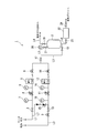
- the supply device 1 includes a base gas supply channel L1 for supplying a base gas, a source gas supply channel L2 for supplying a source gas, the base gas supply channel L1, and the source material.
- a bypass flow path L7 provided to communicate with the gas supply flow path L2, and a buffer tank (mixed gas storage tank) 2 for storing the hydrogen selenide mixed gas adjusted to a predetermined concentration. It is roughly structured.
- the base gas is not particularly limited as long as it is an inert gas for dilution use.
- the gas include nitrogen (N 2 ) gas, argon (Ar) gas, and the like.
- an opening / closing valve 3 In the base gas supply flow path L1, an opening / closing valve 3, a pressure regulator 4, a mass flow controller (MFC) 5, and an automatic valve 6 are sequentially provided from the upstream side to the downstream side.
- Pressure gauges 7 and 8 are provided on the upstream side and the downstream side of the pressure regulator 4, respectively, so that the pressure before and after the pressure regulator 4 can be visually recognized.
- the pressure regulator 4 is provided to reduce the pressure of the base gas supplied from the base gas supply source to a desired pressure.
- the supply apparatus 1 of the present embodiment only one pressure regulator 4 is shown in the base gas supply flow path L1, but the present invention is not limited to this, and two or more pressure regulators 4 are provided. May be.
- the pressure immediately before the mass flow controller 5 can be appropriately selected according to the supply pressure to the solar cell manufacturing apparatus.
- the pressure immediately before the mass flow controller 5 can be in the range of 0.6 to 0.7 MPa.
- the mass flow controller 5 is a flow control device that measures the flow rate of the base gas by measuring the mass flow rate of the base gas, and can perform highly accurate flow rate measurement and control.
- the mass flow sensor mounted on the mass flow controller 5 is not particularly limited, and a general one such as a thermal mass flow sensor or a differential pressure mass flow sensor can be used.
- the source gas supply channel L2 has one end connected to a source gas supply source (not shown) and the other end connected to a mixer (not shown).
- the source gas is hydrogen selenide (H 2 Se) gas having a concentration of 100%. In the present specification, it is simply referred to as 100% hydrogen selenide gas.
- an automatic valve (upstream flow path blocking means) 9 In the source gas supply flow path L2, from the upstream side toward the downstream side, an automatic valve (upstream flow path blocking means) 9, an open / close valve 10, a pressure regulator 11, a mass flow controller (flow rate control means) 12, automatic A valve (downstream channel blocking means) 14 is sequentially provided.
- Pressure gauges 15 and 16 are provided on the upstream side and the downstream side of the pressure regulator 11, respectively, so that the pressure before and after the pressure regulator 11 can be visually recognized.
- the pressure regulator 11 is provided to reduce the pressure of 100% hydrogen selenide gas supplied from the source gas supply source to a desired pressure.
- the supply apparatus 1 of the present embodiment only one pressure regulator 11 is shown in the raw material gas supply flow path L2, but this is not a limitation, and two or more pressure regulators 11 are provided. May be.
- the mass flow controller (MFC) 12 controls the flow rate of 100% hydrogen selenide gas in the raw material gas supply flow path L2, and the automatic valve 9 disposed on the upstream side in the raw material gas supply flow path L2 and the downstream side. It is provided between the arranged automatic valves 14.
- the mass flow controller 12 is a flow rate control device that controls the flow rate by measuring the mass flow rate of the raw material gas, and can perform highly accurate flow rate measurement and control.
- the mass flow sensor mounted on the mass flow controller 12 is not particularly limited, and a general one such as a thermal mass flow sensor or a differential pressure mass flow sensor can be used.
- the mixer (not shown) to which the base gas supply channel L1 and the source gas supply channel L2 are connected and the buffer tank 2 are connected by a channel L3.
- Open / close valves 17 and 18 are provided on the upstream side and the downstream side of the flow path L3, respectively.
- the buffer tank 2 is a storage tank for storing a hydrogen selenide mixed gas adjusted to a predetermined concentration by a mixer.
- the buffer tank 2 is provided on the downstream side of the base gas supply channel L1 and the source gas supply channel L2.
- capacitance of the buffer tank 2 is not specifically limited, According to the supply amount of the hydrogen selenide mixed gas to a solar cell manufacturing apparatus, it can select suitably.
- the buffer tank 2 is provided with a supply port (not shown). One end of the flow path L4 is connected to the supply port, and the other end of the flow path L4 is connected to the solar cell manufacturing apparatus. . Thereby, the hydrogen selenide mixed gas can be supplied from the buffer tank 2 to the solar cell manufacturing apparatus.
- An opening / closing valve 19 is provided on the supply port side of the flow path L4.
- one end of the flow path L5 is connected to the buffer tank 2, and the other end of the flow path L5 is connected to the pressure gauge 20. With the pressure gauge 20, the pressure in the buffer tank can be confirmed.
- An opening / closing valve 21 is provided in the flow path L5.
- the buffer tank 2 communicates with a flow path L6 branched from the flow path L3.
- the flow path L6 has one end connected to the flow path L3 and the other end connected to an exhaust duct (not shown).
- a gas concentration analyzer 22 is provided in the flow path L6. This gas concentration analyzer 22 can measure the hydrogen selenide concentration in the hydrogen selenide mixed gas stored in the buffer tank 2.
- open / close valves 23 and 24 are provided, respectively.
- the bypass flow path L7 is a flow path provided for supplying an inert gas from the base gas supply flow path L1 to the source gas supply flow path L2. As shown in FIG. 1, one end of the bypass flow path L7 is connected to the upstream side of the open / close valve 3 in the base gas supply flow path L1. Further, the other end of the bypass flow path L7 is between the upstream automatic valve 9 and the downstream automatic valve 14 of the source gas supply flow path L2, and the upstream automatic valve 9 side (specifically, In the supply apparatus 1 of this embodiment, it is connected between the on-off valve 10 and the pressure regulator 11).
- the base gas supply flow path L1 and the source gas supply flow path L2 are connected, and the inert gas can be supplied from the base gas supply flow path L1 to the source gas supply flow path L2.
- an automatic valve 25 is provided in the bypass flow path L7, and the flow path of the bypass flow path L7 can be freely opened and closed.
- the supply method of the present embodiment has a predetermined concentration by mixing the inert gas supplied from the base gas supply flow path L1 and the 100% hydrogen selenide gas supplied from the source gas supply flow path L2. It is the supply method of the hydrogen selenide mixed gas for solar cells which has the process of supplying the adjusted hydrogen selenide mixed gas. Then, after deriving a predetermined amount of 100% hydrogen selenide gas from the raw material gas supply flow path L2, an inert gas is derived from the raw material gas supply flow path L2 via the bypass flow path L7, and a predetermined concentration is obtained. The hydrogen selenide mixed gas is prepared, and the volume concentration of hydrogen selenide in the gas remaining in the raw material gas supply channel L2 is set to 10% or less.
- an upper limit value and a lower limit value are set for the filling pressure of the hydrogen selenide mixed gas having a predetermined concentration filled in the buffer tank 2, and the pressure in the buffer tank 2 is set.
- the badge system is used to start or stop the supply of the inert gas and 100% hydrogen selenide gas by the following first to third steps.
- (First step) In the first step, when the filling amount of the hydrogen selenide mixed gas in the mixed gas buffer tank 6 reaches the set lower limit value, a predetermined amount of inert gas is led out from the base gas supply flow path L1. By deriving a predetermined amount of 100% hydrogen selenide gas from the source gas supply flow path L2, a hydrogen selenide mixed gas having a predetermined concentration is supplied to the buffer tank 2.
- the automatic valve 6 provided in the base gas supply flow path L1 and the source gas supply flow path L2 A supply start signal is transmitted to the provided automatic valves 9, 14, and the automatic valves 6, 9, 14 are opened.
- an inert gas is supplied from a base gas supply source (not shown) to the base gas supply flow path L1, and 100% selenization is performed from a raw material gas supply source (not shown).
- Hydrogen gas is supplied to the source gas supply flow path L2.
- the inert gas controlled to a predetermined flow rate by the mass flow controller 5 is led out from the base gas supply flow path L1, and 100% hydrogen selenide gas controlled to the predetermined flow rate by the mass flow controller 12 is the source gas. It is led out from the supply flow path L2 and introduced into a mixer (not shown). An inert gas and a 100% hydrogen selenide gas introduced into the mixer at a predetermined flow rate ratio are mixed to obtain a hydrogen selenide mixed gas having a predetermined concentration, and then to the buffer tank 2 via the flow path L3. Supplied.
- the concentration of hydrogen selenide in the hydrogen selenide mixed gas is not particularly limited, and can be appropriately selected according to the requirements of the solar electric manufacturing apparatus. Specifically, for example, the concentration of hydrogen selenide in the hydrogen selenide mixed gas can be 5 to 20 vol%.
- the hydrogen selenide concentration in the hydrogen selenide mixed gas stored in the buffer tank 2 can be measured by the gas concentration analyzer 22.
- a supply stop signal is transmitted to 9, 14 and these automatic valves 6, 9, 14 are closed.
- these automatic valves 6, 9, and 14 are closed, the supply of the inert gas from the base gas supply source (not shown) to the base gas supply flow path L1 is stopped and the source gas is supplied from the source gas supply source (not shown).
- the supply of 100% hydrogen selenide gas to the supply flow path L2 is stopped. Thereby, the derivation of the inert gas from the base gas supply channel L1 and the derivation of the predetermined amount of 100% hydrogen selenide gas from the source gas supply channel L2 are completed.
- a supply signal is transmitted to the automatic valves 9 and 14 provided in the source gas supply flow path L2, and the automatic valves 9 and 14 are opened for a predetermined time. During this time, a predetermined amount of 100% hydrogen selenide gas is further led out from the source gas supply flow path L2. The derived 100% hydrogen selenide gas is supplied to the buffer tank 2 through the flow path 3. Then, after a predetermined time has elapsed, the automatic valves 9 and 14 are closed. This completes the derivation of the predetermined additional amount of 100% hydrogen selenide gas from the source gas supply flow path L2.
- the hydrogen selenide concentration in the hydrogen selenide mixed gas stored in the buffer tank 2 in the first step is slightly To increase. Therefore, it is preferable to reduce the supply amount of 100% hydrogen selenide gas added in the second step as much as possible.
- the additional amount of 100% hydrogen selenide gas can be determined by appropriately adjusting the flow rate set by the mass flow controller 12 and the opening times of the automatic valves 9 and 14.
- a predetermined additional amount corresponding to the predetermined additional amount of the 100% hydrogen selenide gas after the derivation of the predetermined additional amount of 100% hydrogen selenide gas from the source gas supply flow path L2 is completed.
- the base gas is led out from the source gas supply flow path L2 via the bypass path L7.
- a supply signal is transmitted to the automatic valve 25 provided in the bypass flow path L7 and the automatic valve 14 provided in the source gas supply flow path L2.
- the automatic valves 14 and 25 are opened for a predetermined time. During this time, a predetermined additional amount of inert gas is introduced from the base gas supply channel L1 to the source gas supply channel L2 via the bypass channel L2. Then, the inert gas derived from the source gas supply flow path L2 is supplied to the buffer tank 2 through the flow path 3. Next, after a predetermined time has elapsed, the automatic valves 14 and 25 are closed. Thereby, the derivation of the predetermined additional amount of the inert gas from the source gas supply flow path L2 is completed.
- the hydrogen selenide concentration in the hydrogen selenide mixed gas stored in the buffer tank 2 is the first step.
- the supply amount of the inert gas added in the third step is 100 so that the concentration of hydrogen selenide in the hydrogen selenide mixed gas becomes the target concentration (that is, the concentration adjusted in the first step). It is preferable to adjust the supply amount according to the additional amount of% hydrogen selenide gas.
- the supply amount of the inert gas can be adjusted by appropriately changing the opening time of the automatic valve 14.
- the inside of the raw material gas supply flow path L2 is completed when the third step is completed. That is, the inside of the flow path on the downstream side from the automatic valve 9 provided on the upstream side is replaced with the inert gas.
- the above mixed gas mainly composed of an inert gas contains a slight amount of hydrogen selenide.
- the concentration of hydrogen selenide contained in this mixed gas is preferably 10% or less. If the concentration exceeds 10%, hydrogen selenide tends to self-decompose into hydrogen and selenium, and selenium crystals tend to precipitate in the source gas supply flow path L2, which is not preferable. On the other hand, since the self-decomposition of hydrogen selenide can be suppressed if the concentration is 10% or less, precipitation of selenium crystals into the source gas supply channel L2 can be effectively reduced. .
- the pressure adjustment provided in the flow path sealed by the source gas supply flow path L2 (that is, the section between the automatic valve 9 provided on the upstream side and the automatic valve 14 provided on the downstream side). Precipitation of selenium crystals in the vessel 11 and the mass flow controller 12 can also be reduced. As a result, when a predetermined flow rate of inert gas and 100% hydrogen selenide gas are mixed and the hydrogen selenide mixed gas is adjusted to a predetermined concentration, 100% hydrogen selenide gas is supplied at a stable flow rate. be able to.
- the base gas And all can be made into product gas (hydrogen selenide mixed gas), without discarding raw material gas.
- the selenization stored in the buffer tank 2 by adjusting the quantity ratio of the additional inert gas and 100% hydrogen selenide gas derived from the source gas supply path L2 in the second step and the third step.
- the concentration of hydrogen selenide in the hydrogen mixed gas can be adjusted to a predetermined concentration.
- the supply method of this embodiment is characterized by repeating the first step to the third step.
- a hydrogen selenide mixed gas having a predetermined concentration can be prepared while the mixing ratio of the inert gas and the 100% hydrogen selenide gas is always kept constant. .
- the error between the set value of the hydrogen selenide concentration in the hydrogen selenide mixed gas and the measured value can always be kept small, the drift phenomenon of the hydrogen selenide concentration can be suppressed.
- a hydrogen selenide mixed gas having a stable hydrogen selenide concentration is continuously supplied to the solar cell manufacturing apparatus.
- the cycle from the first step to the third step is referred to as one badge.
- the hydrogen selenide mixed gas supply device 1 for the solar cell includes the base gas supply channel L1, the source gas supply channel L2, the base gas supply channel L1, and the source gas supply. Since the bypass flow path L7 is provided so as to communicate with the flow path L2, the inert gas is supplied from the base gas supply flow path L1 to the source gas supply flow path L2 via the bypass flow path L7. Can be derived. Thereby, the inside of the source gas supply flow path L2 can be replaced with the inert gas, and the hydrogen selenide concentration can be reduced.
- automatic valves (flow path blocking means) 9 and 14 are provided on the upstream side and the downstream side of the source gas supply flow path L2, respectively, and the bypass flow path L7 is automatically connected to the upstream side of the source gas supply flow path L2. Since it is connected between the valve 9 and the downstream automatic valve 14 and is connected to the upstream automatic valve 14 side, the inside of the source gas supply flow path L2 can be sealed. As a result, a gas mainly composed of an inert gas can be sealed in the sealed flow path of the source gas supply flow path L2.
- the supply device 1 of the present embodiment includes the buffer tank 2, the hydrogen selenide mixed gas adjusted to a predetermined concentration can be stored. Thereby, hydrogen selenide mixed gas can be suitably supplied to a solar cell manufacturing apparatus according to the situation of production.
- the method for supplying the hydrogen selenide mixed gas for solar cell of the present embodiment is as follows. After the 100% hydrogen selenide gas is derived from the source gas supply channel L2, it is not supplied from the source gas supply channel L2 via the bypass channel L7. By deriving the active gas, a hydrogen selenide mixed gas having a predetermined concentration is prepared, and the volume concentration of hydrogen selenide remaining in the raw material gas supply channel is set to 10% or less. Thereby, the self-decomposition of hydrogen selenide is suppressed, and precipitation of selenium crystals into the raw material gas supply flow path is reduced, so that 100% hydrogen selenide gas can be stably supplied. Therefore, a hydrogen selenide mixed gas having a stable hydrogen selenide concentration can be continuously supplied to the solar cell manufacturing apparatus.
- a first step for deriving a predetermined amount of inert gas and 100% hydrogen selenide gas from the respective supply flow paths L1, L2, and a source gas supply flow path for a predetermined additional amount of 100% hydrogen selenide gas A second step of deriving from L2, and a third step of deriving an amount of inert gas corresponding to the additional amount of 100% hydrogen selenide gas from the source gas supply flow path L2 via the bypass path L7. Therefore, it is possible to easily adjust the amount ratio of the additional inert gas and 100% hydrogen selenide gas derived from the source gas supply path L2 in the second step and the third step to a predetermined value.
- the hydrogen selenide mixed gas in which the mixing ratio of the inert gas and the 100% hydrogen selenide gas is always kept constant that is, the hydrogen selenide concentration is stabilized
- the buffer tank 2 is provided on the downstream side of the base gas supply channel L1 and the raw material gas supply channel L2, the inert gas and 100% hydrogen selenide gas derived from the supply channels L1 and L2 are provided. All of the above can be supplied to the buffer tank 2. Thereby, it can be set as all product gas (hydrogen selenide mixed gas), without discarding base gas and source gas.
- the flow rate of 100% hydrogen selenide gas is controlled using the mass flow controller 12 in the source gas supply flow path L2, but the flow rate of the 100% hydrogen selenide gas is changed.
- the structure is not particularly limited as long as it can be controlled.
- the flow rate may be controlled using flow control means such as an orifice or a needle valve that simply restricts the flow rate and pressure control means such as an automatic pressure control device (APR).
- APR automatic pressure control device
- the automatic valves 6, 9, and 14 are opened, and nitrogen (N 2 ) gas as an inert gas is supplied from the base gas supply flow path L1, and 100% hydrogen selenide gas is supplied from the source gas supply flow path L2 to the buffer tank 2 respectively. Supplied. When the pressure in the buffer tank 2 reached the upper limit of 0.4 MPa, the automatic valves 6, 9, and 14 were closed (first step).
- the automatic valves 14 and 25 were opened for 25.6 seconds and then closed (third step).
- the volume concentration of hydrogen selenide in the hydrogen selenide mixed gas in the buffer tank 2 was measured by the densitometer 22 and confirmed to be 20%.
- the hydrogen selenide mixed gas of hydrogen selenide 0.67 (L), nitrogen 2.68 (L), and total 3.35 (L) is additionally introduced by the second and third steps, the supply is completed.
- Example 1 The hydrogen selenide mixed gas was continuously supplied to the solar cell manufacturing apparatus using the supply apparatus 1 shown in FIG.
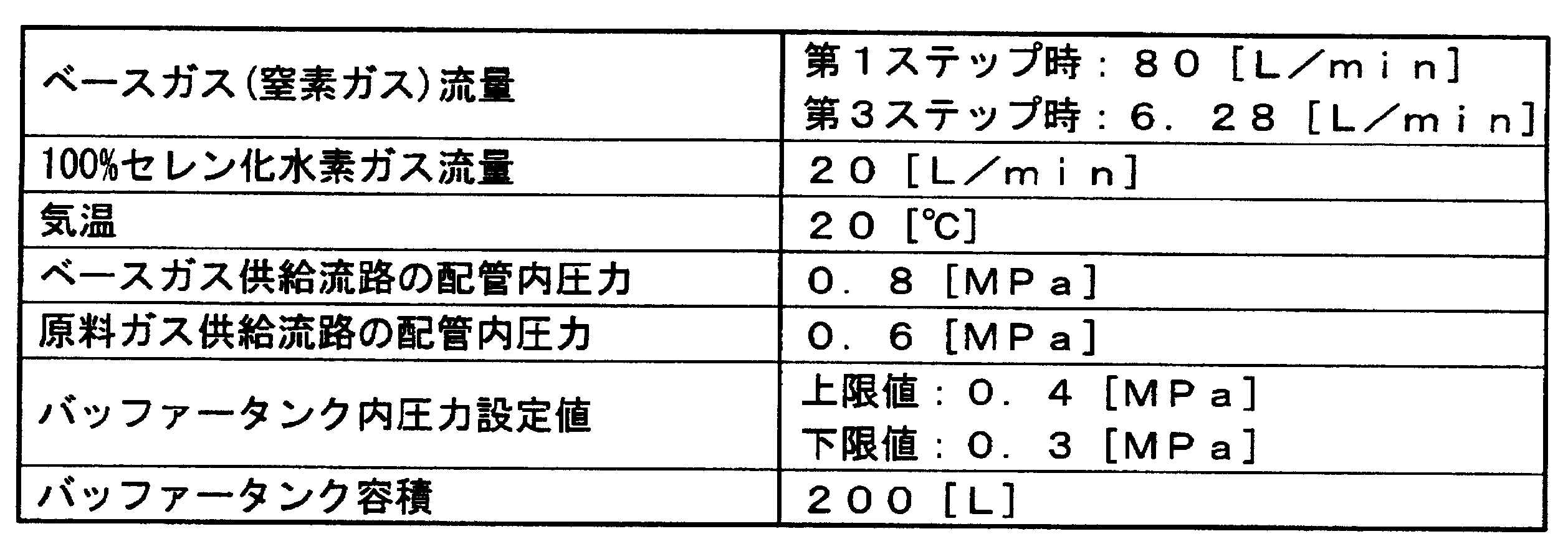
- the conditions of the supply device 1 when supplying the hydrogen selenide mixed gas the conditions shown in Table 1 and the verification results of the test 1 were used.
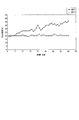
- the concentration change of the mixed gas was recorded using the gas concentration analyzer 22 connected to the buffer tank 2. The results are shown in FIG.
- Example 2 The hydrogen selenide mixed gas was continuously supplied to the solar cell manufacturing apparatus using the supply apparatus 101 shown in FIG.
- the batch method using the buffer tank 102 was used for continuous supply of the hydrogen selenide mixed gas to the solar cell manufacturing apparatus, and the conditions shown in Table 1 were used as supply conditions for the hydrogen selenide mixed gas of the supply apparatus 101. .
- the concentration change of the mixed gas was recorded using the gas concentration analyzer 122 connected to the buffer tank 102. The results are shown in FIG.
- the measured concentration of the hydrogen selenide mixed gas in the buffer tank 102 in Example 2 which is the prior art fluctuated between 19 and 41% with respect to the set concentration of 20%.
- the actual concentration of the hydrogen selenide mixed gas in the buffer tank 2 in Example 1 to which the present invention is applied is suppressed to 19 to 21% with respect to the set concentration of 20%, and the fluctuation range of the concentration Was confirmed to be shrinking.
- Example 2 which is a conventional technique, it was confirmed that about 100 mg of selenium (Se) crystals were deposited on the piping which is the raw material gas supply flow path L102 and the sensor portion of the mass flow controller (MFC) 112. On the other hand, in Example 1 to which the present invention was applied, precipitation of selenium crystals could not be visually confirmed in the source gas supply flow path L2 and the mass flow controller 12.
Landscapes
- Chemical & Material Sciences (AREA)
- Organic Chemistry (AREA)
- Inorganic Chemistry (AREA)
- Photovoltaic Devices (AREA)
- Fuel Cell (AREA)
Abstract
Description
本願は、2009年10月14日に、日本に出願された特願2009-237154号に基づき優先権を主張し、その内容をここに援用する。
本発明の第1の態様は、ベースガス供給流路から供給される不活性ガスと、原料ガス供給流路から供給される100%セレン化水素ガスと、を混合することにより所定の濃度に調整したセレン化水素混合ガスを供給する工程を有する太陽電池用セレン化水素混合ガスの供給方法であって、
前記ベースガス供給流路と前記原料ガス供給流路とには、互いに連通するバイパス流路が設けられており、
所定の量の前記100%セレン化水素ガスを前記原料ガス供給流路から導出した後に、前記バイパス流路を介して前記原料ガス供給流路から前記不活性ガスを導出して所定の濃度のセレン化水素混合ガスを調製し、且つ前記原料ガス供給流路に残存するセレン化水素の体積濃度を10%以下とする(dilute)太陽電池用セレン化水素混合ガスの供給方法である。
上流側及び下流側の前記流路遮断手段によって封止された前記原料ガス供給流路内のセレン化水素の体積濃度を10%以下とすることが好ましい。
所定の追加分量の前記100%セレン化水素ガスを前記原料ガス供給流路から導出する第2ステップと、
前記100%セレン化水素ガスの前記所定の追加分量に応じて、所定の追加分量の前記不活性ガスを、前記バイパス経路を介して前記原料ガス供給流路から導出する第3ステップと、を備えることが好ましい。
前記第1乃至第3ステップで導出された不活性ガス及び100%セレン化水素ガスの全てを前記混合ガス貯留槽に供給して当該混合ガス貯留槽内における前記セレン化水素混合ガス中のセレン化水素の体積濃度を所定の濃度に調整することが好ましい。
原料ガス供給流路と、
前記ベースガス供給流路と前記原料ガス供給流路とを連通するように設けられたバイパス流路と、
前記原料ガス供給流路の上流側及び下流側にそれぞれ設けられた流路遮断手段と、を備え、
前記バイパス流路が前記原料ガス供給流路の上流側の流路遮断手段と下流側の流路遮断手段との間であって前記上流側の流路遮断手段側に接続されており、
ベースガス供給流路から供給される不活性ガスと、原料ガス供給流路から供給される100%セレン化水素ガスと、を混合することにより所定の濃度に調整したセレン化水素混合ガスを供給する太陽電池用セレン化水素混合ガスの供給装置である。
前記流量制御手段が、前記上流側の流路遮断手段と前記下流側の流路遮断手段との間に配置されていることが好ましい。
なお、以下の説明で用いる図面は、特徴をわかりやすくするために、便宜上特徴となる部分を拡大して示している場合があり、各構成要素の寸法比率などが実際と同じであるとは限らない。
また、本明細書中で用いる単位については、濃度は体積濃度、圧力はゲージ圧力、流量は体積流量を表している。さらに、本明細書中に示す体積は、基準状態(0℃、1atm(大気圧))での体積である。
図1に示すように、本実施形態の供給装置1は、太陽電池の製造装置における生産状況に応じて、所定の濃度に調整したセレン化水素混合ガスを供給する装置である。具体的には、供給装置1は、ベースガスを供給するためのベースガス供給流路L1と、原料ガスを供給するための原料ガス供給流路L2と、上記ベースガス供給流路L1と上記原料ガス供給流路L2とを連通するように設けられたバイパス流路L7と、所定の濃度に調整されたセレン化水素混合ガスを貯留するためのバッファータンク(混合ガス貯留槽)2と、を備えて概略構成されている。
ベースガスは、希釈用途の不活性ガスであれば特に限定されるものではない。上記ガスとしては、例えば、窒素(N2)ガス、アルゴン(Ar)ガス等が挙げられる。
なお、マスフローコントローラ5の直前の圧力は、太陽電池製造装置への供給圧力に応じて適宜選択することができる。例えば、マスフローコントローラ5の直前の圧力としては、0.6~0.7MPaの範囲とすることができる。
原料ガスは、濃度100%のセレン化水素(H2Se)ガスである。なお、本明細書中では、単に100%セレン化水素ガスと記載する。
本実施形態の供給方法は、ベースガス供給流路L1から供給される不活性ガスと、原料ガス供給流路L2から供給される100%セレン化水素ガスと、を混合することにより所定の濃度に調整したセレン化水素混合ガスを供給する工程を有する太陽電池用セレン化水素混合ガスの供給方法である。そして、所定の量の100%セレン化水素ガスを原料ガス供給流路L2から導出した後に、バイパス流路L7を介して上記原料ガス供給流路L2から不活性ガスを導出し、所定の濃度のセレン化水素混合ガスを調製すると共に上記原料ガス供給流路L2に残存する気体中におけるセレン化水素の体積濃度を10%以下とすることを特徴とするものである。
第1ステップでは、混合ガス用バッファータンク6中のセレン化水素混合ガスの充填量が設定した下限値となったときに、所定の量の不活性ガスをベースガス供給流路L1から導出するとともに所定の量の100%セレン化水素ガスを原料ガス供給流路L2から導出することにより、バッファータンク2へ所定の濃度のセレン化水素混合ガスを供給する。
なお、バッファータンク2に貯留されるセレン化水素混合ガス中のセレン化水素濃度は、ガス濃度分析計22によって測定することができる。
第2ステップでは、所定の量の不活性ガスのベースガス供給流路L1からの導出及び所定の量の100%セレン化水素ガスの原料ガス供給流路L2からの導出が完了した後に、所定の追加分量の100%セレン化水素ガスを原料ガス供給流路L2からさらに導出する。
第3ステップでは、所定の追加分量の100%セレン化水素ガスの原料ガス供給流路L2からの導出が完了した後に、上記100%セレン化水素ガスの所定の追加分量に応じた所定の追加分量のベースガスを、バイパス経路L7を経て原料ガス供給流路L2から導出する。
なお、本実施形態の供給方法において、上記第1ステップから第3ステップのサイクルを1バッジと称する。
(試験1)
図1に示す供給装置1を用いて太陽電池製造装置にセレン化水素混合ガスを供給する際に、バッファータンク2内のセレン化水素混合ガス中のセレン化水素の体積濃度を20%に保つことが可能な、100%セレン化水素ガスの追加分量と、それに応じた不活性ガスの追加分量とを検証した。
また、供給装置1の条件としては、表1の条件を用いた。なお、図1に示す供給装置1において、自動弁9及び自動弁25の入口には、直径0.5mmのオリフィスが設置されており、バイパス経路7を経由する際のベースガス流量は6.28L/minに制限されていた。
試験1においては、特に記載がない限り、圧力はゲージ圧力、流量は体積流量、体積は基準状態(0℃、大気圧(1atm=101.3kPa))での体積を表している。
2(s)×20(L/min)×1(min)/60(s)=0.67(L)・・・(1)
ここで、0.67Lのセレン化水素(H2Se)を20%に希釈するために必要な窒素ガスの量Xは、下式(2)及び(3)に示すように2.68Lであった。
0.67/(0.67+X)=0.2・・・(2)
X=(0.67-(0.2×0.67))/0.2=2.68(L)・・・(3)
また、窒素ガスを2.68L供給するために自動弁25を開放する時間は、下式(4)に示すように25.6秒であった。
2.68(L)/((6.28(L/min)×1(min)/60(s))=25.6(s)・・・(4)
また、バッファータンク2の容積は200Lであり、上記第1ステップの完了後のバッファータンク2の圧力が0.4MPaであるため、第1ステップの完了後のバッファータンク内のガス(セレン化水素+窒素)の体積は、基準状態での体積に換算すると、下式(5)に示すように989.73(L)であった。
200×(0.1013+0.4)/0.1013=989.73(L)・・・(5)
さらに、上記第2及び第3ステップによりセレン化水素0.67(L)、窒素2.68(L)、合計3.35(L)のセレン化水素混合ガスが追加流入するため、供給完了後(第3ステップ完了後)のバッファータンク2内の圧力は、下式(6)に示すように0.402MPaとなった。
(0.1013×(989.73+3.35)/200)-0.1013=0.402・・・(6)
更にまた、供給完了後(第3ステップ完了後)の原料ガス供給流路L2内の希釈率は99%以上であり、セレン化水素濃度が十分に低減されていることを確認した。
図1に示す供給装置1を用いて、太陽電池製造装置にセレン化水素混合ガスを連続して供給した。
また、セレン化水素混合ガスの供給時の、供給装置1の条件としては、表1の条件及び上記試験1の検証結果を用いた。
上記実施条件において、太陽電池製造装置にセレン化水素混合ガスを連続して供給する際、バッファータンク2に接続されたガス濃度分析計22を用いて混合ガスの濃度変化を記録した。結果を図2に示す。
図3に示す供給装置101を用いて、太陽電池製造装置にセレン化水素混合ガスを連続して供給した。太陽電池製造装置へのセレン化水素混合ガスの連続供給には、バッファータンク102を用いたバッチ方式を用い、供給装置101のセレン化水素混合ガスの供給条件としては、表1の条件を用いた。
上記実施条件において、太陽電池製造装置にセレン化水素混合ガスを連続して供給する際、バッファータンク102に接続されたガス濃度分析計122を用いて混合ガスの濃度変化を記録した。結果を図2に示す。
2…バッファータンク(混合ガス貯留槽)
3,10,14,17,18,19,21,23,24…開閉バルブ
4,11…圧力調整器
5,12…マスフローコントローラ(流量制御手段)
6,9,14,25…自動弁(流路遮断手段)
7,8,15,16,20…圧力計
22…ガス濃度分析計
L1…ベースガス供給流路
L2…原料ガス供給流路
L3~L6…流路
L7…バイパス流路
Claims (7)
- ベースガス供給流路から供給される不活性ガスと、原料ガス供給流路から供給される100%セレン化水素ガスと、を混合することにより所定の濃度に調整したセレン化水素混合ガスを供給する工程を有する太陽電池用セレン化水素混合ガスの供給方法であって、
前記ベースガス供給流路と前記原料ガス供給流路とには、互いに連通するバイパス流路が設けられており、
所定の量の前記100%セレン化水素ガスを前記原料ガス供給流路から導出した後に、前記バイパス流路を介して前記原料ガス供給流路から前記不活性ガスを導出して、所定の濃度のセレン化水素混合ガスを調製し、且つ前記原料ガス供給流路に残存するセレン化水素の体積濃度を10%以下とする太陽電池用セレン化水素混合ガスの供給方法。 - 前記原料ガス供給流路の上流側及び下流側にはそれぞれ流路遮断手段が設けられ、
上流側及び下流側の前記流路遮断手段によって封止された前記原料ガス供給流路内のセレン化水素の体積濃度を10%以下とする請求項1に記載の太陽電池用セレン化水素混合ガスの供給方法。 - 前記供給工程が、所定の量の前記不活性ガスを前記ベースガス供給流路から導出するとともに所定の量の前記100%セレン化水素ガスを前記原料ガス供給流路から導出する第1ステップと、
所定の追加分量の前記100%セレン化水素ガスを前記原料ガス供給流路から導出する第2ステップと、
前記100%セレン化水素ガスの前記所定の追加分量に応じて、所定の追加分量の前記不活性ガスを、前記バイパス経路を介して前記原料ガス供給流路から導出する第3ステップと、を備える請求項1に記載の太陽電池用セレン化水素混合ガスの供給方法。 - 前記ベースガス供給流路及び前記原料ガス供給流路の下流側には、混合ガス貯留槽が設けられており、
前記第1乃至第3ステップで導出された不活性ガス及び100%セレン化水素ガスの全てを前記混合ガス貯留槽に供給して当該混合ガス貯留槽内における前記セレン化水素混合ガス中のセレン化水素の体積濃度を所定の濃度に調整する請求項1に記載の太陽電池用セレン化水素混合ガスの供給方法。 - ベースガス供給流路と、
原料ガス供給流路と、
前記ベースガス供給流路と前記原料ガス供給流路とを連通するように設けられたバイパス流路と、
前記原料ガス供給流路の上流側及び下流側にそれぞれ設けられた流路遮断手段と、を備え、
前記バイパス流路が前記原料ガス供給流路の上流側の流路遮断手段と下流側の流路遮断手段との間であって前記上流側の流路遮断手段側に接続されており、
ベースガス供給流路から供給される不活性ガスと、原料ガス供給流路から供給される100%セレン化水素ガスと、を混合することにより所定の濃度に調整したセレン化水素混合ガスを供給する太陽電池用セレン化水素混合ガスの供給装置。 - 前記原料ガス供給流路には、前記100%セレン化水素ガスの流量を制御するための流量制御手段が設けられており、
前記流量制御手段が、前記上流側の流路遮断手段と前記下流側の流路遮断手段との間に配置されている請求項5に記載の太陽電池用セレン化水素混合ガスの供給装置。 - 前記ベースガス供給流路及び前記原料ガス供給流路の下流側に設けられた混合ガス貯留槽と、
前記混合ガス貯留槽に貯留されるセレン化水素混合ガス中のセレン化水素濃度を測定するガス濃度分析計と、をさらに備える請求項5に記載の太陽電池用セレン化水素混合ガスの供給装置。
Priority Applications (3)
| Application Number | Priority Date | Filing Date | Title |
|---|---|---|---|
| JP2011536076A JP5663488B2 (ja) | 2009-10-14 | 2010-08-27 | 太陽電池用セレン化水素混合ガスの供給方法及び供給装置 |
| CN201080035130.9A CN102471062B (zh) | 2009-10-14 | 2010-08-27 | 太阳能电池用硒化氢混合气体的供给方法以及供给装置 |
| KR1020127003216A KR101641194B1 (ko) | 2009-10-14 | 2010-08-27 | 태양 전지용 셀렌화 수소 혼합가스의 공급방법 및 공급장치 |
Applications Claiming Priority (2)
| Application Number | Priority Date | Filing Date | Title |
|---|---|---|---|
| JP2009-237154 | 2009-10-14 | ||
| JP2009237154 | 2009-10-14 |
Publications (1)
| Publication Number | Publication Date |
|---|---|
| WO2011045983A1 true WO2011045983A1 (ja) | 2011-04-21 |
Family
ID=43876038
Family Applications (1)
| Application Number | Title | Priority Date | Filing Date |
|---|---|---|---|
| PCT/JP2010/064598 Ceased WO2011045983A1 (ja) | 2009-10-14 | 2010-08-27 | 太陽電池用セレン化水素混合ガスの供給方法及び供給装置 |
Country Status (5)
| Country | Link |
|---|---|
| JP (1) | JP5663488B2 (ja) |
| KR (1) | KR101641194B1 (ja) |
| CN (1) | CN102471062B (ja) |
| TW (1) | TWI504432B (ja) |
| WO (1) | WO2011045983A1 (ja) |
Cited By (4)
| Publication number | Priority date | Publication date | Assignee | Title |
|---|---|---|---|---|
| JP2013135133A (ja) * | 2011-12-27 | 2013-07-08 | Honda Motor Co Ltd | 太陽電池用成膜装置及び太陽電池用成膜方法 |
| JP2014084241A (ja) * | 2012-10-22 | 2014-05-12 | Taiyo Nippon Sanso Corp | 太陽電池用セレン化水素混合ガスの供給方法 |
| JP2015013784A (ja) * | 2013-07-08 | 2015-01-22 | 大陽日酸株式会社 | セレン化水素混合ガス供給装置 |
| KR20150044437A (ko) | 2012-10-22 | 2015-04-24 | 다이요 닛산 가부시키가이샤 | 셀렌화수소 혼합 가스의 공급 방법 및 공급 장치 |
Families Citing this family (2)
| Publication number | Priority date | Publication date | Assignee | Title |
|---|---|---|---|---|
| AT523678B1 (de) * | 2020-03-27 | 2021-12-15 | Avl List Gmbh | Dosiereinheit zur Erzeugung eines Mischgases |
| KR102206711B1 (ko) * | 2020-11-05 | 2021-01-25 | 김흥구 | 도펀트 가스 혼합 시스템 |
Citations (2)
| Publication number | Priority date | Publication date | Assignee | Title |
|---|---|---|---|---|
| JP2008013414A (ja) * | 2006-07-07 | 2008-01-24 | Sumitomo Electric Ind Ltd | セレン化亜鉛多結晶およびその製造方法 |
| JP2008543563A (ja) * | 2005-06-22 | 2008-12-04 | アドバンスド テクノロジー マテリアルズ,インコーポレイテッド | 一体型のガス混合装置およびプロセス |
Family Cites Families (10)
| Publication number | Priority date | Publication date | Assignee | Title |
|---|---|---|---|---|
| JPH0647734B2 (ja) * | 1986-02-27 | 1994-06-22 | キヤノン株式会社 | 堆積膜形成法 |
| JPH11265218A (ja) * | 1998-03-18 | 1999-09-28 | Kokusai Electric Co Ltd | 自動流量/流量比変換データ校正装置及びガス供給装置 |
| JP2000150542A (ja) * | 1998-11-06 | 2000-05-30 | Asahi Chem Ind Co Ltd | Ib−IIIb−VIb2族化合物半導体薄膜の形成方法およびこの方法で使用される成膜装置 |
| EP1556902A4 (en) * | 2002-09-30 | 2009-07-29 | Miasole | MANUFACTURING DEVICE AND METHOD FOR PRODUCING THIN FILM SOLAR CELLS IN A LARGE SCALE |
| JP4925724B2 (ja) * | 2006-05-25 | 2012-05-09 | 本田技研工業株式会社 | 太陽電池およびその製造方法 |
| WO2008057119A1 (en) * | 2006-11-09 | 2008-05-15 | Midwest Research Institue | Formation of copper-indium-selenide and/or copper-indium-gallium-selenide films from indium selenide and copper selenide precursors |
| CN100567140C (zh) * | 2007-04-26 | 2009-12-09 | 大连立方化学技术有限公司 | 硒化氢的制备纯化方法 |
| CN100581995C (zh) * | 2008-05-09 | 2010-01-20 | 南开大学 | 一种用于硒化处理的高活性硒源的产生方法及装置和应用 |
| JP5518404B2 (ja) * | 2009-09-04 | 2014-06-11 | 大陽日酸株式会社 | 太陽電池用セレン化水素混合ガスの供給方法及び供給装置 |
| CN102471061B (zh) * | 2009-09-04 | 2014-09-24 | 大阳日酸株式会社 | 太阳能电池用硒化氢混合气体的供给方法以及供给装置 |
-
2010
- 2010-08-27 CN CN201080035130.9A patent/CN102471062B/zh not_active Expired - Fee Related
- 2010-08-27 KR KR1020127003216A patent/KR101641194B1/ko not_active Expired - Fee Related
- 2010-08-27 WO PCT/JP2010/064598 patent/WO2011045983A1/ja not_active Ceased
- 2010-08-27 JP JP2011536076A patent/JP5663488B2/ja not_active Expired - Fee Related
- 2010-08-30 TW TW099129049A patent/TWI504432B/zh not_active IP Right Cessation
Patent Citations (2)
| Publication number | Priority date | Publication date | Assignee | Title |
|---|---|---|---|---|
| JP2008543563A (ja) * | 2005-06-22 | 2008-12-04 | アドバンスド テクノロジー マテリアルズ,インコーポレイテッド | 一体型のガス混合装置およびプロセス |
| JP2008013414A (ja) * | 2006-07-07 | 2008-01-24 | Sumitomo Electric Ind Ltd | セレン化亜鉛多結晶およびその製造方法 |
Cited By (4)
| Publication number | Priority date | Publication date | Assignee | Title |
|---|---|---|---|---|
| JP2013135133A (ja) * | 2011-12-27 | 2013-07-08 | Honda Motor Co Ltd | 太陽電池用成膜装置及び太陽電池用成膜方法 |
| JP2014084241A (ja) * | 2012-10-22 | 2014-05-12 | Taiyo Nippon Sanso Corp | 太陽電池用セレン化水素混合ガスの供給方法 |
| KR20150044437A (ko) | 2012-10-22 | 2015-04-24 | 다이요 닛산 가부시키가이샤 | 셀렌화수소 혼합 가스의 공급 방법 및 공급 장치 |
| JP2015013784A (ja) * | 2013-07-08 | 2015-01-22 | 大陽日酸株式会社 | セレン化水素混合ガス供給装置 |
Also Published As
| Publication number | Publication date |
|---|---|
| KR101641194B1 (ko) | 2016-07-20 |
| JPWO2011045983A1 (ja) | 2013-03-04 |
| CN102471062A (zh) | 2012-05-23 |
| KR20120087884A (ko) | 2012-08-07 |
| CN102471062B (zh) | 2014-04-16 |
| TW201136658A (en) | 2011-11-01 |
| JP5663488B2 (ja) | 2015-02-04 |
| TWI504432B (zh) | 2015-10-21 |
Similar Documents
| Publication | Publication Date | Title |
|---|---|---|
| JP6065329B2 (ja) | セレン化水素混合ガスの供給方法及び供給装置 | |
| JP5548208B2 (ja) | 太陽電池用セレン化水素混合ガスの供給方法及び供給装置 | |
| JP5663488B2 (ja) | 太陽電池用セレン化水素混合ガスの供給方法及び供給装置 | |
| JP5518404B2 (ja) | 太陽電池用セレン化水素混合ガスの供給方法及び供給装置 | |
| US9556518B2 (en) | Raw material gas supply apparatus for semiconductor manufacturing equipment | |
| GB2273391A (en) | Apparatus for growing compound semiconductor layers | |
| CN102732956A (zh) | 一种用于MOCVD设备GaN外延MO源供给系统 | |
| TWM462748U (zh) | 混生氣體生成設備 | |
| JP5873231B2 (ja) | 太陽電池用セレン化水素混合ガスの供給装置及び供給方法 | |
| JP5378122B2 (ja) | 太陽電池用セレン化水素混合ガスの供給方法及び供給装置 | |
| CN209227101U (zh) | 双层外延片的制造设备 | |
| CN121204815A (zh) | 一种双前驱体雾化系统及制备镓铟氧化物薄膜的方法 | |
| KR20090118428A (ko) | 반도체 제조 공정용 희석가스 공급장치 및 그 방법 | |
| JP6008688B2 (ja) | 太陽電池用セレン化水素混合ガスの供給方法 | |
| KR20120091564A (ko) | 가스공급장치 및 이를 제어하는 방법 | |
| EP4361323A1 (en) | Dilution device for epitaxial doping gas | |
| CN101290877A (zh) | 多晶硅薄膜的制备方法 | |
| JPH076964A (ja) | 半導体の製造方法 | |
| JPS6390121A (ja) | 気相結晶成長装置 | |
| JP2013135133A (ja) | 太陽電池用成膜装置及び太陽電池用成膜方法 |
Legal Events
| Date | Code | Title | Description |
|---|---|---|---|
| WWE | Wipo information: entry into national phase |
Ref document number: 201080035130.9 Country of ref document: CN |
|
| 121 | Ep: the epo has been informed by wipo that ep was designated in this application |
Ref document number: 10823251 Country of ref document: EP Kind code of ref document: A1 |
|
| WWE | Wipo information: entry into national phase |
Ref document number: 2011536076 Country of ref document: JP |
|
| ENP | Entry into the national phase |
Ref document number: 20127003216 Country of ref document: KR Kind code of ref document: A |
|
| NENP | Non-entry into the national phase |
Ref country code: DE |
|
| 122 | Ep: pct application non-entry in european phase |
Ref document number: 10823251 Country of ref document: EP Kind code of ref document: A1 |