WO2011043317A1 - 省電力化システム、及び省電力化方法 - Google Patents
省電力化システム、及び省電力化方法 Download PDFInfo
- Publication number
- WO2011043317A1 WO2011043317A1 PCT/JP2010/067414 JP2010067414W WO2011043317A1 WO 2011043317 A1 WO2011043317 A1 WO 2011043317A1 JP 2010067414 W JP2010067414 W JP 2010067414W WO 2011043317 A1 WO2011043317 A1 WO 2011043317A1
- Authority
- WO
- WIPO (PCT)
- Prior art keywords
- server
- rack
- power saving
- management unit
- switch
- Prior art date
Links
Images


Classifications
-
- H—ELECTRICITY
- H04—ELECTRIC COMMUNICATION TECHNIQUE
- H04L—TRANSMISSION OF DIGITAL INFORMATION, e.g. TELEGRAPHIC COMMUNICATION
- H04L12/00—Data switching networks
- H04L12/02—Details
- H04L12/10—Current supply arrangements
-
- G—PHYSICS
- G06—COMPUTING; CALCULATING OR COUNTING
- G06F—ELECTRIC DIGITAL DATA PROCESSING
- G06F1/00—Details not covered by groups G06F3/00 - G06F13/00 and G06F21/00
- G06F1/26—Power supply means, e.g. regulation thereof
- G06F1/32—Means for saving power
- G06F1/3203—Power management, i.e. event-based initiation of a power-saving mode
- G06F1/3234—Power saving characterised by the action undertaken
- G06F1/3287—Power saving characterised by the action undertaken by switching off individual functional units in the computer system
-
- G—PHYSICS
- G06—COMPUTING; CALCULATING OR COUNTING
- G06F—ELECTRIC DIGITAL DATA PROCESSING
- G06F9/00—Arrangements for program control, e.g. control units
- G06F9/06—Arrangements for program control, e.g. control units using stored programs, i.e. using an internal store of processing equipment to receive or retain programs
- G06F9/46—Multiprogramming arrangements
- G06F9/50—Allocation of resources, e.g. of the central processing unit [CPU]
- G06F9/5083—Techniques for rebalancing the load in a distributed system
- G06F9/5088—Techniques for rebalancing the load in a distributed system involving task migration
-
- G—PHYSICS
- G06—COMPUTING; CALCULATING OR COUNTING
- G06F—ELECTRIC DIGITAL DATA PROCESSING
- G06F9/00—Arrangements for program control, e.g. control units
- G06F9/06—Arrangements for program control, e.g. control units using stored programs, i.e. using an internal store of processing equipment to receive or retain programs
- G06F9/46—Multiprogramming arrangements
- G06F9/50—Allocation of resources, e.g. of the central processing unit [CPU]
- G06F9/5094—Allocation of resources, e.g. of the central processing unit [CPU] where the allocation takes into account power or heat criteria
-
- H—ELECTRICITY
- H04—ELECTRIC COMMUNICATION TECHNIQUE
- H04L—TRANSMISSION OF DIGITAL INFORMATION, e.g. TELEGRAPHIC COMMUNICATION
- H04L45/00—Routing or path finding of packets in data switching networks
- H04L45/38—Flow based routing
-
- H—ELECTRICITY
- H04—ELECTRIC COMMUNICATION TECHNIQUE
- H04L—TRANSMISSION OF DIGITAL INFORMATION, e.g. TELEGRAPHIC COMMUNICATION
- H04L12/00—Data switching networks
- H04L12/02—Details
- H04L12/12—Arrangements for remote connection or disconnection of substations or of equipment thereof
-
- Y—GENERAL TAGGING OF NEW TECHNOLOGICAL DEVELOPMENTS; GENERAL TAGGING OF CROSS-SECTIONAL TECHNOLOGIES SPANNING OVER SEVERAL SECTIONS OF THE IPC; TECHNICAL SUBJECTS COVERED BY FORMER USPC CROSS-REFERENCE ART COLLECTIONS [XRACs] AND DIGESTS
- Y02—TECHNOLOGIES OR APPLICATIONS FOR MITIGATION OR ADAPTATION AGAINST CLIMATE CHANGE
- Y02D—CLIMATE CHANGE MITIGATION TECHNOLOGIES IN INFORMATION AND COMMUNICATION TECHNOLOGIES [ICT], I.E. INFORMATION AND COMMUNICATION TECHNOLOGIES AIMING AT THE REDUCTION OF THEIR OWN ENERGY USE
- Y02D10/00—Energy efficient computing, e.g. low power processors, power management or thermal management
-
- Y—GENERAL TAGGING OF NEW TECHNOLOGICAL DEVELOPMENTS; GENERAL TAGGING OF CROSS-SECTIONAL TECHNOLOGIES SPANNING OVER SEVERAL SECTIONS OF THE IPC; TECHNICAL SUBJECTS COVERED BY FORMER USPC CROSS-REFERENCE ART COLLECTIONS [XRACs] AND DIGESTS
- Y02—TECHNOLOGIES OR APPLICATIONS FOR MITIGATION OR ADAPTATION AGAINST CLIMATE CHANGE
- Y02D—CLIMATE CHANGE MITIGATION TECHNOLOGIES IN INFORMATION AND COMMUNICATION TECHNOLOGIES [ICT], I.E. INFORMATION AND COMMUNICATION TECHNOLOGIES AIMING AT THE REDUCTION OF THEIR OWN ENERGY USE
- Y02D30/00—Reducing energy consumption in communication networks
- Y02D30/50—Reducing energy consumption in communication networks in wire-line communication networks, e.g. low power modes or reduced link rate
Definitions
- the present invention relates to a power saving system, and more particularly to a power saving system in a virtual network environment.
- VM Virtual Machine
- infrastructure infrastructure
- Patent Document 1 discloses a server system and a power reduction method for the server system.
- Patent Document 1 describes a server system that reduces the number of servers that are operated by migration of a virtual machine and reduces power consumption. Further, there is described a technique for moving a virtual machine to another server when the power consumption of the server reaches the maximum power.
- Migration refers to migration / conversion work of programs and data, and in particular, often refers to migration to a system with a different environment such as an OS.
- Patent Document 2 JP 2009-176033 A discloses a storage system and its power consumption reduction method.
- Patent Document 2 describes a storage system that reduces the number of servers that are operated by migrating virtual servers that are virtual machines, thereby reducing power consumption. Also described is a technique for monitoring the frequency of use of a network interface, storage interface, and control device by a virtual server, creating statistical information for each time period, and determining the operating rate of the virtual server.
- Patent Document 3 JP 2003-281008 A discloses a server computer load distribution device, a server computer load distribution method, a server computer load distribution program, and a server computer system. Patent Document 3 describes a technique for controlling power in units of infrastructure, data center, workstation, rack, and blade to suppress unnecessary power consumption.
- Patent Document 4 discloses a method for determining and dynamically controlling energy consumption in a large-scale data center or IT infrastructure.
- Patent Document 4 describes a system that operates only an optimal number of servers so that the amount of data that can be supplied by the server system is optimal with respect to the amount of data required for the servers.
- An object of the present invention is to provide a power saving system that performs load determination and power saving by linking a computer and a network.
- the power saving system of the present invention includes a management device and a controller.
- the management device monitors communication information of services provided by virtual machines running on multiple servers, and moves virtual machines to other servers based on the service load for each virtual machine determined from the communication information. Move the server so that there are no virtual machines in operation.
- the controller sets path information for each flow for the switch that transfers the communication packet of the service. Further, the controller changes the path information set for the switch according to the movement of the virtual machine.
- the power saving method of the present invention is a power saving method implemented by a computer.
- communication information of services provided by virtual machines respectively running on a plurality of servers is monitored. Further, based on the service load for each virtual machine obtained from the communication information, the virtual machine is moved to another server, and the server in which there is no virtual machine to be operated is set to an unoperated state. Also, path information for each flow is set for the switch that transfers the communication packet of the service. Also, the route information set for the switch is changed according to the movement of the virtual machine.
- the storage medium is a storage medium that stores a power saving program for causing a computer to execute the following steps.
- a computer that reads and executes a power saving program from this storage medium monitors communication information of services provided by virtual machines respectively operating on a plurality of servers.
- the second step based on the service load for each virtual machine obtained from the communication information, the virtual machine is moved to another server, and the server that no longer has a working virtual machine is put into an unoperated state. To do.
- path information for each flow is set for the switch that transfers the communication packet of the service.
- the route information set for the switch is changed according to the movement of the virtual machine.
- the virtual machine (VM) that provides the service is offset, and the server that no longer has a virtual machine in operation is put into a non-operating state to save power.
- VM virtual machine
- the server that no longer has a virtual machine in operation is put into a non-operating state to save power.
- by moving virtual machines by concentrating virtual machines on servers in a given rack in the rack group, equipment and facilities necessary for providing services are reduced, and unused equipment and facilities are stopped. Thus, power saving can be realized.
- the power saving system of the present invention includes a server room 10 and a management device 20.
- the server room 10 is a room for accommodating a large number of servers in an organization such as a company.
- the server room is merely an example. Actually, an environment similar to the server room may be used as the server room 10 without departing from the gist of the present invention.
- the management device 20 is a device for managing the environment in the server room 10, and is connected to various facilities and devices in the server room 10 via a network.
- One management apparatus 20 may manage a plurality of server rooms 10. On the contrary, the management apparatus 20 may manage one server room 10 by a plurality of units.
- one management apparatus 20 manages only one server room 10 will be described.
- the indoor facility 11 includes an air conditioning facility 111, a lighting facility 112, and a power supply facility 113.
- the air conditioning equipment 111 is an entire air conditioner in the server room.
- the air conditioning equipment 111 performs air conditioning control, stops the air conditioning control, or adjusts the set temperature / wind power / target range according to a signal or command received via the network.
- the air conditioning equipment 111 includes an air conditioner in charge of air conditioning of the entire room, an air conditioner installed near the rack or in the rack itself.
- a set of racks cooled for each air conditioner is referred to as an “air conditioning group” of the air conditioner. That is, one air conditioner cools a rack belonging to the air conditioning group of the air conditioner.
- Examples of the air conditioning equipment 111 include an AHU (Air Handling Unit), a local cooling device (High heat density cooling system), a heat exchanger, an air conditioner, and a blower fan.
- the air conditioning equipment 111 may be a water cooling type cooling mechanism (water cooling system). Because it is essentially the same. However, actually, it is not limited to these examples.
- the lighting facility 112 is a general lighting fixture in the server room.
- the lighting facility 112 brightens or darkens a specific place according to a signal or command received via the network.
- the lighting equipment 112 includes a lighting fixture that illuminates the entire room, a lighting fixture installed in the vicinity of the rack or in the rack itself.
- a set of racks illuminated by one lighting fixture is referred to as a “lighting group” of the lighting fixture. That is, one lighting fixture illuminates a rack that belongs to the lighting group of the lighting fixture.
- a fluorescent lamp, a fluorescent lamp, LED (Light Emitting Diode) illumination, a light bulb, and the like can be considered. However, actually, it is not limited to these examples.
- the power supply facility 113 is a general power supply device in the server room.
- the power supply facility 113 performs power supply, stops power supply, or adjusts the amount of power supplied in accordance with signals and commands received via the network.
- the power supply facility 113 supplies power to a server or various network devices (power distribution), a power supply device to supply (distribute) power to an air conditioning facility, and supplies power to a lighting facility (distribution).
- Including a power supply device A set of racks distributed by one power supply device is called a “power supply group” of the power supply device. That is, one power supply distributes power to racks belonging to the power supply group of the power supply.
- an intelligent PDU Power Distribution Unit: power tap for rack
- UPS Uninterruptable Power Supply: uninterruptible power supply
- IDC Internet Data Center
- a set of electronic devices stored in one rack is referred to as a “rack group” of the racks. That is, one rack stores electronic devices belonging to the rack group of the rack.
- the configuration in the rack (for example, the number of servers) may be different for each rack.
- an edge router (Edge Router) mounted on a rack is assumed. Note that there may be an OFS not only in the rack but also between the server room 10 and the management apparatus 20. However, actually, it is not limited to these examples.
- VM virtual machine
- VMM Virtual Machine Monitor
- a service is a process such as a web service that is requested from a user machine via a network and executed by an application program.
- a plurality of servers may provide the same service.
- This MAC address is a virtual MAC address and can be set arbitrarily.
- the virtual machine monitor 1222 can communicate with other virtual machine monitors.
- the virtual machine monitor 1222 has a function as a virtual switch that bridge-connects virtual machines inside and outside the server.
- an HDD Hard Disk Drive
- an SSD Solid State Drive
- a storage device may be used.
- DAS Direct Attached Storage
- FC-SAN Fibre Channel-Storage Area Network
- NAS Network Attached Storage
- IP-Storage IP-Storage
- the management apparatus 20 includes an integrated management unit 21, an equipment management unit 22, an OFC (OpenFlow Controller) 23, a service management unit 24, a server management unit 25, a storage management unit 26, and a virtual machine management unit 27. .
- OFC OpenFlow Controller
- the integrated management unit 21 comprehensively manages the facility management unit 22, the OFC 23, the service management unit 24, the server management unit 25, the storage management unit 26, and the virtual machine management unit 27.
- the integrated management unit 21 holds necessary setting information in advance for such management.
- the integrated management unit 21 sends the indoor equipment 11 and the OFS 121 via the equipment management unit 22, OFC 23, service management unit 24, server management unit 25, storage management unit 26, and virtual machine management unit 27 as necessary.
- (121-i, i 1 to x)
- information about the server 122 (122-i, i 1 to y)
- the facility management unit 22 includes an air conditioning management unit 221, a lighting management unit 222, and a power management unit 223.
- the air conditioning management unit 221 starts, stops, or adjusts the air conditioning equipment 111 with the specified air conditioning ID. Specifically, the air conditioning management unit 221 transmits a signal or a command to the air conditioning equipment 111 via the network, and starts / stops cooling by the air conditioning equipment 111, or the degree of cooling (set temperature, wind power, target range, Adjust the number of operating equipment, etc.).
- the lighting management unit 222 starts, stops, or adjusts the lighting facility 112 having the specified lighting ID. Specifically, the lighting management unit 222 transmits a signal or a command to the lighting equipment 112 via the network to turn on / off the lighting equipment 112, and the lighting level (luminance, luminous intensity, target range, operating equipment). Number, etc.).
- the power supply management unit 223 starts, stops, or adjusts the power supply facility 113 with the specified power supply ID. Specifically, the power management unit 223 transmits a signal or a command to the power supply facility 113 via the network, and starts / stops power supply (distribution) by the power supply facility 113, or supplies power (distribution). Adjust the degree (power supply, target range, number of operating facilities, etc.).
- the OFC 23 is a controller that controls communication in the system by the open flow (OpenFlow) technology.
- OpenFlow open flow
- the controller (here OFC23) sets multi-layer and per-flow path information (flow table) in the switch according to the flow definition information set in itself as a routing policy, and performs path control and node control.
- the technology to perform is shown.
- OpenFlow Specification Version 0.9.0 (Wire Protocol 0x98) July 20, 2009 Current Maintainer: Brandon Heller (brandonh@stanford.w: // tu). openflowswitch. org / documents / openflow-spec-v0.9.0. pdf>
- a switch to which the open flow technology is applied handles communication in units of END2END (End to End) flows, not in units of packets and frames as in conventional routers and switches.
- the OFC 23 controls the operation of the switch or node (for example, packet data relay operation) by setting a flow for each switch or node.
- a flow defines a predetermined process (action) to be performed on a packet that conforms to a predetermined rule (rule).
- the flow rule uses any or all of a destination address (Destination Address), a source address (Source Address), a destination port (Destination Port), and a source port (Source Port) included in the header area of the MAC frame. Defined and distinguishable by various combinations. Note that the above addresses include a MAC address (Media Access Control Address) and an IP address (Internet Protocol Address). In addition to the above, information on an ingress port (Ingress Port) can also be used as a flow rule.
- the stop includes not only hardware shutdown but also transition to a power saving mode such as standby, sleep, and hibernation.
- the service management unit 24 manages the logical configuration / physical configuration of the service.
- the service management unit 24 performs load monitoring for each service. For example, the service management unit 24 collects the number of flows from the OFC 23.
- Access control includes zoning by an FC (Fibre Channel) switch or the like. Zoning is one of the applied functions provided by the FC switch, and is a function that provides access control such as “Read / Write”, “Read only”, and “Invisible” for each device and port.
- FC Fibre Channel
- a computer such as a PC (personal computer), a thin client server, a workstation, a mainframe, and a supercomputer is assumed.
- the integrated management unit 21, the facility management unit 22, the OFC 22, the service management unit 24, the server management unit 25, the storage management unit 26, and the virtual machine management unit 27 are driven based on a program and execute predetermined processing.
- This is realized by a processor, a memory for storing the program and various data, and a network interface for communicating with the outside via a network.
- a CPU Central Processing Unit
- a microprocessor a microcontroller
- a semiconductor integrated circuit Integrated Circuit (IC) having a similar function
- semiconductor storage devices such as RAM (Random Access Memory), ROM (Read Only Memory), EEPROM (Electrically Erasable and Programmable Read Only Memory), and HDD Memory (SDHidK)
- RAM Random Access Memory
- ROM Read Only Memory
- EEPROM Electrical Erasable and Programmable Read Only Memory
- HDD Memory HDD Memory
- An auxiliary storage device such as State Drive
- a removable disk such as a DVD (Digital Versatile Disk)
- a storage medium such as an SD memory card (Secure Digital memory card), or the like is conceivable.
- Examples of the above network interfaces include semiconductor integrated circuits such as boards (motherboards and I / O boards) that support network communication, network adapters such as NIC (Network Interface Card) and similar expansion cards, communication devices such as antennas, A communication port such as a connection port (connector) is conceivable.
- semiconductor integrated circuits such as boards (motherboards and I / O boards) that support network communication
- network adapters such as NIC (Network Interface Card) and similar expansion cards
- communication devices such as antennas
- a communication port such as a connection port (connector) is conceivable.
- Examples of the above network include the Internet, a LAN (Local Area Network), a wireless LAN (Wireless LAN), a WAN (Wide Area Network), a backbone (Backbone), a cable TV (CATV) line, a fixed telephone network, and a mobile phone.
- a network WiMAX, 3G (third generation mobile phone), leased line, IrDA (Infrared Data Association), Bluetooth (registered trademark), serial communication line, data bus, and the like can be considered.
- the integrated management unit 21, the facility management unit 22, the OFC 22, the service management unit 24, the server management unit 25, the storage management unit 26, and the virtual machine management unit 27 may be independent computers.
- the flow is a destination address (Destination Address: destination address), a source address (Destination Address), and a destination port number in the address area of a TCP / IP (Transmission Control Protocol / Internet Protocol) packet. , Defined and differentiated by various combinations using any or all of the source port numbers. Note that the above address includes a MAC address and an IP address.
- the destination IP address (destination IP address) can be used to associate the service with the flow.
- the number of services can be calculated from the number of flows.
- the number of services is the number of flows that exist at the same time, and is a value indicating the load caused by the service (service load).
- the service and flow can be associated with the destination port number.
- the destination port number is the same, it can be determined that the services are the same, and the number of flows of the service can be counted by the destination port number to calculate the number of services.
- the integrated management unit 21 holds room facility information, rack information, storage connection information, and service logical configuration information.
- the indoor facility information includes air conditioning information, lighting information, and power supply information.
- the air conditioning information includes an air conditioning ID, power information, operating state information, and related rack information.
- the air conditioning ID indicates identification information of the air conditioning equipment 111.
- the power information indicates the amount of power (wH) that can be reduced when the air conditioning equipment 111 corresponding to the air conditioning ID is stopped (or adjusted).
- the related rack information includes information related to the rack ID.
- Lighting information includes lighting ID, power information, operating state information, and related rack information.
- the lighting ID indicates identification information of the lighting facility 112.
- the power information indicates the amount of power (wH) that can be reduced when the lighting equipment 112 corresponding to the lighting ID is stopped (or adjusted).
- the related rack information includes information related to the rack ID.
- the power supply information includes a power supply ID, power information, operating state information, and related rack information.
- the power supply ID indicates identification information of the power supply facility 113.
- the power information indicates the amount of power (wH) that can be reduced when the power supply facility 113 corresponding to the power supply ID is stopped (or adjusted).
- the related rack information includes information related to the rack ID.
- the air conditioning equipment 111, the lighting equipment 112, and the power supply equipment 113 all target the same area in the server room 10. That is, the air conditioning group, the lighting group, and the power supply group are the same group. However, actually, it is not limited to this example.
- Rack information indicates information on electronic devices mounted on the same rack.
- the rack information includes a rack ID, operating state information, and embedded node information.
- the embedded node information includes a node type, a node ID, and operating state information.
- the node ID indicates one of a switch ID, a server ID, and a storage ID.
- Storage connection information is information on servers that can communicate with the storage.
- the storage connection information includes a storage ID and connectable server information.
- the connectable server information indicates server identification information (such as a MAC address) that can communicate with the storage corresponding to the storage ID.
- Service logical configuration information is node configuration information necessary to provide a service.
- the service logical configuration information includes the first packet (first packet) rule that triggers connection, information on the amount of nodes to be configured, information on storage to be used (storage ID), and information on nodes to be used ( Node ID: Information related to the ID of the server on which the VM is running.
- information on the amount of nodes to be configured includes information on node details (type: VM, number of nodes), provided service amount per VM, and occupied physical resource amount (memory, CPU, etc.) per VM.
- the OFC 23 retains topology information.
- the topology information is map information representing a link connection of the network, and corresponds to flow definition information.
- the topology information includes information related to the connection status of the OFS group, server group, external network, and the like.
- the topology information is configured by a set group of things connected to the monitoring target switch (OFS, virtual switch, etc.), and is information held for each monitoring target switch.
- the topology information includes information related to switch ID, operation status information, number of ports, and connection information of each port.
- the switch ID indicates identification information of a switch to be monitored.
- the operating state information indicates the operating state (operating / non-operating) of the switch to be monitored.
- the number of ports indicates the number of ports held by the switch to be monitored.
- the connection information for each port includes connection type information and connection destination information.
- the connection type information includes information related to the type (switch / server / storage / external network, etc.) of the connection destination of the switch to be monitored.
- the connection destination information indicates identification information of the connection destination of the switch to be monitored.
- the connection destination information indicates a switch ID when the connection type is a switch.
- the connection type is server or storage
- the MAC address is indicated.
- the connection type is an external network
- the external network ID is indicated.
- the service management unit 24 holds service number information.
- the service number information includes information on the number of services provided and response time.
- the number of provisions indicates the number of provisions per unit time of each service.
- the response time indicates an average value or a maximum value of the response time of each service.
- the server management unit 25 holds server load information.
- Server load information includes information on load status and number of available resources.
- the load state indicates the load state per unit time of each server.
- the number of usable resources indicates the number of usable resources of each server.
- “the number of available server resources the number of server resources ⁇ the number of reserved resources” is assumed.
- Step S3 The OFC 23 notifies the service management unit 24 of the arrival of the first packet (first packet).
- Step S4 The service management unit 24 searches for a service corresponding to the notified first packet (first packet).
- Step C2 The service management unit 24 classifies the corresponding flow for each service and holds information as the number of services per unit time for each service.
- Step C3 The service management unit 24 monitors the number of services and instructs the virtual machine management unit 27 to change the logical configuration / physical configuration of the service as described below when the number of services changes.
- Step C4 When the number of services becomes equal to or greater than a predetermined threshold, the virtual machine management unit 27 performs processing for reducing the number of services so as to be smaller than the predetermined threshold.
- the predetermined threshold here may be an upper limit threshold. For example, when “(number of services) ⁇ (number of services that can be borne by one VM) ⁇ (number of VMs)”, the virtual machine management unit 27 increases the number of VMs allocated to the service in the server. That is, the operation process of the VM for the service is performed on the server.
- the virtual machine management unit 27 decreases the number of VMs in the server in order to increase the CPU required for the service. At this time, the VM is distributed from the server to another server, and the VM operation process is performed on the other server.
- the virtual machine management unit 27 when the number of VMs operating on the server is the smallest compared to other servers, displays the remaining VMs operating on the server. , Justify it to other servers.
- the server management unit 25 stops the server. This process may be repeated until the number of services becomes equal.
- Step C5 When the number of services becomes smaller than a predetermined threshold, the virtual machine management unit 27 performs a process for increasing the number of services within a range equal to or less than the predetermined threshold.
- the predetermined threshold here may be a lower limit threshold. For example, when “(number of services) ⁇ (number of services that can be borne by one VM) ⁇ (number of VMs)”, the virtual machine management unit 27 reduces VMs from services in the server. That is, the service VM is stopped on the server.
- the virtual machine management unit 27 increases the number of VMs of the server in order to reduce the CPU required for the service. That is, VMs are aggregated from another server to the server, and VM stop processing is performed by the other server. As for the stop process, a stop process of “power saving triggered by manual VM start / stop by the administrator” described later is performed.
- the virtual machine management unit 27 shifts the VMs operating on the server with the smallest number of operating VMs to the server or another server with sufficient resources.
- the server management unit 25 stops the server from which no VM is running due to this offset. This process may be repeated until the number of services becomes equal.
- the operation resource optimization process aiming at further power saving by moving VM is described. This process is triggered by the end of the VM stop process. In practice, only the optimization may be performed without stopping the VM. As an opportunity in that case, the case where the load of the whole system exceeds a threshold value etc. can be considered.
- the threshold value here may be a set of values that fall within a certain range surrounded by the upper limit threshold value and the lower limit threshold value. In this case, the case where the threshold value is exceeded means that the value does not fall within a certain range surrounded by the upper limit threshold value and the lower limit threshold value.
- Step R1 The integrated management unit 21 calculates the required resource amount using the following formula (1).
- Step R2 The integrated management unit 21 calculates the required number of servers using the following formula (2).
- Step R3 The integrated management unit 21 calculates the number of stopped servers T.
- Step R4 The integrated management unit 21 searches for a stoppable air conditioning group.
- the air conditioning group is targeted is described as an example for the sake of convenience, but the same is basically applied to the case where the lighting group and the power supply group are targeted. That is, “air conditioning” can be read as “lighting” or “power supply”.
- the integrated management unit 21 searches for an air conditioning group in which all racks in the air conditioning group are stopped by stopping T or less servers. Accordingly, it is assumed that the total number of servers operating in all racks in the stoppable air conditioning group is within T units.
- the integrated management unit 21 determines to stop the air conditioning group. If there is no stoppable air conditioning group, the integrated management unit 21 proceeds to the stoppable rack group search process (step R6).
- Step R5 The integrated management unit 21 instructs the server management unit 25 and the virtual machine management unit 27 to migrate the VM from the stoppable air conditioning group to another air conditioning group that does not stop.
- the integrated management unit 21 determines a destination server for all VMs on a server operating in a rack in an air conditioning group that has been determined to stop.
- the destination server include a server that can be connected to a storage used by the service to which each VM belongs, a server that does not belong to the rack of the air conditioning group scheduled to be stopped, and a VM that configures the service even if the OFS of the air conditioning group stops.
- the integrated management unit 21 instructs the server management unit 25 and the virtual machine management unit 27 to migrate each VM to the determined migration destination server.
- the integrated management unit 21 instructs the OFC 23 to stop the OFS in the rack and make the OFS in the rack group inactive.
- the integrated management unit 21 sets the rack group to non-operating.
- the integrated management unit 21 instructs the facility management unit 22 to stop air conditioning or adjust the degree of air conditioning (set temperature, wind power, target range, etc.) to make the air conditioning group inactive.
- the integrated management unit 21 searches for the stoppable air conditioning group one by one in the search process for the stoppable air conditioning group (step R4), the integrated management unit 21 returns to the search process for the stoppable air conditioning group (step R4) and can stop another. Search for air conditioning groups. It is assumed that the total number of servers operating in all racks in other stoppable air conditioning groups is within the number of remaining stopped servers.
- the integrated management unit 21 repeats the same processing until no stoppable air conditioning group can be found. After the stoppable air-conditioning group cannot be found, the integrated management unit 21 proceeds to the stoppable rack group search process (step R6) when there is still the number of stopped servers.
- Step R6 The integrated management unit 21 searches for stoppable rack groups. Specifically, the integrated management unit 21 searches for a rack group in which a rack stops by stopping T or less servers. Therefore, the total number of servers operating in the stoppable rack group is assumed to be T or less. If there is a stopable rack group, the integrated management unit 21 determines to stop the rack group. If there is no rack group to be stopped, the integrated management unit 21 proceeds to a stopable server search process (step R8).
- Step R7 The integrated management unit 21 instructs the server management unit 25 and the virtual machine management unit 27 to migrate the VM from the rack group to be stopped to another rack group that does not stop.
- the integrated management unit 21 determines a migration destination server for all VMs on servers operating in the rack group that has been determined to be stopped.
- destination servers include servers that can be connected to storage used by the service to which each VM belongs, servers that do not belong to the rack that is scheduled to be stopped, and between VMs that configure the service even if the OFS of the rack group stops, and external networks Any of servers having resources required by a VM that can establish a communication path is conceivable.
- the integrated management unit 21 instructs the server management unit 25 and the virtual machine management unit 27 to migrate each VM to the determined server.
- the integrated management unit 21 instructs the server management unit 25 and the virtual machine management unit 27 to stop the server and make the servers in the rack group inactive.
- the OFC 23 stops the OFS in the rack and puts the OFS in the rack group into the non-operating state.
- the integrated management unit 21 sets the rack group to non-operating.
- the integrated management unit 21 searches for the stoppable rack groups one by one in the search process for the stoppable rack group (step R6), the integrated management unit 21 returns to the search process for the stoppable rack group (step R6) and can stop another. Search for rack groups. It is assumed that the total number of servers operating in all racks in another stoppable rack group is within the number of remaining stopped servers.
- the integrated management unit 21 repeats the same processing until no stoppable rack group can be found. After the stoppable rack group cannot be found, the integrated management unit 21 proceeds to the stoppable server search process (step R8) when there is still the number of stopped servers.
- Step R8 The integrated management unit 21 searches for a stoppable server. Specifically, the integrated management unit 21 searches for a rack group with the smallest number of active servers in the rack. The integrated management unit 21 determines T server groups to be stopped. Therefore, it is assumed that the total number of servers that can be stopped is within T. If there is a stoppable server, the integrated management unit 21 determines to stop the server.
- the reason for searching for the rack group that has the smallest number of active servers in the rack is to create a rack that can stop the entire rack by stopping a small number of servers, and then (after the next time) optimize the operating resources. This is to increase the possibility that the entire rack can be stopped by the conversion process.
- the rack equipped with the stoppable server discovered in this process is highly likely to be selected as a stoppable rack group in the stoppable rack group search process (step R6) in the next and subsequent operation resource optimization processes. Become.
- the air conditioning group including this rack is more likely to be selected as a stoppable air conditioning group in the stopable air conditioning group search process (step R4) in the next and subsequent operation resource optimization processes.
- Step R9 The integrated management unit 21 instructs the server management unit 25 and the virtual machine management unit 27 to migrate the VM from the stop target server. Specifically, the integrated management unit 21 determines a destination server for all VMs on the server that has been determined to stop. As an example of the migration destination server, a server that can be connected to a storage used by a service to which each VM belongs, a server other than a scheduled shutdown, a server having resources required by the VM, and the like are conceivable.
- the integrated management unit 21 instructs the server management unit 25 and the virtual machine management unit 27 to migrate each VM to the determined server.
- the integrated management unit 21 instructs the server management unit 25 and the virtual machine management unit 27 to stop the server and set the state of the servers in the rack group to non-operating.
- connection between racks Regarding the connection between racks, it is desirable to satisfy the following restrictions. ⁇ Eliminate interconnection between racks as much as possible ⁇ Provide interconnection switches for each air conditioning group ⁇ Connect between air conditioning groups using a switch rack that is always in operation
- the integrated management unit 21 can further reduce the number of operating OFS by instructing the OFC 23 and adding the following processing.
- the integrated management unit 21 instructs the OFC 23 to create topology information when an arbitrary OFS is stopped from an operating OFS, and establishes communication paths between VMs used for all services and with external networks.
- the corresponding OFS is stopped, the state of the corresponding OFS of the rack group including the corresponding OFS is set to non-operating, and the corresponding OFS in the topology information is changed to non-operating.
- the integrated management unit 21 instructs the OFC 23 to make the rack group inactive when there is no node operating in the rack group as a result of the OFS being stopped. If there is no rack operating in the air conditioning group as a result of the rack group not operating, the integrated management unit 21 instructs the equipment management unit 22 to stop the air conditioning or to set the air conditioning level (setting) Adjust the temperature, wind power, target range, etc.) and leave the air conditioning group inactive.
- ⁇ Destination server decision processing> With reference to FIG. 5, the determination process of a movement destination server is demonstrated. It is assumed that the integrated management unit 21 uses the topology information after the rack stop for route calculation.
- Step D1 The integrated management unit 21 lists servers that have unused resources.
- Step D2 The integrated management unit 21 lists VMs to be migrated.
- Step D3 The integrated management unit 21 selects one unmoved VM from the listed VMs.
- Step D4 The integrated management unit 21 selects a server that meets a predetermined condition from the listed servers. Specifically, the integrated management unit 21 selects a server that can be connected to a storage used by the service including the selected unmoved VM and can establish a communication path with another VM of the service and an external network. .
- Step D5 The integrated management unit 21 checks whether there is an unused resource used by the VM in the selected server. When there is an unused resource used by the VM in the selected server, the integrated management unit 21 temporarily allocates the selected unused VM to the corresponding server and reserves the unused resource at the same time. If there is a VM whose migration destination has not been determined, the integrated management unit 21 selects one unmoved VM again.
- Step D6 The integrated management unit 21 searches for VMs that can be moved to a server having other unused resources among the VMs temporarily allocated to the selected server. If there is a VM that can be moved to a server with other unused resources, the integrated management unit 21 changes the temporary allocation destination of the VM, and simultaneously releases the used resources and reserves the new temporary allocation destination. The integrated management unit 21 temporarily allocates the selected non-operating VM to the temporarily allocated server and simultaneously reserves unused resources. If there is a VM whose migration destination has not been determined, the integrated management unit 21 selects one unmoved VM again. Here, it is considered that a VM destination is temporarily reserved by temporary allocation and then changed so that unused resources are minimized.
- Step D7 The integrated management unit 21 searches for VMs that can be moved to a server having other unused resources among the active VMs. If there is something that can be moved to a server with other unused resources, the integrated management unit 21 sets the VM as a transfer target, sets a temporary allocation destination, and simultaneously reserves the used resources and the new temporary allocation destination. The integrated management unit 21 temporarily allocates the selected unmoved VM to the temporarily allocated server and simultaneously reserves unused resources. If there is a VM whose migration destination has not been determined, the integrated management unit 21 selects one unmoved VM again. If there is no VM that can be moved to a server with other unused resources, the integrated management unit 21 puts the selected unmoved VM on hold.
- Step D8 If there is a VM whose migration destination has not been determined, the integrated management unit 21 selects one unmoved VM again.
- Step D9 The integrated management unit 21 determines a server temporarily assigned to each VM as a migration destination.
- the integrated management unit 21 When the administrator changes the number of VMs for each service, the integrated management unit 21 performs the following process. For example, when the administrator adds a VM to the service, the integrated management unit 21 performs necessary server and VM operation processing. The integrated management unit 21 also performs unnecessary server and VM stop processing when the administrator reduces the VM from the service.
- Step A1 The integrated management unit 21 is instructed by the administrator to specify the service and the number of additional VMs and start the operation process.
- the integrated management unit 21 starts a process of searching for a server that meets the conditions from among the servers in operation.
- Step A2 The integrated management unit 21 checks whether there is a server that satisfies the conditions among the servers in operation.
- the integrated management unit 21 uses the service configuration information and storage connection information of the integrated management unit 21 to search for a server that can be connected to the storage used by the service.
- the integrated management unit 21 uses the rack group information to search an active server group among servers connectable to the storage used by the service.
- the integrated management unit 21 searches for servers that can provide the necessary resources of the VM of the specified service (servers whose available resource amount is greater than or equal to the necessary resources) from the discovered server group.
- the integrated management unit 21 searches for servers to which the VM of the specified service can be allocated among the servers that can provide the necessary resources of the VM of the specified service.
- Step A3 If there is no server that meets the conditions among the operating servers, the integrated management unit 21 checks whether there is an unoperated server in the operating rack.
- Step A4 If there is no non-operating server in the operating rack, the integrated management unit 21 checks whether there is an unoperated rack in the operating air conditioning group.
- Step A5 If there is no non-operating rack in the operating air conditioning group, the integrated management unit 21 operates the non-operating air conditioning group.
- the integrated management unit 21 instructs the facility management unit 22 to activate and operate an inactive air conditioner. Further, the integrated management unit 21 refers to the air conditioning information and changes the air conditioning state of this air conditioning group to operation.
- air conditioning can be read as “lighting” or “power supply”.
- Step A6 If there is an unoperated rack in the operating air conditioning group, the integrated management unit 21 operates the unoperated rack.
- the integrated management unit 21 instructs the OFC 23 to start and operate the OFS in the non-operating rack.
- the integrated management unit 21 instructs the OFC 23 to refer to the topology information, and when the OFS in the rack group that has been activated is not in operation, the OFS is activated and the OFS that has been activated in the rack group is activated.
- the status is changed to active, the status of the operating OFS in the rack group is changed to active, and the OFS is changed to active even in the topology information.
- the integrated management unit 21 refers to the rack information and changes this rack group to an operating state.
- Step A7 If there is a non-operating server in the operating rack, the integrated management unit 21 operates the non-operating server. Thereafter, the integrated management unit 21 returns to the process (step A1) for searching for a server that meets the conditions from the servers in operation, and repeats the same process.
- Step A8 If there is a server that meets the conditions among the servers that are in operation, the integrated management unit 21 assigns a VM of the specified service to the server that meets the conditions.
- the integrated management unit 21 instructs the virtual machine management unit 27 to operate the VM of the specified service on a server that meets the conditions. That is, the VM of the specified service is added to the server that meets the conditions.
- the integrated management unit 21 instructs the virtual machine management unit 27 to record and store the added VM information in the service configuration information.
- the integrated management unit 21 instructs the virtual machine management unit 27 to reduce the usable resource amount of the server that meets the conditions by the amount used by the operated VM.
- Step A9 The integrated management unit 21 checks whether there is an unallocated VM. In other words, the integrated management unit 21 assigns all the designated number of VMs to the server that satisfies the condition, and confirms whether or not the designated number of VMs can be operated on the server that satisfies the condition.
- the integrated management unit 21 when the integrated management unit 21 instructs the virtual machine management unit 27 to operate a specified number of VMs on a server that meets the conditions, the integrated management unit 21 can operate the specified number of VMs. If it is, check whether communication between VMs is possible.
- the integrated management unit 21 instructs the OFC 23 to create topology information for only the operating OFS and the VMs that make up the service, and perform route search.
- the integrated management unit 21 instructs the OFC 23 to establish a path
- the integrated management unit 21 ends the series of processes.
- the integrated management unit 21 instructs the virtual machine management unit 27 to run a specified number of VMs on a server that meets the conditions, the integrated management unit 21 selects a server that meets the conditions from among the servers that are operating. Returning to the process of searching (step A1), the same process is repeated.
- Step P1 The administrator designates the service and the number of stopped VMs to the integrated management unit 21 and instructs the start of operation processing. Thereby, the integrated management unit 21 starts processing.
- Step P2 The integrated management unit 21 selects and determines a VM to be stopped from the VM group designated from the service configuration information, the rack information, and the air conditioning information.
- Selection priority As an example of the VM selection priority, it is conceivable to select according to the following order. 1. By stopping the VM, the server can be stopped, the rack can be stopped, and the air conditioning can be stopped. 2. By stopping the VM, the server can be stopped and the rack can be stopped 3. The VM that can stop the server by stopping the VM 4). By stopping the VM, the number of active VMs in the server is minimized
- Step P3 The integrated management unit 21 instructs the virtual machine management unit 27 so that processing is not performed on the VM that is offset and stopped.
- Step P4 The integrated management unit 21 instructs the virtual machine management unit 27 to stop the VM and reduce the number of operating VMs of the service when all the processes are completed in the VM.
- Step P5 The integrated management unit 21 instructs the server management unit 25 to increase the available resources for the deleted VM of the corresponding server.
- Step P6 The integrated management unit 21 instructs the server management unit 25 to stop the server when a server with no moving VM is generated, and set the state of the corresponding server in the corresponding rack group to non-operating.
- Step P7 The integrated management unit 21 investigates the ripple effect of the server stop.
- the integrated management unit 21 instructs the OFC 23 to stop the server, and as a result, when there are no mobile servers in the rack group, even if the OFS in the rack is stopped, the service in operation is affected. If there is no effect, stop the OFS, change the OFS status of the rack group to non-operating, and change the OFS from the topology information to non-operating To do.
- the integrated management unit 21 instructs the OFC 23 to make the rack group inactive when there is no node operating in the rack group as a result of the OFS being stopped.
- the equipment management unit 22 stops air conditioning when there are no racks operating in the air conditioning group, or the degree of air conditioning (set temperature, wind power, target range, etc.) Adjusting the air conditioner to make the air conditioning group inactive.
- the integrated management unit 21 can increase the number of non-operating resources by instructing the OFC 23 and investigating whether other OFSs can be made non-operating after the termination process is completed. For example, the following three methods are conceivable.
- the integrated management unit 21 instructs the OFC 23 to create topology information when an arbitrary OFS is stopped from an operating OFS, and communication paths between private VMs and external networks for all services are created. If established, the corresponding OFS is stopped, the state of the corresponding OFS of the rack group including the corresponding OFS is set to non-operating, and the corresponding OFS is changed to non-operating from the topology information.
- the integrated management unit 21 instructs the OFC 23 to place the rack group in an inactive state when there are no nodes operating in the rack group as a result of the OFS being stopped.
- the facility management unit 22 stops air conditioning when there are no racks operating in the air conditioning group, or the degree of air conditioning (set temperature, wind power, target range, etc.) Adjusting the air conditioner to make the air conditioning group inactive.
- the integrated management unit 21 cooperates with the storage management unit 26 during VM activation (operation) or VM migration to set appropriate access restrictions for storage. It is considered necessary.
- the integrated management unit 21 calculates the service load in this case by using the following formula (3).
- VMs virtual machines
- VMs virtual machines
- (Appendix 1) Monitoring communication information of services provided by virtual machines respectively running on a plurality of servers; Based on the service load for each virtual machine determined from the communication information, moving the virtual machine onto another server, and setting the server that no longer has a working virtual machine to an unoperated state; Setting path information for each flow for a switch that transfers a communication packet of the service;
- a storage medium storing a power saving program for causing a computer to execute a step of changing path information set for the switch according to movement of a virtual machine.
- Appendix 2 The storage medium according to attachment 1, wherein A storage medium storing a power saving program for causing a computer to further execute a step of obtaining the service load based on a communication load in a network corresponding to the service and a processing load in a server corresponding to the service.
- Appendix 3 The storage medium according to appendix 1 or 2, If there is a switch that does not need to be operated as a result of changing the switch path information as the virtual machine is moved, a power saving program for causing the computer to further execute the step of setting the switch to the non-operating state. Memorized storage medium.
- Appendix 4 A storage medium according to any one of appendices 1 to 3, Moving a virtual machine running on a server in a rack storing the switch and the plurality of servers to a server in another rack; Changing route information set in the switch so as to pass through a switch outside the rack; A storage medium storing a power saving program for causing the computer to further execute a step of setting the whole rack in a non-operating state in which the switch and the plurality of servers for causing the computer to execute the power saving program are stored.
- Appendix 5 The storage medium according to appendix 4, wherein A storage medium storing a power saving program for controlling a facility for adjusting a peripheral environmental state of a rack and causing the computer to further execute a step of changing or stopping the adjustment of the peripheral environmental state of the rack that has not been operated. .
- Appendix 6 The storage medium according to appendix 5, wherein It is possible to search for an object that can be set to the non-operating state in units of rack groups that are controlled by the equipment in the surrounding environment state, and then to set the non-operating state in order of the rack unit and the server unit.
- Appendix 7 The storage medium according to appendix 4 or 5, wherein Controlling the air conditioning equipment that cools the racks belonging to the air conditioning group to be air-conditioned, and adjusting or stopping the cooling by the air conditioning equipment when all the racks belonging to the air conditioning group are in an unoperated state; Controlling lighting equipment that illuminates the racks belonging to the lighting group to be illuminated, and adjusting or stopping the lighting by the lighting equipment when all the racks belonging to the lighting group are in an unoperated state; Controlling power supply facilities that distribute power to racks that belong to a power supply group that is a target of power supply, and adjusting or stopping power distribution by the power supply facilities when all racks that belong to the power supply groups are in a non-operating state.
Abstract
Description
図1に示すように、本発明の省電力化システムは、サーバルーム10と、管理装置20とを含む。
フローとは、所定の規則(ルール)に適合するパケットに対して行うべき所定の処理(アクション)を定義したものである。フローのルールは、MACフレームのヘッダ領域に含まれる宛先アドレス(Destination Address)、送信元アドレス(Source Address)、宛先ポート(Destination Port)、送信元ポート(Source Port)のいずれか又は全てを用いた様々な組み合わせにより定義され、区別可能である。なお、上記のアドレスには、MACアドレス(Media Access Control Address)やIPアドレス(Internet Protocol Address)を含むものとする。また、上記に加えて、入口ポート(Ingress Port)の情報も、フローのルールとして使用可能である。
仮想マシン1221(1221-i、i=1~k)にサービスを要求するために、ユーザマシンがサーバに接続する毎にフローが発生する。すなわち、フローは、コネクションに相当する。
次に、本発明の省電力化システムにおいて使用されるデータの所在及び詳細について説明する。
・「ラック」は、ラック12(12-i、i=1~n)を示す。
・「スイッチ」は、OFS121(121-i、i=1~x)、又は仮想マシンモニタ1222の仮想スイッチを示す。
・「OFS」は、OFS121(121-i、i=1~x)を示す。
・「サーバ」は、サーバ122(122-i、i=1~y)を示す。
・「VM」は、仮想マシン1221(1221-i、i=1~k)を示す。
・「ストレージ」は、ストレージ123(123-i、i=1~z)を示す。
図2を参照して、サービスの基本処理について説明する。
外部ネットワークからOFS121(121-i、i=1~x)にパケットが到着する。すなわち、OFS121(121-i、i=1~x)は、外部ネットワークからパケットを受信する。
OFS121(121-i、i=1~x)は、受信されたパケットが初めてのパケット(first packet)である場合、OFC23に、当該パケットを初めてのパケット(first packet)として通知する。
OFC23は、サービス管理部24に、初めてのパケット(first packet)の到着を通知する。
サービス管理部24は、通知された初めてのパケット(first packet)に該当するサービスを検索する。
サービス管理部24は、OFC23に、初めてのパケット(first packet)を検出したOFS121(121-i、i=1~x)と発見されたサービスが使用するVMを端点として指定し、指定された端点の通信経路の作成を指示する。
OFC23は、指定された端点の通信経路をトポロジー情報から算出する。このとき、未稼働状態のOFS121(121-i、i=1~x)は算出に用いない。
OFC23は、算出された通信経路の各OFS121(121-i、i=1~x)用のフローの定義情報を作成する。
OFC23は、作成されたフローの定義情報を、該当するOFS121(121-i、i=1~x)に設定する。
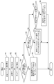
図3を参照して、フローの定義情報を設定した後の情報の収集及び構成変更の契機について説明する。
OFC23は、OFS121(121-i、i=1~x)から情報を収集し、フロー数をカウントし、各フローをサービス管理部24に通知する。
サービス管理部24は、該当フローをサービス毎に分類し、サービス毎の単位時間当たりのサービス数として情報を保持する。
サービス管理部24は、サービス数を監視し、サービス数の変化を契機として、以下のようにサービスの論理構成・物理構成の変更を行うように、仮想マシン管理部27に指示する。
仮想マシン管理部27は、サービス数が所定の閾値以上となった場合、所定の閾値より小さくなるように当該サービス数を軽減するための処理を行う。なお、ここでいう所定の閾値は、上限閾値でも良い。例えば、「(サービス数) ≧ (1つのVMで負担できるサービス数) × (VM数)」となった場合、仮想マシン管理部27は、当該サーバにおいてサービスへ割り当てるVMを増加させる。すなわち、当該サーバ上で当該サービス用のVMの稼動処理を行う。
仮想マシン管理部27は、サービス数が所定の閾値より小さくなった場合、所定の閾値以下の範囲内でサービス数を増大させるための処理を行う。なお、ここでいう所定の閾値は、下限閾値でも良い。例えば、「(サービス数) < (1つのVMで負担できるサービス数) × (VM数)」となった場合、仮想マシン管理部27は、当該サーバにおいてサービスからVMを削減させる。すなわち、当該サーバ上で当該サービス用のVMの停止処理を行う。
ここでは、VMを移動することにより更なる省電力化を目指す稼動リソース最適化処理を記述する。この処理は、VM停止処理の終了を契機として動作する。なお、実際には、VMを停止せずに最適化のみを行っても構わない。その場合の契機としては、システム全体の負荷が閾値を超過した場合等が考えられる。なお、ここでいう閾値は、上限閾値と下限閾値で囲まれた一定の範囲に収まる値の集合でも良い。この場合、閾値を超過した場合とは、上限閾値と下限閾値で囲まれた一定の範囲に収まらない値であることを意味する。
統合管理部21は、以下の数式(1)を用いて、必要リソース量の算出を行う。

統合管理部21は、以下の数式(2)を用いて、必要サーバ数の算出を行う。

統合管理部21は、停止サーバ数Tを算出する。停止サーバ数Tは、稼動サーバ数をCとすると、T=C-Sとなる。
統合管理部21は、停止可能空調グループの検索を行う。説明の簡略化のため、便宜上、空調グループを対象とする場合を例に説明しているが、照明グループや電源グループを対象とする場合も基本的に同様である。すなわち、「空調」を、「照明」や「電源」と読み替えることも可能である。
統合管理部21は、サーバ管理部25及び仮想マシン管理部27に指示して、停止可能空調グループから停止しない他の空調グループへVMをマイグレーションする。統合管理部21は、停止可能空調グループの停止に伴い停止するサーバの台数をX台とした場合、現在の停止サーバ数TからXを減じ、残りの停止サーバ数をT-Xへ変更する。従って、残りの停止サーバ数T=現在の停止サーバ数T-停止するサーバの台数Xとなる。
統合管理部21は、停止可能ラックグループの検索を行う。具体的には、統合管理部21は、T台以内のサーバを停止することでラックが停止するラックグループを検索する。従って、停止可能ラックグループで稼働中のサーバの合計台数は、T台以内であるものとする。統合管理部21は、停止可能ラックグループがあった場合、当該ラックグループを停止することを決定する。なお、統合管理部21は、停止するラックグループがなかった場合、停止可能サーバの検索処理(ステップR8)へ移行する。
統合管理部21は、サーバ管理部25及び仮想マシン管理部27に指示して、停止対象ラックグループから停止しない他のラックグループへVMをマイグレーションする。統合管理部21は、停止可能ラックグループの停止に伴い停止するサーバの台数をY台とした場合、現在の停止サーバ数TからYを減じ、残りの停止サーバ数をT-Yへ変更する。従って、残りの停止サーバ数T=現在の停止サーバ数T-停止するサーバの台数Yとなる。
統合管理部21は、停止可能サーバの検索を行う。具体的には、統合管理部21は、ラック内の稼動サーバ数が最小となるラックグループを検索する。統合管理部21は、停止するT台のサーバ群を決定する。従って、停止可能サーバの合計台数は、T台以内であるものとする。統合管理部21は、停止可能サーバがあった場合、当該サーバを停止することを決定する。
統合管理部21は、サーバ管理部25及び仮想マシン管理部27に指示して、停止対象サーバからVMをマイグレーションする。具体的には、統合管理部21は、停止することを決定したサーバ上の全VMについて、移動先サーバを決定する。移動先サーバの例として、各VMが属するサービスの使用するストレージに接続できるサーバ、停止予定以外のサーバ、VMが必要とするリソースを持つサーバ、等が考えられる。統合管理部21は、サーバ管理部25及び仮想マシン管理部27に指示して、決定したサーバに各VMをマイグレーションする。統合管理部21は、サーバ管理部25及び仮想マシン管理部27に指示して、サーバを停止し、ラックグループ中のサーバの状態を未稼働とする。
なお、ラック間の接続に関しては、下記の制限を満たすことが望ましい。
・ラック間の相互接続を可能な限りなくす
・空調グループ単位で相互接続用スイッチを設ける
・空調グループ間の接続を常時稼動のスイッチラックで行う
統合管理部21は、OFC23に指示して、下記処理を追加することで、稼動OFS数を更に減少させることができる。
図5を参照して、移動先サーバの決定処理について説明する。なお、統合管理部21は、ラック停止後のトポロジー情報を経路算出に使用することを前提とする。
統合管理部21は、未使用リソースがあるサーバをリストアップする。
統合管理部21は、マイグレーション対象のVMをリストアップする。
統合管理部21は、リストアップされたVMの中から、未移動のVMを1つ選択する。
統合管理部21は、リストアップされたサーバの中から、所定の条件に適合するサーバを選択する。具体的には、統合管理部21は、選択された未移動のVMが含まれるサービスが使用するストレージと接続可能であり、サービスの他のVM及び外部ネットワークと通信経路が確立できるサーバを選択する。
統合管理部21は、選択されたサーバにVMが使用する未使用リソースがあるか確認する。統合管理部21は、選択されたサーバにVMが使用する未使用リソースがある場合、選択された未稼働のVMを該当サーバに仮割り当てし、同時に未使用リソースを予約する。統合管理部21は、移動先が決定していないVMがあれば、再度、未移動のVMを1つ選択する。
統合管理部21は、選択されたサーバに仮割り当てされたVMのうち、他の未使用リソースがあるサーバに移動可能なVMを検索する。統合管理部21は、他の未使用リソースがあるサーバに移動可能なVMがある場合、VMの仮割り当て先を変更し、同時に使用リソースの開放と新規仮割り当て先に予約する。統合管理部21は、選択された未稼働のVMが仮割り当てされたサーバに仮割り当てし、同時に未使用リソースを予約する。統合管理部21は、移動先が決定していないVMがあれば、再度、未移動のVMを1つ選択する。ここでは、VMの移動先を仮割り当てで一旦予約し、その後、未使用リソースが最小になるように変更することを考えている。
統合管理部21は、動作中のVMのうち、他の未使用リソースがあるサーバに移動可能なVMを検索する。統合管理部21は、他の未使用リソースがあるサーバに移動可能なものがある場合、VMを移動対象とし、仮割り当て先を設定し、同時に使用リソースの開放と新規仮割り当て先に予約する。統合管理部21は、選択された未移動のVMが仮割り当てされたサーバに仮割り当てし、同時に未使用リソースを予約する。統合管理部21は、移動先が決定していないVMがあれば、再度、未移動のVMを1つ選択する。統合管理部21は、他の未使用リソースがあるサーバに移動可能なVMがない場合、選択された未移動のVMを保留とする。
統合管理部21は、移動先が決定していないVMがあれば、再度、未移動のVMを1つ選択する。
統合管理部21は、各VMの仮割り当てしたサーバをマイグレーション先として決定する。
次に、「管理者による手動VM起動停止を契機とした省電力化」に係る処理について、構成変更の契機、起動処理、停止処理の3つに分けて説明する。
統合管理部21は、管理者により、サービス毎のVM数が変更された場合、次のように処理する。例えば、統合管理部21は、管理者によりサービスにVMが追加された場合、必要なサーバやVMの稼動処理を行う。また、統合管理部21は、管理者によりサービスからVMが削減された場合、不要なサーバやVMの停止処理を行う。
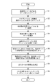
図6を参照して、稼動処理について説明する。
統合管理部21は、管理者により、サービスと追加VM数が指定され、稼動処理の開始が指示される。統合管理部21は、稼動中のサーバの中から、条件に適合するサーバを検索する処理を開始する。
統合管理部21は、稼動中のサーバの中に、条件に適合するサーバがあるか確認する。
統合管理部21は、稼動中のサーバの中に、条件に適合するサーバがない場合、稼働中のラックの中に、未稼働のサーバがあるか確認する。
統合管理部21は、稼働中のラックの中に、未稼働のサーバがない場合、稼働中の空調グループの中に、未稼働のラックがあるか確認する。
統合管理部21は、稼働中の空調グループの中に、未稼働のラックがない場合、未稼働の空調グループを稼動させる。
統合管理部21は、稼働中の空調グループの中に、未稼働のラックがある場合、未稼働のラックを稼動させる。
統合管理部21は、稼働中のラックの中に、未稼働のサーバがある場合、未稼働のサーバを稼動させる。その後、統合管理部21は、稼動中のサーバの中から条件に適合するサーバを検索する処理(ステップA1)に戻り、同様の処理を繰り返す。
統合管理部21は、稼動中のサーバの中に、条件に適合するサーバがある場合、条件に適合するサーバに、指定されたサービスのVMを割り当てる。
統合管理部21は、未割り当てのVMがあるか確認する。すなわち、統合管理部21は、条件に適合するサーバに、指定された数のVMを全て割り当て、条件に適合するサーバ上で指定された数のVMを稼動することができたか確認する。
図7を参照して、停止処理について説明する。
管理者より、統合管理部21に、サービスと停止VM数が指定され、稼動処理の開始が指示される。これにより、統合管理部21は、処理を開始する。
統合管理部21は、サービス構成情報とラック情報と空調情報から指定されたVM群のうち、停止するVMを選択し、決定する。
VMの選択の優先度の例として、以下の順序に従って選択することが考えられる。
1.当該VMを停止することで、サーバが停止でき、ラックが停止でき、空調も停止できるVM
2.当該VMを停止することで、サーバが停止でき、ラックが停止できるVM
3.当該VMを停止することで、サーバが停止できるVM
4.当該VMを停止することで、サーバ中の稼動VM数が最小となるVM
統合管理部21は、仮想マシン管理部27に指示して、片寄を行い停止するVMに処理がこないようにする。
統合管理部21は、仮想マシン管理部27に指示して、VMで全処理が終了したら、VMを停止し、サービスの稼動VM数を減少させる。
統合管理部21は、サーバ管理部25に指示して、該当サーバの削除したVMの分使用可能リソースを増加させる。
統合管理部21は、サーバ管理部25に指示して、移動VMがなくなったサーバが発生した場合、サーバを停止し、該当ラックグループの該当サーバの状態を未稼動とする。
統合管理部21は、サーバ停止の波及効果を調査する。
更に、他の停止処理について検討する。
統合管理部21は、OFC23に指示して、停止処理の終了後に他のOFSを未稼動にできないかを調査することで、未稼働リソースを増やすことも可能である。例えば、以下の3つの方法が考えられる。
なお、本発明において、ストレージのアクセス制限を考慮すると、統合管理部21は、VM起動(稼動)時、或いは、VMマイグレーション時に、ストレージ管理部26と連携し、ストレージに適切なアクセス制限を設定する必要があると考えられる。
また、本発明において、上記のサービス数の代わりに、サービスに応じたネットワークにおける通信負荷やサーバにおける処理負荷をサービス負荷とし、このサービス負荷の変化を契機として、サーバの論理構成・物理構成の変更を行うようにすることも考えられる。

上記の実施形態の一部又は全部は、以下の付記のように記載することも可能である。但し、実際には、以下の記載例に限定されない。
複数のサーバ上でそれぞれ稼動する仮想マシンにより提供されるサービスの通信情報を監視するステップと、
前記通信情報から求められた仮想マシン毎のサービス負荷を基に、仮想マシンを他のサーバ上へ移動させ、稼動する仮想マシンが存在しなくなったサーバを未稼動状態にするステップと、
前記サービスの通信パケットの転送を行うスイッチに対してフロー単位の経路情報を設定するステップと、
仮想マシンの移動に従って前記スイッチに対して設定した経路情報を変更するステップと
をコンピュータに実行させるための省電力化プログラムを記憶した
記憶媒体。
付記1に記載の記憶媒体であって、
前記サービスに応じたネットワークにおける通信負荷及び前記サービスに応じたサーバにおける処理負荷に基づいて、前記サービス負荷を求めるステップ
を更にコンピュータに実行させるための省電力化プログラムを記憶した
記憶媒体。
付記1又は2に記載の記憶媒体であって、
前記仮想マシンの移動に伴って前記スイッチの経路情報が変更された結果、稼動不要なスイッチが存在すれば、当該スイッチを未稼動状態にするステップ
を更にコンピュータに実行させるための省電力化プログラムを記憶した
記憶媒体。
付記1乃至3のいずれかに記載の記憶媒体であって、
前記スイッチ及び前記複数のサーバを格納したラック内のサーバ上で稼動する仮想マシンを他のラック内のサーバ上へ移動させるステップと、
当該ラック外のスイッチを経由するように前記スイッチに設定された経路情報を変更するステップと、
前記スイッチ及び前記複数のサーバをコンピュータに実行させるための省電力化プログラムを記憶した当該ラック全体を未稼動状態にするステップと
を更にコンピュータに実行させるための省電力化プログラムを記憶した
記憶媒体。
付記4に記載の記憶媒体であって、
ラックの周辺環境状態を調整する設備を制御し、前記未稼動状態となったラックの周辺環境状態の調整を変化または停止させるステップ
を更にコンピュータに実行させるための省電力化プログラムを記憶した
記憶媒体。
付記5に記載の記憶媒体であって、
前記設備による周辺環境状態の制御対象となっているラック群単位で未稼動状態にするステップが可能な対象を探索し、次に、ラック単位、サーバ単位の順に未稼動状態にするステップが可能な対象を順に探索するステップ
を更にコンピュータに実行させるための省電力化プログラムを記憶した
記憶媒体。
付記4又は5に記載の記憶媒体であって、
空調の対象となる空調グループに属するラックを冷却する空調設備を制御し、前記空調グループに属する全てのラックが未稼働状態になった場合、前記空調設備による冷却を調節または停止させるステップと、
照明の対象となる照明グループに属するラックを照らす照明設備を制御し、前記照明グループに属する全てのラックが未稼働状態になった場合、前記照明設備による照明を調節または停止させるステップと、
電源の対象となる電源グループに属するラックに配電する電源設備を制御し、前記電源グループに属する全てのラックが未稼働状態になった場合、前記電源設備による配電を調節または停止させるステップと
を更にコンピュータに実行させるための省電力化プログラムを記憶した
記憶媒体。
Claims (16)
- 複数のサーバ上でそれぞれ稼動する仮想マシンにより提供されるサービスの通信情報を監視し、前記通信情報から求められた仮想マシン毎のサービス負荷を基に、仮想マシンを他のサーバ上へ移動させ、稼動する仮想マシンが存在しなくなったサーバを未稼動状態にする管理装置と、
前記サービスの通信パケットの転送を行うスイッチに対してフロー単位の経路情報を設定するコントローラと
を具備し、
前記コントローラは、仮想マシンの移動に従って前記スイッチに対して設定した経路情報を変更する
省電力化システム。 - 請求項1に記載の省電力化システムであって、
前記管理装置は、前記サービスに応じたネットワークにおける通信負荷及び前記サービスに応じたサーバにおける処理負荷に基づいて、前記サービス負荷を求める
省電力化システム。 - 請求項1又は2に記載の省電力化システムであって、
前記管理装置は、仮想マシンの移動に伴って前記スイッチの経路情報が変更された結果、稼動不要なスイッチが存在すれば、当該スイッチを未稼動状態にする
省電力化システム。 - 請求項1乃至3のいずれか一項に記載の省電力化システムであって、
前記スイッチ及び前記複数のサーバは、ラック内に格納され、
前記管理装置は、当該ラック内のサーバ上で稼動する仮想マシンを他のラック内のサーバ上へ移動させ、
前記コントローラは、当該ラック外のスイッチを経由するように前記スイッチに設定された経路情報を変更し、
前記管理装置は、前記スイッチ及び前記複数のサーバを含む当該ラック全体を未稼動状態にする
省電力化システム。 - 請求項4に記載の省電力化システムであって、
前記管理装置は、ラックの周辺環境状態を調整する設備を制御し、前記未稼動状態となったラックの周辺環境状態の調整を変化または停止させる
省電力化システム。 - 請求項5に記載の省電力化システムであって、
前記管理装置は、前記設備による周辺環境状態の制御対象となっているラック群単位で未稼動状態にすることが可能な対象を探索し、次に、ラック単位、サーバ単位の順に未稼動状態にすることが可能な対象を順に探索する
省電力化システム。 - 請求項5又は6に記載の省電力化システムであって、
前記管理装置は、
空調の対象となる空調グループに属するラックを冷却する空調設備を制御し、前記空調グループに属する全てのラックが未稼働状態になった場合、前記空調設備による冷却を調節または停止させる空調設備管理部と、
照明の対象となる照明グループに属するラックを照らす照明設備を制御し、前記照明グループに属する全てのラックが未稼働状態になった場合、前記照明設備による照明を調節または停止させる照明設備管理部と、
電源の対象となる電源グループに属するラックに配電する電源設備を制御し、前記電源グループに属する全てのラックが未稼働状態になった場合、前記電源設備による配電を調節または停止させる電源設備管理部と
を具備する
省電力化システム。 - 請求項1乃至7のいずれか一項に記載の省電力化システムで、管理装置及びコントローラのうち少なくとも一方として使用されるコンピュータ。
- コンピュータにより実施される省電力化方法であって、
複数のサーバ上でそれぞれ稼動する仮想マシンにより提供されるサービスの通信情報を監視することと、
前記通信情報から求められた仮想マシン毎のサービス負荷を基に、仮想マシンを他のサーバ上へ移動させ、稼動する仮想マシンが存在しなくなったサーバを未稼動状態にすることと、
前記サービスの通信パケットの転送を行うスイッチに対してフロー単位の経路情報を設定することと、
仮想マシンの移動に従って前記スイッチに対して設定した経路情報を変更することと
を含む
省電力化方法。 - 請求項9に記載の省電力化方法であって、
前記サービスに応じたネットワークにおける通信負荷及び前記サービスに応じたサーバにおける処理負荷に基づいて、前記サービス負荷を求めること
を更に含む
省電力化方法。 - 請求項9又は10に記載の省電力化方法であって、
前記仮想マシンの移動に伴って前記スイッチの経路情報が変更された結果、稼動不要なスイッチが存在すれば、当該スイッチを未稼動状態にすること
を更に含む
省電力化方法。 - 請求項9乃至11のいずれか一項に記載の省電力化方法であって、
前記スイッチ及び前記複数のサーバを格納したラック内のサーバ上で稼動する仮想マシンを他のラック内のサーバ上へ移動させることと、
当該ラック外のスイッチを経由するように前記スイッチに設定された経路情報を変更することと、
前記スイッチ及び前記複数のサーバを含む当該ラック全体を未稼動状態にすることと
を更に含む
省電力化方法。 - 請求項12に記載の省電力化方法であって、
ラックの周辺環境状態を調整する設備を制御し、前記未稼動状態となったラックの周辺環境状態の調整を変化または停止させること
を更に含む
省電力化方法。 - 請求項13に記載の省電力化方法であって、
前記設備による周辺環境状態の制御対象となっているラック群単位で未稼動状態にすることが可能な対象を探索し、次に、ラック単位、サーバ単位の順に未稼動状態にすることが可能な対象を順に探索すること
を更に含む
省電力化方法。 - 請求項13又は14に記載の省電力化方法であって、
空調の対象となる空調グループに属するラックを冷却する空調設備を制御し、前記空調グループに属する全てのラックが未稼働状態になった場合、前記空調設備による冷却を調節または停止させることと、
照明の対象となる照明グループに属するラックを照らす照明設備を制御し、前記照明グループに属する全てのラックが未稼働状態になった場合、前記照明設備による照明を調節または停止させることと、
電源の対象となる電源グループに属するラックに配電する電源設備を制御し、前記電源グループに属する全てのラックが未稼働状態になった場合、前記電源設備による配電を調節または停止させることと
を更に含む
省電力化方法。 - 請求項9乃至15のいずれか一項に記載の省電力化方法をコンピュータに実行させるための省電力化プログラムを記憶した記憶媒体。
Priority Applications (3)
| Application Number | Priority Date | Filing Date | Title |
|---|---|---|---|
| US13/499,903 US20120204051A1 (en) | 2009-10-07 | 2010-10-05 | Power saving system and power saving method |
| CN201080045377.9A CN102549973B (zh) | 2009-10-07 | 2010-10-05 | 功率节省系统及功率节省方法 |
| EP10821987.4A EP2487837A4 (en) | 2009-10-07 | 2010-10-05 | ENERGY SAVING SYSTEM AND ENERGY SAVING METHOD |
Applications Claiming Priority (2)
| Application Number | Priority Date | Filing Date | Title |
|---|---|---|---|
| JP2009-233366 | 2009-10-07 | ||
| JP2009233366A JP5435399B2 (ja) | 2009-10-07 | 2009-10-07 | 省電力化システム、省電力化方法、及び省電力化用プログラム |
Publications (1)
| Publication Number | Publication Date |
|---|---|
| WO2011043317A1 true WO2011043317A1 (ja) | 2011-04-14 |
Family
ID=43856770
Family Applications (1)
| Application Number | Title | Priority Date | Filing Date |
|---|---|---|---|
| PCT/JP2010/067414 WO2011043317A1 (ja) | 2009-10-07 | 2010-10-05 | 省電力化システム、及び省電力化方法 |
Country Status (5)
| Country | Link |
|---|---|
| US (1) | US20120204051A1 (ja) |
| EP (1) | EP2487837A4 (ja) |
| JP (1) | JP5435399B2 (ja) |
| CN (1) | CN102549973B (ja) |
| WO (1) | WO2011043317A1 (ja) |
Cited By (7)
| Publication number | Priority date | Publication date | Assignee | Title |
|---|---|---|---|---|
| US20120331147A1 (en) * | 2011-06-23 | 2012-12-27 | Cisco Technology, Inc. | Hierarchical defragmentation of resources in data centers |
| CN102893229A (zh) * | 2011-12-29 | 2013-01-23 | 华为技术有限公司 | 一种节能监控方法以及设备 |
| JP2013516823A (ja) * | 2010-01-04 | 2013-05-13 | アルカテル−ルーセント | 通信ネットワーク内のカードをアクティブ化するための方法 |
| CN103309421A (zh) * | 2012-03-08 | 2013-09-18 | 株式会社日立制作所 | 外部空气冷却以及局部冷却方式信息处理系统和其负荷分配方法 |
| WO2013164917A1 (ja) * | 2012-05-02 | 2013-11-07 | 株式会社エヌ・ティ・ティ・ドコモ | 移動体通信システム、呼処理ノード及び通信制御方法 |
| CN104468181A (zh) * | 2013-09-23 | 2015-03-25 | 英特尔公司 | 虚拟网络设备故障的检测和处理 |
| US9110730B2 (en) | 2011-08-25 | 2015-08-18 | Fujitsu Limited | Communication method and communication apparatus |
Families Citing this family (50)
| Publication number | Priority date | Publication date | Assignee | Title |
|---|---|---|---|---|
| JP5402688B2 (ja) * | 2010-02-02 | 2014-01-29 | 日本電気株式会社 | パケット転送システム、パケット転送システム内におけるパケット集中回避方法 |
| WO2012070173A1 (en) * | 2010-11-22 | 2012-05-31 | Nec Corporation | Communication system, communication device, controller, and method and program for controlling forwarding path of packet flow |
| FR2974647B1 (fr) * | 2011-04-26 | 2013-04-26 | Bull Sas | Dispositif de reperage pour reperer une armoire informatique parmi une pluralite d'armoires informatiques |
| JP5576827B2 (ja) * | 2011-06-03 | 2014-08-20 | 日本電信電話株式会社 | サーバ管理システム、サーバ管理装置、サーバ管理方法、及びサーバ管理プログラム |
| WO2013011894A1 (ja) * | 2011-07-20 | 2013-01-24 | 日本電気株式会社 | ユーザ共有型データセンタシステム |
| ITRM20110433A1 (it) | 2011-08-10 | 2013-02-11 | Univ Calabria | Sistema per il risparmio di energia nei data center aziendali. |
| US8825863B2 (en) * | 2011-09-20 | 2014-09-02 | International Business Machines Corporation | Virtual machine placement within a server farm |
| WO2013042271A1 (ja) * | 2011-09-22 | 2013-03-28 | 富士通株式会社 | 電子計算機システム及び仮想マシン配置方法 |
| WO2013042269A1 (ja) * | 2011-09-22 | 2013-03-28 | 富士通株式会社 | 電源管理装置、電源管理方法および電源管理プログラム |
| US8824143B2 (en) * | 2011-10-12 | 2014-09-02 | International Business Machines Corporation | Combined power and cooling rack supporting an electronics rack(S) |
| CN103138940B (zh) * | 2011-11-28 | 2016-06-01 | 英业达科技有限公司 | 服务器机架系统 |
| CN103138942B (zh) * | 2011-11-28 | 2015-09-02 | 英业达科技有限公司 | 服务器机架系统 |
| JP5750714B2 (ja) * | 2012-01-19 | 2015-07-22 | 株式会社日立製作所 | 計算機システム、仮想サーバ配置方法及び配置制御装置 |
| EP2811403A4 (en) | 2012-02-03 | 2015-10-07 | Fujitsu Ltd | CONTROL PROGRAM FOR A VIRTUAL MACHINE, VIRTUAL MACHINE CONTROL METHOD AND INFORMATION PROCESSING DEVICE |
| JP5881465B2 (ja) * | 2012-02-27 | 2016-03-09 | 株式会社日立製作所 | 管理計算機、転送経路管理方法及び計算機システム |
| US20150063361A1 (en) * | 2012-03-28 | 2015-03-05 | Nec Corporation | Computer system and communication route changing method |
| JP5983782B2 (ja) * | 2012-06-12 | 2016-09-06 | 日本電気株式会社 | コンピュータシステム、通信制御サーバ、通信制御方法およびプログラム |
| JP2014006792A (ja) * | 2012-06-26 | 2014-01-16 | Ntt Comware Corp | 通信制御装置、通信制御方法、通信制御プログラム |
| CN102769670A (zh) * | 2012-07-13 | 2012-11-07 | 中兴通讯股份有限公司 | 虚拟机迁移方法、装置及系统 |
| JP6299754B2 (ja) * | 2012-09-13 | 2018-03-28 | 日本電気株式会社 | 制御装置、制御方法、通信システム及びプログラム |
| US9178715B2 (en) | 2012-10-01 | 2015-11-03 | International Business Machines Corporation | Providing services to virtual overlay network traffic |
| CN103777734A (zh) * | 2012-10-25 | 2014-05-07 | 英业达科技有限公司 | 机柜式服务器系统与其操作方法 |
| CN103067476B (zh) * | 2012-12-25 | 2015-08-19 | 浙江大学 | 一种基于虚拟机的动态网络重构方法 |
| JP5978993B2 (ja) * | 2012-12-28 | 2016-08-24 | 富士通株式会社 | 情報処理システム制御装置、該プログラム、及び該方法 |
| EP2755135B1 (en) | 2013-01-14 | 2016-07-13 | Fujitsu Limited | Computing device, method, and program for energy-efficient distribution of computational load |
| US9201706B2 (en) * | 2013-03-11 | 2015-12-01 | International Business Machines Corporation | Minimizing workload migrations during cloud maintenance operations |
| US9933832B2 (en) * | 2013-03-14 | 2018-04-03 | Vmware, Inc. | Systems and methods for modifying power states in a virtual environment |
| JP6076164B2 (ja) * | 2013-03-22 | 2017-02-08 | 京セラ株式会社 | 制御システム、機器、制御装置及び制御方法 |
| WO2014156485A1 (ja) | 2013-03-29 | 2014-10-02 | 株式会社サイバー・ソリューションズ | グリーンネットワーク構築方法 |
| CN103345298B (zh) * | 2013-07-16 | 2015-07-01 | 山东省计算中心(国家超级计算济南中心) | 一种基于虚拟it资源分配技术的数据中心节能系统的方法 |
| US9625974B2 (en) * | 2013-12-23 | 2017-04-18 | Dell Products, L.P. | Global throttling of computing nodes in a modular, rack-configured information handling system |
| JP2015197892A (ja) * | 2014-04-03 | 2015-11-09 | 河村電器産業株式会社 | データセンタ節電システム |
| US9887939B2 (en) | 2015-03-11 | 2018-02-06 | International Business Machines Corporation | Transmitting multi-destination packets in overlay networks |
| JP6532526B2 (ja) | 2014-05-30 | 2019-06-19 | 華為技術有限公司Huawei Technologies Co.,Ltd. | ネットワーク制御方法及び装置 |
| CN104052665B (zh) * | 2014-06-03 | 2019-03-15 | 新华三技术有限公司 | 一种流量转发路径的确定方法和设备 |
| JP6260470B2 (ja) | 2014-06-26 | 2018-01-17 | 富士通株式会社 | 網監視システムおよび網監視方法 |
| JP6267606B2 (ja) * | 2014-09-01 | 2018-01-24 | 日本電信電話株式会社 | ネットワークシステム、仮想化方法および仮想化プログラム |
| US9886083B2 (en) * | 2014-12-19 | 2018-02-06 | International Business Machines Corporation | Event-driven reoptimization of logically-partitioned environment for power management |
| JP6430892B2 (ja) * | 2015-05-14 | 2018-11-28 | 株式会社Nttファシリティーズ | 給電システム、給電方法およびサーバ |
| JP6420212B2 (ja) * | 2015-06-25 | 2018-11-07 | 株式会社Nttファシリティーズ | 統合型設備管理システム |
| US9874924B1 (en) * | 2015-12-03 | 2018-01-23 | Amazon Technologies, Inc. | Equipment rack power reduction using virtual machine instance migration |
| US10469570B2 (en) * | 2015-12-26 | 2019-11-05 | Intel Corporation | Technologies for execution acceleration in heterogeneous environments |
| JP6202124B2 (ja) * | 2016-03-23 | 2017-09-27 | 日本電気株式会社 | サーバ装置、サーバ制御方法、プログラム |
| US10728084B2 (en) * | 2016-04-11 | 2020-07-28 | Quanta Computer Inc. | Virtualized rack management modules |
| US10411499B2 (en) * | 2017-05-05 | 2019-09-10 | David R. Hall | Distributed charge controller |
| US10782757B2 (en) * | 2017-08-09 | 2020-09-22 | Equinix, Inc. | Rack level power control |
| JP6939327B2 (ja) * | 2017-09-25 | 2021-09-22 | 富士フイルムビジネスイノベーション株式会社 | プログラム及び情報処理装置 |
| CN110086676B (zh) * | 2019-05-08 | 2022-11-22 | 深信服科技股份有限公司 | 一种分布式路由器的配置方法及相关设备 |
| JPWO2022153346A1 (ja) * | 2021-01-12 | 2022-07-21 | ||
| WO2023157168A1 (ja) * | 2022-02-17 | 2023-08-24 | 日本電信電話株式会社 | 通信システム、統合コントローラ及び切替方法 |
Citations (7)
| Publication number | Priority date | Publication date | Assignee | Title |
|---|---|---|---|---|
| JP2003281008A (ja) | 2002-03-26 | 2003-10-03 | Toshiba Corp | サーバー計算機負荷分配装置、サーバー計算機負荷分配方法、サーバー計算機負荷分配プログラム及びサーバー計算機システム |
| JP2007189848A (ja) * | 2006-01-16 | 2007-07-26 | Hitachi Ltd | 電源自動制御システム |
| JP2008276320A (ja) * | 2007-04-25 | 2008-11-13 | Nec Corp | 仮想システム制御方法およびコンピュータシステム |
| JP2009169858A (ja) | 2008-01-18 | 2009-07-30 | Nec Corp | サーバシステム、及びサーバシステムの電力削減方法 |
| JP2009176033A (ja) | 2008-01-24 | 2009-08-06 | Hitachi Ltd | ストレージシステム及びその消費電力削減方法 |
| JP2009181571A (ja) | 2007-12-28 | 2009-08-13 | Intel Corp | 大規模データセンターまたはitインフラにおけるエネルギー消費の確定および動的制御方法 |
| JP2009233366A (ja) | 2009-07-15 | 2009-10-15 | Kyushu Hitachi Maxell Ltd | ヘアードライヤー |
Family Cites Families (8)
| Publication number | Priority date | Publication date | Assignee | Title |
|---|---|---|---|---|
| ATE525829T1 (de) * | 2005-02-28 | 2011-10-15 | Ibm | Bladeserversystem mit mindestens einem stapelschalter mit mehreren untereinander verbundenen und für verwaltung sowie betrieb als virtueller einzelschalter konfigurierten schaltern |
| JP4895266B2 (ja) * | 2005-12-28 | 2012-03-14 | 富士通株式会社 | 管理システム、管理プログラムおよび管理方法 |
| US8296760B2 (en) * | 2006-10-27 | 2012-10-23 | Hewlett-Packard Development Company, L.P. | Migrating a virtual machine from a first physical machine in response to receiving a command to lower a power mode of the first physical machine |
| US8385202B2 (en) * | 2008-08-27 | 2013-02-26 | Cisco Technology, Inc. | Virtual switch quality of service for virtual machines |
| US20100287262A1 (en) * | 2009-05-08 | 2010-11-11 | Uri Elzur | Method and system for guaranteed end-to-end data flows in a local networking domain |
| JP5190084B2 (ja) * | 2010-03-30 | 2013-04-24 | 株式会社日立製作所 | 仮想マシンのマイグレーション方法およびシステム |
| US8239863B2 (en) * | 2010-06-29 | 2012-08-07 | Hewlett-Packard Development Company, L.P. | Method and system for migrating a virtual machine |
| US8423646B2 (en) * | 2010-07-09 | 2013-04-16 | International Business Machines Corporation | Network-aware virtual machine migration in datacenters |
-
2009
- 2009-10-07 JP JP2009233366A patent/JP5435399B2/ja not_active Expired - Fee Related
-
2010
- 2010-10-05 WO PCT/JP2010/067414 patent/WO2011043317A1/ja active Application Filing
- 2010-10-05 CN CN201080045377.9A patent/CN102549973B/zh active Active
- 2010-10-05 EP EP10821987.4A patent/EP2487837A4/en not_active Withdrawn
- 2010-10-05 US US13/499,903 patent/US20120204051A1/en not_active Abandoned
Patent Citations (7)
| Publication number | Priority date | Publication date | Assignee | Title |
|---|---|---|---|---|
| JP2003281008A (ja) | 2002-03-26 | 2003-10-03 | Toshiba Corp | サーバー計算機負荷分配装置、サーバー計算機負荷分配方法、サーバー計算機負荷分配プログラム及びサーバー計算機システム |
| JP2007189848A (ja) * | 2006-01-16 | 2007-07-26 | Hitachi Ltd | 電源自動制御システム |
| JP2008276320A (ja) * | 2007-04-25 | 2008-11-13 | Nec Corp | 仮想システム制御方法およびコンピュータシステム |
| JP2009181571A (ja) | 2007-12-28 | 2009-08-13 | Intel Corp | 大規模データセンターまたはitインフラにおけるエネルギー消費の確定および動的制御方法 |
| JP2009169858A (ja) | 2008-01-18 | 2009-07-30 | Nec Corp | サーバシステム、及びサーバシステムの電力削減方法 |
| JP2009176033A (ja) | 2008-01-24 | 2009-08-06 | Hitachi Ltd | ストレージシステム及びその消費電力削減方法 |
| JP2009233366A (ja) | 2009-07-15 | 2009-10-15 | Kyushu Hitachi Maxell Ltd | ヘアードライヤー |
Non-Patent Citations (3)
| Title |
|---|
| BRANDON HELLER: "OpenFlow Switch Specification Version 0.9.0 (Wire Protocol 0x98", CURRENT MAINTAINER, 20 July 2009 (2009-07-20), Retrieved from the Internet <URL:http://www.openflowswitch.org/documents/openflow-spec- v0,9.0.pdf> |
| NEC CORP.: "Shin Sedai NW ni Muketa Programmable Flow Switch o Shisaku shi Nichibei-kan deno Jissho Jikken ni Seiko", PRESS RELEASE NEC [ONLINE], 29 October 2008 (2008-10-29), XP008153121, Retrieved from the Internet <URL:http://www.nec.co.jp/press/ja/0810/2903.html> [retrieved on 20101217] * |
| See also references of EP2487837A4 |
Cited By (17)
| Publication number | Priority date | Publication date | Assignee | Title |
|---|---|---|---|---|
| JP2013516823A (ja) * | 2010-01-04 | 2013-05-13 | アルカテル−ルーセント | 通信ネットワーク内のカードをアクティブ化するための方法 |
| US20120331147A1 (en) * | 2011-06-23 | 2012-12-27 | Cisco Technology, Inc. | Hierarchical defragmentation of resources in data centers |
| US8914513B2 (en) * | 2011-06-23 | 2014-12-16 | Cisco Technology, Inc. | Hierarchical defragmentation of resources in data centers |
| US9110730B2 (en) | 2011-08-25 | 2015-08-18 | Fujitsu Limited | Communication method and communication apparatus |
| CN102893229A (zh) * | 2011-12-29 | 2013-01-23 | 华为技术有限公司 | 一种节能监控方法以及设备 |
| WO2013097134A1 (zh) * | 2011-12-29 | 2013-07-04 | 华为技术有限公司 | 一种节能监控方法以及设备 |
| US9917704B2 (en) | 2011-12-29 | 2018-03-13 | Huawei Technologies Co., Ltd. | Energy saving monitoring method and device |
| EP2712122A1 (en) * | 2011-12-29 | 2014-03-26 | Huawei Technologies Co., Ltd | Energy saving monitoring method and device |
| EP2712122A4 (en) * | 2011-12-29 | 2014-07-23 | Huawei Tech Co Ltd | MONITORING PROCESS AND DEVICE FOR ENERGY SAVING |
| US9411344B2 (en) | 2011-12-29 | 2016-08-09 | Huawei Technologies Co., Ltd. | Energy saving monitoring method and device |
| CN103309421A (zh) * | 2012-03-08 | 2013-09-18 | 株式会社日立制作所 | 外部空气冷却以及局部冷却方式信息处理系统和其负荷分配方法 |
| WO2013164917A1 (ja) * | 2012-05-02 | 2013-11-07 | 株式会社エヌ・ティ・ティ・ドコモ | 移動体通信システム、呼処理ノード及び通信制御方法 |
| JP2015062282A (ja) * | 2013-09-23 | 2015-04-02 | インテル・コーポレーション | 仮想ネットワークアプライアンス不良の検知及びハンドリング |
| US9350632B2 (en) | 2013-09-23 | 2016-05-24 | Intel Corporation | Detection and handling of virtual network appliance failures |
| CN104468181A (zh) * | 2013-09-23 | 2015-03-25 | 英特尔公司 | 虚拟网络设备故障的检测和处理 |
| US9690683B2 (en) | 2013-09-23 | 2017-06-27 | Intel Corporation | Detection and handling of virtual network appliance failures |
| CN104468181B (zh) * | 2013-09-23 | 2018-04-13 | 英特尔公司 | 虚拟网络设备故障的检测和处理 |
Also Published As
| Publication number | Publication date |
|---|---|
| CN102549973A (zh) | 2012-07-04 |
| EP2487837A4 (en) | 2013-06-05 |
| JP2011082799A (ja) | 2011-04-21 |
| JP5435399B2 (ja) | 2014-03-05 |
| CN102549973B (zh) | 2015-07-22 |
| EP2487837A1 (en) | 2012-08-15 |
| US20120204051A1 (en) | 2012-08-09 |
Similar Documents
| Publication | Publication Date | Title |
|---|---|---|
| JP5435399B2 (ja) | 省電力化システム、省電力化方法、及び省電力化用プログラム | |
| US11855766B2 (en) | Technologies for dynamically managing resources in disaggregated accelerators | |
| EP2304565B1 (en) | Method and system for power management in a virtual machine environment withouth disrupting network connectivity | |
| CN107819695B (zh) | 一种基于sdn的分布式控制负载均衡系统与方法 | |
| US9141171B2 (en) | Network routing protocol power saving method for network elements | |
| Hammadi et al. | A survey on architectures and energy efficiency in data center networks | |
| US9008079B2 (en) | System and method for high-performance, low-power data center interconnect fabric | |
| US8103778B2 (en) | Network operations management method and apparatus | |
| US20090003229A1 (en) | Adaptive Bandwidth Management Systems And Methods | |
| US20110099267A1 (en) | Resource Optimization and Monitoring in Virtualized Infrastructure | |
| US20130223438A1 (en) | Methods and Systems for Managing Distributed Media Access Control Address Tables | |
| JP2010161501A (ja) | ネットワークの管理システム及び管理方法 | |
| US20130003559A1 (en) | Adaptive Power Savings for Aggregated Resources | |
| WO2006077569A1 (en) | Rack level power management | |
| CN102281153A (zh) | 在网络中管理能效和控制机制的系统和方法 | |
| US20120278503A1 (en) | Energy management system for a data center network | |
| US20140126577A1 (en) | Network communication node comprising a plurality of processors for processing layers of communication and associated node | |
| US20140047260A1 (en) | Network management system, network management computer and network management method | |
| JP5252571B2 (ja) | ネットワークの管理システム及び管理方法 | |
| CN103605413A (zh) | 机架式服务器系统的机柜、机架式服务器系统及其管理方法 | |
| Yu et al. | An energy-aware algorithm for optimizing resource allocation in software defined network | |
| US10122653B2 (en) | Energy management system for a data center network | |
| US20180199292A1 (en) | Fabric Wise Width Reduction | |
| Manjate et al. | Energy-efficient data center networks |
Legal Events
| Date | Code | Title | Description |
|---|---|---|---|
| WWE | Wipo information: entry into national phase |
Ref document number: 201080045377.9 Country of ref document: CN |
|
| 121 | Ep: the epo has been informed by wipo that ep was designated in this application |
Ref document number: 10821987 Country of ref document: EP Kind code of ref document: A1 |
|
| WWE | Wipo information: entry into national phase |
Ref document number: 2010821987 Country of ref document: EP |
|
| WWE | Wipo information: entry into national phase |
Ref document number: 13499903 Country of ref document: US |
|
| WWE | Wipo information: entry into national phase |
Ref document number: 3030/CHENP/2012 Country of ref document: IN |
|
| NENP | Non-entry into the national phase |
Ref country code: DE |