WO2011040218A1 - Stent - Google Patents
Stent Download PDFInfo
- Publication number
- WO2011040218A1 WO2011040218A1 PCT/JP2010/065740 JP2010065740W WO2011040218A1 WO 2011040218 A1 WO2011040218 A1 WO 2011040218A1 JP 2010065740 W JP2010065740 W JP 2010065740W WO 2011040218 A1 WO2011040218 A1 WO 2011040218A1
- Authority
- WO
- WIPO (PCT)
- Prior art keywords
- stent
- drug
- coat layer
- bent portion
- coating
- Prior art date
Links
Images


Classifications
-
- A—HUMAN NECESSITIES
- A61—MEDICAL OR VETERINARY SCIENCE; HYGIENE
- A61F—FILTERS IMPLANTABLE INTO BLOOD VESSELS; PROSTHESES; DEVICES PROVIDING PATENCY TO, OR PREVENTING COLLAPSING OF, TUBULAR STRUCTURES OF THE BODY, e.g. STENTS; ORTHOPAEDIC, NURSING OR CONTRACEPTIVE DEVICES; FOMENTATION; TREATMENT OR PROTECTION OF EYES OR EARS; BANDAGES, DRESSINGS OR ABSORBENT PADS; FIRST-AID KITS
- A61F2/00—Filters implantable into blood vessels; Prostheses, i.e. artificial substitutes or replacements for parts of the body; Appliances for connecting them with the body; Devices providing patency to, or preventing collapsing of, tubular structures of the body, e.g. stents
- A61F2/82—Devices providing patency to, or preventing collapsing of, tubular structures of the body, e.g. stents
- A61F2/86—Stents in a form characterised by the wire-like elements; Stents in the form characterised by a net-like or mesh-like structure
- A61F2/89—Stents in a form characterised by the wire-like elements; Stents in the form characterised by a net-like or mesh-like structure the wire-like elements comprising two or more adjacent rings flexibly connected by separate members
-
- A—HUMAN NECESSITIES
- A61—MEDICAL OR VETERINARY SCIENCE; HYGIENE
- A61L—METHODS OR APPARATUS FOR STERILISING MATERIALS OR OBJECTS IN GENERAL; DISINFECTION, STERILISATION OR DEODORISATION OF AIR; CHEMICAL ASPECTS OF BANDAGES, DRESSINGS, ABSORBENT PADS OR SURGICAL ARTICLES; MATERIALS FOR BANDAGES, DRESSINGS, ABSORBENT PADS OR SURGICAL ARTICLES
- A61L31/00—Materials for other surgical articles, e.g. stents, stent-grafts, shunts, surgical drapes, guide wires, materials for adhesion prevention, occluding devices, surgical gloves, tissue fixation devices
- A61L31/08—Materials for coatings
- A61L31/10—Macromolecular materials
-
- A—HUMAN NECESSITIES
- A61—MEDICAL OR VETERINARY SCIENCE; HYGIENE
- A61F—FILTERS IMPLANTABLE INTO BLOOD VESSELS; PROSTHESES; DEVICES PROVIDING PATENCY TO, OR PREVENTING COLLAPSING OF, TUBULAR STRUCTURES OF THE BODY, e.g. STENTS; ORTHOPAEDIC, NURSING OR CONTRACEPTIVE DEVICES; FOMENTATION; TREATMENT OR PROTECTION OF EYES OR EARS; BANDAGES, DRESSINGS OR ABSORBENT PADS; FIRST-AID KITS
- A61F2/00—Filters implantable into blood vessels; Prostheses, i.e. artificial substitutes or replacements for parts of the body; Appliances for connecting them with the body; Devices providing patency to, or preventing collapsing of, tubular structures of the body, e.g. stents
- A61F2/82—Devices providing patency to, or preventing collapsing of, tubular structures of the body, e.g. stents
- A61F2/86—Stents in a form characterised by the wire-like elements; Stents in the form characterised by a net-like or mesh-like structure
- A61F2/90—Stents in a form characterised by the wire-like elements; Stents in the form characterised by a net-like or mesh-like structure characterised by a net-like or mesh-like structure
- A61F2/91—Stents in a form characterised by the wire-like elements; Stents in the form characterised by a net-like or mesh-like structure characterised by a net-like or mesh-like structure made from perforated sheet material or tubes, e.g. perforated by laser cuts or etched holes
- A61F2/915—Stents in a form characterised by the wire-like elements; Stents in the form characterised by a net-like or mesh-like structure characterised by a net-like or mesh-like structure made from perforated sheet material or tubes, e.g. perforated by laser cuts or etched holes with bands having a meander structure, adjacent bands being connected to each other
-
- A—HUMAN NECESSITIES
- A61—MEDICAL OR VETERINARY SCIENCE; HYGIENE
- A61L—METHODS OR APPARATUS FOR STERILISING MATERIALS OR OBJECTS IN GENERAL; DISINFECTION, STERILISATION OR DEODORISATION OF AIR; CHEMICAL ASPECTS OF BANDAGES, DRESSINGS, ABSORBENT PADS OR SURGICAL ARTICLES; MATERIALS FOR BANDAGES, DRESSINGS, ABSORBENT PADS OR SURGICAL ARTICLES
- A61L31/00—Materials for other surgical articles, e.g. stents, stent-grafts, shunts, surgical drapes, guide wires, materials for adhesion prevention, occluding devices, surgical gloves, tissue fixation devices
- A61L31/14—Materials characterised by their function or physical properties, e.g. injectable or lubricating compositions, shape-memory materials, surface modified materials
- A61L31/16—Biologically active materials, e.g. therapeutic substances
-
- A—HUMAN NECESSITIES
- A61—MEDICAL OR VETERINARY SCIENCE; HYGIENE
- A61F—FILTERS IMPLANTABLE INTO BLOOD VESSELS; PROSTHESES; DEVICES PROVIDING PATENCY TO, OR PREVENTING COLLAPSING OF, TUBULAR STRUCTURES OF THE BODY, e.g. STENTS; ORTHOPAEDIC, NURSING OR CONTRACEPTIVE DEVICES; FOMENTATION; TREATMENT OR PROTECTION OF EYES OR EARS; BANDAGES, DRESSINGS OR ABSORBENT PADS; FIRST-AID KITS
- A61F2/00—Filters implantable into blood vessels; Prostheses, i.e. artificial substitutes or replacements for parts of the body; Appliances for connecting them with the body; Devices providing patency to, or preventing collapsing of, tubular structures of the body, e.g. stents
- A61F2/02—Prostheses implantable into the body
- A61F2/04—Hollow or tubular parts of organs, e.g. bladders, tracheae, bronchi or bile ducts
- A61F2/06—Blood vessels
-
- A—HUMAN NECESSITIES
- A61—MEDICAL OR VETERINARY SCIENCE; HYGIENE
- A61F—FILTERS IMPLANTABLE INTO BLOOD VESSELS; PROSTHESES; DEVICES PROVIDING PATENCY TO, OR PREVENTING COLLAPSING OF, TUBULAR STRUCTURES OF THE BODY, e.g. STENTS; ORTHOPAEDIC, NURSING OR CONTRACEPTIVE DEVICES; FOMENTATION; TREATMENT OR PROTECTION OF EYES OR EARS; BANDAGES, DRESSINGS OR ABSORBENT PADS; FIRST-AID KITS
- A61F2/00—Filters implantable into blood vessels; Prostheses, i.e. artificial substitutes or replacements for parts of the body; Appliances for connecting them with the body; Devices providing patency to, or preventing collapsing of, tubular structures of the body, e.g. stents
- A61F2/82—Devices providing patency to, or preventing collapsing of, tubular structures of the body, e.g. stents
- A61F2/86—Stents in a form characterised by the wire-like elements; Stents in the form characterised by a net-like or mesh-like structure
- A61F2/90—Stents in a form characterised by the wire-like elements; Stents in the form characterised by a net-like or mesh-like structure characterised by a net-like or mesh-like structure
- A61F2/91—Stents in a form characterised by the wire-like elements; Stents in the form characterised by a net-like or mesh-like structure characterised by a net-like or mesh-like structure made from perforated sheet material or tubes, e.g. perforated by laser cuts or etched holes
- A61F2/915—Stents in a form characterised by the wire-like elements; Stents in the form characterised by a net-like or mesh-like structure characterised by a net-like or mesh-like structure made from perforated sheet material or tubes, e.g. perforated by laser cuts or etched holes with bands having a meander structure, adjacent bands being connected to each other
- A61F2002/91516—Stents in a form characterised by the wire-like elements; Stents in the form characterised by a net-like or mesh-like structure characterised by a net-like or mesh-like structure made from perforated sheet material or tubes, e.g. perforated by laser cuts or etched holes with bands having a meander structure, adjacent bands being connected to each other the meander having a change in frequency along the band
-
- A—HUMAN NECESSITIES
- A61—MEDICAL OR VETERINARY SCIENCE; HYGIENE
- A61F—FILTERS IMPLANTABLE INTO BLOOD VESSELS; PROSTHESES; DEVICES PROVIDING PATENCY TO, OR PREVENTING COLLAPSING OF, TUBULAR STRUCTURES OF THE BODY, e.g. STENTS; ORTHOPAEDIC, NURSING OR CONTRACEPTIVE DEVICES; FOMENTATION; TREATMENT OR PROTECTION OF EYES OR EARS; BANDAGES, DRESSINGS OR ABSORBENT PADS; FIRST-AID KITS
- A61F2/00—Filters implantable into blood vessels; Prostheses, i.e. artificial substitutes or replacements for parts of the body; Appliances for connecting them with the body; Devices providing patency to, or preventing collapsing of, tubular structures of the body, e.g. stents
- A61F2/82—Devices providing patency to, or preventing collapsing of, tubular structures of the body, e.g. stents
- A61F2/86—Stents in a form characterised by the wire-like elements; Stents in the form characterised by a net-like or mesh-like structure
- A61F2/90—Stents in a form characterised by the wire-like elements; Stents in the form characterised by a net-like or mesh-like structure characterised by a net-like or mesh-like structure
- A61F2/91—Stents in a form characterised by the wire-like elements; Stents in the form characterised by a net-like or mesh-like structure characterised by a net-like or mesh-like structure made from perforated sheet material or tubes, e.g. perforated by laser cuts or etched holes
- A61F2/915—Stents in a form characterised by the wire-like elements; Stents in the form characterised by a net-like or mesh-like structure characterised by a net-like or mesh-like structure made from perforated sheet material or tubes, e.g. perforated by laser cuts or etched holes with bands having a meander structure, adjacent bands being connected to each other
- A61F2002/9155—Adjacent bands being connected to each other
- A61F2002/91558—Adjacent bands being connected to each other connected peak to peak
-
- A—HUMAN NECESSITIES
- A61—MEDICAL OR VETERINARY SCIENCE; HYGIENE
- A61F—FILTERS IMPLANTABLE INTO BLOOD VESSELS; PROSTHESES; DEVICES PROVIDING PATENCY TO, OR PREVENTING COLLAPSING OF, TUBULAR STRUCTURES OF THE BODY, e.g. STENTS; ORTHOPAEDIC, NURSING OR CONTRACEPTIVE DEVICES; FOMENTATION; TREATMENT OR PROTECTION OF EYES OR EARS; BANDAGES, DRESSINGS OR ABSORBENT PADS; FIRST-AID KITS
- A61F2/00—Filters implantable into blood vessels; Prostheses, i.e. artificial substitutes or replacements for parts of the body; Appliances for connecting them with the body; Devices providing patency to, or preventing collapsing of, tubular structures of the body, e.g. stents
- A61F2/82—Devices providing patency to, or preventing collapsing of, tubular structures of the body, e.g. stents
- A61F2/86—Stents in a form characterised by the wire-like elements; Stents in the form characterised by a net-like or mesh-like structure
- A61F2/90—Stents in a form characterised by the wire-like elements; Stents in the form characterised by a net-like or mesh-like structure characterised by a net-like or mesh-like structure
- A61F2/91—Stents in a form characterised by the wire-like elements; Stents in the form characterised by a net-like or mesh-like structure characterised by a net-like or mesh-like structure made from perforated sheet material or tubes, e.g. perforated by laser cuts or etched holes
- A61F2/915—Stents in a form characterised by the wire-like elements; Stents in the form characterised by a net-like or mesh-like structure characterised by a net-like or mesh-like structure made from perforated sheet material or tubes, e.g. perforated by laser cuts or etched holes with bands having a meander structure, adjacent bands being connected to each other
- A61F2002/9155—Adjacent bands being connected to each other
- A61F2002/91575—Adjacent bands being connected to each other connected peak to trough
-
- A—HUMAN NECESSITIES
- A61—MEDICAL OR VETERINARY SCIENCE; HYGIENE
- A61F—FILTERS IMPLANTABLE INTO BLOOD VESSELS; PROSTHESES; DEVICES PROVIDING PATENCY TO, OR PREVENTING COLLAPSING OF, TUBULAR STRUCTURES OF THE BODY, e.g. STENTS; ORTHOPAEDIC, NURSING OR CONTRACEPTIVE DEVICES; FOMENTATION; TREATMENT OR PROTECTION OF EYES OR EARS; BANDAGES, DRESSINGS OR ABSORBENT PADS; FIRST-AID KITS
- A61F2/00—Filters implantable into blood vessels; Prostheses, i.e. artificial substitutes or replacements for parts of the body; Appliances for connecting them with the body; Devices providing patency to, or preventing collapsing of, tubular structures of the body, e.g. stents
- A61F2/82—Devices providing patency to, or preventing collapsing of, tubular structures of the body, e.g. stents
- A61F2/86—Stents in a form characterised by the wire-like elements; Stents in the form characterised by a net-like or mesh-like structure
- A61F2/90—Stents in a form characterised by the wire-like elements; Stents in the form characterised by a net-like or mesh-like structure characterised by a net-like or mesh-like structure
- A61F2/91—Stents in a form characterised by the wire-like elements; Stents in the form characterised by a net-like or mesh-like structure characterised by a net-like or mesh-like structure made from perforated sheet material or tubes, e.g. perforated by laser cuts or etched holes
- A61F2/915—Stents in a form characterised by the wire-like elements; Stents in the form characterised by a net-like or mesh-like structure characterised by a net-like or mesh-like structure made from perforated sheet material or tubes, e.g. perforated by laser cuts or etched holes with bands having a meander structure, adjacent bands being connected to each other
- A61F2002/9155—Adjacent bands being connected to each other
- A61F2002/91583—Adjacent bands being connected to each other by a bridge, whereby at least one of its ends is connected along the length of a strut between two consecutive apices within a band
-
- A—HUMAN NECESSITIES
- A61—MEDICAL OR VETERINARY SCIENCE; HYGIENE
- A61F—FILTERS IMPLANTABLE INTO BLOOD VESSELS; PROSTHESES; DEVICES PROVIDING PATENCY TO, OR PREVENTING COLLAPSING OF, TUBULAR STRUCTURES OF THE BODY, e.g. STENTS; ORTHOPAEDIC, NURSING OR CONTRACEPTIVE DEVICES; FOMENTATION; TREATMENT OR PROTECTION OF EYES OR EARS; BANDAGES, DRESSINGS OR ABSORBENT PADS; FIRST-AID KITS
- A61F2210/00—Particular material properties of prostheses classified in groups A61F2/00 - A61F2/26 or A61F2/82 or A61F9/00 or A61F11/00 or subgroups thereof
- A61F2210/0076—Particular material properties of prostheses classified in groups A61F2/00 - A61F2/26 or A61F2/82 or A61F9/00 or A61F11/00 or subgroups thereof multilayered, e.g. laminated structures
-
- A—HUMAN NECESSITIES
- A61—MEDICAL OR VETERINARY SCIENCE; HYGIENE
- A61F—FILTERS IMPLANTABLE INTO BLOOD VESSELS; PROSTHESES; DEVICES PROVIDING PATENCY TO, OR PREVENTING COLLAPSING OF, TUBULAR STRUCTURES OF THE BODY, e.g. STENTS; ORTHOPAEDIC, NURSING OR CONTRACEPTIVE DEVICES; FOMENTATION; TREATMENT OR PROTECTION OF EYES OR EARS; BANDAGES, DRESSINGS OR ABSORBENT PADS; FIRST-AID KITS
- A61F2230/00—Geometry of prostheses classified in groups A61F2/00 - A61F2/26 or A61F2/82 or A61F9/00 or A61F11/00 or subgroups thereof
- A61F2230/0002—Two-dimensional shapes, e.g. cross-sections
- A61F2230/0004—Rounded shapes, e.g. with rounded corners
- A61F2230/0006—Rounded shapes, e.g. with rounded corners circular
-
- A—HUMAN NECESSITIES
- A61—MEDICAL OR VETERINARY SCIENCE; HYGIENE
- A61F—FILTERS IMPLANTABLE INTO BLOOD VESSELS; PROSTHESES; DEVICES PROVIDING PATENCY TO, OR PREVENTING COLLAPSING OF, TUBULAR STRUCTURES OF THE BODY, e.g. STENTS; ORTHOPAEDIC, NURSING OR CONTRACEPTIVE DEVICES; FOMENTATION; TREATMENT OR PROTECTION OF EYES OR EARS; BANDAGES, DRESSINGS OR ABSORBENT PADS; FIRST-AID KITS
- A61F2230/00—Geometry of prostheses classified in groups A61F2/00 - A61F2/26 or A61F2/82 or A61F9/00 or A61F11/00 or subgroups thereof
- A61F2230/0063—Three-dimensional shapes
- A61F2230/0069—Three-dimensional shapes cylindrical
-
- A—HUMAN NECESSITIES
- A61—MEDICAL OR VETERINARY SCIENCE; HYGIENE
- A61F—FILTERS IMPLANTABLE INTO BLOOD VESSELS; PROSTHESES; DEVICES PROVIDING PATENCY TO, OR PREVENTING COLLAPSING OF, TUBULAR STRUCTURES OF THE BODY, e.g. STENTS; ORTHOPAEDIC, NURSING OR CONTRACEPTIVE DEVICES; FOMENTATION; TREATMENT OR PROTECTION OF EYES OR EARS; BANDAGES, DRESSINGS OR ABSORBENT PADS; FIRST-AID KITS
- A61F2240/00—Manufacturing or designing of prostheses classified in groups A61F2/00 - A61F2/26 or A61F2/82 or A61F9/00 or A61F11/00 or subgroups thereof
- A61F2240/001—Designing or manufacturing processes
-
- A—HUMAN NECESSITIES
- A61—MEDICAL OR VETERINARY SCIENCE; HYGIENE
- A61F—FILTERS IMPLANTABLE INTO BLOOD VESSELS; PROSTHESES; DEVICES PROVIDING PATENCY TO, OR PREVENTING COLLAPSING OF, TUBULAR STRUCTURES OF THE BODY, e.g. STENTS; ORTHOPAEDIC, NURSING OR CONTRACEPTIVE DEVICES; FOMENTATION; TREATMENT OR PROTECTION OF EYES OR EARS; BANDAGES, DRESSINGS OR ABSORBENT PADS; FIRST-AID KITS
- A61F2250/00—Special features of prostheses classified in groups A61F2/00 - A61F2/26 or A61F2/82 or A61F9/00 or A61F11/00 or subgroups thereof
- A61F2250/0014—Special features of prostheses classified in groups A61F2/00 - A61F2/26 or A61F2/82 or A61F9/00 or A61F11/00 or subgroups thereof having different values of a given property or geometrical feature, e.g. mechanical property or material property, at different locations within the same prosthesis
- A61F2250/0026—Special features of prostheses classified in groups A61F2/00 - A61F2/26 or A61F2/82 or A61F9/00 or A61F11/00 or subgroups thereof having different values of a given property or geometrical feature, e.g. mechanical property or material property, at different locations within the same prosthesis differing in surface structures
-
- A—HUMAN NECESSITIES
- A61—MEDICAL OR VETERINARY SCIENCE; HYGIENE
- A61F—FILTERS IMPLANTABLE INTO BLOOD VESSELS; PROSTHESES; DEVICES PROVIDING PATENCY TO, OR PREVENTING COLLAPSING OF, TUBULAR STRUCTURES OF THE BODY, e.g. STENTS; ORTHOPAEDIC, NURSING OR CONTRACEPTIVE DEVICES; FOMENTATION; TREATMENT OR PROTECTION OF EYES OR EARS; BANDAGES, DRESSINGS OR ABSORBENT PADS; FIRST-AID KITS
- A61F2250/00—Special features of prostheses classified in groups A61F2/00 - A61F2/26 or A61F2/82 or A61F9/00 or A61F11/00 or subgroups thereof
- A61F2250/0014—Special features of prostheses classified in groups A61F2/00 - A61F2/26 or A61F2/82 or A61F9/00 or A61F11/00 or subgroups thereof having different values of a given property or geometrical feature, e.g. mechanical property or material property, at different locations within the same prosthesis
- A61F2250/0029—Special features of prostheses classified in groups A61F2/00 - A61F2/26 or A61F2/82 or A61F9/00 or A61F11/00 or subgroups thereof having different values of a given property or geometrical feature, e.g. mechanical property or material property, at different locations within the same prosthesis differing in bending or flexure capacity
-
- A—HUMAN NECESSITIES
- A61—MEDICAL OR VETERINARY SCIENCE; HYGIENE
- A61F—FILTERS IMPLANTABLE INTO BLOOD VESSELS; PROSTHESES; DEVICES PROVIDING PATENCY TO, OR PREVENTING COLLAPSING OF, TUBULAR STRUCTURES OF THE BODY, e.g. STENTS; ORTHOPAEDIC, NURSING OR CONTRACEPTIVE DEVICES; FOMENTATION; TREATMENT OR PROTECTION OF EYES OR EARS; BANDAGES, DRESSINGS OR ABSORBENT PADS; FIRST-AID KITS
- A61F2250/00—Special features of prostheses classified in groups A61F2/00 - A61F2/26 or A61F2/82 or A61F9/00 or A61F11/00 or subgroups thereof
- A61F2250/0014—Special features of prostheses classified in groups A61F2/00 - A61F2/26 or A61F2/82 or A61F9/00 or A61F11/00 or subgroups thereof having different values of a given property or geometrical feature, e.g. mechanical property or material property, at different locations within the same prosthesis
- A61F2250/003—Special features of prostheses classified in groups A61F2/00 - A61F2/26 or A61F2/82 or A61F9/00 or A61F11/00 or subgroups thereof having different values of a given property or geometrical feature, e.g. mechanical property or material property, at different locations within the same prosthesis differing in adsorbability or resorbability, i.e. in adsorption or resorption time
- A61F2250/0031—Special features of prostheses classified in groups A61F2/00 - A61F2/26 or A61F2/82 or A61F9/00 or A61F11/00 or subgroups thereof having different values of a given property or geometrical feature, e.g. mechanical property or material property, at different locations within the same prosthesis differing in adsorbability or resorbability, i.e. in adsorption or resorption time made from both resorbable and non-resorbable prosthetic parts, e.g. adjacent parts
-
- A—HUMAN NECESSITIES
- A61—MEDICAL OR VETERINARY SCIENCE; HYGIENE
- A61F—FILTERS IMPLANTABLE INTO BLOOD VESSELS; PROSTHESES; DEVICES PROVIDING PATENCY TO, OR PREVENTING COLLAPSING OF, TUBULAR STRUCTURES OF THE BODY, e.g. STENTS; ORTHOPAEDIC, NURSING OR CONTRACEPTIVE DEVICES; FOMENTATION; TREATMENT OR PROTECTION OF EYES OR EARS; BANDAGES, DRESSINGS OR ABSORBENT PADS; FIRST-AID KITS
- A61F2250/00—Special features of prostheses classified in groups A61F2/00 - A61F2/26 or A61F2/82 or A61F9/00 or A61F11/00 or subgroups thereof
- A61F2250/0014—Special features of prostheses classified in groups A61F2/00 - A61F2/26 or A61F2/82 or A61F9/00 or A61F11/00 or subgroups thereof having different values of a given property or geometrical feature, e.g. mechanical property or material property, at different locations within the same prosthesis
- A61F2250/0036—Special features of prostheses classified in groups A61F2/00 - A61F2/26 or A61F2/82 or A61F9/00 or A61F11/00 or subgroups thereof having different values of a given property or geometrical feature, e.g. mechanical property or material property, at different locations within the same prosthesis differing in thickness
-
- A—HUMAN NECESSITIES
- A61—MEDICAL OR VETERINARY SCIENCE; HYGIENE
- A61F—FILTERS IMPLANTABLE INTO BLOOD VESSELS; PROSTHESES; DEVICES PROVIDING PATENCY TO, OR PREVENTING COLLAPSING OF, TUBULAR STRUCTURES OF THE BODY, e.g. STENTS; ORTHOPAEDIC, NURSING OR CONTRACEPTIVE DEVICES; FOMENTATION; TREATMENT OR PROTECTION OF EYES OR EARS; BANDAGES, DRESSINGS OR ABSORBENT PADS; FIRST-AID KITS
- A61F2250/00—Special features of prostheses classified in groups A61F2/00 - A61F2/26 or A61F2/82 or A61F9/00 or A61F11/00 or subgroups thereof
- A61F2250/0014—Special features of prostheses classified in groups A61F2/00 - A61F2/26 or A61F2/82 or A61F9/00 or A61F11/00 or subgroups thereof having different values of a given property or geometrical feature, e.g. mechanical property or material property, at different locations within the same prosthesis
- A61F2250/0037—Special features of prostheses classified in groups A61F2/00 - A61F2/26 or A61F2/82 or A61F9/00 or A61F11/00 or subgroups thereof having different values of a given property or geometrical feature, e.g. mechanical property or material property, at different locations within the same prosthesis differing in height or in length
-
- A—HUMAN NECESSITIES
- A61—MEDICAL OR VETERINARY SCIENCE; HYGIENE
- A61F—FILTERS IMPLANTABLE INTO BLOOD VESSELS; PROSTHESES; DEVICES PROVIDING PATENCY TO, OR PREVENTING COLLAPSING OF, TUBULAR STRUCTURES OF THE BODY, e.g. STENTS; ORTHOPAEDIC, NURSING OR CONTRACEPTIVE DEVICES; FOMENTATION; TREATMENT OR PROTECTION OF EYES OR EARS; BANDAGES, DRESSINGS OR ABSORBENT PADS; FIRST-AID KITS
- A61F2250/00—Special features of prostheses classified in groups A61F2/00 - A61F2/26 or A61F2/82 or A61F9/00 or A61F11/00 or subgroups thereof
- A61F2250/0014—Special features of prostheses classified in groups A61F2/00 - A61F2/26 or A61F2/82 or A61F9/00 or A61F11/00 or subgroups thereof having different values of a given property or geometrical feature, e.g. mechanical property or material property, at different locations within the same prosthesis
- A61F2250/0041—Special features of prostheses classified in groups A61F2/00 - A61F2/26 or A61F2/82 or A61F9/00 or A61F11/00 or subgroups thereof having different values of a given property or geometrical feature, e.g. mechanical property or material property, at different locations within the same prosthesis differing in wear resistance
-
- A—HUMAN NECESSITIES
- A61—MEDICAL OR VETERINARY SCIENCE; HYGIENE
- A61F—FILTERS IMPLANTABLE INTO BLOOD VESSELS; PROSTHESES; DEVICES PROVIDING PATENCY TO, OR PREVENTING COLLAPSING OF, TUBULAR STRUCTURES OF THE BODY, e.g. STENTS; ORTHOPAEDIC, NURSING OR CONTRACEPTIVE DEVICES; FOMENTATION; TREATMENT OR PROTECTION OF EYES OR EARS; BANDAGES, DRESSINGS OR ABSORBENT PADS; FIRST-AID KITS
- A61F2250/00—Special features of prostheses classified in groups A61F2/00 - A61F2/26 or A61F2/82 or A61F9/00 or A61F11/00 or subgroups thereof
- A61F2250/0058—Additional features; Implant or prostheses properties not otherwise provided for
- A61F2250/0067—Means for introducing or releasing pharmaceutical products into the body
-
- A—HUMAN NECESSITIES
- A61—MEDICAL OR VETERINARY SCIENCE; HYGIENE
- A61F—FILTERS IMPLANTABLE INTO BLOOD VESSELS; PROSTHESES; DEVICES PROVIDING PATENCY TO, OR PREVENTING COLLAPSING OF, TUBULAR STRUCTURES OF THE BODY, e.g. STENTS; ORTHOPAEDIC, NURSING OR CONTRACEPTIVE DEVICES; FOMENTATION; TREATMENT OR PROTECTION OF EYES OR EARS; BANDAGES, DRESSINGS OR ABSORBENT PADS; FIRST-AID KITS
- A61F2310/00—Prostheses classified in A61F2/28 or A61F2/30 - A61F2/44 being constructed from or coated with a particular material
- A61F2310/00005—The prosthesis being constructed from a particular material
- A61F2310/00011—Metals or alloys
- A61F2310/00017—Iron- or Fe-based alloys, e.g. stainless steel
-
- A—HUMAN NECESSITIES
- A61—MEDICAL OR VETERINARY SCIENCE; HYGIENE
- A61F—FILTERS IMPLANTABLE INTO BLOOD VESSELS; PROSTHESES; DEVICES PROVIDING PATENCY TO, OR PREVENTING COLLAPSING OF, TUBULAR STRUCTURES OF THE BODY, e.g. STENTS; ORTHOPAEDIC, NURSING OR CONTRACEPTIVE DEVICES; FOMENTATION; TREATMENT OR PROTECTION OF EYES OR EARS; BANDAGES, DRESSINGS OR ABSORBENT PADS; FIRST-AID KITS
- A61F2310/00—Prostheses classified in A61F2/28 or A61F2/30 - A61F2/44 being constructed from or coated with a particular material
- A61F2310/00005—The prosthesis being constructed from a particular material
- A61F2310/00011—Metals or alloys
- A61F2310/00023—Titanium or titanium-based alloys, e.g. Ti-Ni alloys
-
- A—HUMAN NECESSITIES
- A61—MEDICAL OR VETERINARY SCIENCE; HYGIENE
- A61F—FILTERS IMPLANTABLE INTO BLOOD VESSELS; PROSTHESES; DEVICES PROVIDING PATENCY TO, OR PREVENTING COLLAPSING OF, TUBULAR STRUCTURES OF THE BODY, e.g. STENTS; ORTHOPAEDIC, NURSING OR CONTRACEPTIVE DEVICES; FOMENTATION; TREATMENT OR PROTECTION OF EYES OR EARS; BANDAGES, DRESSINGS OR ABSORBENT PADS; FIRST-AID KITS
- A61F2310/00—Prostheses classified in A61F2/28 or A61F2/30 - A61F2/44 being constructed from or coated with a particular material
- A61F2310/00005—The prosthesis being constructed from a particular material
- A61F2310/00011—Metals or alloys
- A61F2310/00035—Other metals or alloys
- A61F2310/00059—Chromium or Cr-based alloys
-
- A—HUMAN NECESSITIES
- A61—MEDICAL OR VETERINARY SCIENCE; HYGIENE
- A61F—FILTERS IMPLANTABLE INTO BLOOD VESSELS; PROSTHESES; DEVICES PROVIDING PATENCY TO, OR PREVENTING COLLAPSING OF, TUBULAR STRUCTURES OF THE BODY, e.g. STENTS; ORTHOPAEDIC, NURSING OR CONTRACEPTIVE DEVICES; FOMENTATION; TREATMENT OR PROTECTION OF EYES OR EARS; BANDAGES, DRESSINGS OR ABSORBENT PADS; FIRST-AID KITS
- A61F2310/00—Prostheses classified in A61F2/28 or A61F2/30 - A61F2/44 being constructed from or coated with a particular material
- A61F2310/00005—The prosthesis being constructed from a particular material
- A61F2310/00011—Metals or alloys
- A61F2310/00035—Other metals or alloys
- A61F2310/00149—Platinum or Pt-based alloys
-
- A—HUMAN NECESSITIES
- A61—MEDICAL OR VETERINARY SCIENCE; HYGIENE
- A61F—FILTERS IMPLANTABLE INTO BLOOD VESSELS; PROSTHESES; DEVICES PROVIDING PATENCY TO, OR PREVENTING COLLAPSING OF, TUBULAR STRUCTURES OF THE BODY, e.g. STENTS; ORTHOPAEDIC, NURSING OR CONTRACEPTIVE DEVICES; FOMENTATION; TREATMENT OR PROTECTION OF EYES OR EARS; BANDAGES, DRESSINGS OR ABSORBENT PADS; FIRST-AID KITS
- A61F2310/00—Prostheses classified in A61F2/28 or A61F2/30 - A61F2/44 being constructed from or coated with a particular material
- A61F2310/00005—The prosthesis being constructed from a particular material
- A61F2310/00011—Metals or alloys
- A61F2310/00035—Other metals or alloys
- A61F2310/00155—Gold or Au-based alloys
-
- A—HUMAN NECESSITIES
- A61—MEDICAL OR VETERINARY SCIENCE; HYGIENE
- A61F—FILTERS IMPLANTABLE INTO BLOOD VESSELS; PROSTHESES; DEVICES PROVIDING PATENCY TO, OR PREVENTING COLLAPSING OF, TUBULAR STRUCTURES OF THE BODY, e.g. STENTS; ORTHOPAEDIC, NURSING OR CONTRACEPTIVE DEVICES; FOMENTATION; TREATMENT OR PROTECTION OF EYES OR EARS; BANDAGES, DRESSINGS OR ABSORBENT PADS; FIRST-AID KITS
- A61F2310/00—Prostheses classified in A61F2/28 or A61F2/30 - A61F2/44 being constructed from or coated with a particular material
- A61F2310/00389—The prosthesis being coated or covered with a particular material
- A61F2310/0097—Coating or prosthesis-covering structure made of pharmaceutical products, e.g. antibiotics
-
- A—HUMAN NECESSITIES
- A61—MEDICAL OR VETERINARY SCIENCE; HYGIENE
- A61L—METHODS OR APPARATUS FOR STERILISING MATERIALS OR OBJECTS IN GENERAL; DISINFECTION, STERILISATION OR DEODORISATION OF AIR; CHEMICAL ASPECTS OF BANDAGES, DRESSINGS, ABSORBENT PADS OR SURGICAL ARTICLES; MATERIALS FOR BANDAGES, DRESSINGS, ABSORBENT PADS OR SURGICAL ARTICLES
- A61L2300/00—Biologically active materials used in bandages, wound dressings, absorbent pads or medical devices
-
- A—HUMAN NECESSITIES
- A61—MEDICAL OR VETERINARY SCIENCE; HYGIENE
- A61L—METHODS OR APPARATUS FOR STERILISING MATERIALS OR OBJECTS IN GENERAL; DISINFECTION, STERILISATION OR DEODORISATION OF AIR; CHEMICAL ASPECTS OF BANDAGES, DRESSINGS, ABSORBENT PADS OR SURGICAL ARTICLES; MATERIALS FOR BANDAGES, DRESSINGS, ABSORBENT PADS OR SURGICAL ARTICLES
- A61L2420/00—Materials or methods for coatings medical devices
- A61L2420/08—Coatings comprising two or more layers
-
- A—HUMAN NECESSITIES
- A61—MEDICAL OR VETERINARY SCIENCE; HYGIENE
- A61L—METHODS OR APPARATUS FOR STERILISING MATERIALS OR OBJECTS IN GENERAL; DISINFECTION, STERILISATION OR DEODORISATION OF AIR; CHEMICAL ASPECTS OF BANDAGES, DRESSINGS, ABSORBENT PADS OR SURGICAL ARTICLES; MATERIALS FOR BANDAGES, DRESSINGS, ABSORBENT PADS OR SURGICAL ARTICLES
- A61L27/00—Materials for grafts or prostheses or for coating grafts or prostheses
- A61L27/40—Composite materials, i.e. containing one material dispersed in a matrix of the same or different material
-
- A—HUMAN NECESSITIES
- A61—MEDICAL OR VETERINARY SCIENCE; HYGIENE
- A61L—METHODS OR APPARATUS FOR STERILISING MATERIALS OR OBJECTS IN GENERAL; DISINFECTION, STERILISATION OR DEODORISATION OF AIR; CHEMICAL ASPECTS OF BANDAGES, DRESSINGS, ABSORBENT PADS OR SURGICAL ARTICLES; MATERIALS FOR BANDAGES, DRESSINGS, ABSORBENT PADS OR SURGICAL ARTICLES
- A61L27/00—Materials for grafts or prostheses or for coating grafts or prostheses
- A61L27/50—Materials characterised by their function or physical properties, e.g. injectable or lubricating compositions, shape-memory materials, surface modified materials
- A61L27/54—Biologically active materials, e.g. therapeutic substances
-
- B—PERFORMING OPERATIONS; TRANSPORTING
- B05—SPRAYING OR ATOMISING IN GENERAL; APPLYING FLUENT MATERIALS TO SURFACES, IN GENERAL
- B05B—SPRAYING APPARATUS; ATOMISING APPARATUS; NOZZLES
- B05B13/00—Machines or plants for applying liquids or other fluent materials to surfaces of objects or other work by spraying, not covered by groups B05B1/00 - B05B11/00
- B05B13/02—Means for supporting work; Arrangement or mounting of spray heads; Adaptation or arrangement of means for feeding work
- B05B13/0221—Means for supporting work; Arrangement or mounting of spray heads; Adaptation or arrangement of means for feeding work characterised by the means for moving or conveying the objects or other work, e.g. conveyor belts
- B05B13/0235—Means for supporting work; Arrangement or mounting of spray heads; Adaptation or arrangement of means for feeding work characterised by the means for moving or conveying the objects or other work, e.g. conveyor belts the movement of the objects being a combination of rotation and linear displacement
Definitions
- the present invention relates to a stent that maintains an open state of a lumen by being placed in a stenosis or occlusion generated in a lumen in a living body.
- the present invention relates to a drug eluting type stent called “Stent”.
- Stents are medical devices used to improve stenosis or occlusions in living body lumens such as blood vessels, bile ducts, trachea, esophagus, and urethra, and are generally straight or curved using thin struts.
- Line-shaped parts and U-shaped bent parts are continuously formed on the same plane in a so-called corrugated form, and a plurality of corrugated annular bodies each having an annular shape of the corrugated struts are arranged in the axial direction and joined together. It is a mesh-like cylindrical body formed by doing.
- a so-called bare metal stent that is used for preventing restenosis after percutaneous coronary angioplasty (PTCA) is used.
- PTCA percutaneous coronary angioplasty
- the restenosis rate is lower than that of PTCA without using a stent at all, but restenosis occurs at a rate of about 20 to 30% in the stent placement portion. It is allowed to happen.
- the main cause of restenosis is intimal thickening due to migration and proliferation of vascular smooth muscle cells.
- a DES that coats the outer surface of a stent also referred to as “stent body” with a drug that can suppress migration / proliferation of vascular smooth muscle cells and elutes the drug at the stent placement site to prevent restenosis.
- the drug for example, sirolimus which is an antibiotic or an anticancer drug is used.
- the coating of the drug is performed by applying a coating solution in which the drug and the biocompatible polymer are dissolved in a solvent by a dipping method, a spray method, or a so-called direct attachment method (applying along the struts constituting the stent body). The coating is performed so that a predetermined amount of the drug is present on the surface, and then dried and solidified.
- the stent in order to place the DES in the lumen, the stent is once contracted to reach the target site in the lumen and then expanded and placed, so that the bent portion is coated.
- the drug coat layer is peeled off from the surface of the stent body along with the expansion deformation of the stent (particularly the bent portion), or the drug itself is broken and falls off the stent body. This problem is particularly noticeable when the drug coat layer is brittle.
- the drug coat layer is formed in a linear or dot shape on a portion other than the bent portion (“stress region” or “mechanical profile”) of the stent. It is disclosed that a drug coat layer is formed in a dotted shape on the bent portion.
- the drug coat layer is formed in a dot shape in this way because the drug may be insufficient in quantity.
- the starting point of deformation due to expansion coincides with the end of the drug coat layer, or in some cases, a drug coat layer is formed.
- strain and stress concentration occurs in the drug coat layer, the drug peels from the surface of the stent body, this peel propagates to the periphery, damages the drug coat layer, There is a possibility of a big dropout.
- the size of the expansion is not constant, and differs depending on the procedure, and it is necessary to coat the drug in consideration of which position of the expanded bend is the starting point of deformation. Even if coating is performed with the exception of the bent part, if the starting point of deformation coincides with the edge of the drug coat layer, the drug coat layer will be distorted and stress concentrated, causing the drug to peel or break Dropout occurs.
- the present invention has been made to solve the above-described problems, and avoids the occurrence of strain and stress concentration in the drug coat layer as much as possible due to the expansion deformation in the radial direction of the stent as much as possible.
- An object of the present invention is to provide a good stent.
- the thickness of the drug coat layer coated on the outer surface of the stent body is gradually reduced toward the bent portion, and the occurrence of strain in the drug coat layer accompanying the expansion deformation of the stent is reduced.
- the drug coat layer itself can be easily deformed as the stent is deformed, and the combination of both prevents the drug from falling off.
- the thickness of the drug coat layer is gradually decreased toward the bent portion, a gradually decreasing portion is formed. Therefore, even if the starting point that deforms as the stent expands slightly deviates from the bent portion of the strut. The starting point for deformation and the drug coat layer existing on the vicinity thereof become thin. Therefore, the occurrence of strain and stress concentration in the drug coat layer is greatly reduced, and the drug can be prevented from falling off.
- the gradually decreasing portion has a small amount of drug applied, the drug itself can easily follow the deformation of the stent, and in this respect also, the drug can be prevented from falling off.
- the predetermined range centering on the starting point (bending point) that is deformed by the expansion of the bent portion is an uncoated layer, the drug is not coated on the portion where the strain or stress concentration is most likely to occur. Therefore, it is possible to suppress the dropping of the medicine, and to easily handle various expanded states at the indwelling site of the stent, and to be an easy-to-use, easy-to-operate and reliable stent.
- the drug thin film coat layer is formed in a predetermined range centering on the bending point of the bent portion, it is easy to secure the quantity of the drug while suppressing the drop of the drug.
- the drug coat layer is formed of a mixture of a drug and a polymer, it is easy to perform a coating operation on the outer surface of the strut, and the workability is improved.
- the polymer is a biodegradable polymer such as polylactic acid, polyglycolic acid, or a copolymer of lactic acid and glycolic acid.
- the polymer that covers and protects the body is biodegraded, the drug is gradually released, and restenosis is reliably prevented at the stent placement site.
- the stent since the primer coat layer is provided between the stent body and the drug coat layer, the stent has a good bond between the stent body and the drug and has a low peelability.
- the inclination angle of the gradually decreasing portion is set to 1 to 45 degrees, it is possible to easily form or manufacture a drug coating layer in which distortion and stress concentration hardly occur even when the stent is expanded and deformed. Can do.
- the stent body is formed in a cylindrical shape by arranging a plurality of corrugated annular bodies formed by wavy struts having bent portions in the axial direction and joining them together. By connecting the two, a stent having a predetermined length can be obtained, which facilitates not only the manufacture of the stent body but also the manufacture of DES.
- the coating length of the upper thin film coat layer is set to the lower thin film coat layer. Since the taper portion is shorter than the coating length and the stepped portion is stepped, the stepped portion can be easily formed.
- the gradual decrease portion can be formed or manufactured quickly.
- the drug coat layer is formed using spray or ink jet, the drug coat layer can be formed easily and quickly. In particular, when it is formed using an ink jet, the drug coat layer can be formed accurately with little loss of drug.
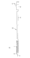
- FIG. 1 is a schematic front view showing an embodiment of the present invention.
- FIG. 2 is a schematic front view showing a use state of the embodiment.
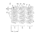
- FIG. 3 is an enlarged plan view of the stent in a reduced diameter state.
- FIG. 4 is an enlarged plan view of the expanded stent.
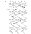
- FIG. 5 is an enlarged plan view of the bent portion.
- FIG. 6 is a schematic sectional view taken along line 6-6 of FIG.
- FIG. 7 is a schematic front view of the coating apparatus.
- FIG. 8 is a schematic sectional view taken along line 8-8 of FIG.
- FIG. 9 is a cross-sectional view of the mandrel portion.
- FIG. 10 is a flowchart of the coating method.
- FIG. 11 is a flowchart of the coating method following FIG.
- FIG. 1 a cylindrical stent body 2 having a mesh shape formed by thin struts 3, and a drug coating layer 4 coated on the surface of the stent body 2 ( (See FIG. 6).
- the stent 1 is placed inside a blood vessel or the like using, for example, a stent delivery system as shown in FIG.
- the stent delivery system 10 includes a double-pipe shaft main body 13 composed of an inner tube 11 and an outer tube 12 arranged concentrically, and a foldable and expandable balloon provided at the distal end of the shaft main body 13. 14 and a branch hub 16 having an injection port 15 for injecting a balloon expansion fluid.
- the stent 1 In order to place the stent 1 in the blood vessel using the system 10, first, the stent 1 is reduced in diameter so as to enclose the balloon 14 in a folded state and attached to the system 10, and then the distal end is released. A guide wire is inserted into the inner tube 11, and the system 10 with the stent 1 mounted thereon is guided to a predetermined position in the blood vessel using the guide wire as a guide. Then, the fluid is injected from the injection port 15 and flows into the balloon 14 through the lumen between the inner tube 11 and the outer tube 12 to expand the balloon 14. When the stent 1 attached here is expanded radially outward from the inside, the stent 1 expands in the radial direction and / or the axial direction, undergoes plastic deformation, and is placed in a state of being expanded in the blood vessel.
- the stent body 2 of the present embodiment includes a bent portion K1 having a U-shape with a small opening angle ⁇ , a bent portion K2 having a V-shape with a large opening angle ⁇ , and a straight portion.
- a wave-like annular body C (also referred to as “cell portion C”) is formed by annularly arranging linear portions S formed of curved portions. The length in the axial direction of each cell portion C is “L1”.
- the cell shown in FIG. 1 is composed of 14 cell portions C.
- the opening angle ⁇ increases as shown in FIG. 4, and the struts 3 constituting the bent portion K1 and the bent portion K2 are mutually connected. It will be spaced apart and it will be in the expansion state which the space
- the bent portions K1 and K2 of the stent body 2 are not preferably bent at an acute angle, and are preferably bent or curved in a U shape or a gentle arc shape. Thereby, generation
- the bent end bends so that it does not bulge outward, that is, the bent end does not bulge outward in an arc shape. In this way, the outer diameter at the time of diameter reduction can be reduced, and insertion into a small-diameter in vivo organ (for example, a blood vessel) is also advantageous.
- the material for forming the stent body 2 is preferably a biocompatible material, such as stainless steel, tantalum or tantalum alloy, platinum or platinum alloy, gold or gold alloy, cobalt base alloy, cobalt chromium alloy, titanium alloy, niobium. Alloys are preferred.
- a biocompatible material such as stainless steel, tantalum or tantalum alloy, platinum or platinum alloy, gold or gold alloy, cobalt base alloy, cobalt chromium alloy, titanium alloy, niobium. Alloys are preferred.
- stainless steel SUS316L having the most corrosion resistance is suitable.
- the area occupied by the struts 3 when mounted on the balloon 14 is preferably 60% to 80% of the area of the entire outer peripheral surface including the void O.
- the width of the strut 3 is preferably 40 ⁇ m to 150 ⁇ m, and particularly preferably 80 ⁇ m to 120 ⁇ m.
- the length L1 in the axial direction of each cell portion C is preferably 0.5 mm to 2.0 mm, particularly preferably 0.9 mm to 1.5 mm.
- the diameter D1 of the stent body 2 when not expanded is preferably 0.8 mm to 2.5 mm, and more preferably 0.9 mm to 2.0 mm.
- the length L2 when not expanded is preferably about 8 mm to 40 mm.
- the stent body 2 is formed by removing a portion other than the strut from the tube (specifically, a metal pipe) to form a predetermined pattern. For example, it is performed by removing the void O from the metal pipe by a masking method called photofabrication and an etching method using chemicals, an electric discharge machining method using a mold, a cutting method (for example, mechanical polishing, laser cutting), or the like. Is called.
- edges of the struts 3 are removed by chemical polishing or electrolytic polishing and finished to a smooth surface.
- Annealing improves overall stent flexibility and flexibility, improves placement in bent vessels, reduces physical irritation to the vessel inner wall, and reduces restenosis factors .
- Annealing is performed by heating to 900 ° C to 1200 ° C under an inert gas atmosphere (for example, a mixed gas of nitrogen and hydrogen) and then slowly cooling so that an oxide film is not formed on the stent surface. Is preferred.
- a dipping method for the formation of the drug coat layer 4, various methods such as a dipping method, a spray method, an ink jet method, and a nozzle injection method can be used.
- a spray method, an ink jet method, and a nozzle injection method are preferable.
- the spray method is a method in which a drug is sprayed onto the outer surface of the stent body 2 together with an air flow to form the drug coat layer 4. It is applied to the outer surface, and the nozzle injection method is to apply a medicine to the outer surface of the stent body 2 from the nozzle.
- the drug coat layer can be easily and quickly formed.
- the drug coat layer can be formed with high accuracy with little loss of the drug.
- the spray method, the ink jet method, and the nozzle injection method are basically different only in the process of applying the drug to the outer surface of the stent body 2, and the configuration of the drug coat layer 4 to be formed is the same. A case where the drug coat layer 4 is formed using the nozzle injection method will be described.
- FIG. 5 is an enlarged plan view of the bent portion
- FIG. 6 is a schematic sectional view taken along line 6-6 of FIG.
- the drug coat layer 4 as shown in FIGS. 5 and 6 is formed on the outer surface of the stent body 2 described above.
- a laminating method is used in which the coating liquid is applied directly and applied along the strut 3 many times, and the thickness B of the drug coat layer 4 is formed so as to gradually decrease toward the bent portion K.
- a primer coat layer 5 is preferably provided between the stent body 2 and the drug coat layer 4. Since the primer coat layer 5 is made of a material having an adhesive property with a polymer constituting the drug coat layer described later, the stent body 2 is well bonded to the drug and becomes a stent with less peelability. .
- the drug coat layer 4 of the present embodiment has a substantially uniform thickness B in the linear portion S composed of a straight portion or a curved portion of the stent body 2.
- the thickness B that reaches the bent portion K gradually decreases, and the gradually decreasing portion 6 is formed so as to be an uncoated layer or a very thin drug-coated layer at which the drug is not coated at or near the bending point P.
- the nozzle described later is moved along a predetermined pattern of the stent body 2, and the medicine is discharged onto the surface of the stent body 2 to form a plurality of thin coating layers 4a having a thin thickness b.
- the coating area of each thin film coat layer 4a is adjusted as the nozzle approaches the bending point P and its vicinity, and the number of thin film coat layers 4a can be reduced stepwise.
- the thickness B of the drug coat layer can be gradually decreased, and the valley-shaped gradually decreasing portion 6 centering on the bending point P and the vicinity thereof can be formed. The formation of the thin film coat layer 4a will be described in detail later.
- the thickness B of the drug coat layer 4 is gradually reduced toward the bent portion K and the vicinity thereof, when the stent 1 is expanded in the radial direction, the starting point at which the stent body 2 is deformed is the bent point of the bent portion K. Even if there is a slight deviation from P, since the deformation starting point and the thickness of the drug coat layer 4 existing in the vicinity thereof are thin, the occurrence of strain and stress concentration in the drug coat layer 4 are greatly reduced.
- the position of the bending point P in the stent body 2 is geometrically a so-called inflection point at the bending portion K, but an expansion force is actually applied from the inside of the stent using a balloon or the like, and the stent 1
- the starting point of deformation of the bent portion K of the stent body 2 is not always an inflection point, but changes depending on the direction of action of the expansion force applied to the strut 3 and cannot be uniquely identified.
- the gradually decreasing portion 6 of the drug coat layer 4 is formed and the thickness B of the drug coat layer 4 is gradually decreased toward the bent portion K and the vicinity thereof, the position of the bending point P in the stent body 2 slightly changes.
- the drug coat layer 4 is deformed following the stent body 2, and the strain and stress concentration generated in the drug coat layer 4 are extremely small.
- this portion has a small amount of drug applied, the drug itself can easily follow the deformation of the stent body 2. As a result, in combination, the effect of preventing the drug from dropping off is greatly improved.
- the thickness b of one thin film coat layer 4a is 1 ⁇ m to 5 ⁇ m, and the number of thin film coat layers 4a is 1 to 50 layers, the length X of the bent portion K is 50 ⁇ m to 1000 ⁇ m, the length Y between the end portions of the upper and lower thin film coat layers 4a (however, the length between the end portions may not be uniform) is 1 ⁇ m to 1,000 ⁇ m is preferred.
- the inclination angle ⁇ of the gradually decreasing portion 6 is less than 90 degrees, preferably 1 to 60 degrees, and more preferably 1 to 45 degrees.
- the inclination angle ⁇ is less than 1 degree, the effect of suppressing the dropout of the drug is exerted over a wide range, but the amount of the drug to be coated may be reduced, which is not preferable. Since the suppression effect may be reduced, it is not preferable. And those having an inclination angle ⁇ of 1 to 45 degrees are easy to manufacture by the laminating method described later.
- the range of 50 ⁇ m to 1000 ⁇ m with the bending point P as the center is a non-coated layer in which the drug coat layer 4 is not formed. Since the drug is not coated on the part where the drug is likely to occur, it becomes a stent with a high ability to suppress drug dropout, and it can be easily dealt with even when a situation where the stent needs to be expanded greatly occurs, for example, The stent is easy to handle, the procedure is easy and reliable, and the stent is extremely easy to use.
- the present invention is not necessarily limited to only the uncoated layer, and the bent portion K may have one to several thin film coated layers 4a.
- the drug coat layer 4 is composed of a mixture of a drug and a polymer. This mixture is more preferably constituted by a mixture of a drug and a biodegradable polymer. After the stent is placed in the living body, when the polymer covering and protecting the drug is biodegraded, the drug is gradually released, and restenosis in the stent placement part is surely prevented.
- the biodegradable polymer it is preferable to use any of polylactic acid, polyglycolic acid, and a copolymer of lactic acid and glycolic acid.
- the mixing ratio of the drug and the polymer in each thin film coat layer 4a of the drug coat layer 4 may be the same or different.
- the ratio of the drug to the polymer may gradually increase from the lowermost layer to the upper layer of the thin film coat layer 4a in contact with the primer coat layer 5.
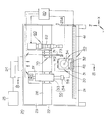
- FIG. 7 is a schematic front view of the coating apparatus
- FIG. 8 is a schematic cross-sectional view taken along line 8-8 in FIG. 7
- FIG. 9 is a cross-sectional view of the mandrel portion.
- an airtight chamber 23 is formed inside by covering a frame 22 standing on the base 21 with a transparent synthetic resin plate (not shown) from the outer surface.
- a duct 24 is connected to the top of the chamber 23, and air whose temperature and humidity are controlled is supplied from an air conditioner 25, the inside of the chamber is kept in a constant temperature and humidity state, and a coating material W described later is applied to the stent body 2.
- the drying and solidification conditions are always kept constant.
- a holding tool 30 for holding the stent body 2 and a moving means 40 for moving the holding tool 30 are provided at the lower part in the chamber 23, and an intermediate part in the chamber 23 is horizontally mounted on the frame 22.
- An application head 50 for applying the coating material W onto the strut 3 of the stent body 2 to the support frame 26, and the position information in the XY directions in the orthogonal coordinate system on the surface of the stent body 2, that is, the surface of the strut 3 is acquired.
- the first position information acquisition unit 60 that acquires the position information in the Z direction in the orthogonal coordinate system is attached.
- a control unit 80 is provided outside the chamber 23 to control the holder 30, the moving unit 40, the coating head 50, and both position information acquisition units 60 and 70.
- the holder 30 is provided such that the proximal end of the mandrel 34 is chucked to a chuck portion 33 connected to a motor M ⁇ b> 2 that can rotate forward and backward, and the stent body 2 is detachably provided on the outer periphery of the mandrel 34. It has been.
- the motor M2 is mounted on the slide part 32, and the slide part 32 is movably provided on the substrate 31 (Y direction).
- the substrate 31 moves along a traveling rail 41 which is a so-called linear motor type drive source. It is mounted on the moving table 42 (X direction). Thereby, the holder 30 can move the stent body 2 in the forward / reverse rotation, the X direction, and the Y direction.
- the outer diameter of the mandrel 34 is preferably substantially the same as or slightly larger than the inner diameter of the stent body 2, but the mandrel 34 can be exchanged according to the inner diameter of the stent body 2, and several types of outer diameters are prepared. Yes. In either case, the contrast ratio between the strut 3 and the space O of the mounted stent body 2 is increased by coating with a black paint so as to absorb light. Further, as shown in FIG. 9, the mandrel 34 has a recess 35 formed on the outer peripheral surface, and when the stent body 2 is mounted on the mandrel 34, the outer surface of the mandrel 34 and the lower surface 3 a of the strut 3 of the stent body 2 are formed.
- the coating material W When the coating material W is applied onto the strut 3 by creating a gap G therebetween, the coating material W is prevented from wrapping around between the surface of the mandrel 34 and the inner surface of the stent body 2, and a uniform coating layer is formed. Convenient for forming and working.
- the application head 50 is a vertical table (not shown) that is moved in the Z direction by a bracket 51 attached to the support frame 26, for example, by a screw feed mechanism driven by a motor M3. And a dispenser 53 that gradually discharges the coating material W stored therein and a nozzle portion 54 that discharges the coating material W.
- the dispenser 53 is a syringe operation mechanism, and includes a cylinder part 55 in which the coating material W is stored, a piston part 56 slidably provided in the cylinder part 55, and a piston part. And a drive unit (not shown) such as a motor or a hydraulic mechanism that presses 56 with a predetermined force F.
- the nozzle portion 54 includes an attachment member 57 provided at the lower end of the cylinder portion 55 and a nozzle 58 that hangs down from the attachment member 57.
- a flow path (non-flow path) through which the coating material W flows from the cylinder portion 55 to the nozzle 58. (Shown) is formed.
- the outer diameter of the tip of the nozzle 58 is 10 ⁇ m to 1000 ⁇ m, and the inner diameter of the tip is 1 ⁇ m to 500 ⁇ m, preferably 5 ⁇ m to 250 ⁇ m so that the coating material W having the viscosity described later is extruded at a predetermined discharge speed.
- the thickness is less than 5 ⁇ m, the coating material W does not flow out smoothly, and a large pressure may be required for ejection.
- the nozzle 58 is preferably polished so as to make the unevenness of the surface as small as possible in order to prevent adhesion of the discharged coating material W.
- stainless steel, carbon steel, nickel, titanium It is preferable to use chromium, glass, aluminum oxide, zirconium oxide, diamond, or a composite of these.
- the dispenser 53 is separated from the strut 3 so that the distance N between the nozzle 58 and the strut 3 becomes a predetermined length, and the coating material W is continuously pushed out from the nozzle 58 toward the surface of the strut 3 without interruption.
- 3 is provided so as to be placed on the surface of 3.
- the viscosity of the coating material W discharged from the nozzle 58 is 0.1 cp to 10 cp, preferably 1.0 cp to 4.0 cp. If the viscosity is higher than the above range, a large pressure may be required for discharge or the thin nozzle 58 may not be able to discharge. If the viscosity is lower than the above range, the discharged coating material W leaks from the strut 3 and forms a uniform coating layer. Sometimes it cannot be formed.
- the distance N between the nozzle 58 and the strut 3 is 0.1 ⁇ m to 200 ⁇ m, preferably 1 ⁇ m to 100 ⁇ m. If the distance N is wider than the above range, there is a problem that the coating material W is interrupted, and if the distance N is narrower than the above range, there is a problem that the coating material W leaks from the strut surface.
- the first position information acquisition means 60 is an imaging means that is fixedly attached to the support frame 26 via a bracket (not shown).
- the first position information acquisition means 60 includes a camera unit 62 and a shaft of the stent body 2.
- a line sensor portion (not shown) arranged to extend in the direction, and scans the surface of the stent body 2 in synchronization with the rotation of the stent body 2 of the holder 30, and an image of the surface of the stent body 2 Is transmitted to the control unit 80.
- the mandrel 34 is painted with a black paint so as to increase the contrast ratio between the strut 3 of the mounted stent body 2 and the space O and absorbs light.
- the control unit 80 binarizes the surface image of the obtained stent body 2 with appropriate luminance, thereby separating it into the strut 3 and the space O, and the coordinates of the strut 3, that is, the X ⁇ of the strut 3.
- the position information in the Y direction can be used.
- the control unit 80 calculates the coordinates of the trajectory passing through the center of the straddle 3 based on the obtained position information in the XY direction (XY coordinates of the strut 3), and the obtained data of the central trajectory is And stored in the memory of the control unit 80.
- the second position information acquisition means 70 is a Z-direction displacement measurement means that is fixedly attached to the lower end of a bracket 71 attached to the support frame 26, and is referred to as a so-called vertical sensor.
- the laser displacement sensor 73 measures the displacement of the strut 3 in the Z direction.
- the strut 3 does not have a smooth surface but has irregularities, and in order to apply the coating material W quantitatively and accurately to such irregularities, the tip of the nozzle 58 is It must move so as to be strictly parallel to the surface of the strut 3 and apply a predetermined amount of the coating material W. Therefore, acquisition is started from the position information of the strut 3 at a predetermined position of the stent body 2, for example, the application start point by the laser displacement sensor 73, and along the trajectory passing through the center of the strut 3 while rotating the stent body 2 forward and backward. The displacement data in the Z direction of the entire stent body 2 is collected, and the obtained displacement data is stored in the memory of the control unit 80.
- control unit 80 includes a processor, a monitor, a keyboard, and the like. From the various pieces of position information, the control unit 80 sets the application mode for applying the coating material W, and the application head 50 uses the struts of the stent body 2. 3, an application path for applying the coating material W is determined. Further, the rotation of the mandrel 34 in the holder 30, the movement of the moving means 40, the discharge amount of the coating material W discharged from the coating head 50, the scanning of the imaging means and the vertical sensor, and the like are controlled.
- Application mode refers to the application route when applying along the strut 3.
- the application route is preferably a route in which the entire strut 3 can be continuously applied without any overlapping application section, but in the case of the stent 1 in which the struts 3 intersect in a complicated manner, it is difficult to set a route without an overlapping application section. There is also. In such a case, a section for overlapping application is provided, or a section for jumping from one point on the strut 3 to another point is provided. In this way, the application route can be shortened by providing a section that partially overlaps or a section that jumps.
- the drug in overlapping sections (sections that pass a plurality of times), can be uniformly applied to a desired portion of the stent body 2 by setting the speed faster than the moving speed of a section that passes a single time, and restenosis in the case of PTCA, etc.
- the effect of reducing the rate can be sufficiently exhibited.
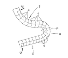
- the coating material W is applied to the strut 3 of the stent body 2, it is preferable that, in the linear portion S of the strut 3, the trajectory passing through the center of the strut 3 is the application path. However, in the bent portion K of the strut 3, it is preferable that a trajectory passing through a position shifted by a predetermined amount in the width direction of the strut 3 is the application path.
- the coating material W is a liquid and is present on the surface of the strut 3 in a raised state due to the surface tension. Even if this is dried and solidified, the coating material W tends to become a coating layer having a circular cross section.
- the coating when the coating is applied a plurality of times, it tends to swell up in an arc shape, so that the second coating layer is formed with the trajectory passing through a position shifted by a predetermined amount from the first coating layer of the strut 3 as the coating path.
- the application path is a trajectory passing through a position different from the first and second application paths.
- the application path is made different between the linear portion S and the bent portion K.
- the trajectory passing through the center in the width direction of the strut 3 may be used as the application path.
- the coating material W discharged from the coating head 50 is influenced by its viscosity, the falling speed from the nozzle, and the like, and does not follow along the movement track of the coating head 50. Therefore, it is preferable to set the outside of the line passing through the center of the bent portion K of the strut 3 as the application path.
- the intersection of the central axes of the plurality of struts 3 or the vicinity of the intersection is used as the coating path. Since the coating path P also intersects at the portion where the struts 3 intersect, it is preferable that the intersection of the central axes of the struts 3 or the vicinity of the intersection be the coating path because the coating material W can be prevented from flowing down.
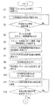
- FIG. 10 is a flowchart of the coating method
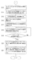
- FIG. 11 is a flowchart of the coating method following FIG.
- ⁇ Preparation process> when starting the coating, the air conditioner 25 is operated to bring the chamber 23 into a constant temperature and humidity state.
- a syringe operating mechanism 53 formed by combining a nozzle portion 54 having a nozzle 58 having an inner diameter corresponding to the width of the strut 3 and the coating material W and a cylinder portion 55 into which the coating material W is injected is set on the support frame 26. To do.
- the stent body 2 is mounted on the mandrel 34, the stent body 2 is attached to the chuck portion 33 of the holder 30 in the standby position, and set so that the application start point of the strut 3 is positioned on the concave portion 35 of the mandrel 34.
- the standby position is in the vicinity of the inlet 23 ⁇ / b> A of the chamber 23 when the moving means 40 is provided in the lower portion of the chamber 23.
- the control unit 80 receives input of imaging parameters and stores the input imaging parameters in the storage device (S1).
- the imaging parameters are input by an operator, for example, from a keyboard.
- the imaging parameters include the rotation speed of the mandrel 34, the number of shooting lines, the shooting line width, and the shooting operating speed.
- the control unit 80 commands the start of imaging after storing the input imaging parameters.
- the X-direction moving means 40x is activated (S2).
- the holder 30 moves from the standby position below the first position information acquisition means 60 along the traveling rail 41.
- the control unit 80 confirms that the holder 30 has reached the predetermined position (S3), and when the holder 30 reaches the predetermined position, operates the motor M2 of the holder 30 to start the rotation of the stent 1. (S4).
- the line sensor of the first position information acquisition means 60 starts imaging in response to an imaging start command, scans the surface of the stent body 2, and images the surface pattern (S5).
- the captured image is stored in a storage device (for example, a memory or a hard disk) in the control unit 80 as a flat developed image.
- the image may be output to a monitor so that it can be visually confirmed.
- the control unit 80 converts it into a black and white binary image with a certain brightness as a boundary (S6).
- the coordinates of the trajectory passing through the center of the strut 3 are calculated by the thinning process of the width (S7).
- ⁇ Application mode setting process> Judging from the acquired surface image of the stent body 2 and considering the necessity and position of the overlapping application section and the jumping section, the desired surface portion of the strut 3 is applied, and the overlapping application section and the jumping section are as much as possible.
- the application route is set so as to be less or shorter (S8).
- the control unit 80 receives and stores the input of the displacement measurement parameter of the second position information acquisition unit 70 which is a displacement measurement unit in the Z direction (S9).
- This displacement measurement parameter is also input by the operator.
- the displacement measurement parameters include a measurement start position, a measurement direction, a direction at a branch point, a measurement speed, and a measurement interval.
- the control unit 80 operates the motor M1 of the Y-direction moving unit 40y after storing the displacement measurement parameters (S10). If necessary, the measurement positions of the stent body 2 and the displacement measuring means are adjusted while observing with a video camera and a monitor so that the measurement position of the displacement measuring means coincides with the designated position on the trajectory (S11).
- the control unit 80 sends the second position information acquisition unit 70 to the Z direction in the strut 3
- the start of displacement measurement is commanded (S13).
- the control unit 80 repeats forward / reverse rotation by the motor M2 and axial movement by the motor M1.
- the stent body 2 repeats rotation and axial movement (S14).
- the second position information acquisition means 70 moves along a trajectory passing through the center of the strut 3, so that the control unit 80 collects displacement data in the Z direction (S15).
- This displacement data is stored in the storage device of the control unit 80 together with the coordinates of the central trajectory.
- the control unit 80 receives the input application parameter and stores it (S16).
- Application parameters are also input from the operator.
- Application parameters include application start position, application direction, intersection direction, trajectory adjustment section setting, trajectory adjustment amount, application speed, coating material W ejection speed, application head height, number of applications (number of layers). Includes selection of application heads.
- Control unit 80 commands application start after storing application parameters.
- the movement of the holder 30 is commanded by the X direction moving means 40x (S17).
- the stent body 2 is moved to the application start position under the application head 50 (S18).
- the stent main body 2 reaches the application start position under the application head 50 (S19: Yes)
- the stent main body 2 is moved by the motor M2.
- the forward / reverse rotation and the movement in the axial direction by the motor M1 are moved in the x-axis direction and the y-axis direction according to the designated parameters (S20).
- the coating head 50 is moved in the Z-axis direction by the motor M3 according to the designated parameter (S21). At this time, the coating material W is continuously discharged from the coating head 50. As a result, the coating material W is applied while the application head 50 moves along a predetermined application path.
- the coating material W is discharged in a constant amount, and the amount of the drug on the stent body 2 also reaches a predetermined value. Set reliably. In addition, there is no web or bridge between the struts 3, and the drug coat layer 4 can be formed with extremely high accuracy.
- the holder 30 When the coating is completed, the holder 30 is moved to the standby position by the X-direction moving means 40x, the mandrel 34 is removed from the holder 30 and taken out of the chamber 23, and the stent body 2 on which the drug coat layer 4 is formed is removed from the mandrel. Remove from 34.
- the present invention is not limited to the embodiment described above, and various modifications can be made by those skilled in the art within the technical idea of the present invention.
- the gradual decrease portion 6 in which the thickness B of the drug coat layer changes linearly toward the bent portion K or the vicinity thereof is mentioned, but the shape of the gradual decrease portion 6 of the present invention is Not only this, it is sufficient that the thickness B of the drug coat layer is thin in the bent portion K and the vicinity thereof, and various shapes such as an arc shape may be used.
- the coating material W is not limited to one type, and may be a plurality.
- a plurality of syringes, nozzles and syringe operating mechanisms are prepared and sequentially switched for coating.
- the sequential switching of these syringe operation mechanisms and the like is controlled by the control unit 80.
- the different coating materials W refer to cases where the polymers are different or the polymers are the same and the amounts thereof are different, or the agents are different or the agents are the same and the amounts are different, or the solvents are different. If a plurality of types of coating materials are used in this way, the medicinal effects become complex, and it is extremely advantageous for the patient to reduce physical and mental pain.
- the method of forming the drug coat layer 4 is not limited to the above-described embodiment, and for example, spray or ink jet may be used.
- the above-described embodiment is a stent having a predetermined pattern having a wave shape, but is not limited to such a stent, and has other patterns as long as it has a bent portion K. It may be a thing.
- the present invention can be used as a stent that significantly reduces the restenosis rate after percutaneous coronary angioplasty (PTCA).
- PTCA percutaneous coronary angioplasty
Landscapes
- Health & Medical Sciences (AREA)
- Engineering & Computer Science (AREA)
- Biomedical Technology (AREA)
- Life Sciences & Earth Sciences (AREA)
- Heart & Thoracic Surgery (AREA)
- Vascular Medicine (AREA)
- Animal Behavior & Ethology (AREA)
- General Health & Medical Sciences (AREA)
- Public Health (AREA)
- Veterinary Medicine (AREA)
- Cardiology (AREA)
- Oral & Maxillofacial Surgery (AREA)
- Transplantation (AREA)
- Surgery (AREA)
- Epidemiology (AREA)
- Physics & Mathematics (AREA)
- Optics & Photonics (AREA)
- Chemical & Material Sciences (AREA)
- Medicinal Chemistry (AREA)
- Molecular Biology (AREA)
- Gastroenterology & Hepatology (AREA)
- Pulmonology (AREA)
- Media Introduction/Drainage Providing Device (AREA)
- Chemical Kinetics & Catalysis (AREA)
- Polymers & Plastics (AREA)
- Organic Chemistry (AREA)
- Materials For Medical Uses (AREA)
Abstract
Priority Applications (12)
| Application Number | Priority Date | Filing Date | Title |
|---|---|---|---|
| ES10820337.3T ES2638548T3 (es) | 2009-09-30 | 2010-09-13 | Stent |
| SG2011097466A SG177443A1 (en) | 2009-09-30 | 2010-09-13 | Stent |
| JP2011534175A JP5570515B2 (ja) | 2009-09-30 | 2010-09-13 | ステント |
| AU2010301898A AU2010301898B2 (en) | 2009-09-30 | 2010-09-13 | Stent |
| EP10820337.3A EP2444034B1 (fr) | 2009-09-30 | 2010-09-13 | Stent |
| CA2767994A CA2767994C (fr) | 2009-09-30 | 2010-09-13 | Stent |
| CN201080023374.5A CN102448406B (zh) | 2009-09-30 | 2010-09-13 | 支架 |
| BR112012007578-0A BR112012007578B1 (pt) | 2009-09-30 | 2010-09-13 | stent |
| KR1020127004325A KR101687436B1 (ko) | 2009-09-30 | 2010-09-13 | 스텐트 |
| US13/413,372 US9095459B2 (en) | 2009-09-30 | 2012-03-06 | Stent with drug coat layer including a gradual stepwise decrease portion |
| US14/733,707 US9737423B2 (en) | 2009-09-30 | 2015-06-08 | Stent with drug coat layer |
| AU2015261573A AU2015261573B2 (en) | 2009-09-30 | 2015-11-24 | Stent |
Applications Claiming Priority (2)
| Application Number | Priority Date | Filing Date | Title |
|---|---|---|---|
| JP2009227417 | 2009-09-30 | ||
| JP2009-227417 | 2009-09-30 |
Related Child Applications (1)
| Application Number | Title | Priority Date | Filing Date |
|---|---|---|---|
| US13/413,372 Continuation-In-Part US9095459B2 (en) | 2009-09-30 | 2012-03-06 | Stent with drug coat layer including a gradual stepwise decrease portion |
Publications (1)
| Publication Number | Publication Date |
|---|---|
| WO2011040218A1 true WO2011040218A1 (fr) | 2011-04-07 |
Family
ID=43826044
Family Applications (1)
| Application Number | Title | Priority Date | Filing Date |
|---|---|---|---|
| PCT/JP2010/065740 WO2011040218A1 (fr) | 2009-09-30 | 2010-09-13 | Stent |
Country Status (11)
| Country | Link |
|---|---|
| US (2) | US9095459B2 (fr) |
| EP (1) | EP2444034B1 (fr) |
| JP (1) | JP5570515B2 (fr) |
| KR (1) | KR101687436B1 (fr) |
| CN (1) | CN102448406B (fr) |
| AU (1) | AU2010301898B2 (fr) |
| BR (1) | BR112012007578B1 (fr) |
| CA (1) | CA2767994C (fr) |
| ES (1) | ES2638548T3 (fr) |
| SG (1) | SG177443A1 (fr) |
| WO (1) | WO2011040218A1 (fr) |
Cited By (11)
| Publication number | Priority date | Publication date | Assignee | Title |
|---|---|---|---|---|
| WO2013172938A1 (fr) * | 2012-05-14 | 2013-11-21 | C.R. Bard, Inc. | Endoprothèse uniformément extensible |
| WO2014162400A1 (fr) * | 2013-04-01 | 2014-10-09 | テルモ株式会社 | Système de largage d'endoprothèse |
| USD723165S1 (en) | 2013-03-12 | 2015-02-24 | C. R. Bard, Inc. | Stent |
| WO2015046168A1 (fr) * | 2013-09-27 | 2015-04-02 | テルモ株式会社 | Procédé de production d'endoprothèse, et dispositif de revêtement |
| WO2015046022A1 (fr) * | 2013-09-27 | 2015-04-02 | テルモ株式会社 | Stent, et procédé de production de stent |
| CN104717941A (zh) * | 2013-01-30 | 2015-06-17 | 泰尔茂株式会社 | 生物体管腔用治疗系统及支架 |
| WO2016103941A1 (fr) * | 2014-12-24 | 2016-06-30 | テルモ株式会社 | Procédé de production de stent |
| WO2020045268A1 (fr) * | 2018-08-29 | 2020-03-05 | 株式会社ノーリツ | Enveloppe externe pour unité d'eau chaude, et unité d'eau chaude dotée de ladite enveloppe |
| JP2020034216A (ja) * | 2018-08-29 | 2020-03-05 | 株式会社ノーリツ | 温水ユニット用の外装ケースの製造方法 |
| WO2022176792A1 (fr) * | 2021-02-19 | 2022-08-25 | テルモ株式会社 | Endoprothèse et son procédé de fabrication |
| JP7506619B2 (ja) | 2021-02-19 | 2024-06-26 | テルモ株式会社 | ステントの製造方法およびステント |
Families Citing this family (14)
| Publication number | Priority date | Publication date | Assignee | Title |
|---|---|---|---|---|
| US20090093875A1 (en) * | 2007-05-01 | 2009-04-09 | Abbott Laboratories | Drug eluting stents with prolonged local elution profiles with high local concentrations and low systemic concentrations |
| JP5530361B2 (ja) * | 2008-09-17 | 2014-06-25 | テルモ株式会社 | ステント |
| WO2015023077A1 (fr) * | 2013-08-13 | 2015-02-19 | 주식회사 티앤알바이오팹 | Appareil et procédé de fabrication d'une endoprothèse biodégradable |
| CN103705324B (zh) * | 2013-12-31 | 2016-06-29 | 深圳市先健生物材料技术有限公司 | 血管涂层支架的制备方法 |
| EP3750477A1 (fr) | 2015-05-07 | 2020-12-16 | Ecom Medical, Inc. | Procédés de fabrication d'une sonde invasive d'ecg |
| CN108778195A (zh) * | 2016-03-16 | 2018-11-09 | 泰尔茂株式会社 | 支架 |
| CN107090661A (zh) * | 2017-05-22 | 2017-08-25 | 海安国洋机械科技有限公司 | 自喷式金属纤维牵切铺毡机 |
| KR101976074B1 (ko) * | 2017-07-10 | 2019-05-08 | 주식회사 엠아이텍 | 생분해성 스텐트 제조 방법 |
| KR102416460B1 (ko) * | 2017-08-14 | 2022-07-05 | 보스톤 싸이엔티픽 싸이메드 인코포레이티드 | 의료용 스텐트 |
| US11465171B2 (en) * | 2017-08-21 | 2022-10-11 | Ecom Medical, Inc. | Systems and methods for applying materials to medical devices |
| CN113597291A (zh) * | 2018-11-26 | 2021-11-02 | 内弗罗尼公司 | 体腔中的流动调节装置 |
| US11998464B2 (en) | 2020-07-24 | 2024-06-04 | Medtronic Vascular, Inc. | Stent with angled struts and crowns |
| US11986408B2 (en) | 2020-07-24 | 2024-05-21 | Medtronic Vascular, Inc. | Stent with mid-crowns |
| CN112826644A (zh) * | 2020-12-31 | 2021-05-25 | 中国人民解放军总医院第一医学中心 | 一种防血栓血管内支架 |
Citations (5)
| Publication number | Priority date | Publication date | Assignee | Title |
|---|---|---|---|---|
| JPH09285548A (ja) * | 1996-04-10 | 1997-11-04 | Advanced Cardeovascular Syst Inc | 長さ方向に沿って変化する構造的強度をもつステント |
| EP1277449A1 (fr) * | 2001-07-20 | 2003-01-22 | SORIN BIOMEDICA CARDIO S.p.A. | Stent |
| WO2003009779A2 (fr) | 2001-07-26 | 2003-02-06 | Avantec Vascular Corporation | Administration d'agents potentiellement therapeutiques |
| JP2004528928A (ja) * | 2001-06-04 | 2004-09-24 | サイメッド ライフ システムズ,インコーポレーテッド | コーティング保持能力を高めた血管ステント |
| WO2008024712A2 (fr) * | 2006-08-22 | 2008-02-28 | Abbott Cardiovascular Systems Inc. | Stent intravasculaire |
Family Cites Families (26)
| Publication number | Priority date | Publication date | Assignee | Title |
|---|---|---|---|---|
| US5282823A (en) * | 1992-03-19 | 1994-02-01 | Medtronic, Inc. | Intravascular radially expandable stent |
| AU716005B2 (en) * | 1995-06-07 | 2000-02-17 | Cook Medical Technologies Llc | Implantable medical device |
| US20040243097A1 (en) * | 2000-05-12 | 2004-12-02 | Robert Falotico | Antiproliferative drug and delivery device |
| US6395326B1 (en) * | 2000-05-31 | 2002-05-28 | Advanced Cardiovascular Systems, Inc. | Apparatus and method for depositing a coating onto a surface of a prosthesis |
| US6805898B1 (en) * | 2000-09-28 | 2004-10-19 | Advanced Cardiovascular Systems, Inc. | Surface features of an implantable medical device |
| US6979346B1 (en) * | 2001-08-08 | 2005-12-27 | Advanced Cardiovascular Systems, Inc. | System and method for improved stent retention |
| US20030088307A1 (en) * | 2001-11-05 | 2003-05-08 | Shulze John E. | Potent coatings for stents |
| CN101467921B (zh) * | 2001-11-05 | 2012-08-15 | 生物传感器国际集团有限公司 | 药物洗脱支架的生产方法 |
| US6939376B2 (en) * | 2001-11-05 | 2005-09-06 | Sun Biomedical, Ltd. | Drug-delivery endovascular stent and method for treating restenosis |
| US7014654B2 (en) * | 2001-11-30 | 2006-03-21 | Scimed Life Systems, Inc. | Stent designed for the delivery of therapeutic substance or other agents |
| WO2003061625A2 (fr) * | 2002-01-18 | 2003-07-31 | Snyder Michael E | Dispositif ophtalmologique a liberation prolongee et son procede de fabrication et d'utilisation |
| DE60333566D1 (de) * | 2002-08-13 | 2010-09-09 | Medtronic Inc | Medizinische vorrichtung mit verbesserter haftung zwischen einem polymeren berzug und einem substrat |
| US7951392B2 (en) * | 2002-08-16 | 2011-05-31 | Boston Scientific Scimed, Inc. | Microarray drug delivery coatings |
| US8281737B2 (en) * | 2003-03-10 | 2012-10-09 | Boston Scientific Scimed, Inc. | Coated medical device and method for manufacturing the same |
| US7318945B2 (en) * | 2003-07-09 | 2008-01-15 | Medtronic Vascular, Inc. | Laminated drug-polymer coated stent having dipped layers |
| US7744645B2 (en) * | 2003-09-29 | 2010-06-29 | Medtronic Vascular, Inc. | Laminated drug-polymer coated stent with dipped and cured layers |
| US8864820B2 (en) * | 2004-08-31 | 2014-10-21 | Advanced Cardiovascular Systems, Inc. | Selective coating of an implantable medical device |
| US7628807B2 (en) * | 2004-11-04 | 2009-12-08 | Boston Scientific Scimed, Inc. | Stent for delivering a therapeutic agent having increased body tissue contact surface |
| KR100511618B1 (ko) * | 2005-01-17 | 2005-08-31 | 이경범 | 약물방출 조절형 다층 코팅 스텐트 및 이의 제조방법 |
| US20070073385A1 (en) * | 2005-09-20 | 2007-03-29 | Cook Incorporated | Eluting, implantable medical device |
| DE102006038235A1 (de) * | 2006-08-07 | 2008-02-14 | Biotronik Vi Patent Ag | Verbesserung der Stabilität biodegradierbarer metallischer Stents, Verfahren und Verwendung |
| CN1923154A (zh) * | 2006-09-13 | 2007-03-07 | 东南大学 | 植入后组织脱垂小的血管支架 |
| CN201006050Y (zh) * | 2006-10-18 | 2008-01-16 | 北京乐普医疗器械有限公司 | 可生物降解高分子载药涂层心血管支架 |
| KR20140121892A (ko) * | 2007-03-20 | 2014-10-16 | 테루모 가부시키가이샤 | 코팅 방법과 코팅 장치 |
| EP2271380B1 (fr) * | 2008-04-22 | 2013-03-20 | Boston Scientific Scimed, Inc. | Dispositifs médicaux revêtus d une substance inorganique |
| JP5530361B2 (ja) * | 2008-09-17 | 2014-06-25 | テルモ株式会社 | ステント |
-
2010
- 2010-09-13 CN CN201080023374.5A patent/CN102448406B/zh active Active
- 2010-09-13 BR BR112012007578-0A patent/BR112012007578B1/pt active IP Right Grant
- 2010-09-13 CA CA2767994A patent/CA2767994C/fr active Active
- 2010-09-13 EP EP10820337.3A patent/EP2444034B1/fr active Active
- 2010-09-13 WO PCT/JP2010/065740 patent/WO2011040218A1/fr active Application Filing
- 2010-09-13 SG SG2011097466A patent/SG177443A1/en unknown
- 2010-09-13 AU AU2010301898A patent/AU2010301898B2/en active Active
- 2010-09-13 ES ES10820337.3T patent/ES2638548T3/es active Active
- 2010-09-13 KR KR1020127004325A patent/KR101687436B1/ko active IP Right Grant
- 2010-09-13 JP JP2011534175A patent/JP5570515B2/ja active Active
-
2012
- 2012-03-06 US US13/413,372 patent/US9095459B2/en active Active
-
2015
- 2015-06-08 US US14/733,707 patent/US9737423B2/en active Active
Patent Citations (6)
| Publication number | Priority date | Publication date | Assignee | Title |
|---|---|---|---|---|
| JPH09285548A (ja) * | 1996-04-10 | 1997-11-04 | Advanced Cardeovascular Syst Inc | 長さ方向に沿って変化する構造的強度をもつステント |
| JP2004528928A (ja) * | 2001-06-04 | 2004-09-24 | サイメッド ライフ システムズ,インコーポレーテッド | コーティング保持能力を高めた血管ステント |
| EP1277449A1 (fr) * | 2001-07-20 | 2003-01-22 | SORIN BIOMEDICA CARDIO S.p.A. | Stent |
| WO2003009779A2 (fr) | 2001-07-26 | 2003-02-06 | Avantec Vascular Corporation | Administration d'agents potentiellement therapeutiques |
| JP2005508671A (ja) * | 2001-07-26 | 2005-04-07 | アバンテク バスキュラー コーポレーション | 治療に有効な薬剤の送達 |
| WO2008024712A2 (fr) * | 2006-08-22 | 2008-02-28 | Abbott Cardiovascular Systems Inc. | Stent intravasculaire |
Non-Patent Citations (1)
| Title |
|---|
| See also references of EP2444034A4 |
Cited By (27)
| Publication number | Priority date | Publication date | Assignee | Title |
|---|---|---|---|---|
| US10588765B2 (en) | 2012-05-14 | 2020-03-17 | C. R. Bard, Inc. | Uniformly expandable stent |
| CN106667630A (zh) * | 2012-05-14 | 2017-05-17 | C·R·巴德公司 | 可均匀膨胀的支架 |
| WO2013172938A1 (fr) * | 2012-05-14 | 2013-11-21 | C.R. Bard, Inc. | Endoprothèse uniformément extensible |
| US9066825B2 (en) | 2012-05-14 | 2015-06-30 | C.R. Bard, Inc. | Uniformly expandable stent |
| CN104717941A (zh) * | 2013-01-30 | 2015-06-17 | 泰尔茂株式会社 | 生物体管腔用治疗系统及支架 |
| USD723165S1 (en) | 2013-03-12 | 2015-02-24 | C. R. Bard, Inc. | Stent |
| JPWO2014162400A1 (ja) * | 2013-04-01 | 2017-02-16 | テルモ株式会社 | ステントデリバリーシステム |
| WO2014162400A1 (fr) * | 2013-04-01 | 2014-10-09 | テルモ株式会社 | Système de largage d'endoprothèse |
| WO2015046022A1 (fr) * | 2013-09-27 | 2015-04-02 | テルモ株式会社 | Stent, et procédé de production de stent |
| JPWO2015046168A1 (ja) * | 2013-09-27 | 2017-03-09 | テルモ株式会社 | ステントの製造方法、および塗布装置 |
| JPWO2015046022A1 (ja) * | 2013-09-27 | 2017-03-09 | テルモ株式会社 | ステントおよびステントの製造方法 |
| EP3034048A4 (fr) * | 2013-09-27 | 2017-04-12 | Terumo Kabushiki Kaisha | Procédé de production d'endoprothèse, et dispositif de revêtement |
| WO2015046168A1 (fr) * | 2013-09-27 | 2015-04-02 | テルモ株式会社 | Procédé de production d'endoprothèse, et dispositif de revêtement |
| EP3034049A4 (fr) * | 2013-09-27 | 2017-04-19 | Terumo Kabushiki Kaisha | Stent, et procédé de production de stent |
| US10709590B2 (en) | 2013-09-27 | 2020-07-14 | Terumo Kabushiki Kaisha | Manufacturing method of stent and coating device |
| WO2016103941A1 (fr) * | 2014-12-24 | 2016-06-30 | テルモ株式会社 | Procédé de production de stent |
| WO2020045267A1 (fr) * | 2018-08-29 | 2020-03-05 | 株式会社ノーリツ | Procédé de fabrication d'enveloppe externe pour unité d'eau chaude |
| JP2020034217A (ja) * | 2018-08-29 | 2020-03-05 | 株式会社ノーリツ | 温水ユニット用の外装ケースおよびこれを備えた温水ユニット |
| JP2020034216A (ja) * | 2018-08-29 | 2020-03-05 | 株式会社ノーリツ | 温水ユニット用の外装ケースの製造方法 |
| CN112639372B (zh) * | 2018-08-29 | 2022-07-12 | 株式会社能率 | 温水单元用的外装壳体及包括其的温水单元 |
| CN112639372A (zh) * | 2018-08-29 | 2021-04-09 | 株式会社能率 | 温水单元用的外装壳体及包括其的温水单元 |
| WO2020045268A1 (fr) * | 2018-08-29 | 2020-03-05 | 株式会社ノーリツ | Enveloppe externe pour unité d'eau chaude, et unité d'eau chaude dotée de ladite enveloppe |
| JP7145386B2 (ja) | 2018-08-29 | 2022-10-03 | 株式会社ノーリツ | 温水ユニット用の外装ケースの製造方法 |
| JP7145387B2 (ja) | 2018-08-29 | 2022-10-03 | 株式会社ノーリツ | 温水ユニット用の外装ケースおよびこれを備えた温水ユニット |
| US11890886B2 (en) | 2018-08-29 | 2024-02-06 | Noritz Corporation | Method of manufacturing outer case for hot water unit |
| WO2022176792A1 (fr) * | 2021-02-19 | 2022-08-25 | テルモ株式会社 | Endoprothèse et son procédé de fabrication |
| JP7506619B2 (ja) | 2021-02-19 | 2024-06-26 | テルモ株式会社 | ステントの製造方法およびステント |
Also Published As
| Publication number | Publication date |
|---|---|
| AU2010301898B2 (en) | 2015-10-22 |
| EP2444034A4 (fr) | 2012-11-28 |
| CN102448406B (zh) | 2014-08-27 |
| EP2444034A1 (fr) | 2012-04-25 |
| SG177443A1 (en) | 2012-02-28 |
| US20150265440A1 (en) | 2015-09-24 |
| KR101687436B1 (ko) | 2016-12-19 |
| ES2638548T3 (es) | 2017-10-23 |
| KR20120090944A (ko) | 2012-08-17 |
| JP5570515B2 (ja) | 2014-08-13 |
| CA2767994A1 (fr) | 2011-04-07 |
| AU2010301898A1 (en) | 2012-01-19 |
| US9737423B2 (en) | 2017-08-22 |
| BR112012007578B1 (pt) | 2021-04-20 |
| JPWO2011040218A1 (ja) | 2013-02-28 |
| BR112012007578A2 (pt) | 2020-08-11 |
| CN102448406A (zh) | 2012-05-09 |
| US20120165923A1 (en) | 2012-06-28 |
| EP2444034B1 (fr) | 2017-05-31 |
| US9095459B2 (en) | 2015-08-04 |
| CA2767994C (fr) | 2017-07-04 |
Similar Documents
| Publication | Publication Date | Title |
|---|---|---|
| JP5570515B2 (ja) | ステント | |
| JP5563295B2 (ja) | コーティング方法 | |
| US7455876B2 (en) | Apparatus and method for depositing a coating onto a surface of a prosthesis | |
| US20040211362A1 (en) | System for coating a stent | |
| WO2001091918A1 (fr) | Appareil et procede permettant de former un revetement sur une surface d'une prothese | |
| JP2009240490A (ja) | コーティング装置とコーティング方法 | |
| US10709590B2 (en) | Manufacturing method of stent and coating device | |
| JP6415440B2 (ja) | ステントおよびステントの製造方法 | |
| AU2015261573B2 (en) | Stent |
Legal Events
| Date | Code | Title | Description |
|---|---|---|---|
| WWE | Wipo information: entry into national phase |
Ref document number: 201080023374.5 Country of ref document: CN |
|
| 121 | Ep: the epo has been informed by wipo that ep was designated in this application |
Ref document number: 10820337 Country of ref document: EP Kind code of ref document: A1 |
|
| WWE | Wipo information: entry into national phase |
Ref document number: 2010301898 Country of ref document: AU |
|
| WWE | Wipo information: entry into national phase |
Ref document number: 2011534175 Country of ref document: JP |
|
| WWE | Wipo information: entry into national phase |
Ref document number: 10425/DELNP/2011 Country of ref document: IN |
|
| WWE | Wipo information: entry into national phase |
Ref document number: 2767994 Country of ref document: CA |
|
| ENP | Entry into the national phase |
Ref document number: 2010301898 Country of ref document: AU Date of ref document: 20100913 Kind code of ref document: A |
|
| REEP | Request for entry into the european phase |
Ref document number: 2010820337 Country of ref document: EP |
|
| WWE | Wipo information: entry into national phase |
Ref document number: 2010820337 Country of ref document: EP |
|
| ENP | Entry into the national phase |
Ref document number: 20127004325 Country of ref document: KR Kind code of ref document: A |
|
| NENP | Non-entry into the national phase |
Ref country code: DE |
|
| REG | Reference to national code |
Ref country code: BR Ref legal event code: B01A Ref document number: 112012007578 Country of ref document: BR |
|
| ENP | Entry into the national phase |
Ref document number: 112012007578 Country of ref document: BR Kind code of ref document: A2 Effective date: 20120327 |