WO2011034191A1 - ハイブリッド駆動装置 - Google Patents
ハイブリッド駆動装置 Download PDFInfo
- Publication number
- WO2011034191A1 WO2011034191A1 PCT/JP2010/066262 JP2010066262W WO2011034191A1 WO 2011034191 A1 WO2011034191 A1 WO 2011034191A1 JP 2010066262 W JP2010066262 W JP 2010066262W WO 2011034191 A1 WO2011034191 A1 WO 2011034191A1
- Authority
- WO
- WIPO (PCT)
- Prior art keywords
- shaft
- gear
- clutch
- automatic transmission
- hybrid drive
- Prior art date
- Legal status (The legal status is an assumption and is not a legal conclusion. Google has not performed a legal analysis and makes no representation as to the accuracy of the status listed.)
- Ceased
Links
Images



Classifications
-
- F—MECHANICAL ENGINEERING; LIGHTING; HEATING; WEAPONS; BLASTING
- F16—ENGINEERING ELEMENTS AND UNITS; GENERAL MEASURES FOR PRODUCING AND MAINTAINING EFFECTIVE FUNCTIONING OF MACHINES OR INSTALLATIONS; THERMAL INSULATION IN GENERAL
- F16H—GEARING
- F16H15/00—Gearings for conveying rotary motion with variable gear ratio, or for reversing rotary motion, by friction between rotary members
- F16H15/02—Gearings for conveying rotary motion with variable gear ratio, or for reversing rotary motion, by friction between rotary members without members having orbital motion
- F16H15/04—Gearings providing a continuous range of gear ratios
- F16H15/42—Gearings providing a continuous range of gear ratios in which two members co-operate by means of rings or by means of parts of endless flexible members pressed between the first mentioned members
-
- B—PERFORMING OPERATIONS; TRANSPORTING
- B60—VEHICLES IN GENERAL
- B60K—ARRANGEMENT OR MOUNTING OF PROPULSION UNITS OR OF TRANSMISSIONS IN VEHICLES; ARRANGEMENT OR MOUNTING OF PLURAL DIVERSE PRIME-MOVERS IN VEHICLES; AUXILIARY DRIVES FOR VEHICLES; INSTRUMENTATION OR DASHBOARDS FOR VEHICLES; ARRANGEMENTS IN CONNECTION WITH COOLING, AIR INTAKE, GAS EXHAUST OR FUEL SUPPLY OF PROPULSION UNITS IN VEHICLES
- B60K6/00—Arrangement or mounting of plural diverse prime-movers for mutual or common propulsion, e.g. hybrid propulsion systems comprising electric motors and internal combustion engines
- B60K6/20—Arrangement or mounting of plural diverse prime-movers for mutual or common propulsion, e.g. hybrid propulsion systems comprising electric motors and internal combustion engines the prime-movers consisting of electric motors and internal combustion engines, e.g. HEVs
- B60K6/22—Arrangement or mounting of plural diverse prime-movers for mutual or common propulsion, e.g. hybrid propulsion systems comprising electric motors and internal combustion engines the prime-movers consisting of electric motors and internal combustion engines, e.g. HEVs characterised by apparatus, components or means specially adapted for HEVs
- B60K6/40—Arrangement or mounting of plural diverse prime-movers for mutual or common propulsion, e.g. hybrid propulsion systems comprising electric motors and internal combustion engines the prime-movers consisting of electric motors and internal combustion engines, e.g. HEVs characterised by apparatus, components or means specially adapted for HEVs characterised by the assembly or relative disposition of components
- B60K6/405—Housings
-
- B—PERFORMING OPERATIONS; TRANSPORTING
- B60—VEHICLES IN GENERAL
- B60K—ARRANGEMENT OR MOUNTING OF PROPULSION UNITS OR OF TRANSMISSIONS IN VEHICLES; ARRANGEMENT OR MOUNTING OF PLURAL DIVERSE PRIME-MOVERS IN VEHICLES; AUXILIARY DRIVES FOR VEHICLES; INSTRUMENTATION OR DASHBOARDS FOR VEHICLES; ARRANGEMENTS IN CONNECTION WITH COOLING, AIR INTAKE, GAS EXHAUST OR FUEL SUPPLY OF PROPULSION UNITS IN VEHICLES
- B60K6/00—Arrangement or mounting of plural diverse prime-movers for mutual or common propulsion, e.g. hybrid propulsion systems comprising electric motors and internal combustion engines
- B60K6/20—Arrangement or mounting of plural diverse prime-movers for mutual or common propulsion, e.g. hybrid propulsion systems comprising electric motors and internal combustion engines the prime-movers consisting of electric motors and internal combustion engines, e.g. HEVs
- B60K6/42—Arrangement or mounting of plural diverse prime-movers for mutual or common propulsion, e.g. hybrid propulsion systems comprising electric motors and internal combustion engines the prime-movers consisting of electric motors and internal combustion engines, e.g. HEVs characterised by the architecture of the hybrid electric vehicle
- B60K6/48—Parallel type
-
- B—PERFORMING OPERATIONS; TRANSPORTING
- B60—VEHICLES IN GENERAL
- B60K—ARRANGEMENT OR MOUNTING OF PROPULSION UNITS OR OF TRANSMISSIONS IN VEHICLES; ARRANGEMENT OR MOUNTING OF PLURAL DIVERSE PRIME-MOVERS IN VEHICLES; AUXILIARY DRIVES FOR VEHICLES; INSTRUMENTATION OR DASHBOARDS FOR VEHICLES; ARRANGEMENTS IN CONNECTION WITH COOLING, AIR INTAKE, GAS EXHAUST OR FUEL SUPPLY OF PROPULSION UNITS IN VEHICLES
- B60K6/00—Arrangement or mounting of plural diverse prime-movers for mutual or common propulsion, e.g. hybrid propulsion systems comprising electric motors and internal combustion engines
- B60K6/20—Arrangement or mounting of plural diverse prime-movers for mutual or common propulsion, e.g. hybrid propulsion systems comprising electric motors and internal combustion engines the prime-movers consisting of electric motors and internal combustion engines, e.g. HEVs
- B60K6/50—Architecture of the driveline characterised by arrangement or kind of transmission units
- B60K6/54—Transmission for changing ratio
- B60K6/543—Transmission for changing ratio the transmission being a continuously variable transmission
-
- F—MECHANICAL ENGINEERING; LIGHTING; HEATING; WEAPONS; BLASTING
- F16—ENGINEERING ELEMENTS AND UNITS; GENERAL MEASURES FOR PRODUCING AND MAINTAINING EFFECTIVE FUNCTIONING OF MACHINES OR INSTALLATIONS; THERMAL INSULATION IN GENERAL
- F16H—GEARING
- F16H37/00—Combinations of mechanical gearings, not provided for in groups F16H1/00 - F16H35/00
- F16H37/02—Combinations of mechanical gearings, not provided for in groups F16H1/00 - F16H35/00 comprising essentially only toothed or friction gearings
- F16H37/021—Combinations of mechanical gearings, not provided for in groups F16H1/00 - F16H35/00 comprising essentially only toothed or friction gearings toothed gearing combined with continuously variable friction gearing
-
- F—MECHANICAL ENGINEERING; LIGHTING; HEATING; WEAPONS; BLASTING
- F16—ENGINEERING ELEMENTS AND UNITS; GENERAL MEASURES FOR PRODUCING AND MAINTAINING EFFECTIVE FUNCTIONING OF MACHINES OR INSTALLATIONS; THERMAL INSULATION IN GENERAL
- F16H—GEARING
- F16H57/00—General details of gearing
- F16H57/04—Features relating to lubrication or cooling or heating
- F16H57/048—Type of gearings to be lubricated, cooled or heated
- F16H57/0487—Friction gearings
- F16H57/0491—Friction gearings of the cone ring type
-
- Y—GENERAL TAGGING OF NEW TECHNOLOGICAL DEVELOPMENTS; GENERAL TAGGING OF CROSS-SECTIONAL TECHNOLOGIES SPANNING OVER SEVERAL SECTIONS OF THE IPC; TECHNICAL SUBJECTS COVERED BY FORMER USPC CROSS-REFERENCE ART COLLECTIONS [XRACs] AND DIGESTS
- Y02—TECHNOLOGIES OR APPLICATIONS FOR MITIGATION OR ADAPTATION AGAINST CLIMATE CHANGE
- Y02T—CLIMATE CHANGE MITIGATION TECHNOLOGIES RELATED TO TRANSPORTATION
- Y02T10/00—Road transport of goods or passengers
- Y02T10/60—Other road transportation technologies with climate change mitigation effect
- Y02T10/62—Hybrid vehicles
-
- Y—GENERAL TAGGING OF NEW TECHNOLOGICAL DEVELOPMENTS; GENERAL TAGGING OF CROSS-SECTIONAL TECHNOLOGIES SPANNING OVER SEVERAL SECTIONS OF THE IPC; TECHNICAL SUBJECTS COVERED BY FORMER USPC CROSS-REFERENCE ART COLLECTIONS [XRACs] AND DIGESTS
- Y10—TECHNICAL SUBJECTS COVERED BY FORMER USPC
- Y10T—TECHNICAL SUBJECTS COVERED BY FORMER US CLASSIFICATION
- Y10T74/00—Machine element or mechanism
- Y10T74/19—Gearing
- Y10T74/19014—Plural prime movers selectively coupled to common output
Definitions
- the present invention relates to a hybrid drive device that can drive wheels with an engine and an electric motor, and more particularly, to a hybrid drive device in which an electric motor and a multi-stage or continuously variable automatic transmission are integrated.
- an automatic transmission is disposed on a first shaft coaxial with the engine output shaft, an electric motor is disposed on a second shaft different from the first shaft, and the output shaft of the electric motor is connected via a reduction gear.
- a hybrid drive device configured to transmit to the input shaft of the automatic transmission on the first shaft (see Patent Documents 1 and 2).
- the hybrid drive device described in Patent Document 1 is a drive in which the input shaft on a first shaft is supported by a case via a bearing, and the power from the electric motor is transmitted to the input shaft in the case.
- a gear (first gear) is supported by spline fitting, and a part of the input shaft protrudes outward from the case and is connected to the engine output shaft via a clutch and a damper.
- the hybrid drive device described in Patent Document 2 is arranged between the engine output shaft and the input shaft of the automatic transmission in a first gear that is disposed on the first shaft and that constitutes a reduction gear from the electric motor.
- a clutch for connecting and disconnecting the power transmission is arranged.
- the first gear has a hollow structure incorporating the clutch, the engine side is supported by a partition wall (first support wall) by a first bearing, and the transmission side is pump body (second support wall) by a second bearing. It is supported by and has a double-sided support structure.
- the intermediate shaft which is the input side of the clutch is connected to the engine output shaft via a damper, the output side is connected to the transmission input shaft together with the first gear, and the intermediate shaft is connected to the first shaft.
- One gear is rotatably supported via a needle bearing.
- the drive gear (first gear) and the clutch are splined to the input shaft of the automatic transmission, and there is room for improvement in the support accuracy of the drive gear (first gear).
- the first gear since the clutch is built in the first gear, the first gear includes a concave-shaped input side radially extending portion, and the clutch is accommodated in the concave portion.
- the intermediate shaft side radial extension part, the intermediate shaft side radial extension part needs to be integrally fixed to the input side radial extension part by welding or the like after housing the clutch, There is a possibility that distortion occurs at the fixed portion, and the support accuracy of the first gear cannot be sufficiently obtained because both the input side and intermediate shaft side extended portions are supported by the first bearing and the second bearing, respectively. There is a fear.
- the assemblability is improved, but the second bearing is interposed by the intermediate shaft side extending portion. Since it is configured to be supported, the support accuracy of the input shaft may be affected.
- an object of the present invention is to provide a hybrid drive device that improves the support accuracy of the first gear and supports the input shaft of the automatic transmission with high accuracy.
- the present invention provides an input shaft (7), a clutch (27), an intermediate shaft (4, 4 2 ) of an automatic transmission (3, 3 2 ) on a first shaft (I) coaxial with the engine output shaft (2). ) And the first gear (23), An electric motor (6) and a second gear (19) provided on the electric motor output shaft (15) are arranged on a second axis (II) different from the first axis (I), The rotation of the engine output shaft (2) is transmitted to the input shaft (7) of the automatic transmission via the clutch (27) and the intermediate shaft (4, 4 2 ), and the electric motor (6) In the hybrid drive device (1, 1 2 ), wherein the rotation is transmitted to the input shaft (7) of the automatic transmission via the second gear (19) and the first gear (23), A first support wall (12a) and a second wall integral with the case (12) are respectively disposed on the front side in the axial direction, which is the engine output shaft side of the first gear (23), and on the rear side in the axial direction, which is the automatic transmission side.
- a support wall (12e) is disposed;
- the first gear (23) and the intermediate shaft (4, 4 2 ) are integrally provided and extend forward in the axial direction of the first gear, and the intermediate shaft is provided.
- the support wall (12a) is rotatably supported via a bearing (45),
- the clutch (27) is disposed between the intermediate shaft (4, 4 2 ) and the engine output shaft (2) on the axially front side of the first support wall (12a),
- the input shaft (7) of the automatic transmission is rotatably supported on the front side by the second support wall (12e), and spline (26) on the rear side of the intermediate shaft (4, 4 2 ). Connected through In the hybrid drive.
- the gear means a transmission means for transmitting power in a fitting relationship, and includes a gear (Toothed gear) and a sprocket (sprocket) that is transmitted via a chain.
- the bearing means a member that supports the shaft in rotation, and includes a rolling bearing such as a ball bearing, a roller bearing, and a needle bearing, and a sliding bearing such as a bush.
- the front side of the intermediate shaft (4) and the rear side of the engine output shaft (2) are supported by a bearing (59).
- the clutch is a dry single plate clutch (27)
- the dry single-plate clutch is operated by a hydraulic actuator comprising a cylinder (55) formed on the first support wall (12b) and a piston (56) fitted to the cylinder,
- the hydraulic actuators (55, 56) are arranged so as to overlap the bearings (45) supporting the intermediate shaft (4) in the axial direction.
- the first gear (23) and the second gear (19) are gears, which are linked via an idler gear (22),
- the idle shaft (11) having the idle gear is rotatably supported by the first support wall (12b) via a bearing (21) at the front in the axial direction, and the rear in the axial direction is supported by the case. (20) is rotatably supported via,
- the hydraulic actuators (55, 56) are arranged so as to overlap in the axial direction with the bearing (21) supporting the front side in the axial direction of the idle shaft (11).
- the clutch is a dry single plate clutch (27)
- a damper (29) is disposed between the clutch (27) and the intermediate shaft (4) so as to at least partially overlap the clutch (27) in the axial direction.
- the automatic transmission is a multi-stage automatic transmission (3) having a multi-stage transmission mechanism (5) for switching transmission paths of a large number of gears with a clutch.
- a counter shaft (8) disposed on the third axis (III) and a differential device (9) disposed on the fourth axis (IV) are provided.
- the multi-stage transmission mechanism (5) is disposed on the first shaft (I), transmits the output rotation of the multi-stage transmission mechanism to the counter shaft (8) through gears (30, 31), and further The rotation of the counter shaft is transmitted to the differential device (9) through the gears (32, 43),
- the counter shaft (8) is rotatably supported by the case (12) via bearings (35, 33) on the front side in the axial direction and the rear side in the axial direction.
- a support portion (12b 1 ) of the case that supports the axial front side of the counter shaft (8) is disposed so as to overlap the first gear (23) in the axial direction.
- the automatic transmission has an input member (72) and an output member (73) connected to the input shaft (7).
- a continuously variable automatic transmission that changes the contact position and continuously changes the rotation of the input member by the shearing force of the oil film interposed in the contact position and transmits it to the output member.
- a counter shaft (8) disposed on the third axis (III) and a differential device (9) disposed on the fourth axis (IV) are provided.
- the continuously variable automatic transmission has a conical shape in which the input member (72) and the output member (73) are arranged so that their axes are parallel to each other and the large diameter portion and the small diameter portion are reversed in the axial direction.
- a cone ring type continuously variable transmission (3 2 ) which is composed of a friction wheel and moves in the axial direction through a ring (75) sandwiched between opposed inclined surfaces of the two friction wheels.
- the input member (72) composed of the conical friction wheel is disposed on the first shaft (I), and the output member (73) composed of the conical friction wheel is disposed on the third shaft (III). Placed in The rotation of the output member (73) of the cone ring type continuously variable transmission (3 2 ) is transmitted to the counter shaft (8), and the rotation of the counter shaft is further transmitted to the differential device (9) through a gear. Communicate.
- the continuously variable automatic transmission is a cone ring continuously variable transmission
- the input member made of a conical friction wheel is arranged on the first shaft
- the third shaft made of the counter shaft is also made of the conical friction wheel.
- the intermediate shaft is fixed integrally with the first gear on the rear side in the axial direction of the first support wall, and the clutch is connected on the front side in the axial direction of the first support wall.
- the first support wall is rotatably supported via a bearing, is connected to the input shaft by a spline on the rear side of the intermediate shaft, and the input shaft is supported by the second support wall. It is possible to improve the support accuracy of the input shaft while improving the support accuracy of one gear.
- the intermediate shaft formed to extend forward from the first gear is rotatably supported by the first support wall via a bearing, the shaft support accuracy of the first gear and the intermediate shaft can be improved. Further, since the input shaft of the automatic transmission is rotatably supported by the second support wall and is connected to the intermediate shaft by a spline, the input shaft is supported with high accuracy, and the automatic transmission The reliability and durability can be improved, and combined with the high shaft support accuracy of the electric motor, the performance and durability of the hybrid drive device can be improved.
- the intermediate shaft is supported on the first support wall via the bearing, even if the engine output shaft is slightly shaken due to explosion vibration,
- the front side of the intermediate shaft can be connected and supported via a bearing between them, ensuring concentric accuracy of the intermediate shaft and the engine output shaft, and always engaging the clutch stably at an appropriate position. be able to.
- the hydraulic actuator for operating the dry single-plate clutch is disposed so as to overlap with the bearing supporting the intermediate shaft in the axial direction, so that a dedicated axial space for the hydraulic actuator is provided. You can save and shorten the axial direction.
- the rotation of the electric motor can be transmitted to the input shaft of the automatic transmission with a predetermined reduction ratio.
- the automatic transmission device and the electric motor can be arranged close to each other without interfering with the support portion of the idle shaft that supports the idle gear, and the hybrid drive device can be further miniaturized. it can.
- the hydraulic actuator for operating the dry single-plate clutch is arranged so as to overlap in the axial direction with the bearing supporting the front side of the idle shaft, it is possible to keep the axial dimension shortened.
- the damper is a dry single-plate clutch, and the damper can be disposed so as to overlap at least partly in the axial direction, and the damper is disposed while maintaining the shortening of the axial dimension. Therefore, it is possible to absorb the explosion vibration of the engine output shaft and transmit the power from the engine and the power from the electric motor to the input shaft of the automatic transmission with high stability and reliability.
- the multi-stage speed change mechanism is disposed on the first shaft, and the support portion that supports the front side of the counter shaft is disposed so as to overlap the first gear in the axial direction.
- the vehicle mounting performance can be improved by shortening the rear side of the third shaft that is the counter shaft.
- the automatic transmission is a continuously variable automatic transmission
- a hybrid drive with high fuel efficiency is set by setting an optimum gear ratio in combination with driving of the electric motor.
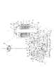
- FIG. 1 is a front sectional view showing a hybrid drive device according to the present invention using a multi-stage automatic transmission.
- Front sectional drawing which shows the principal part.
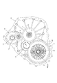
- 1 is a front sectional view showing a hybrid drive device according to the present invention using a continuously variable transmission.
- Front sectional drawing which shows the hybrid drive device which changed partially.
- the hybrid drive device 1 is mounted on an FF type vehicle, and has a first shaft I coaxial with the engine output shaft (crankshaft) 2, an intermediate shaft 4 and an automatic transmission device.
- 3 multi-stage transmission mechanism 5 is arranged, and electric motor 6 is arranged on second axis II different from the first axis.
- a third axis III consisting of a counter shaft 8, a fourth axis IV consisting of a differential device 9, and a deceleration for transmitting power from the electric motor 6 to the input shaft 7 of the automatic transmission 3.
- the case 12 has a fifth axis V consisting of an idle shaft 11 of the gear device, and each of the first to fifth axes is supported by a case 12.
- the case 12 has a cylindrical main case 12a, a clutch housing 12b disposed on the front side (engine side) of the main case, and a rear case 12c disposed on the rear side of the main case. It consists of a tri-section structure that is fixed. When the case 12 is in use, the front end surface of the clutch housing 12b is integrally fixed to an engine (not shown).
- the electric motor 6 includes a stator 13 fixed to the main case 12a and a rotor 16 integrated with the motor output shaft 15.
- the motor output shaft 15 is clutched at its front and rear end portions via ball bearings 14 and 17, respectively.
- the housing 12b and the rear case 12c are rotatably supported with high accuracy.
- the electric motor 13 is preferably a brushless DC motor having a coil embedded on the stator 13 side and a permanent magnet embedded on the rotor 16 side, but may be another motor.
- a rotation angle detector 18 such as a resolver that detects the rotation angle of the electric motor 6 with respect to the rear case is disposed on the rear case 12c side of the output shaft 15.
- a gear (pinion) 19 constituting a second gear is integrally formed on the front side (engine side) of the motor output shaft 15.
- the idle shaft 11 on the fifth shaft V has a rear end side supported rotatably on the main case 12a via a ball bearing 20, and a front end side supported rotatably on the clutch housing 12b via a ball bearing 21. Yes.
- the idle shaft 11 has an idler gear 22 which meshes with the pinion 19 as the second gear and meshes with a gear (first gear) 23 formed on the intermediate shaft 4.
- a reduction gear device is configured to reduce the rotation of the motor output shaft 15 and transmit it to the intermediate shaft 4.
- the idler gear 22 is disposed so as to partially overlap the electric motor 6 in the radial direction when viewed from the side (as viewed from the axial direction).
- the second gear 19 made of a pinion has a small diameter
- the first gear 23 has a large diameter
- the gear ratio transmitted from the second gear 19 to the first gear via the idler gear 22 is increased (a large reduction gear). Ratio).
- the bearing 20 that supports the rear end side of the idle shaft 11 can be disposed close to the output shaft 15 of the electric motor 6, and the idle shaft support portion of the main case 12a does not interfere with the multistage automatic transmission 3 without the interference.
- the multi-stage automatic transmission 3 and the electric motor 6 can be arranged close to the radial direction.
- the intermediate shaft 4 is integrally formed with a gear 23 constituting the first gear on its rear side, and is connected to the input shaft 7 via a spline 26.
- the intermediate shaft 4 is formed so as to extend forward from the gear 23 and is connected to the engine output shaft 2 via a dry clutch 27 and a damper 29 at a front portion thereof.
- the multi-stage automatic transmission device 3 includes an automatic transmission mechanism 5 having a planetary gear unit PU disposed on the first shaft I, as schematically shown in FIG.
- the planetary gear unit PU has a sun gear S1, a sun gear S2, a carrier CR, and a ring gear R as four rotating elements.
- the carrier CR has a long pinion PL that meshes with the sun gear S2 and the ring gear R, and a short that meshes with the sun gear S1. This is a so-called Ravigneaux type planetary gear having a pinion PS in mesh with each other.
- the sun gear S2 of the planetary gear unit PU is connected to the brake B-1 via the brake B-1 and the one-way clutch F-1, and can be fixed to the transmission case 12, and is also connected to the clutch C-3.
- the rotation of the input shaft 7 can be input via the clutch C-3.
- the sun gear S1 is connected to the clutch C-1, and the rotation of the input shaft 7 is freely input.
- the carrier CR is connected to a clutch C-2 to which the rotation of the input shaft 7 is input, and the rotation of the input shaft 7 is freely input via the clutch C-2, and the one-way clutch F- 2 and the brake B-3, the rotation in one direction is restricted with respect to the transmission case 12 via the one-way clutch F-2, and the rotation can be fixed via the brake B-3.
- the ring gear R is connected to a counter drive gear 30, and the counter drive gear 30 meshes with a counter driven gear 31 of the counter shaft 8.
- the counter drive gear 30 is rotatably supported by a partition wall 12c formed in the main case 12a via a bearing 34.
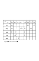
- FIG. 3 is an operation table of the multi-stage automatic transmission 3 described above.
- the multi-stage automatic transmission 3 operates the clutches and the brakes in the combinations shown in the operation table, so that the first forward speed to the fourth forward speed.
- a first gear and a first reverse gear are formed.
- the counter driven gear 31 made of a large diameter gear is integrally fixed to the counter shaft 8 on the third shaft III, and a pinion 32 made of a small diameter gear is integrally formed.
- the counter shaft 8 is supported at the rear end side thereof in a rotatable manner by the main case 12a via a tapered bearing 33, and at the front end side thereof by the clutch housing 12b in a rotatable manner through a tapered bearing 35.
- the supporting wall portion 12b 1 of the clutch housing 12b fitted with the tapered bearing 35, the first gear 23 (not seen from the radial direction) is disposed so as to overlap in the axial direction, the counter shaft 8 forward (engine side ),
- the third axis III portion is shortened.
- the differential device 9 on the fourth axis IV has a differential case 36.
- the differential case 36 is rotatably supported at its rear end side by a main case 12a via a ball bearing 37, and its front end side is a clutch.
- the housing 12b is rotatably supported via a ball bearing 39.
- a shaft 40 orthogonal to the axial direction is mounted inside the differential case 36, and the bevel gears fixed to the left and right axle shafts 42l and 42r mesh with the bevel gear fixed to the shaft 40.
- a differential ring gear 43 is integrally fixed to the differential case 36, and the differential ring gear 43 meshes with the small-diameter counter shaft pinion 32.
- the left and right axle shafts 42l and 42r pass through the differential case 36 and extend to the outside of the case 12, and are connected to the left and right front wheels which are drive wheels.
- the rotation appropriately shifted by the multi-stage automatic transmission 3 is transmitted to the differential case 36 via the counter drive gear 30, the counter driven gear 32, the counter pinion 32, and the diff ring gear 43, and further, the left and right axle shafts 42l as a differential rotation. , 42r.
- the intermediate shaft 4 is one piece mounted on the clutch housing 12b constituting the first support wall.
- the ball bearing 45 is rotatably supported.
- the first gear 23 made of the gear is formed integrally with the intermediate shaft 4 or is integrally formed by an interference fit or the like.
- a bottomed hole 4a having a female spline 26a is formed on the rear end side of the intermediate shaft 4 extending in the forward direction from the first gear 23, and a small-diameter shaft having a male spline 26b on the outer periphery on the front side of the input shaft 7 7a, and the female spline 26a and the male spline 26b are engaged to rotate integrally.
- the first gear 23 is disposed together with the automatic transmission device 5, the counter gears 30 and 32, and the differential device 9 in a lubricating space in the transmission case 12 of the first support wall 12b made of a clutch housing.
- the intermediate shaft 4 protruding forward from 23 penetrates the bearing 45 and the oil seal 46 and protrudes outward from the first support wall 12b.
- the ball bearing 45 is disposed near the first gear 23 of the intermediate shaft 4 and supports the intermediate shaft at a substantially central portion in the axial direction.
- a damper 29 is engaged by a spline 47 with the tip portion of the intermediate shaft 4 protruding outward.
- a drive plate 29b and a driven plate 29c are coupled to each other by a predetermined amount via a coil spring 29a.
- the driven plate 29c is engaged with the intermediate shaft 4 by the spline 47, and the drive plate 29b Further, a cushion plate 27a of the clutch 27 is extended and fixed in the outer diameter direction.
- the clutch 27 has a clutch facing 27b and a pressure plate 27c arranged so as to sandwich the cushion plate 27a.
- the clutch facing 27b is attached to a flywheel 50 fixed to the tip of the engine output shaft 2 with a bolt. They are joined together.
- the pressure plate 27c is urged so as to contact the cushion plate 27a by a spring between the pressure plate 27c and the clutch cover 51 attached to the flywheel 50, and the diaphragm spring 52 is placed on the clutch cover 51 at its radial intermediate portion. Supported as a fulcrum.
- the damper 29 and the clutch 27, more precisely, the cushion plate 27a, the clutch facing 27b, and the pressure plate 27c are arranged so as to be almost completely overlapped in the axial direction, and no axial space dedicated to the damper 29 is required.
- a release bearing 53 is supported on the outer periphery of the annular flange 12k that supports the bearing 45 of the first support wall 12b so as to be movable in the axial direction by a predetermined amount.
- the release bearing 53 is a base end of the inner diameter of the diaphragm spring 52. It is in contact with the part.
- the first support wall 12b is formed with a cylinder 55 formed of an annular recess concentric with the first shaft I (intermediate shaft 4).
- a piston 56 is fitted in the cylinder 55 in an oil-tight manner. is doing.
- the piston 56 and the release bearing 53 are connected by a stepped plate 57, and the clutch 27 is connected / disconnected by an expansion / contraction operation of a hydraulic actuator (hydraulic servo) including the cylinder 55 and the piston 56.
- the hydraulic actuators 55 and 56 are disposed so as to overlap in the axial direction with the bearing 21 that supports the idle shaft 11 and the bearing 45 that supports the intermediate shaft 4 of the first support wall 12b. Is planned. That is, the cylinder 55 is formed by two annular flanges 12l and 12m projecting axially forward from the first support wall 12b and the first support wall 12b serving as a bottom portion therebetween. The outer peripheral side of the annular portion 12m is formed so that a part thereof is in contact with the outer race 21a of the bearing 21 for supporting the idle shaft, thereby shortening the axial direction.
- One ball bearing 59 is interposed between the small-diameter shaft 4b formed at the front end of the intermediate shaft 4 and the recessed hole 2a formed at the front end of the engine output shaft 2, and the intermediate shaft 4 and the engine output.
- the shaft 2 maintains the axial center on the first shaft I through the ball bearing 59.
- a second support wall 12e is disposed adjacent to the rear side of the first gear 23.
- the second support wall 12e includes an oil pump cover 60a formed integrally with the main case 12a and a pump body 60b fixed integrally with the pump cover, and constitutes a fixed support member integrated with the case 12. .
- a pump gear 60c connected to the intermediate shaft 4 and rotating integrally is housed to constitute an oil pump.
- a front end side of the input shaft 7 is rotatably supported by the second support member 12e via a rotation support member 61 having a bush and a needle bearing.
- the rear end side of the input shaft 7 is rotatably supported by the rear case 12c via a bush or the like. Therefore, the input shaft 7 is supported with high accuracy by adopting a double-sided support structure by the case.
- the shaft support structure on the first shaft I is configured as described above, and the intermediate shaft 4 is supported by the first support wall 12b via the ball bearing 45 in the vicinity of the front side of the first gear 23.
- the front end portion of the intermediate shaft 4 is supported and supported by the engine output shaft 2 via a ball bearing 59, so that even if the engine output shaft 2 is slightly shaken due to explosion vibration,
- the intermediate shaft 4 is supported by the two ball bearings 45 and 59 with high accuracy.
- the intermediate shaft 4 is affected by the engine explosion vibration, it is absorbed by the engagement of the first gear 23 and the idler gear 22 and the engagement of the spline 26, and the electric motor output shaft 15 and the automatic transmission 3
- the above influence on the input shaft 7 is small.
- the electric motor 6 is coupled with the stator 13 through the bearings 16 and 17 at both ends of the motor output shaft 15 with high precision support by the case 12 and fixing of the stator 13 in the case 12.
- the air gap G with the rotor 16 can be maintained at a minute interval, and stable power can be generated with high accuracy.
- the torque generated by the electric motor 6 is accurately transmitted to the input shaft 7 of the automatic transmission 5 via the second gear 19, the idler gear 22, the first gear 23, the intermediate shaft 4 and the spline 26.
- the power of the engine output shaft 2 by the engine is transmitted to the intermediate shaft 4 via the dry clutch 27 and the damper 29 and further transmitted to the input shaft 7 of the automatic transmission 5 via the spline 26.
- the pulsation (vibration in the rotational direction) caused by the engine explosion of the engine output shaft 2 is absorbed by the damper 29, and the concentricity between the engine output shaft 2 and the intermediate shaft 4 is always secured by the bearing 59, and the clutch 27, the cushion plate 27a, the clutch facing 27b, and the pressure plate 27c are always brought into frictional contact with high concentricity, so that torque can be transmitted with high accuracy and reliability.
- the input shaft 7 is rotationally supported by the case 12 at both ends with high accuracy, and the rotation of the input shaft 7 is appropriately shifted by the automatic transmission mechanism 5 and left and right through the counter gears 30 and 31 and the differential device 9. Are transmitted to the axle shafts 42l and 42r.
- the hybrid drive device 1 includes an electric motor 6, an idler gear 11, an automatic transmission 3, a counter shaft 8, and a differential device 9 assembled in a main case 12a and a rear case 12c, and an integrated first gear 23 and intermediate shaft 4. Is assembled to the input shaft 7 by spline engagement (26), and the clutch housing 12b is assembled. Then, after assembling the piston 56, the stepped plate 57, and the release bearing 53 to the intermediate shaft 4 protruding from the first support wall 12b of the clutch housing 12, the clutch 27 and the damper 29 including the sub assembly are assembled. As described above, the hybrid drive device 1 can be easily assembled. Further, the hybrid drive device 1 has the ball bearing 59 mounted between the intermediate shaft 4 and the engine output shaft 2, and the clutch housing 12b is mounted on the engine. As a result, the vehicle is assembled as a hybrid drive vehicle.
- FIGS. 1 and 2 portions having the same functions as those of the embodiment shown in FIGS. 1 and 2 are denoted by the same reference numerals and description thereof is omitted.
- the hybrid drive unit 1 as shown in FIG. 4, the electric motor 6, a cone ring type continuously variable automatic transmission (friction type continuously variable transmission) 3 2, a differential device 9, the output shaft of an engine (not shown) an intermediate shaft 4 2 in conjunction with, and a gear transmission device 70.
- the above devices and shafts are housed in a case 12 configured by combining two case members 12g and 12k, and the case 12 is divided into a first space A and a second space B by a partition wall 12i. It is partitioned in an oil-tight manner.
- Cone ring type continuously variable transmission 3 2 includes a friction wheel 72 of the conical shape of the input member, the friction wheel 73 of the same conical shape which is the output member, made of metal ring 75.
- the input member is formed with an axial member integrally with the conical friction wheel 72 at the front and rear, and constitutes the input shaft 7.
- the friction wheels 72 and 73 are arranged in parallel with each other so that the large-diameter portion and the small-diameter portion are reversed in the axial direction, and the ring 75 is inclined so that the friction wheels 22 and 23 face each other. It is arranged so as to be sandwiched between the surfaces and to surround one of the two friction wheels, for example, the input side friction wheel 72.
- a large thrust force acts on at least one of the two friction wheels, and the ring 75 is clamped by a relatively large clamping pressure based on the thrust force. More specifically, a cam mechanism is formed between the output-side friction wheel 73 and the output shaft 8 that is a counter shaft on a surface facing in the axial direction. A thrust force in the direction of arrow D is generated, and a large pinching pressure is generated in the ring 75 between the input side friction wheel 72 supported in a direction opposed to the thrust force.
- the input shaft 7 that is the input side friction wheel 72 has one end (large diameter side) end supported by the first case member (rear case) 12g via the roller bearing 76 and the other side (diameter). The end of the small portion is supported by the partition wall 12 i via a tapered roller bearing 77.
- the output side friction wheel 73 has one end (small diameter side) end supported by the first case member 12g via a roller bearing 79, and the other side (large diameter side) end.
- a (radial) bearing 80 supports the partition wall 12i.
- the output shaft (counter shaft) 8 in which the thrust force in the direction of arrow D described above is applied to the output friction wheel 73 has the other end on the second case member (clutch housing) 12k via a tapered roller bearing 81.
- the other end of the input side friction wheel 72 has an inner race of a bearing 77 sandwiched between a stepped portion and a nut 82, and the output side friction wheel 73 acting on the input side friction wheel 72 via a ring 75 is used.
- a thrust force in the direction of arrow D is carried by the tapered roller bearing 77.
- the reaction force of the thrust force acting on the output side friction wheel 73 acts on the output shaft 73 a in the counter arrow D direction, and the thrust reaction force is carried by the tapered roller bearing 81.
- the ring 75 is moved in the axial direction by an axial movement means such as a ball screw to change the contact position between the input side friction wheel 72 and the output side friction wheel 73, and between the input member 72 and the output member 73.
- the speed ratio is continuously variable.
- the thrust force D corresponding to the transmission torque is canceled by each other in the integrated case 12 via the tapered roller bearings 77 and 81, and does not require an equilibrium force as an external force such as hydraulic pressure.
- a gear (pinion) 32 is formed on the continuously variable transmission output shaft 73a, and the differential ring gear 43 is engaged with the gear 32.
- the motor output gear (second gear) 19, idler gear 22 and first gear (gear) 23, continuously variable transmission output gear (pinion) 32, and diff ring gear (gear) 43 constitute the gear transmission 70. ing.
- the motor output (second gear) 19 and the differential ring gear 43 are arranged so as to overlap in the axial direction, and the first gear 23 and the continuously variable transmission output gear 32 are further connected to the second gear 19 and the differential gear 43.
- the ring gear 43 is disposed so as to overlap in the axial direction.
- the gear 95 that is spline-engaged with the continuously variable transmission output shaft 8a is a parking gear that locks the output shaft at the parking position of the shift lever.
- the intermediate shaft 4 2 is configured in molded or integrally in one piece with the first gear 23 is formed so as to protrude to the front side of the first gear 23.
- the intermediate shaft 4 2, the front side at a position close to (the engine side) is rotatably supported via the one ball bearing 45 to the first case member 12h constituting the first support wall.
- Rear side of the intermediate shaft 4 2 has a small-diameter shaft 4c male splines formed on the outer periphery, the small-diameter shaft 4c is a female spline of the bottomed hole formed in the front end side of the input shaft 7 fitted, the input shaft of the intermediate shaft 4 2 and the continuously variable transmission 3 2 is splined (26).
- the intermediate shaft 4 2 is the outer side of the first support wall 12k through the bearing 45 and an oil seal 46 protrudes third space C, the third space C is an open space, in Figure 4 Although not shown, they are arranged in a dry clutch (27) and a damper (29) similar to those shown in FIG. Between the intermediate shaft 4 2 and the engine output shaft 2, likewise the ball bearings (59) shown in FIG. 2 is interposed so as to ensure the concentricity of both axes.
- Dry clutch 27 shown in FIGS. 1 and 2 has been operated by a hydraulic actuator, the hybrid drive device 1 2 for operating a continuously variable automatic transmission 3 2 by the electric actuator, to operate the dry clutch by electric actuator Is preferred. That is, the release bearing (52) shown in FIG. 2 is interlocked with a ball screw driven by an electric motor via a sector gear and a link.
- the gear transmission 70 is housed in the electric motor 6 and a second space B that is a portion between the first space A and the third space C in the axial direction, and the second space B is
- the partition wall 12i and the second case member 12h constituting the first support wall are partitioned in an oil-tight manner by an oil seal and filled with a predetermined amount of lubricating oil such as ATF.
- the first space A formed by the first case member 12g and the partition wall 12i is also configured to be oil-tight, and the first space A has a shearing force, particularly a shearing force in an extreme pressure state. Is filled with a predetermined amount of large traction oil.
- the first shaft I, the continuously variable transmission output member 73 and the counter shaft 8 that is the output shaft thereof are the third shaft III, the left and right axle shafts 42l and 42r are the fourth shaft IV, and the idler gear shaft 11 is the first shaft I.
- the five axes V these axes are all arranged in parallel and supported by the case 12, and the gears (gears) 19, 22, 23, 32, 43 of the gear transmission 70 are arranged.
- the electric motor 6 and the continuously variable transmission 3 2 is arranged on one axial engine output shaft is connected via a clutch and a damper on the other. Further, the second axis II coaxial with the electric motor 6 is located at the uppermost position, and the fourth axis IV coaxial with the differential device 9 is located at the lowest position, and a part of the ring gear 42 of the differential apparatus 9 is arranged above. It is immersed in an oil reservoir of lubricating oil in the second space B.
- the arrangement relationship shown on the side surface of FIG. 5 is substantially the same even in the hybrid drive device 1 using the multi-stage automatic transmission 3 shown in FIG.
- the present hybrid drive system 1 2 is coupled to the third space C side of the casing 12 to the internal combustion engine, and is used by the output shaft of the engine in conjunction with the intermediate shaft 4 2 via the clutch. Rotation of the intermediate shaft 4 2 power from the engine is transmitted is transmitted to the input side friction wheel 72 of the cone ring type continuously variable transmission 3 2 via a spline 26, the output-side friction wheel further through the ring 75 23.
- the power of the electric motor 6, the second gear 19, is transmitted to the intermediate shaft 4 2 via the idler gear 22 and the first gear 23.
- Rotation of the intermediate shaft 4 2 as in the previous description, the shift in continuously variable through the cone ring type continuously variable transmission 3 2, and the output gear 32, via the ring gear 43 transmitted to the differential device 9 Is done.
- the gear transmission 70 composed of each gear is housed in the second space B filled with lubricating oil, and smoothly transmits power through the lubricating oil when the gears are engaged.
- the differential ring gear 43 disposed at the lower position of the second space B is combined with the large-diameter gear to scoop up the lubricating oil and other gears (gears) 19, 22, 23. , 32 is supplied with a sufficient and sufficient amount of lubricating oil.
- the operation modes of the engine and the electric motor are the same as those using the multi-stage transmission 3 shown in FIG. 1 and those using the continuously variable transmission 3 shown in FIG.
- Various types can be adopted as necessary.
- the clutch 27 is disconnected and the engine is stopped, the engine is started only by the torque of the electric motor 6, and when the vehicle reaches a predetermined speed, the engine is started and accelerated by the power of the engine and the electric motor.
- the electric motor is set in the free rotation or regenerative mode and travels only by the engine. During deceleration and braking, the electric motor is regenerated to charge the battery.
- the clutch may be used as a starting clutch, and may be used to start while using the motor torque as an assist by the power of the engine.
- Electric motor 6 and the second shaft I such as an intermediate shaft 4 2 are disposed in the II axis is another axis, and is disposed at a position overlapping the stepless speed change unit 3 2 and axially, and a gear transmission system 87 is disposed in a relatively narrow space between the continuously variable transmission device 3 2 and the electric motor 6 and the engine, continuously variable transmission needs a space relatively axially as the cone ring type continuously variable transmission a friction wheel type continuously variable transmission and also summarized in compact overall hybrid drive device 1 2, for example, it is possible mounting a relatively narrow installation space such as a small passenger car.
- the gears overlap in the axial direction, and in accordance with the arrangement of the electric motor 6, the axial dimension is made compact, and the idler gear 22 is overlapped in the radial direction of the electric motor 6.
- the continuously variable transmission can be arranged close to each other, and the radial dimension can be made compact.
- the present embodiment is the same as the previous embodiment shown in FIG. 4 except that the transmission form from the motor output gear (second gear) to the first gear is different. Portions are denoted by the same reference numerals and description thereof is omitted.
- the present hybrid drive system 1 3 second gear 19 'and the first gear 23' is made of the sprocket (sprocket wheel) is a motor output gear, both sprockets 19 ', 23' winding is silent chain 22 'between the It has been.
- the second gear 19 ′ is splined to the motor output shaft 15.
- the rotation of the electric motor 6, a second gear 19 of the sprocket ', the silent chain 22' is transmitted to the intermediate shaft 4 2 via the first gear 23 made of, and the sprocket '.
- another chain such as a roller chain may be used.
- an idler gear is not required as compared with the previous embodiment, and the shaft support structure is simplified by that amount (deletion of the fifth shaft V), and the electric motor 6 and the continuously variable transmission 3 2.
- the multi-stage continuously variable transmission uses a forward four-speed gear arranged on one axis, but is not limited to this, and a multi-speed transmission of four or more forward speeds is also a two-shaft.
- a multi-stage transmission device arranged above may be used.
- the cone ring type friction type continuously variable transmission was used as the continuously variable transmission, the present invention is not limited to this, and a continuously variable transmission (not shown) in which a ring is disposed so as to surround both conical friction wheels ( Ring cone type)
- the step transmission, and the input-side and output-side friction discs are arranged so as to be sandwiched between pulley-like friction wheels composed of a pair of sheaves biased toward each other.
- Other friction type continuously variable transmissions such as a continuously variable transmission that shifts and shifts so as to change the inter-axis distance may be used.
- the said embodiment is a hybrid drive device for FF type, this invention is applicable also to a hybrid drive device of FR type.
- the present invention is a hybrid drive device incorporating a friction type continuously variable transmission such as a multi-stage continuously variable transmission or a cone ring continuously variable transmission and an electric motor, and is used by being mounted on an automobile.
- a friction type continuously variable transmission such as a multi-stage continuously variable transmission or a cone ring continuously variable transmission and an electric motor
Landscapes
- Engineering & Computer Science (AREA)
- Mechanical Engineering (AREA)
- General Engineering & Computer Science (AREA)
- Chemical & Material Sciences (AREA)
- Combustion & Propulsion (AREA)
- Transportation (AREA)
- Hybrid Electric Vehicles (AREA)
- Friction Gearing (AREA)
- Arrangement Of Transmissions (AREA)
- Structure Of Transmissions (AREA)
Abstract
Description
前記第1軸(I)上と異なる第2軸(II)上に、電気モータ(6)及び該電気モータ出力軸(15)に設けた第2ギヤ(19)を配置し、
前記エンジン出力軸(2)の回転を前記クラッチ(27)及び前記中間軸(4,42)を介して前記自動変速装置の入力軸(7)に伝達すると共に、前記電気モータ(6)の回転を前記第2ギヤ(19)及び前記第1ギヤ(23)を介して前記自動変速装置の入力軸(7)に伝達してなる、ハイブリッド駆動装置(1,12)において、
前記第1ギヤ(23)のエンジン出力軸側である軸方向前方側及び前記自動変速装置側である軸方向後方側に、それぞれケース(12)と一体の第1支持壁(12a)及び第2支持壁(12e)を配設し、
前記第1ギヤ(23)と前記中間軸(4,42)とは一体にかつ前記第1ギヤの軸方向前方側に延出して前記中間軸が設けられ、該中間軸が、前記第1支持壁(12a)にベアリング(45)を介して回転自在に支持され、
前記第1支持壁(12a)の軸方向前方側にて、前記中間軸(4,42)とエンジン出力軸(2)との間に前記クラッチ(27)が配置され、
前記自動変速装置の入力軸(7)は、その前方側を前記第2支持壁(12e)に回転自在に支持されると共に、前記中間軸(4,42)の後方側にスプライン(26)を介して連結してなる、
ハイブリッド駆動装置にある。
該乾式単板クラッチは、前記第1支持壁(12b)に形成されたシリンダ(55)及び該シリンダに嵌合するピストン(56)からなる油圧アクチュエータにより操作され、
該油圧アクチュエータ(55,56)は、前記中間軸(4)を支持する前記ベアリング(45)と軸方向にオーバラップするように配置されてなる。
前記アイドル歯車を有するアイドル軸(11)は、その軸方向前方が前記第1支持壁(12b)にベアリング(21)を介して回転自在に支持されると共に、その軸方向後方が前記ケースにベアリング(20)を介して回転自在に支持され、
前記油圧アクチュエータ(55,56)が、前記アイドル軸(11)の軸方向前方側を支持する前記ベアリング(21)と軸方向にオーバラップするように配置されてなる。
前記クラッチ(27)と前記中間軸(4)との間に、前記クラッチ(27)と軸方向に少なくとも一部がオーバラップしてダンパ(29)が配置されてなる。
前記多段変速機構(5)は、前記第1軸(I)上に配置され、前記多段変速機構の出力回転をギヤ(30,31)を介して前記カウンタ軸(8)に伝達し、更に該カウンタ軸の回転をギヤ(32,43)を介して前記ディファレンシャル装置(9)に伝達し、
前記カウンタ軸(8)は、その軸方向前方側及び軸方向後方側をベアリング(35,33)を介して前記ケース(12)に回転自在に支持され、
前記カウンタ軸(8)の前記軸方向前方側を支持する前記ケースの支持部(12b1)が、前記第1ギヤ(23)と軸方向にオーバラップするように配置されてなる。
前記無段自動変速装置は、前記入力部材(72)及び前記出力部材(73)がその軸線を互いに平行かつ径大部と径小部が軸方向に逆になるように配置された円錐形状の摩擦車からなり、これら両摩擦車の対向する傾斜面に挟持されるリング(75)を軸方向に移動して変速するコーンリング式無段変速装置(32)であり、
前記円錐形状の摩擦車からなる前記入力部材(72)を前記第1軸(I)上に配置し、前記円錐形状の摩擦車からなる前記出力部材(73)を前記第3軸(III)上に配置し、
前記コーンリング式無段変速装置(32)の前記出力部材(73)の回転を前記カウンタ軸(8)に伝達し、更に該カウンタ軸の回転をギヤを介して前記ディファレンシャル装置(9)に伝達してなる。
2 エンジン出力軸
3 (多段)自動変速装置
32 (無段)自動変速装置
4,42 中間軸
5 多段変速機構
6 電気モータ
7 入力軸
8 カウンタ軸
9 ディファレンシャル装置
11 アイドル軸
12 ケース
12b,12h 第1支持壁(クラッチハウジング)
12e,12i 第2支持壁(オイルポンプ、隔壁)
12b1 支持部
15 モータ出力軸
19,19’ 第2ギヤ
23,23’ 第1ギヤ
21,20,33,35 ベアリング
26 スプライン
27 (乾式単板)クラッチ
29 ダンパ
30,31,32,43 ギヤ
45 ベアリング
55 シリンダ
59 ベアリング
72 入力部材(円錐形状の摩擦車)
73 出力部材(円錐形状の摩擦車)
75 リング
I 第1軸
II 第2軸
III 第3軸
IV 第4軸
V 第5軸
Claims (8)
- エンジン出力軸と同軸の第1軸上に、自動変速装置の入力軸、クラッチ、中間軸及び第1ギヤを配置し、
前記第1軸上と異なる第2軸上に、電気モータ及び該電気モータ出力軸に設けた第2ギヤを配置し、
前記エンジン出力軸の回転を前記クラッチ及び前記中間軸を介して前記自動変速装置の入力軸に伝達すると共に、前記電気モータの回転を前記第2ギヤ及び前記第1ギヤを介して前記自動変速装置の入力軸に伝達してなる、ハイブリッド駆動装置において、
前記第1ギヤのエンジン出力軸側である軸方向前方側及び前記自動変速装置側である軸方向後方側に、それぞれケースと一体の第1支持壁及び第2支持壁を配設し、
前記第1ギヤと前記中間軸とは一体にかつ前記第1ギヤの軸方向前方側に延出して前記中間軸が設けられ、該中間軸が、前記第1支持壁にベアリングを介して回転自在に支持され、
前記第1支持壁の軸方向前方側にて、前記中間軸とエンジン出力軸との間に前記クラッチが配置され、
前記自動変速装置の入力軸は、その前方側を前記第2支持壁に回転自在に支持されると共に、前記中間軸の後方側にスプラインを介して連結してなる、
ハイブリッド駆動装置。 - 前記中間軸の前方側とエンジン出力軸の後方側とが、ベアリングを介して互いに支持されてなる、
請求項1記載のハイブリッド駆動装置。 - 前記クラッチが、乾式単板クラッチであり、
該乾式単板クラッチは、前記第1支持壁に形成されたシリンダ及び該シリンダに嵌合するピストンからなる油圧アクチュエータにより操作され、
該油圧アクチュエータは、前記中間軸を支持する前記ベアリングと軸方向にオーバラップするように配置されてなる、
請求項1又は2記載のハイブリッド駆動装置。 - 前記第1ギヤ及び前記第2ギヤは、歯車であり、アイドラ歯車を介して連動し、
前記アイドル歯車を有するアイドル軸は、その軸方向前方が前記第1支持壁にベアリングを介して回転自在に支持されると共に、その軸方向後方が前記ケースにベアリングを介して回転自在に支持され、
前記油圧アクチュエータが、前記アイドル軸の軸方向前方側を支持する前記ベアリングと軸方向にオーバラップするように配置されてなる、
請求項3記載のハイブリッド駆動装置。 - 前記クラッチが、乾式単板クラッチであり、
前記クラッチと前記中間軸との間に、前記クラッチと軸方向に少なくとも一部がオーバラップしてダンパが配置されてなる、
請求項1ないし4のいずれか記載のハイブリッド駆動装置。 - 前記自動変速装置は、多数のギヤによる伝動経路をクラッチにより切換える多段変速機構を有する多段自動変速装置である、
請求項1ないし5のいずれか記載のハイブリッド駆動装置。 - 第3軸上に配置されたカウンタ軸と、第4軸上に配置されたディファレンシャル装置と、を備え、
前記多段変速機構は、前記第1軸上に配置され、前記多段変速機構の出力回転をギヤを介して前記カウンタ軸に伝達し、更に該カウンタ軸の回転をギヤを介して前記ディファレンシャル装置に伝達し、
前記カウンタ軸は、その軸方向前方側及び軸方向後方側をベアリングを介して前記ケースに回転自在に支持され、
前記カウンタ軸の前記軸方向前方側を支持する前記ケースの支持部が、前記第1ギヤと軸方向にオーバラップするように配置されてなる、
請求項6記載のハイブリッド駆動装置。 - 前記自動変速装置は、前記入力軸に駆動連結する入力部材及び出力部材を有し、これら入力部材と出力部材との接触位置を変更すると共に、該接触位置に介在する油膜の剪断力により前記入力部材の回転を無段に変速して前記出力部材に伝達する無段自動変速装置である、
請求項1ないし5のいずれか記載のハイブリッド駆動装置。
Priority Applications (3)
| Application Number | Priority Date | Filing Date | Title |
|---|---|---|---|
| US13/379,153 US8549959B2 (en) | 2009-09-18 | 2010-09-17 | Hybrid drive device |
| CN201080031917.8A CN102470743B (zh) | 2009-09-18 | 2010-09-17 | 混合动力驱动装置 |
| DE112010002982T DE112010002982T5 (de) | 2009-09-18 | 2010-09-17 | Hybridantriebssystem |
Applications Claiming Priority (2)
| Application Number | Priority Date | Filing Date | Title |
|---|---|---|---|
| JP2009-218120 | 2009-09-18 | ||
| JP2009218120 | 2009-09-18 |
Publications (2)
| Publication Number | Publication Date |
|---|---|
| WO2011034191A1 true WO2011034191A1 (ja) | 2011-03-24 |
| WO2011034191A9 WO2011034191A9 (ja) | 2012-02-02 |
Family
ID=43757119
Family Applications (2)
| Application Number | Title | Priority Date | Filing Date |
|---|---|---|---|
| PCT/JP2010/005104 Ceased WO2011033719A1 (ja) | 2009-09-18 | 2010-08-18 | ハイブリッド駆動装置 |
| PCT/JP2010/066262 Ceased WO2011034191A1 (ja) | 2009-09-18 | 2010-09-17 | ハイブリッド駆動装置 |
Family Applications Before (1)
| Application Number | Title | Priority Date | Filing Date |
|---|---|---|---|
| PCT/JP2010/005104 Ceased WO2011033719A1 (ja) | 2009-09-18 | 2010-08-18 | ハイブリッド駆動装置 |
Country Status (5)
| Country | Link |
|---|---|
| US (2) | US20110070995A1 (ja) |
| JP (2) | JP5120432B2 (ja) |
| CN (2) | CN102378702A (ja) |
| DE (2) | DE112010000470T5 (ja) |
| WO (2) | WO2011033719A1 (ja) |
Cited By (2)
| Publication number | Priority date | Publication date | Assignee | Title |
|---|---|---|---|---|
| WO2013099953A1 (ja) * | 2011-12-26 | 2013-07-04 | アイシン・エィ・ダブリュ株式会社 | ハイブリッド駆動装置 |
| US20130284557A1 (en) * | 2011-03-17 | 2013-10-31 | Aisin Aw Co., Ltd. | Vehicle driving force transmission device |
Families Citing this family (28)
| Publication number | Priority date | Publication date | Assignee | Title |
|---|---|---|---|---|
| WO2011111544A1 (ja) * | 2010-03-08 | 2011-09-15 | アイシン・エィ・ダブリュ株式会社 | ハイブリッド駆動装置 |
| WO2012137446A1 (en) | 2011-04-06 | 2012-10-11 | Panasonic Corporation | Thermoelectric conversion element module and method of manufacturing the same |
| AT512710B1 (de) * | 2011-09-30 | 2014-06-15 | Steyr Motors Gmbh | Antriebseinheit mit einer elektrischen maschine |
| US8936120B2 (en) * | 2011-12-29 | 2015-01-20 | Kawasaki Jukogyo Kabushiki Kaisha | Utility vehicle having a front electric motor |
| CN103847493B (zh) * | 2012-11-30 | 2018-04-27 | 施泰尔发动机有限公司 | 具有电机的驱动单元 |
| DE102012024426A1 (de) * | 2012-12-14 | 2014-06-18 | Getrag Getriebe- Und Zahnradfabrik Hermann Hagenmeyer Gmbh & Cie Kg | Lageranordnung, Hybrid-Getriebeanordnung und Verfahren zu deren Montage |
| US9062744B2 (en) * | 2013-03-13 | 2015-06-23 | American Axle & Manufacturing, Inc. | Two-speed drive module |
| CN104070980B (zh) * | 2013-03-28 | 2017-02-08 | 比亚迪股份有限公司 | 一种集成化混合动力总成机体及应用其的汽车 |
| JP6156632B2 (ja) * | 2013-06-07 | 2017-07-05 | 三菱自動車工業株式会社 | 車両のトランスアクスル装置 |
| ITPD20130292A1 (it) * | 2013-10-23 | 2015-04-24 | Antonio Francisco Cesaroni | Gruppo di trazione per veicoli ibridi |
| DE102013018057B4 (de) * | 2013-11-28 | 2022-08-25 | Rolls-Royce Solutions GmbH | Gehäuseelement für einen Antrieb und Antrieb |
| CN103818232B (zh) * | 2014-03-13 | 2017-02-01 | 河南科技大学 | 一种并联式混合动力汽车及其驱动系统 |
| CN105644335B (zh) | 2014-11-14 | 2020-02-28 | 上海汽车集团股份有限公司 | 车辆用双电机动力系统和双电机混合动力系统 |
| CN106143102B (zh) | 2014-11-18 | 2019-07-16 | 上海汽车集团股份有限公司 | 车辆混合动力驱动系统及其变速器 |
| CN105673780B (zh) | 2014-11-18 | 2019-08-06 | 上海汽车集团股份有限公司 | 车辆混合动力驱动系统及其变速器 |
| CN105620460B (zh) | 2014-11-18 | 2019-07-16 | 上海汽车集团股份有限公司 | 用于混合动力车辆变速器的控制系统和方法 |
| CN105667491B (zh) | 2014-11-18 | 2019-07-16 | 上海汽车集团股份有限公司 | 用于混合动力车辆变速器的控制系统和方法 |
| CN106274464B (zh) | 2015-05-29 | 2019-09-10 | 上海汽车集团股份有限公司 | 纯电动车辆的双电机动力系统和控制方法 |
| CN106274460B (zh) | 2015-05-29 | 2019-12-10 | 上海汽车集团股份有限公司 | 双电机电动车辆的电驱变速箱控制装置和方法 |
| JP6759027B2 (ja) * | 2015-10-20 | 2020-09-23 | 株式会社エクセディ | ハイブリッド駆動装置 |
| JP6961327B2 (ja) * | 2016-04-01 | 2021-11-05 | 日産自動車株式会社 | ギア装置 |
| US10156289B2 (en) * | 2017-03-07 | 2018-12-18 | Meritor do Brasil Sistemas Automotivos Ltda. | Axle assembly having multiple clutch collars |
| US11654769B2 (en) * | 2020-09-30 | 2023-05-23 | Gkn Automotive Limited | Driveline unit housing |
| CN112196963B (zh) * | 2020-10-09 | 2021-06-11 | 绍兴柯桥尼希纺织科技有限公司 | 一种传动装置转速调节控制机构 |
| US11772743B2 (en) * | 2022-02-18 | 2023-10-03 | Joseph Francis Keenan | System and method for bicycle transmission |
| DE102024104353A1 (de) * | 2024-02-16 | 2025-08-21 | Schaeffler Technologies AG & Co. KG | Hybridantriebsstrangvorrichtung mit Zentriermittel |
| JP2025126081A (ja) * | 2024-02-17 | 2025-08-28 | ダイハツ工業株式会社 | 変速機 |
| CN118928015B (zh) * | 2024-08-09 | 2025-10-03 | 重庆智主传动产业技术研究院有限公司 | 内置传动人控倒车锥度离合式自适应变速电驱动系统 |
Citations (6)
| Publication number | Priority date | Publication date | Assignee | Title |
|---|---|---|---|---|
| JPH06107007A (ja) * | 1992-09-28 | 1994-04-19 | Mazda Motor Corp | 動力伝達装置の潤滑構造 |
| JPH09156388A (ja) * | 1995-12-06 | 1997-06-17 | Toyota Motor Corp | ハイブリッド駆動装置 |
| JP2006183760A (ja) * | 2004-12-27 | 2006-07-13 | Nissan Motor Co Ltd | ハイブリッド自動車の変速機 |
| JP2008501899A (ja) * | 2004-06-03 | 2008-01-24 | プジョー シトロエン オートモビル エス アー | パラレルハイブリッド方式駆動系用の伝達要素 |
| JP2009101729A (ja) * | 2007-10-19 | 2009-05-14 | Aisin Aw Co Ltd | ハイブリッド駆動装置 |
| JP2009208702A (ja) * | 2008-03-06 | 2009-09-17 | Nissan Motor Co Ltd | ハイブリッド駆動装置 |
Family Cites Families (12)
| Publication number | Priority date | Publication date | Assignee | Title |
|---|---|---|---|---|
| KR950005359B1 (ko) * | 1991-03-25 | 1995-05-23 | 마쓰다 가부시끼가이샤 | 차량의 동력전달 장치구조 |
| ATA6192A (de) * | 1992-01-16 | 1997-05-15 | Avl Verbrennungskraft Messtech | Antriebsvorrichtung antriebsvorrichtung |
| US5415603A (en) * | 1992-04-01 | 1995-05-16 | Kabushikikaisha Equos Research | Hydraulic control system for hybrid vehicle |
| US5509329A (en) * | 1994-10-24 | 1996-04-23 | General Motors Corporation | Casing assembly adapted for either manual or automatic transmissions |
| US5558589A (en) * | 1995-07-20 | 1996-09-24 | General Motors Corporation | Two-mode, compound-split, electro-mechanical vehicular transmission |
| US5571058A (en) * | 1995-08-08 | 1996-11-05 | General Motors Corporation | Four-mode, input-split, paralell, hybrid transmission |
| JP4002991B2 (ja) * | 2001-05-17 | 2007-11-07 | トヨタ自動車株式会社 | ハイブリッド車両用無段変速機の制御装置 |
| CN1578890B (zh) * | 2002-09-30 | 2010-05-26 | 乌尔里克·罗斯 | 传动机构 |
| CN101153649B (zh) * | 2002-09-30 | 2013-06-12 | 乌尔里克·罗斯 | 传动机构 |
| JP4699206B2 (ja) | 2002-09-30 | 2011-06-08 | ロース,ウルリヒ | 歯車装置 |
| JP4052270B2 (ja) * | 2004-03-18 | 2008-02-27 | トヨタ自動車株式会社 | 変速機の制御装置 |
| JP4900693B2 (ja) * | 2006-11-27 | 2012-03-21 | アイシン・エィ・ダブリュ株式会社 | ハイブリッド駆動装置 |
-
2010
- 2010-08-05 US US12/851,058 patent/US20110070995A1/en not_active Abandoned
- 2010-08-18 CN CN2010800150988A patent/CN102378702A/zh active Pending
- 2010-08-18 DE DE112010000470T patent/DE112010000470T5/de not_active Withdrawn
- 2010-08-18 WO PCT/JP2010/005104 patent/WO2011033719A1/ja not_active Ceased
- 2010-09-17 US US13/379,153 patent/US8549959B2/en not_active Expired - Fee Related
- 2010-09-17 WO PCT/JP2010/066262 patent/WO2011034191A1/ja not_active Ceased
- 2010-09-17 JP JP2010210234A patent/JP5120432B2/ja not_active Expired - Fee Related
- 2010-09-17 DE DE112010002982T patent/DE112010002982T5/de not_active Ceased
- 2010-09-17 CN CN201080031917.8A patent/CN102470743B/zh not_active Expired - Fee Related
- 2010-09-17 JP JP2010210233A patent/JP5163722B2/ja not_active Expired - Fee Related
Patent Citations (6)
| Publication number | Priority date | Publication date | Assignee | Title |
|---|---|---|---|---|
| JPH06107007A (ja) * | 1992-09-28 | 1994-04-19 | Mazda Motor Corp | 動力伝達装置の潤滑構造 |
| JPH09156388A (ja) * | 1995-12-06 | 1997-06-17 | Toyota Motor Corp | ハイブリッド駆動装置 |
| JP2008501899A (ja) * | 2004-06-03 | 2008-01-24 | プジョー シトロエン オートモビル エス アー | パラレルハイブリッド方式駆動系用の伝達要素 |
| JP2006183760A (ja) * | 2004-12-27 | 2006-07-13 | Nissan Motor Co Ltd | ハイブリッド自動車の変速機 |
| JP2009101729A (ja) * | 2007-10-19 | 2009-05-14 | Aisin Aw Co Ltd | ハイブリッド駆動装置 |
| JP2009208702A (ja) * | 2008-03-06 | 2009-09-17 | Nissan Motor Co Ltd | ハイブリッド駆動装置 |
Cited By (4)
| Publication number | Priority date | Publication date | Assignee | Title |
|---|---|---|---|---|
| US20130284557A1 (en) * | 2011-03-17 | 2013-10-31 | Aisin Aw Co., Ltd. | Vehicle driving force transmission device |
| WO2013099953A1 (ja) * | 2011-12-26 | 2013-07-04 | アイシン・エィ・ダブリュ株式会社 | ハイブリッド駆動装置 |
| JP2013132934A (ja) * | 2011-12-26 | 2013-07-08 | Aisin Aw Co Ltd | ハイブリッド駆動装置 |
| CN103796858A (zh) * | 2011-12-26 | 2014-05-14 | 爱信艾达株式会社 | 混合动力驱动设备 |
Also Published As
| Publication number | Publication date |
|---|---|
| JP5163722B2 (ja) | 2013-03-13 |
| US20110070995A1 (en) | 2011-03-24 |
| US20120096985A1 (en) | 2012-04-26 |
| WO2011033719A1 (ja) | 2011-03-24 |
| JP5120432B2 (ja) | 2013-01-16 |
| JP2011084266A (ja) | 2011-04-28 |
| CN102378702A (zh) | 2012-03-14 |
| WO2011034191A9 (ja) | 2012-02-02 |
| JP2011084267A (ja) | 2011-04-28 |
| US8549959B2 (en) | 2013-10-08 |
| DE112010000470T5 (de) | 2012-05-24 |
| DE112010002982T5 (de) | 2012-12-27 |
| CN102470743A (zh) | 2012-05-23 |
| CN102470743B (zh) | 2014-08-20 |
Similar Documents
| Publication | Publication Date | Title |
|---|---|---|
| JP5163722B2 (ja) | ハイブリッド駆動装置 | |
| JP6052435B2 (ja) | ハイブリッド駆動装置 | |
| KR100996132B1 (ko) | 하이브리드 구동장치 및 이를 탑재한 자동차 | |
| JP4708467B2 (ja) | 車両の駆動装置 | |
| JP5246466B2 (ja) | ハイブリッド駆動装置 | |
| US9677646B2 (en) | Drive device that transfers rotation of at least one of a rotary electric machine and an internal combustion engine to an oil pump | |
| US10041570B2 (en) | Power transmission device | |
| JP5821620B2 (ja) | ハイブリッド駆動装置 | |
| WO2015105165A1 (ja) | 自動変速機 | |
| JP2012225370A (ja) | 変速装置 | |
| WO2012132839A1 (ja) | 自動変速機 | |
| JP3860593B2 (ja) | ハイブリッド駆動装置並びにそれを搭載した自動車 | |
| JP2020190280A (ja) | 動力伝達経路切換装置および2段変速機 | |
| JP2012225369A (ja) | 変速装置 | |
| CN109804183B (zh) | 用于机动车的变速器 | |
| JP2015123813A (ja) | ハイブリッド駆動装置 | |
| JP5039647B2 (ja) | 動力伝達装置 | |
| JP4516655B2 (ja) | 発進クラッチ | |
| JP4921825B2 (ja) | 車両用駆動力伝達装置 | |
| JP2010038221A (ja) | 車両の変速機 | |
| JP2016168976A (ja) | 車両用駆動装置 | |
| JP2006151054A (ja) | 車両の駆動力伝達装置 |
Legal Events
| Date | Code | Title | Description |
|---|---|---|---|
| WWE | Wipo information: entry into national phase |
Ref document number: 201080031917.8 Country of ref document: CN |
|
| 121 | Ep: the epo has been informed by wipo that ep was designated in this application |
Ref document number: 10817304 Country of ref document: EP Kind code of ref document: A1 |
|
| WWE | Wipo information: entry into national phase |
Ref document number: 8513/CHENP/2011 Country of ref document: IN |
|
| WWE | Wipo information: entry into national phase |
Ref document number: 13379153 Country of ref document: US |
|
| WWE | Wipo information: entry into national phase |
Ref document number: 112010002982 Country of ref document: DE Ref document number: 1120100029822 Country of ref document: DE |
|
| 122 | Ep: pct application non-entry in european phase |
Ref document number: 10817304 Country of ref document: EP Kind code of ref document: A1 |