WO2011034154A1 - ステント - Google Patents
ステント Download PDFInfo
- Publication number
- WO2011034154A1 WO2011034154A1 PCT/JP2010/066100 JP2010066100W WO2011034154A1 WO 2011034154 A1 WO2011034154 A1 WO 2011034154A1 JP 2010066100 W JP2010066100 W JP 2010066100W WO 2011034154 A1 WO2011034154 A1 WO 2011034154A1
- Authority
- WO
- WIPO (PCT)
- Prior art keywords
- stent
- cells
- cell
- arc
- connecting portion
- Prior art date
- Legal status (The legal status is an assumption and is not a legal conclusion. Google has not performed a legal analysis and makes no representation as to the accuracy of the status listed.)
- Ceased
Links
Images


Classifications
-
- A—HUMAN NECESSITIES
- A61—MEDICAL OR VETERINARY SCIENCE; HYGIENE
- A61F—FILTERS IMPLANTABLE INTO BLOOD VESSELS; PROSTHESES; DEVICES PROVIDING PATENCY TO, OR PREVENTING COLLAPSING OF, TUBULAR STRUCTURES OF THE BODY, e.g. STENTS; ORTHOPAEDIC, NURSING OR CONTRACEPTIVE DEVICES; FOMENTATION; TREATMENT OR PROTECTION OF EYES OR EARS; BANDAGES, DRESSINGS OR ABSORBENT PADS; FIRST-AID KITS
- A61F2/00—Filters implantable into blood vessels; Prostheses, i.e. artificial substitutes or replacements for parts of the body; Appliances for connecting them with the body; Devices providing patency to, or preventing collapsing of, tubular structures of the body, e.g. stents
- A61F2/82—Devices providing patency to, or preventing collapsing of, tubular structures of the body, e.g. stents
- A61F2/86—Stents in a form characterised by the wire-like elements; Stents in the form characterised by a net-like or mesh-like structure
- A61F2/90—Stents in a form characterised by the wire-like elements; Stents in the form characterised by a net-like or mesh-like structure characterised by a net-like or mesh-like structure
- A61F2/91—Stents in a form characterised by the wire-like elements; Stents in the form characterised by a net-like or mesh-like structure characterised by a net-like or mesh-like structure made from perforated sheets or tubes, e.g. perforated by laser cuts or etched holes
- A61F2/915—Stents in a form characterised by the wire-like elements; Stents in the form characterised by a net-like or mesh-like structure characterised by a net-like or mesh-like structure made from perforated sheets or tubes, e.g. perforated by laser cuts or etched holes with bands having a meander structure, adjacent bands being connected to each other
- A61F2002/9155—Adjacent bands being connected to each other
- A61F2002/91558—Adjacent bands being connected to each other connected peak to peak
-
- A—HUMAN NECESSITIES
- A61—MEDICAL OR VETERINARY SCIENCE; HYGIENE
- A61F—FILTERS IMPLANTABLE INTO BLOOD VESSELS; PROSTHESES; DEVICES PROVIDING PATENCY TO, OR PREVENTING COLLAPSING OF, TUBULAR STRUCTURES OF THE BODY, e.g. STENTS; ORTHOPAEDIC, NURSING OR CONTRACEPTIVE DEVICES; FOMENTATION; TREATMENT OR PROTECTION OF EYES OR EARS; BANDAGES, DRESSINGS OR ABSORBENT PADS; FIRST-AID KITS
- A61F2230/00—Geometry of prostheses classified in groups A61F2/00 - A61F2/26 or A61F2/82 or A61F9/00 or A61F11/00 or subgroups thereof
- A61F2230/0002—Two-dimensional shapes, e.g. cross-sections
- A61F2230/0004—Rounded shapes, e.g. with rounded corners
- A61F2230/0013—Horseshoe-shaped, e.g. crescent-shaped, C-shaped, U-shaped
Definitions
- the present invention relates to a stent used for improving the narrowing of an opening in a living body such as a blood vessel, and particularly to a stent having excellent durability and bending flexibility.
- the term “stent” means a device formed of a biocompatible material used to expand an opening in a living body such as a blood vessel and maintain the size of the expanded opening.
- the stent is introduced with the inflatable balloon to the desired location on the body, and when the balloon is inflated, the stent expands, thereby expanding the constricted opening.
- FIG. 7 As a conventionally known stent structure, there is a structure shown in FIG. 7 (the structure described in FIG. 1 of Patent Documents 1 and 2).
- a plurality of cells 11 are connected in the circumferential direction, and a plurality of the cells 11 are arranged so as to surround the central axis C1 of the stent 15 to form an annular unit 12, and adjacent to each other.
- the opposing cells 11, 11 'of the matching annular units 12, 12' are connected by a substantially S-shaped connecting portion 14, respectively.
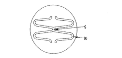
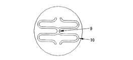
- FIGS. 3 and 5 the structure shown in FIGS. 3 and 5 (the structure described in FIGS. 1 and 3 of Patent Document 3) is known.
- a first annular unit 8 composed of a first cell group in which a plurality of first cells 7 are connected in the circumferential direction, and a second cell in which a plurality of second cells 7 ′ are connected in the circumferential direction.
- a group of second annular units 8 ′ are alternately arranged so as to surround the central axis C1 of the stent 6, and a part of the adjacent cells of the adjacent first and second annular units 8, 8 ′.
- the shapes of the first cell 7 and the second cell 7 ′ are symmetrical with respect to the axial direction of the stent 6 around the connecting portion 9, and the cells of the connecting portion 9 are It is slightly longer than the unconnected cell.
- the cells 16, 16 ′ are partially connected by the connecting portion 17, and the length of the cell is constant.
- the length of the connecting portion 17 is about 0.2 mm.
- the cells 18 and 18 ' are formed by bending a CoCr alloy wire in a zigzag shape, and the connecting portion 19 is partially connected by welding. Yes.
- a stent treatment method has been rapidly popularized to restore blood flow by mechanically dilating an arterial lesion that has been narrowed due to the progression of arteriosclerosis using a balloon catheter, and placing a metal stent in the lumen of the affected area. It has become.
- a stent used for such treatment needs to satisfy the following three requirements. First, the closed stent is placed on a balloon attached to the distal end portion of the balloon catheter, and is passed through the patient's tortuous artery along a guide wire that has been inserted into the artery in advance. Transport to the constriction. Thus, the stent must be flexible in order to pass through the narrow and tortuous artery.
- the expanded stent must be durable enough to withstand repeated bending loads caused by the heartbeat, with sufficient strength to support the arterial wall or keep the stenosis open. .
- the total length of the expanded stent becomes shorter than the length of the closed state. If the length of the expanded stent is shortened, the lesion may not be covered as per the doctor's treatment plan. Therefore, it is desirable that the stent before and after expansion has a small dimensional change.
- the present inventor has found that the stents disclosed in Patent Documents 1 and 2 have uniform flexibility and sufficient strength to maintain the open state of the stenosis.
- the maximum stress is generated at the top of the bending portion 13 constituting the S-shaped connecting portion, and the bending durability is determined as a result of the fatigue durability test. It was found that the bending durability of the top portion of 13 is inferior to the bending durability at the substantially straight portions constituting the opposing cells 11, 11 ′ and the S-shaped connecting portion.
- Patent Document 3 has sufficient bending durability when subjected to a bending load as a result of physical property evaluation.
- the standard expansion pressure during stent expansion is disclosed in Patent Documents 1 and 2. It was found to be higher than 7 stents and difficult to open. Therefore, the stent disclosed in Patent Document 3 has a problem in terms of expandability. Further, the other company stents shown in FIGS. 8 and 9 which are currently on the market also have a difficulty in expandability, similar to the stent disclosed in Patent Document 3.
- the object of the present invention is to have a high flexibility capable of easily transporting through a narrow and slender artery, excellent expandability at the time of stent expansion, and support the artery wall to maintain the open state of the stenosis.
- An object of the present invention is to provide a stent that has sufficient strength to withstand the repeated bending load of an artery caused by the heartbeat.
- the present inventors have found that the maximum stress in the approximately arc portion of the cell is repeated due to the heartbeat after stent expansion by the balloon and after placement of the stent.
- the maximum stress caused by bending load greatly depends on the structure of the cell connection part.
- the optimization of the structure of the connection part between the opposing cells makes a breakthrough in bending durability without impairing expandability. Has been found to improve.
- the inventors have made the radius of curvature of the top of the arc constituting the substantially arc portion of the cell larger than the radius of curvature of the tangential circle formed at the arc-side end of the substantially linear portion of the cell.
- the stress and strain are almost uniformly distributed, the load applied to the cell is reduced most, and the bending durability is excellent, and the standard expansion pressure is lowered and the expansion uniformity is also reduced. It was confirmed that the present invention was excellent and the present invention was reached.
- annular unit formed by connecting a plurality of cells each having a substantially U-shaped shape having a substantially straight portion and a substantially arc portion and opened to one end along the axial direction is provided in the axial direction.
- a tubular body is formed by arranging a plurality of parts and being connected by a connecting portion, and the tubular body is a stent that is radially expandable from the inside thereof,
- a first annular unit consisting of a first cell group connecting a plurality of first cells in the circumferential direction
- a second annular unit consisting of a second cell group connecting a plurality of second cells in the circumferential direction.
- the shapes of the first cell and the second cell are symmetrical with respect to the axial direction of the stent around the connecting portion, and the adjacent first and second cells
- the connecting portion is formed by connecting the substantially arc portions of the opposing cells.
- the radius of curvature of the apex of the arc forming the substantially arc portion of the cell in substantially all cells constituting the stent is 1.1 to 1.5 times the radius of curvature of the tangential circle of the approximately straight portion of the cell. It is the stent characterized by being in the range.
- the curvature radius of the apex of the substantially arc portion of the cell is in a range of 1.2 to 1.4 times the curvature radius of the tangent circle of the substantially straight portion of the cell.
- the lengths of the substantially straight portions of both cells connected by the connecting portion are the same and slightly longer than the length of the substantially straight portion of the cells of the non-connecting portion. .
- the substantially straight line portion of the cells connected by the connecting portion is approximately 10 to 25% longer than the substantially straight line portion of the non-connected portion cell. It is about 1 to 0.3 mm.
- each of the annular units is composed of 6 to 10 cells, and preferably 1 to 3 cells among them form a connecting portion between the cells. .
- the connecting portion may be constituted by a short linear object between the substantially arc portions of the opposing cells, but the substantially arc portions of the opposing cells are directly connected to each other.
- the connecting portion is constituted, and it is particularly preferable that the connecting portion has a structure in which the apexes of the central arcs of the substantially arc portions of the opposing cells share each other. It is preferable that the width and thickness of the cell and the connecting portion are constant.
- the material forming the stent is preferably a cobalt chromium alloy or stainless steel, and a material made of a biodegradable metal or a biodegradable polymer is preferable.
- a material made of a biodegradable metal or a biodegradable polymer is preferable.
- the biodegradable metal pure magnesium, magnesium alloy, pure iron, or iron alloy is preferable.
- the substantially annular S-shaped connecting portion is eliminated and the adjacent annular units face each other. Only a part of the cells are connected to each other, and the curvature radius of the top of the arc forming the substantially arc portion of the cell in substantially all the cells constituting the stent is set to the arc of the substantially straight portion of the cell.
- the present invention by connecting only a part of the opposing cells and making the substantially arc shape of the cell in the connecting portion as described above, the standard expansion pressure is lowered, so that expandability is impaired. In addition, the durability against the bending load can be dramatically improved.
- FIG. 2 is a partially enlarged view of FIG. It is a top view which shows an example of the conventional partial link stent.
- FIG. 4 is an enlarged view of FIG. It is a top view which shows another example of the conventional partial link stent.
- FIG. 6 is an enlarged view of FIG. 5.
- It is a top view of the conventional all link stent.
- It is a schematic plan view which shows the connection between the annular units of another company's stent.
- It is a schematic plan view which shows the connection between the annular units of another company's stent.
- It is a conceptual diagram of the strut which comprises a cell. It is the schematic which shows the sample for a bending test.
- FIG. 1 is a plan view showing an example of the stent 1 of the present invention.
- FIG. 2 is an enlarged view showing a connecting portion of the stent 1 shown in FIG.
- the circumferential direction is such that the cells 2, 2 ′ having a substantially U-shape opened to one end along the axial direction surround the central axis C ⁇ b> 1 of the stent 1.
- a plurality of annular units 3 and 3 ′ are formed by being connected to each other, and a plurality of the annular units 3 and 3 ′ are arranged in the axial direction and connected by a connecting portion 4 to form a tubular body.
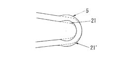
- the tubular body can be extended in the radial direction from the inside thereof, and the U-shaped cell is composed of a substantially linear portion and a substantially arc portion 5.
- a first annular unit 3 composed of a first cell group in which a plurality of first cells 2 are connected in the circumferential direction and a second ring unit in which a plurality of second cells 2 ′ are connected in the circumferential direction.
- a tubular body is formed by alternately connecting the second annular units 3 ′ composed of cell groups, and the first cell 2 and the second cell 2 ′ are symmetrical with respect to the connecting portion 4. is doing. Only some of the cells of the annular units 3 and 3 ′ that are opposed to each other are connected by a connecting portion 4 (partial link type). Since only some of the cells are connected to each other, the flexibility of the stent can be obtained compared to the case where all the cells are connected (all link type).
- connection structure in the connection portion 4 may be such that the tops of the substantially arc portions of the opposing cells may be connected with a short linear object of 0.1 to 0.3 mm, but preferably the connection portion 4
- the substantially straight line portions of the connected cells are slightly longer than the substantially straight line portions of the non-connected cells, and the top of the substantially arc portion 5 of one cell is directly connected to the substantially arc portion 5 of the other cell. It is preferable that they are integrated in contact.
- maximum stress may be generated at the center of the linear connecting part, which may be disadvantageous in terms of bending durability.
- the maximum stress is generated at four locations around the connecting portion (see reference numeral 22 in FIG. 2), the level of the maximum stress can be reduced, and the bending durability can be improved.
- a gap is formed between the cells 2 and 2 'between the substantially arc portions of the cells, and the substantially straight portion of the cell of the connecting portion is not a distance corresponding to the gap. It is slightly longer than the substantially straight part of the cell of the connection part. The presence of this slight gap in the unconnected portion prevents cells from overlapping when the stent is bent or contracted, and the opposing cells when the stent is bent. Will not win.
- the substantially straight line portion of the cells connected by the connecting portion is approximately 10 to 25% longer than the substantially straight line portion of the cells of the non-connected portion.
- the gap between the cells 2 and 2 'in the unconnected portion is too small to sufficiently obtain the above effect, and if it exceeds 25%, the space becomes large and blood vessels are uniformly supported.
- it is disadvantageous in terms of expansion uniformity if the length of the cell in the connecting portion is longer than the length of the cell in the non-connecting portion, and stress is easily applied to the connecting portion.
- the radius of curvature of the top of the arc constituting the substantially arc portion 5 of the cell constituting the stent is a tangent circle 21 formed at the arc-side ends of the two substantially straight portions of the cells 2 and 2 ′. , 21 'and 1.1 to 1.5 times the radius of curvature, preferably 1.2 to 1.4 (see FIG. 13).
- the standard expansion pressure is lower than that of the conventional stent, and the safety factor of the expansion operation is improved.
- the radius of curvature is less than 1.1 times, it is difficult to reduce the level of the maximum stress generated at the top of the substantially arc portion, and if the radius of curvature exceeds 1.5 times the radius of curvature, the substantially straight portion and the substantially arc portion of the cell Stress is generated at the boundary, and the effect of improving durability cannot be obtained.
- the ratio exceeds 1.5 times the top of the arc becomes too large, and the arc portions may interfere with each other when crimping the stent, which is not preferable.
- the cells 2 and 2 ' have a greater radial support force when the stent is expanded at an obtuse angle with respect to the central axis C1.
- the angle ⁇ formed by the two substantially linear portions of the expanded cell approaches 120 °, the radial support force of the stent increases. That is, in the design of the stent, when the cell is expanded to at least ⁇ 2.5 mm, the angle ⁇ after cell expansion is preferably designed to be at least 50 ° or more.
- the size of the stent (the length when the stent is not expanded, the diameter when the stent is not expanded) is not particularly limited, and may be the same as a conventionally used stent.
- the diameter is about 9 to 40 mm, and the diameter when not expanded is about 0.8 to 2 mm.
- the length of one annular unit of the stent is preferably about 0.5 to 3.0 mm.
- the length of one connecting part (the length of the gap in the axial direction between cells in the non-connecting part) is preferably about 0.05 to 1 mm, more preferably 0.1 to 0.3 mm.
- the number of cells 2, 2 ′ arranged in the circumferential direction is preferably 4 or more.
- the diameter after expansion is ⁇ 3.0 mm or more, it is preferable to arrange 6 or more, usually 6 to 12 pieces. Further, it is preferable that the annular units 3 and 3 ′ are arranged such that both of the annular units are combined in the stent axial direction with 6 or more, usually 6 to 12. Furthermore, in the stent axial direction, 3 or more per 10 mm, usually 4 to 8 are arranged, and when the target diameter for stent expansion (standard diameter, eg, ⁇ 3.0, ⁇ 4.0) is reached, for example, as described above In addition, the angle ⁇ after cell expansion should be designed to be at least 50 ° or more, usually 60 ° to 120 °.
- Designing the target diameter so as to exceed 120 ° is effective for the radiation supporting force of the stent, but the deformation amount of the substantially circular arc portion 5 becomes large and causes a problem.
- the shortening of the total length (four shortening) of the stent accompanying expansion becomes large, which causes problems such as difficulty in positioning during stent placement, which is not preferable.
- the shape of the struts (two straight portions) of the cells 2 and 2 ' is preferably formed in a radially symmetrical shape as shown in FIG. 10 with respect to the center line C1 in the stent axial direction.
- the thickness of the cell 2 is usually constant.
- the width of the cell 2 is usually 80 to 110 ⁇ m and the thickness is 70 to 90 ⁇ m.
- the width of the cell 2 is usually 80 to 150 ⁇ m and the thickness is 100 to 150 ⁇ m.
- annular unit 3 and the connection part 4 are constant.
- the constant width and thickness make it easy to control the dimensions during processing and polishing, and the constant width and thickness means that the cross-sectional area is constant and the bending moment in the same direction at any position. Tend to be the same, and the flexibility of the stent tends not to be affected by the direction.
- the cells are directly connected to each other, and the vertices of the center arc portions 20 and 20 'of the cells facing each other at the connecting portion overlap to make the thickness and the width constant, thereby enhancing expansion uniformity (see FIG. 2).
- the connecting portion 4 by configuring the connecting portion 4 as described above, since stress is not concentrated on the connecting portion 4, durability can be dramatically improved, and flexibility and expandability can be improved. There is an advantage that there is no decrease.
- the connecting portions 4 are not provided in all of the individual cells 2 and 2 '(partial link type), the cells 2 and 2' are respectively provided even when the diameter of the stent 1 is reduced during delivery to the blood vessel. They do not overlap with each other in the radial direction of the stent.
- the number of connecting portions 4 of the cells 2, 2 ′ constituting each annular unit 3, 3 ′ needs to be formed in the circumferential direction of the stent 1. .
- the number of connecting portions is selected according to the number of cells.
- the diameter of the stent is 3 to 9 mm, and the number of cells is 6 to 10.
- the number of connecting portions in the case of the number is preferably 1 to 3.
- a connecting portion is formed only in a part between a plurality of opposing cells 2 and 2 ′, and the remaining cells 2 and 2 ′ are not connected but form a non-connecting portion. Due to the presence of this unconnected portion, the entire stent 1 becomes more flexible, the delivery performance to the branched blood vessel is improved, and the stress on the arc portion forming the connecting portion is dispersed, so that the connecting portion is continuous without a gap. Thus, the durability is improved as compared with the stent disposed in the same manner.
- the stent of the present invention is manufactured from a metal pipe made of stainless steel such as SUS316, shape memory alloy such as Ni—Ti alloy, Cu—Al—Mn alloy, titanium alloy, tantalum alloy, cobalt chromium alloy or the like.
- the stent of the present invention may be manufactured from a metal (biodegradable metal) that can be decomposed in vivo.
- the biodegradable metal include pure magnesium, magnesium alloy, pure iron, and iron alloy.
- the magnesium alloy contains magnesium as a main component and contains at least one element selected from a biocompatible element group consisting of Zr, Y, Ti, Ta, Nd, Nb, Zn, Ca, Al, Li, and Mn. Those that do are preferred.
- the iron alloy includes iron as a main component, Mn, Co, Ni, Cr, Cu, Cd, Pb, Sn, Th, Zr, Ag, Au, Pd, Pt, Re, Si, Ca, Li, Al, Zn It preferably contains at least one element selected from the group of biocompatible elements consisting of Fe, C and S. Examples include those containing 88-99.8% iron, 0.1-7% chromium and 0-3.5% nickel and less than 5% other metals.
- the stent of the present invention comprises a biodegradable polymer such as polylactic acid, polyglycolic acid, poly (lactic acid-glycolic acid), poly (lactic acid- ⁇ -caprolactone), poly (glycolic acid- ⁇ -caprolactone), poly (A biodegradable high toughness polymer such as butylene succinate) may be made of a composite biodegradable polymer dispersed in a biodegradable matrix polymer such as polylactic acid. These biodegradable polymers may be stretched and oriented. Furthermore, a biodegradable polymer may be coated on a metal that can be decomposed in vivo.
- a biodegradable polymer such as polylactic acid, polyglycolic acid, poly (lactic acid-glycolic acid), poly (lactic acid- ⁇ -caprolactone), poly (glycolic acid- ⁇ -caprolactone), poly ( A biodegradable high toughness polymer such as butylene succinate) may be made of a composite biodegradable
- the stent of the present invention has a characteristic shape as described above, but a stent having such a shape can be integrally manufactured by laser processing.
- the manufacturing process by laser processing will be described.
- a tool path in laser processing is created using CAM based on the shape data of the designed stent.
- the tool path is set in consideration of the fact that the stent shape can be maintained after laser cutting and that no chips remain.
- laser processing is performed on the metal or polymer thin film meat tube. Control the generation of burrs and select machining conditions with the goal of high speed and high quality machining.
- the surface is made glossy using electropolishing, and the edge portion is finished in a smooth shape.
- a post-processing process after laser cutting is important.
- the oxide on the metal cut surface is first dissolved with an acid solution, and then electropolishing is performed.
- electropolishing a metal plate such as a stent or stentless is immersed in an electrolytic solution, and the two metals are connected via a DC power source.
- the stent on the anode side is dissolved to obtain a polishing effect.
- the stent manufactured by the above laser processing method can form a network structure as designed, so that high flexibility and radiation support force are sufficiently secured, vasodilatability is enhanced, and foreshortening and flare phenomenon are suppressed. It is possible to provide a stent that does not cut cells or the like during use.
- the present invention should not be limited by an example.
- the expansion pressure, bending durability time, flexibility, for shortening value, recoil value, and maximum strain are those measured by the following methods.
- a 3.0 mm diameter stent was inserted into a silicon tube having an inner diameter of 3.0 mm and an outer diameter of 4.0 mm, and the expansion pressure was measured when the inner diameter of the stent was expanded to 3 mm with a balloon through physiological saline.
- the stent was inserted into a silicon tube having an inner diameter of 3.0 mm and an outer diameter of 4.0 mm, and the inner diameter of the stent was expanded to 3 mm through physiological saline.
- the length of the stent after expansion was measured, and the reduction ratio with respect to the length of the stent before expansion was calculated to obtain a for shortening value.
- the stent was inserted into a silicon tube having an inner diameter of 3.0 mm and an outer diameter of 4.0 mm, and the inner diameter of the stent was expanded to 3 mm with a balloon through physiological saline. Thereafter, the balloon was removed, the inner diameter of the stent after the balloon was removed, and the recoil value was calculated by the following equation (1).
- the stent (Example 1) shown below was used as the stent of the present invention, and compared with the stents of Comparative Examples 1 to 4 shown below. The results are shown in Table 1 and FIG.
- Each of the stents used in Example 1 and Comparative Examples 1 to 4 has a length of 17.4 mm, an inner diameter of 1.0 mm when contracted, and an inner diameter of 3.0 mm when expanded, and the cells 2 and 2 ′ and the connecting portion 4 are formed.
- the width of the portion to be fixed is 100 ⁇ m and the thickness is constant 70 ⁇ m, both of which are stents made of cobalt chromium alloy.
- Example 1 The curvature radius of the top of the arc constituting the substantially arc portion 5 of all the cells of the connected portion and the unconnected portion of the stent shown in FIG. 1 is set to the radius of curvature R0.15 ⁇ of the tangential arc of the substantially straight portion 2.
- the curvature radius is 1.3 times R0.20 ⁇ (Fig. 2).
- the conventional stent (all link stent) of Comparative Example 1 shown in FIG. 7 includes a first annular unit 12 composed of a first cell group in which a plurality of first cells 11 are connected in the circumferential direction, and the first cell. And second annular units 12 ′ composed of a plurality of second cells 11 ′ having a symmetrical shape when viewed from the radial direction are alternately arranged, and all of the opposing cells are connected to form a substantially tubular body. .
- the adjacent annular units 12, 12 ′ are all connected by a connecting portion 14, can be extended in the circumferential direction from the inside of the tubular body, and connect a plurality of cells 11 in the circumferential direction.
- Comparative Example 4 The stent of Comparative Example 4 shown in FIG. 14 is the same as the conventional stent of Comparative Example 1 shown in FIG. 7, but the opposed cells 11 and 11 ′ of the annular units 12 and 12 ′ are connected by a substantially S-shaped connecting part 14. Instead of the all-link type connecting portion, a partial link type in which every other connecting portion is provided.
- Example 1 As shown in Table 1, as a result of the test, the durability of the partial link stents (Example 1, Comparative Examples 2, 3, and 4) is greater than that of the entire link stent (Comparative Example 1). The reason for this is that the cell space of the partial link is deformed (there are few constraint points and the degree of freedom), so that the load applied to the link is reduced, and it is estimated that the bending durability is superior to that of all link stents. In comparison of the partial link stent groups, the durability of Example 1 is greater than that of other partial link stents. The reason for this is presumed that when Example 1 was subjected to a bending load, the maximum strain was reduced (see FIG.
- Example 12 the load applied to the cell was most reduced, and the bending durability was excellent. Further, it was confirmed that the standard expansion pressure of Example 1 was 8 atm, lower than the standard expansion pressure of Comparative Examples 2 and 3, 9 atm, and the expansion uniformity and flexibility were excellent. Moreover, for shortening, recoil, etc. are equivalent to conventional stents, and are excellent in balance between durability and performance.
- FIG. 2 is an enlarged view of the arc portion 5 and the connecting portion 4 of the cell of the stent according to the first embodiment.
- Such a structure is more durable and provides a stent in which the cells are uniformly deformed and the stress and strain of the arc portion 5 and the connecting portion 4 are substantially uniform when subjected to a bending load.
- the cell arc portion 5 and the connection portion 4 have a relatively low stress / comparison compared to the bent portion between the cells of Comparative Example 1 and the arc portion 10 and the connection portion 9 of Comparative Examples 2 and 3. It has a structure subject to strain. Furthermore, the curvature radius of the top of the arc constituting the cell arc part 5 is 1.1 to 1.5 times the curvature radius of the tangential circle formed at the arc-side end of the substantially straight part of the cells 2 and 2 ′. Since the cell has a radius and the cells are connected by the connecting portion 4, the maximum stress and strain are minimized, resulting in excellent bending fatigue durability, bending flexibility, and expansion. Good uniformity.
- the present invention greatly contributes to the stent manufacturing technology by providing a stent having a structure excellent in durability against bending load and flexibility, the industrial applicability is extremely large. Furthermore, since the stent of the present invention can be manufactured integrally by laser processing, the industrial applicability is great from this point.
Landscapes
- Health & Medical Sciences (AREA)
- Engineering & Computer Science (AREA)
- Biomedical Technology (AREA)
- Heart & Thoracic Surgery (AREA)
- Life Sciences & Earth Sciences (AREA)
- Cardiology (AREA)
- Oral & Maxillofacial Surgery (AREA)
- Transplantation (AREA)
- Physics & Mathematics (AREA)
- Vascular Medicine (AREA)
- Optics & Photonics (AREA)
- Animal Behavior & Ethology (AREA)
- General Health & Medical Sciences (AREA)
- Public Health (AREA)
- Veterinary Medicine (AREA)
- Media Introduction/Drainage Providing Device (AREA)
- Prostheses (AREA)
Priority Applications (5)
| Application Number | Priority Date | Filing Date | Title |
|---|---|---|---|
| US13/395,581 US8882827B2 (en) | 2009-09-17 | 2010-09-16 | Stent |
| EP10817267.7A EP2478876A4 (en) | 2009-09-17 | 2010-09-16 | STENT |
| IN2511DEN2012 IN2012DN02511A (https=) | 2009-09-17 | 2010-09-16 | |
| CN2010800412209A CN102497838A (zh) | 2009-09-17 | 2010-09-16 | 支架 |
| JP2011531975A JP5684133B2 (ja) | 2009-09-17 | 2010-09-16 | ステント |
Applications Claiming Priority (2)
| Application Number | Priority Date | Filing Date | Title |
|---|---|---|---|
| JP2009-215464 | 2009-09-17 | ||
| JP2009215464 | 2009-09-17 |
Publications (1)
| Publication Number | Publication Date |
|---|---|
| WO2011034154A1 true WO2011034154A1 (ja) | 2011-03-24 |
Family
ID=43758754
Family Applications (1)
| Application Number | Title | Priority Date | Filing Date |
|---|---|---|---|
| PCT/JP2010/066100 Ceased WO2011034154A1 (ja) | 2009-09-17 | 2010-09-16 | ステント |
Country Status (6)
| Country | Link |
|---|---|
| US (1) | US8882827B2 (https=) |
| EP (1) | EP2478876A4 (https=) |
| JP (1) | JP5684133B2 (https=) |
| CN (1) | CN102497838A (https=) |
| IN (1) | IN2012DN02511A (https=) |
| WO (1) | WO2011034154A1 (https=) |
Cited By (1)
| Publication number | Priority date | Publication date | Assignee | Title |
|---|---|---|---|---|
| CN102813566A (zh) * | 2012-04-24 | 2012-12-12 | 冯海全 | 冠脉支架 |
Families Citing this family (9)
| Publication number | Priority date | Publication date | Assignee | Title |
|---|---|---|---|---|
| CN106901881B (zh) * | 2009-10-30 | 2019-06-18 | 科迪斯公司 | 具有改进的柔性和耐用性的脉管内装置 |
| US20110282428A1 (en) * | 2010-05-13 | 2011-11-17 | Boston Scientific Scimed, Inc. | Biodegradable composite stent |
| EP2849688B1 (en) | 2012-05-14 | 2023-08-23 | C. R. Bard, Inc. | Uniformly expandable stent |
| USD723165S1 (en) | 2013-03-12 | 2015-02-24 | C. R. Bard, Inc. | Stent |
| CN103462734A (zh) * | 2013-09-18 | 2013-12-25 | 深圳市金瑞凯利生物科技有限公司 | 冠脉血管支架及其制作方法 |
| DE102014016588A1 (de) | 2014-11-11 | 2016-05-12 | medicut Stent Technology GmbH | Stentprothese |
| JP6667758B2 (ja) * | 2015-11-26 | 2020-03-18 | 株式会社 日本医療機器技研 | 生体吸収性ステント |
| CN105902331A (zh) * | 2016-04-08 | 2016-08-31 | 南京永明医疗器械有限公司 | 一种血管支架及其制备方法 |
| EP3578142B1 (en) | 2017-02-01 | 2022-03-23 | Kake Educational Institution Okayama University Of Science | Bioabsorbable stent |
Citations (6)
| Publication number | Priority date | Publication date | Assignee | Title |
|---|---|---|---|---|
| JPH03145720A (ja) | 1989-10-31 | 1991-06-20 | Oki Electric Ind Co Ltd | 化合物半導体の成長方法及びこれに使用するシリコン基板 |
| JP3654627B2 (ja) | 2000-04-20 | 2005-06-02 | 川澄化学工業株式会社 | ステント |
| JP3663192B2 (ja) | 2001-10-16 | 2005-06-22 | 川澄化学工業株式会社 | ステント |
| JP3145720U (ja) * | 2008-08-06 | 2008-10-16 | 株式会社日本ステントテクノロジー | ステント |
| WO2008126894A1 (ja) * | 2007-04-12 | 2008-10-23 | Kaneka Corporation | ステント |
| JP2009082245A (ja) * | 2007-09-27 | 2009-04-23 | Terumo Corp | 生体内留置用ステントおよび生体器官拡張器具 |
Family Cites Families (11)
| Publication number | Priority date | Publication date | Assignee | Title |
|---|---|---|---|---|
| DE29708879U1 (de) * | 1997-05-20 | 1997-07-31 | Jomed Implantate GmbH, 72414 Rangendingen | Koronarer Stent |
| JP3605388B2 (ja) | 2001-10-16 | 2004-12-22 | 川澄化学工業株式会社 | ステント |
| EP1503700B1 (en) * | 2002-05-08 | 2012-09-26 | Abbott Laboratories | Endoprosthesis having foot extensions |
| US20060121080A1 (en) * | 2002-11-13 | 2006-06-08 | Lye Whye K | Medical devices having nanoporous layers and methods for making the same |
| JP4797473B2 (ja) | 2005-07-11 | 2011-10-19 | ニプロ株式会社 | 拡張性の優れた柔軟なステント |
| EP1752113B1 (de) * | 2005-08-10 | 2008-12-10 | Axetis AG | Rohrförmige Stützprothese mit sich seitlich überlappenden Krümmungsbögen |
| US8388673B2 (en) * | 2008-05-02 | 2013-03-05 | Abbott Cardiovascular Systems Inc. | Polymeric stent |
| EP2186492B1 (en) | 2007-09-27 | 2012-08-15 | Terumo Kabushiki Kaisha | Stent and living organ dilator |
| EP3505142B1 (en) * | 2007-10-19 | 2020-10-28 | CeloNova Biosciences, Inc. | Implantable and lumen-supporting stents |
| CN101357089A (zh) | 2008-09-12 | 2009-02-04 | 西北有色金属研究院 | 一种生物可降解镁合金血管内支架的制作方法 |
| CA2757627C (en) * | 2009-04-10 | 2014-10-28 | Ev3 Inc. | Implants having high fatigue resistance, implant delivery systems, and methods of use |
-
2010
- 2010-09-16 JP JP2011531975A patent/JP5684133B2/ja not_active Expired - Fee Related
- 2010-09-16 WO PCT/JP2010/066100 patent/WO2011034154A1/ja not_active Ceased
- 2010-09-16 IN IN2511DEN2012 patent/IN2012DN02511A/en unknown
- 2010-09-16 US US13/395,581 patent/US8882827B2/en not_active Expired - Fee Related
- 2010-09-16 EP EP10817267.7A patent/EP2478876A4/en not_active Withdrawn
- 2010-09-16 CN CN2010800412209A patent/CN102497838A/zh active Pending
Patent Citations (6)
| Publication number | Priority date | Publication date | Assignee | Title |
|---|---|---|---|---|
| JPH03145720A (ja) | 1989-10-31 | 1991-06-20 | Oki Electric Ind Co Ltd | 化合物半導体の成長方法及びこれに使用するシリコン基板 |
| JP3654627B2 (ja) | 2000-04-20 | 2005-06-02 | 川澄化学工業株式会社 | ステント |
| JP3663192B2 (ja) | 2001-10-16 | 2005-06-22 | 川澄化学工業株式会社 | ステント |
| WO2008126894A1 (ja) * | 2007-04-12 | 2008-10-23 | Kaneka Corporation | ステント |
| JP2009082245A (ja) * | 2007-09-27 | 2009-04-23 | Terumo Corp | 生体内留置用ステントおよび生体器官拡張器具 |
| JP3145720U (ja) * | 2008-08-06 | 2008-10-16 | 株式会社日本ステントテクノロジー | ステント |
Non-Patent Citations (1)
| Title |
|---|
| See also references of EP2478876A4 * |
Cited By (1)
| Publication number | Priority date | Publication date | Assignee | Title |
|---|---|---|---|---|
| CN102813566A (zh) * | 2012-04-24 | 2012-12-12 | 冯海全 | 冠脉支架 |
Also Published As
| Publication number | Publication date |
|---|---|
| JP5684133B2 (ja) | 2015-03-11 |
| JPWO2011034154A1 (ja) | 2013-02-14 |
| EP2478876A4 (en) | 2014-07-16 |
| IN2012DN02511A (https=) | 2015-08-28 |
| CN102497838A (zh) | 2012-06-13 |
| US8882827B2 (en) | 2014-11-11 |
| EP2478876A1 (en) | 2012-07-25 |
| US20120172974A1 (en) | 2012-07-05 |
Similar Documents
| Publication | Publication Date | Title |
|---|---|---|
| JP5684133B2 (ja) | ステント | |
| JP5243577B2 (ja) | 生体内留置用ステント | |
| AU2006338440B2 (en) | Endoluminal prosthesis | |
| JP4871692B2 (ja) | 生体内留置用ステントおよび生体器官拡張器具 | |
| US7651524B2 (en) | Flexible stent | |
| US20130096669A1 (en) | Partially annealed stent | |
| JP5573911B2 (ja) | 生体留置用ステント | |
| JP3145720U (ja) | ステント | |
| JP3146103U (ja) | ステント | |
| CN202568545U (zh) | 一种冠脉支架 | |
| JP2007144108A (ja) | 生体内留置用ステント | |
| JP4654361B2 (ja) | ステント | |
| JP6628263B2 (ja) | 生体吸収性ステント | |
| JP5267457B2 (ja) | ステント | |
| JP4846414B2 (ja) | 生体内留置用ステントおよび生体器官拡張器具 | |
| JP2016059504A (ja) | 柔軟性が向上したステント | |
| JP2016059506A (ja) | 病変部に正確に留置することができるステント | |
| JP4835113B2 (ja) | ステント | |
| JP2016059505A (ja) | 拡張均一性が向上したステント | |
| JP2010233933A (ja) | 生体内留置用ステントおよび生体器官拡張器具 | |
| JP5612985B2 (ja) | ステント及びそれを備えたステントシステム、並びに、ステント製造方法 | |
| CN223696096U (zh) | 一种具有显影特性的编织支架 | |
| JP2017094017A (ja) | ステント | |
| EP4212133A1 (en) | Stent and method for producing stent | |
| RU2393820C2 (ru) | Внутрипросветный протез |
Legal Events
| Date | Code | Title | Description |
|---|---|---|---|
| WWE | Wipo information: entry into national phase |
Ref document number: 201080041220.9 Country of ref document: CN |
|
| 121 | Ep: the epo has been informed by wipo that ep was designated in this application |
Ref document number: 10817267 Country of ref document: EP Kind code of ref document: A1 |
|
| WWE | Wipo information: entry into national phase |
Ref document number: 2011531975 Country of ref document: JP Ref document number: 13395581 Country of ref document: US Ref document number: 2010817267 Country of ref document: EP |
|
| NENP | Non-entry into the national phase |
Ref country code: DE |
|
| WWE | Wipo information: entry into national phase |
Ref document number: 2511/DELNP/2012 Country of ref document: IN |