WO2011030472A1 - スマートグリッド及びマイクログリッド向け総合監視制御システム - Google Patents
スマートグリッド及びマイクログリッド向け総合監視制御システム Download PDFInfo
- Publication number
- WO2011030472A1 WO2011030472A1 PCT/JP2009/070840 JP2009070840W WO2011030472A1 WO 2011030472 A1 WO2011030472 A1 WO 2011030472A1 JP 2009070840 W JP2009070840 W JP 2009070840W WO 2011030472 A1 WO2011030472 A1 WO 2011030472A1
- Authority
- WO
- WIPO (PCT)
- Prior art keywords
- amount
- power generation
- information
- generation output
- distributed power
- Prior art date
Links
Images


Classifications
-
- H—ELECTRICITY
- H02—GENERATION; CONVERSION OR DISTRIBUTION OF ELECTRIC POWER
- H02J—CIRCUIT ARRANGEMENTS OR SYSTEMS FOR SUPPLYING OR DISTRIBUTING ELECTRIC POWER; SYSTEMS FOR STORING ELECTRIC ENERGY
- H02J3/00—Circuit arrangements for ac mains or ac distribution networks
- H02J3/38—Arrangements for parallely feeding a single network by two or more generators, converters or transformers
-
- H—ELECTRICITY
- H02—GENERATION; CONVERSION OR DISTRIBUTION OF ELECTRIC POWER
- H02J—CIRCUIT ARRANGEMENTS OR SYSTEMS FOR SUPPLYING OR DISTRIBUTING ELECTRIC POWER; SYSTEMS FOR STORING ELECTRIC ENERGY
- H02J3/00—Circuit arrangements for ac mains or ac distribution networks
- H02J3/001—Methods to deal with contingencies, e.g. abnormalities, faults or failures
- H02J3/0012—Contingency detection
-
- H—ELECTRICITY
- H02—GENERATION; CONVERSION OR DISTRIBUTION OF ELECTRIC POWER
- H02J—CIRCUIT ARRANGEMENTS OR SYSTEMS FOR SUPPLYING OR DISTRIBUTING ELECTRIC POWER; SYSTEMS FOR STORING ELECTRIC ENERGY
- H02J3/00—Circuit arrangements for ac mains or ac distribution networks
- H02J3/12—Circuit arrangements for ac mains or ac distribution networks for adjusting voltage in ac networks by changing a characteristic of the network load
- H02J3/14—Circuit arrangements for ac mains or ac distribution networks for adjusting voltage in ac networks by changing a characteristic of the network load by switching loads on to, or off from, network, e.g. progressively balanced loading
-
- H—ELECTRICITY
- H02—GENERATION; CONVERSION OR DISTRIBUTION OF ELECTRIC POWER
- H02J—CIRCUIT ARRANGEMENTS OR SYSTEMS FOR SUPPLYING OR DISTRIBUTING ELECTRIC POWER; SYSTEMS FOR STORING ELECTRIC ENERGY
- H02J3/00—Circuit arrangements for ac mains or ac distribution networks
- H02J3/38—Arrangements for parallely feeding a single network by two or more generators, converters or transformers
- H02J3/381—Dispersed generators
-
- H—ELECTRICITY
- H02—GENERATION; CONVERSION OR DISTRIBUTION OF ELECTRIC POWER
- H02J—CIRCUIT ARRANGEMENTS OR SYSTEMS FOR SUPPLYING OR DISTRIBUTING ELECTRIC POWER; SYSTEMS FOR STORING ELECTRIC ENERGY
- H02J3/00—Circuit arrangements for ac mains or ac distribution networks
- H02J3/38—Arrangements for parallely feeding a single network by two or more generators, converters or transformers
- H02J3/46—Controlling of the sharing of output between the generators, converters, or transformers
-
- H—ELECTRICITY
- H02—GENERATION; CONVERSION OR DISTRIBUTION OF ELECTRIC POWER
- H02J—CIRCUIT ARRANGEMENTS OR SYSTEMS FOR SUPPLYING OR DISTRIBUTING ELECTRIC POWER; SYSTEMS FOR STORING ELECTRIC ENERGY
- H02J2300/00—Systems for supplying or distributing electric power characterised by decentralized, dispersed, or local generation
- H02J2300/10—The dispersed energy generation being of fossil origin, e.g. diesel generators
-
- H—ELECTRICITY
- H02—GENERATION; CONVERSION OR DISTRIBUTION OF ELECTRIC POWER
- H02J—CIRCUIT ARRANGEMENTS OR SYSTEMS FOR SUPPLYING OR DISTRIBUTING ELECTRIC POWER; SYSTEMS FOR STORING ELECTRIC ENERGY
- H02J2310/00—The network for supplying or distributing electric power characterised by its spatial reach or by the load
- H02J2310/50—The network for supplying or distributing electric power characterised by its spatial reach or by the load for selectively controlling the operation of the loads
- H02J2310/56—The network for supplying or distributing electric power characterised by its spatial reach or by the load for selectively controlling the operation of the loads characterised by the condition upon which the selective controlling is based
- H02J2310/58—The condition being electrical
- H02J2310/60—Limiting power consumption in the network or in one section of the network, e.g. load shedding or peak shaving
-
- Y—GENERAL TAGGING OF NEW TECHNOLOGICAL DEVELOPMENTS; GENERAL TAGGING OF CROSS-SECTIONAL TECHNOLOGIES SPANNING OVER SEVERAL SECTIONS OF THE IPC; TECHNICAL SUBJECTS COVERED BY FORMER USPC CROSS-REFERENCE ART COLLECTIONS [XRACs] AND DIGESTS
- Y02—TECHNOLOGIES OR APPLICATIONS FOR MITIGATION OR ADAPTATION AGAINST CLIMATE CHANGE
- Y02B—CLIMATE CHANGE MITIGATION TECHNOLOGIES RELATED TO BUILDINGS, e.g. HOUSING, HOUSE APPLIANCES OR RELATED END-USER APPLICATIONS
- Y02B70/00—Technologies for an efficient end-user side electric power management and consumption
- Y02B70/30—Systems integrating technologies related to power network operation and communication or information technologies for improving the carbon footprint of the management of residential or tertiary loads, i.e. smart grids as climate change mitigation technology in the buildings sector, including also the last stages of power distribution and the control, monitoring or operating management systems at local level
- Y02B70/3225—Demand response systems, e.g. load shedding, peak shaving
-
- Y—GENERAL TAGGING OF NEW TECHNOLOGICAL DEVELOPMENTS; GENERAL TAGGING OF CROSS-SECTIONAL TECHNOLOGIES SPANNING OVER SEVERAL SECTIONS OF THE IPC; TECHNICAL SUBJECTS COVERED BY FORMER USPC CROSS-REFERENCE ART COLLECTIONS [XRACs] AND DIGESTS
- Y04—INFORMATION OR COMMUNICATION TECHNOLOGIES HAVING AN IMPACT ON OTHER TECHNOLOGY AREAS
- Y04S—SYSTEMS INTEGRATING TECHNOLOGIES RELATED TO POWER NETWORK OPERATION, COMMUNICATION OR INFORMATION TECHNOLOGIES FOR IMPROVING THE ELECTRICAL POWER GENERATION, TRANSMISSION, DISTRIBUTION, MANAGEMENT OR USAGE, i.e. SMART GRIDS
- Y04S20/00—Management or operation of end-user stationary applications or the last stages of power distribution; Controlling, monitoring or operating thereof
- Y04S20/20—End-user application control systems
- Y04S20/222—Demand response systems, e.g. load shedding, peak shaving
Definitions
- the present invention relates to a comprehensive monitoring and control system for smart grids and microgrids.
- the electric power that we always use is generated at various power plants (nuclear power, thermal power, hydropower, etc.), and high-quality power is stably supplied to customers through the backbone and distribution systems.
- the existing power system has a large-scale centralized power plant for the purpose of stably supplying a large amount of electricity, so the lead time from planning to the start of operation is long, and the location of the large-scale power plant There are limits to the improvement of the total energy efficiency including the heat recovery rate because there are many places far from the demand place in the area that satisfies the conditions.
- a microgrid can obtain high total energy efficiency by placing a power supply in a demand area.
- a power source configuration that combines a controllable power source and a power source that is difficult to control, such as a naturally variable power source, it is possible to construct a network that does not affect the commercial network while considering the environment. Become a “good citizen” who can contribute to the power system by minimizing the impact on the power system by creating a small-scale network and system by mutually complementing the features of each distributed power source. Is the “microgrid”.
- microgrids can be expected as one of various measures such as power peak cut and load leveling. Reports on microgrids include the evaluation of the same amount of interconnected tidal currents in consideration of smooth operation during normal operation, or supply and demand control functions such as how to balance supply and demand using distributed power sources and power storage devices There are many contents regarding (patent documents 1 to 4).
- DAS distribution automation system
- EMS Energy Management System
- DSM Demand Side Management
- control such as patents 5 to 11
- equipment management such as patents 5 to 11
- construction planning and construction work support that was performed in the distribution management system
- DMS Distribution Management System
- the power capacity of the current commercial network (distribution system level) is guaranteed to be enough to supply all one distribution line at one power supply terminal, except during summer demand peaks. Therefore, even if system switching is performed when an accident occurs or work is performed, it is easy to secure another power source, and the frequency of occurrence of supply trouble sections is very low.
- the power source is a set of a plurality of small distributed power sources, so there are sections where the power supply is insufficient when the system is switched even when the power supply is satisfied during normal operation. Is likely to occur. Therefore, even if the conventional interchange method based on the assumption that the power supply capacity is sufficiently secured is applied to the microgrid, it is assumed that a large number of supply hampering sections occur.
- the power generation output of the distributed power source and the demand load adjustment plan must be established, and the work execution system must be established.
- the operation state equivalent to that during normal operation must be maintained. Don't be.
- the grid state assumed at the time of work planning and the system state at the time of work execution Are often different.
- the present invention has been made in view of the above circumstances, and an object of the present invention is to provide a comprehensive monitoring and control system capable of appropriately accommodating electric power when an accident occurs in a smart grid or a microgrid or when work is performed. .
- An integrated supervisory control system is a comprehensive supervisory control system that monitors and controls the power generation output of each distributed power source and the load of a demand facility in a smart grid or a microgrid.
- Measurement value monitoring means for acquiring information indicating the power generation output amount and information indicating the current load amount of each demand facility, at least information indicating the rated power generation capacity and power generation output adjustable amount of each distributed power source, Information indicating the contract power amount and load adjustable amount, information indicating the priority of each distributed power source for determining the distributed power source for adjusting the power generation output amount, and determining the demand facility for adjusting the load amount
- Customer information management means for managing information indicating the priority of each demand facility for the microgrid or smart grid When an accident occurs in the power system, at least information acquired by the measurement value monitoring means and information managed by the customer information management means are used, and the total power generation output amount of each distributed power source and each demand facility And an abnormal-time accommodation procedure creating means for creating an accommodation procedure for making the total load amount coincide with each other.
- An integrated supervisory control system is a comprehensive supervisory control system that monitors and controls the power generation output of each distributed power source and the load of a demand facility in a smart grid or a microgrid.
- Measurement value monitoring means for storing information indicating power, information indicating at least the rated power generation capacity and power generation output adjustable amount of each distributed power source, information indicating the contract power amount and load adjustable amount of each demand facility, and power generation output Information indicating the priority of each distributed power source for determining the distributed power source for adjusting the capacity and the demand facility for adjusting the load amount
- Customer information management means for managing information indicating the priority of each demand facility for determination, information stored at least by the measurement value monitoring means and information managed by the customer information management means at the time of work planning, and Using the information indicating the degree of environmental impact according to the power generation output amount of each
- electric power can be appropriately accommodated when an accident occurs in a smart grid or a microgrid or when work is performed.
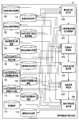
- FIG. 1 is a diagram illustrating an example of a configuration of an entire system including a microgrid and a commercial-side network to which an integrated monitoring control system according to an embodiment of the present invention is applied.
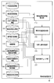
- FIG. 2 is a diagram showing an example of the configuration of the comprehensive monitoring control system shown in FIG.
- FIG. 3 is a diagram illustrating an example of the configuration of the measurement value monitoring unit 32.
- FIG. 4 is a diagram illustrating an example of the configuration of the customer information management unit 33.
- FIG. 5 is a diagram illustrating an example of the configuration of the demand load adjustment unit 25.
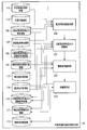
- FIG. 6 is a diagram illustrating an example of the configuration of the abnormal-time accommodation procedure creation unit 41.
- FIG. 7 is a diagram illustrating an example of the configuration of the pre-accident system restoration unit 42.
- FIG. 8 is a diagram illustrating an example of the configuration of the work plan-time accommodation procedure creation unit 39.
- FIG. 9 is a diagram illustrating an example of the configuration of the work implementation accommodation procedure creation unit 40.
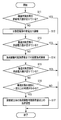
- FIG. 10 is a flowchart showing an example of the operation of the accident accommodation procedure creation unit 41 when an accident occurs.
- FIG. 11 is a system diagram of a microgrid in a case where it can be handled only by distributed power generation output adjustment.
- FIG. 12 is a system diagram of a microgrid in the case where it is possible to cope with distributed power generation output adjustment and one demand load adjustment.
- FIG. 13 is a system diagram of the microgrid in the case where it is possible to cope with the distributed power generation output adjustment and the two demand load adjustments.
- FIG. 1 is a diagram illustrating an example of a configuration of an entire system including a microgrid and a commercial-side network to which an integrated monitoring control system according to an embodiment of the present invention is applied. Note that the microgrid shown in FIG. 1 may be replaced with a smart grid.
- the microgrid 10 is connected to a commercial network C1 having a base power supply G101 and an adjustment power supply G102 at one connection point, and includes a plurality of distributed power supplies (including storage batteries) G1 to G6. And a demand facility (load) J1... Of a plurality of consumers, and a system capable of interconnection operation with the commercial network C1 and independent operation from the commercial network C1.
- Examples of distributed power sources include biomass generator G1, gas engine / gas turbine (GE / GT) generator G2, secondary battery G3, solar power generator G4, fuel cell G5, wind power generator G6 etc. are mentioned.
- the integrated supervisory control system 1 is a computer having various programs applicable not only to a microgrid but also to a smart grid.
- the power generation output of each distributed power source G1 to G6 in the microgrid 10 and each demand facility It is realized as a computer that monitors and controls each of the loads of J1.
- FIG. 2 is a diagram showing an example of the configuration of the comprehensive monitoring control system shown in FIG.
- 2 includes a frequency control unit 21, a supply and demand control unit 22, a system monitoring unit 23, a business support unit 24, a demand load adjustment unit 25, a supply and demand planning unit 26, SW ⁇ Voltage adjustment device state capturing unit 27, state grasping unit 28, power quality monitoring unit 29, facility management unit 30, drawing creation unit 31, measurement value monitoring unit 32, customer information management unit 33, accident section determination unit 34, work section setting Unit 35, accident processing unit 36, work planning unit 37, work execution unit 38, work plan interchange procedure creation unit 39, work implementation interchange procedure creation unit 40, abnormal accommodation procedure creation unit 41, pre-accident system recovery unit 42 Etc.
- the frequency control unit 21 controls the frequency of the power generation output of each distributed power source.
- the supply and demand control unit 22 controls supply and demand between each distributed power source and each demand facility.
- the system monitoring unit 23 monitors the system to which each distributed power source and each demand facility are connected.
- the business support unit 24 performs construction planning and construction business support.
- the demand load adjustment unit 25 adjusts the load amount of the corresponding demand facility in accordance with the accommodation procedure created by the abnormal time accommodation procedure creation unit 41 or the accommodation procedure created by the system recovery unit 42 before the accident. is there.
- the supply and demand planning unit 26 performs supply and demand planning for each distributed power source and each demand facility.
- the SW / voltage adjusting device state capturing unit 27 captures a signal indicating the state of the switch or voltage adjusting device.
- the state grasping unit 28 grasps whether or not an accident has occurred in the system.
- the power quality monitoring unit 29 monitors the power quality of the system.
- the facility management unit 30 performs system facility management.
- the drawing creation unit 31 creates a system drawing.
- the measurement value monitoring unit 32 acquires information indicating the current power generation output amount of each distributed power source and information indicating the current load amount of each demand facility, and records the past power generation output amount of each distributed power source.
- the information which shows and the information which shows the track record of the past load amount of each demand equipment is stored. For example, it is possible to perform a road survey with a measuring device such as a smart meter.
- the customer information management unit 33 manages contract items related to the customer's distributed power supply and demand facilities. For example, information indicating the rated power generation capacity and power generation output adjustable amount of each distributed power source, information indicating the contract power amount and load adjustable amount of each demand facility, and the distributed power source for adjusting the power generation output amount are determined. For example, information indicating the priority of each distributed power source and information indicating the priority of each demand facility for determining a demand facility for adjusting the load amount are managed.
- the accident section determination unit 34 determines a section where an accident has occurred in the system.
- the work section setting unit 35 sets a work section in the system.
- the accident processing unit 36 performs processing for accidents occurring in the system.
- the work planning unit 37 plans work in the system.
- the work execution unit 38 performs the planned work.
- the work plan adapting procedure creation unit 39 at least at the time of the work plan is information stored by the measurement value monitoring unit 32, information managed by the customer information management unit 33, and an environment corresponding to the power generation output amount of each distributed power source. Using the information indicating the degree of influence or the information indicating the cost according to the power generation output amount of each distributed power source, the interchange procedure of the system of the microgrid 10 that is assumed to be performed at the time of the work is created.
- the work implementation flexibility creation unit 40 uses at least the information acquired by the measurement value monitoring means and the information created at the time of work planning by the work planning flexibility procedure creation means at the time of work implementation.
- the abnormal-time accommodation procedure creation unit 41 uses each information obtained by at least the measurement value monitoring unit 32 and information managed by the customer information management unit 33.
- the interchange procedure which makes the highest priority to match the total power generation output amount of the type power supply with the total load amount of each demand facility is created.
- the pre-accident system restoration unit 42 restores the system to the state before the accident by using the information generated by the abnormality accommodation procedure creation unit 41 after an accident occurs.
- the interchange target section information 100 is information indicating a target section in which power interchange (including system operation) is performed.
- the system information 101 after accommodation is information indicating the configuration of the system after power accommodation, such as how much power is required in the section after system operation.
- the supply trouble section information 102 is information indicating a section where a supply trouble (power failure) occurs due to an accident.
- the in-system distributed power source information 103 is information indicating the rated capacity and the like of the distributed power source interconnected in the system.
- the contract demand power amount information 104 is information indicating the contract power amount of a customer linked in the system.
- the accident section recovery information 105 is information indicating the time required for recovery of the accident section.
- the distributed power generation output current information 106 is information indicating the current power generation output amount of the distributed power source interconnected in the system.
- Demand load current information 107 is information indicating a current demand load amount of a customer linked in the system.
- the distributed power generation output adjustment priority information 108 is information serving as a reference for determining an object to be adjusted when performing distributed power generation output adjustment. Made with reference to monetary incentives. For example, even if the same amount of power generation output is adjusted, the distributed power source A only costs 100,000 yen, while the distributed power source B costs 200,000 yen, the power output amount of the distributed power source A is adjusted.
- Demand load adjustment priority information 109 is information that serves as a reference for determining a target to be adjusted when performing demand load adjustment, like the distributed power generation output amount adjustment priority information 108.
- the distributed power generation output command information 110 is command information indicating how much the power generation output amount of the distributed power supply is adjusted. Based on this information, the frequency control unit 21 and the supply and demand control unit 22 actually control and adjust the distributed power source.
- Demand load adjustment command information 111 is command information indicating how much the load amount of the demand facility is adjusted. Based on this information, the demand load adjusting unit 25 actually adjusts the load amount of the demand facility.
- the facility information 112 is information on various facilities interconnected in the system.
- the switch state information 113 is information indicating the on / off state of the switches linked in the system.
- the work plan information 114 is information indicating the configuration of the system that is assumed as the work plan in the work plan. It includes the assumed distributed power generation output and demand load.
- the distributed power generation output result information 115 is information indicating a past result of the power generation output amount of the distributed power source interconnected in the system.
- the demand load record information 116 is information indicating a record of the trend of the demand load amount of the customer linked to the system so far.
- the environmental property calculation information 117 is information on environmental property such as how much power is generated by which kind of distributed power source and how much CO 2 is generated.
- the economic calculation information 118 is information on economics such as how much power is generated by what kind of distributed power source and how much it costs.
- the pre-work system information 119 is information indicating the structure of a healthy system before the work is performed.
- Demand load adjustment notification means information 120 is information indicating a contact method for making a request to a customer when requesting a load adjustment exceeding a limit amount that can be adjusted by the customer. For example, making a call, sending an email, ringing a bell, etc.
- the financial incentive calculation information 121 is information indicating a financial incentive determined by the type of contract with the customer. For example, it is information indicating that, although a normally high contract fee is paid, more financial incentives can be obtained than others when cooperating with demand load adjustment in an emergency.
- the post-accident system information 122 is information indicating the configuration of the system after the accident.
- the pre-accident system information 123 is information indicating a healthy system configuration before an accident occurs.
- CB on / off status information 124 is information indicating the on / off status of the circuit breakers linked in the system.
- FIG. 3 is a diagram illustrating an example of the configuration of the measurement value monitoring unit 32.
- the measurement value monitoring unit 32 includes a current value TM measurement unit 209 as a main function.
- the current value TM measurement unit 209 includes distributed power generation output current information 106 (information indicating the current power generation output amount of each distributed power source) and demand load current information 107 (information indicating the current load amount of each demand facility). Are stored in the storage medium, and the distributed power generation output result information 115 (information indicating the results of the distributed power generation output current information 106 acquired so far, for example) and the demand load result information 116 are acquired. (Information indicating the actual result such as the trend of the demand load current information 107 acquired so far) is created and stored in the storage medium.
- FIG. 4 is a diagram illustrating an example of the configuration of the customer information management unit 33.
- the customer information management unit 33 includes a customer information storage unit 211, a distributed power generation output adjustment priority information creation 212, and a demand load adjustment priority information creation unit 123 as main functions.
- the customer information storage unit 211 uses the demand load adjustment notification unit information 120 acquired in advance, the distributed power generation output current information 106 and the demand load current information 107 provided from the measurement value monitoring unit 32 to Distributed power source information 103 (information indicating the rated power generation capacity of each distributed power source, whether or not power generation output can be adjusted, the amount of power generation output adjustable), and contract demand power amount information 104 (contract power amount and load of each demand facility)
- Distributed power source information 103 information indicating the rated power generation capacity of each distributed power source, whether or not power generation output can be adjusted, the amount of power generation output adjustable
- contract demand power amount information 104 contract power amount and load of each demand facility
- monetary incentive calculation information 121 monetary incentives to be paid to customers when adjusting the power generation output amount of each distributed power source or the load amount of each demand facility Information
- the created in-system distributed power supply information 103 and contract demand power amount information 104 are provided to the abnormal-time accommodation procedure creation unit 41 as necessary.
- the distributed power generation output adjustment priority information creation unit 212 uses the distributed power supply information 103 in the system and the monetary incentive calculation information 121 stored by the customer information storage unit 211 to use the distributed power generation output adjustment priority information.
- 108 (information indicating the priority of each distributed power source for determining the distributed power source for adjusting the power generation output amount) is created and stored in a storage medium.
- the created distributed power generation output adjustment priority information 108 is provided to the abnormality-time accommodation procedure creation unit 41 and the work implementation-time accommodation procedure creation unit 40 as necessary.
- the demand load adjustment priority information creation unit 123 uses the contract demand power amount information 104 and the monetary incentive calculation information 121 stored by the customer information storage unit 211 to use the demand load adjustment priority information 109 (load amount adjustment). Information indicating the priority of each demand facility for determining the demand facility to perform) is created and stored in a storage medium.
- the created demand load adjustment priority information 109 is provided to the abnormality-time accommodation procedure creation unit 41 and the work implementation-time accommodation procedure creation unit 40 as necessary.
- the demand load adjustment priority information creation unit 123 also has a function of creating economic calculation information 118 (information indicating the cost according to the power generation output amount of each distributed power source) and storing it in a storage medium. Yes.
- the created economic calculation information 118 is provided to the work plan accommodation procedure creation section 39 and the work implementation accommodation procedure creation section 40 as necessary.
- FIG. 5 is a diagram illustrating an example of the configuration of the demand load adjustment unit 25.
- the demand load adjustment unit 25 includes a demand load adjustment execution unit 210 as a main function.
- the demand load adjustment execution unit 210 includes a demand load adjustment command information 111 provided from the system restoration unit 42 before the accident or the accommodation procedure creation unit 40 during work execution, and a demand load adjustment notification provided from the customer information storage unit 211 and the like. Using the means information 120, the load amount of any demand facility indicated in the command information is adjusted.
- FIG. 6 is a diagram illustrating an example of a configuration of the abnormal time accommodation procedure creation unit 41.
- the abnormal accommodation procedure creation unit 41 includes, as main functions, an after-conversion system determination unit 200, a distributed power generation output adjustment amount determination unit 201, a demand load adjustment amount determination unit 202, a supply failure section recovery unit 203, and a healthy power failure A section restoration unit 204 is provided.
- the post-accommodation system determination unit 200 uses the interchange target section information 100 provided from the system monitoring unit 23 and the like to determine the system after power accommodation and to restore the healthy power outage section at that time. By determining the amount, the system information 101 after accommodation is created and stored in a storage medium.
- the distributed power generation output adjustment amount determination unit 201 includes post-conversion system information 101 determined by the post-conversion system determination unit 200, distributed power generation output current information 106 provided from the measurement value monitoring unit 32, and customer information.
- Distributed power generation including a procedure for adjusting the power generation output amount of any of the distributed power sources using the distributed power source information 103 and the distributed power generation output adjustment priority information 108 provided from the management unit 33
- Output command information 110 is created and stored in a storage medium.
- the demand load adjustment amount determination unit 202 when the supply power amount is insufficient only by the power generation output adjustment by the distributed power generation output adjustment unit 201, the system information 101 after the interchange determined by the system determination unit 200 after the interchange, the measurement value Using the demand load current information 107 provided from the monitoring unit 32 and the contract demand power amount information 104 and the demand load adjustment priority information 109 provided from the customer information management unit 33, the load amount of any demand facility Demand load adjustment command information 111 including an accommodation procedure for adjusting the demand is created and stored in a storage medium.
- the supply trouble section restoration unit 203 is provided with the accident section provided from the accident processing unit 36 when the amount of supplied power is insufficient even after the load adjustment by the demand load adjustment unit 202 and it takes a certain amount of time to recover from the accident.
- the customer can further adjust the load amount of the demand facility (the load adjustment more than the load adjustment amount of the consumer main body). ) Is requested, and the demand load adjustment amount determination unit 202 ′ is instructed to create a further load adjustment accommodation procedure.
- the demand load adjustment amount determination unit 202 ′ is a system information 101 after interchange determined by the system determination unit 200 after interchange according to an instruction from the supply failure section restoration unit 203, and demand load current information provided from the measurement value monitoring unit 32. 107 and demand load adjustment including a procedure for further adjusting the load amount of any demand facility using contract demand power amount information 104 and demand load adjustment priority information 109 provided from the customer information management unit 33
- the command information 111 is created and stored in a storage medium.
- the demand load adjustment amount determination unit 202 ′ may be integrated with the demand load adjustment amount determination unit 202.
- the healthy power failure section restoration unit 204 gives priority to the distributed power generation output adjustment information provided from the distributed power generation output current information 106 and the current demand load information 107 provided from the measurement value monitoring unit 32 and the customer information management unit 33.
- Power supply including an accommodation procedure for performing recovery taking into account the reverse power flow of a distributed power supply provided in a demand facility that performs accommodation processing to a healthy power outage section using degree information 108 and demand load adjustment priority information 109
- Power generation output command information 110 and demand load adjustment command information 111 are created, and facility information 112 and switch state information 113 related to these are created and stored in a storage medium.
- the generated distributed power generation output command information 110, demand load adjustment command information 111, facility information 112, and switch state information 113 are frequency control unit 21, supply / demand control unit 22, demand load adjustment unit 25 as necessary. Or, it is provided to the system recovery unit 42 before the accident.
- FIG. 7 is a diagram showing an example of the configuration of the system restoration unit 42 before the accident.
- the pre-accident system restoration unit 42 includes an accident section accident cause removal section 214, an accident removal section power transmission section 215, a switchback operation execution section 216, and a system state check section 217 as main functions.
- the accident section accident cause removal unit 214 uses the accident section recovery information 105 and the post-accident system information 122 provided from the accident processing unit 36 to remove the cause of the accident in the accident section.
- the accident removal section power transmission unit 215 includes CB input / cutoff state information 124 provided from the system monitoring unit 23 and the like, and switch state information 113, facility information 112, distributed power supply provided from the abnormal accommodation procedure creation unit 41 Using the power generation output command information 110 and the demand load adjustment command information 111, power is transmitted to the section where the cause of the accident has been removed by the accident section accident cause removing unit 214.
- the switchback operation execution unit 216 uses the pre-accident system information 123, the CB input interruption state information 124, and the facility information 112 to adjust the power generation output of the split power source. Then, by adjusting the load of the demand facility, an operation procedure for returning the system to the power transmission form before the accident is created and the switchback operation is executed.
- the system state check unit 217 After the switchback operation is performed by the switchback operation execution unit 216, the system state check unit 217 performs the distributed power generation provided from the switch state information 113 and the facility information 112 and the measured value monitoring unit 32 described above. Using the current output information 106 and the current demand load information 107, the system status (overload, voltage status, etc.) is checked to confirm that there is no problem in power quality.
- FIG. 8 is a diagram illustrating an example of the configuration of the work plan accommodation procedure creation unit 39.
- the work plan accommodation procedure creation unit 39 includes, as main functions, an accommodation target section supply power amount determination unit 205, a distributed power generation output planning unit 206, and a demand load planning unit 207.
- the interchange target section supply power amount determination unit 205 includes the interchange target section information 100 provided from the system monitoring unit 23 and the like, and the distributed power generation output result information 115 and the demand load record information provided from the measurement value monitoring unit 32.
- a part of the work plan information 114 is created by determining the power supply amount of the section to be accommodated using 116 and stored in a storage medium.
- the distributed power generation output planning unit 206 uses the information determined by the interchange target section supply power amount determination unit 205, the distributed power generation output result information 115 provided from the measurement value monitoring unit 32, the customer information management unit 33 using the distributed power generation output adjustment priority information 108, environmental calculation information 117, and economic calculation information 118 provided from 33, the environmental impact level or each dispersion according to the power generation output amount of each distributed power source
- a part of the work plan information 114 is created and stored in a storage medium by planning the power generation output amount of each distributed power source while considering the cost according to the power generation output amount of the power source.
- the demand load planning unit 207 uses the information determined by the distributed power generation output planning unit 206, demand load actual information 116 provided from the measured value monitoring unit 32, and demand load provided from the customer information management unit 33. By using the adjustment priority information 109 and the economic efficiency calculation information 118, the load amount of each demand facility is planned while taking into account the cost according to the load amount of each demand facility. A part is created and stored in a storage medium.
- FIG. 9 is a diagram illustrating an example of the configuration of the work procedure accommodation procedure creation unit 40.
- the work execution accommodation procedure creation unit 40 includes, as main functions, an accommodation target system monitoring unit 208, a distributed power generation output adjustment unit 201, a demand load adjustment unit 202, and a healthy power outage section restoration unit 218.
- the interchangeable system monitoring unit 208 is provided from the pre-work system information 119 provided from the work plan unit 37 and the like, the work plan information 114 provided from the work plan interchange procedure creation unit 39, and the measurement value monitoring unit 32.
- the distributed power generation output current information 106 and the demand load current information 107 are used to recognize the difference between the system state at the time of performing the work and the system state assumed as at the time of performing the work at the time of work planning. .
- the distributed power generation output adjustment unit 201 uses the information recognized by the interchangeable system monitoring unit 208 and provides the distributed power generation output current information 106 provided from the measurement value monitoring unit 32 and the customer information management unit 33. Using the distributed power generation output adjustment priority information 108, the environmental calculation information 117, and the economic calculation information 118, the degree of environmental impact corresponding to the power generation output amount of each distributed power source or the power generation of each distributed power source.
- the distributed power generation output command information 110 including the accommodation procedure for adjusting the power generation output amount of any of the distributed power sources is created while taking into account the cost according to the output amount, and stored in a storage medium.
- the demand load adjustment unit 202 includes the current demand load information 107 provided from the measured value monitoring unit 32 and customer information management when the supply power amount is insufficient only by the power generation output adjustment by the distributed power generation output adjustment unit 201.
- the demand load adjustment priority information 109 and economic calculation information 118 provided from the unit 33 the accommodation for adjusting the load amount of any demand facility while taking into account the cost according to the load amount of each demand facility
- Demand load adjustment command information 111 including a procedure is created and stored in a storage medium.
- the healthy power outage section recovery unit 218 uses the pre-operation system information 119 provided from the operation plan unit 37 and the like to perform recovery in consideration of the reverse power flow of the distributed power source provided in the demand facility for performing the accommodation processing.
- An accommodation procedure is created, distributed power generation output command information 110 and demand load adjustment command information 111 reflecting the accommodation procedure are created, and switch state information 113 is created and stored in a storage medium. .
- the created distributed power generation output command information 110, demand load adjustment command information 111, and switch state information 113 are provided to the frequency control unit 21, the supply and demand control unit 22, or the demand load adjustment unit 25 as necessary.
- FIG. 10 is a flowchart showing an example of the operation of the accident accommodation procedure creation unit 41 when an accident occurs.
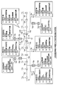
- FIG. 11 is a system diagram of a microgrid when it can be handled only by distributed power generation output adjustment
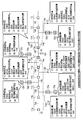
- FIG. 12 is a system diagram of a microgrid when it can be handled by distributed power generation output adjustment and one demand load adjustment
- FIG. 13 is a system diagram of the microgrid when it is possible to cope with the distributed power generation output adjustment and the demand load adjustment twice.
- the system shown in FIGS. 11 to 13 includes a CB (breaker) 10, a switch 11, a controllable distributed power source 12, a demand load 13, a section 14, a distribution line 15, an accident section, and a work section 16. Including.
- ranges 14a, 14b, 14c, 14d, 14e, 14g, 14h, and 14i surrounded by the dotted line represent the interchangeable sections
- range 14e surrounded by the alternate long and short dash line represents the portion that becomes the supply hindering section.
- the integrated monitoring control system 1 in FIG. 2 recognizes that the accident has occurred by the state grasping section 23, and determines the accident section by the accident section determination section 34.
- the accident processing unit 36 creates the accident section recovery information 105 in which the interchange target section information 100 and the time required for recovery of the accident location are registered.
- the comprehensive monitoring and control system 1 creates an accommodation procedure for accident recovery by the abnormality accommodation procedure creation unit 41 of FIG.
- the environment and economy are neglected because of the urgency, and the supply and demand match between each distributed power source and each demand facility, that is, the total power output of each distributed power source and the total load of each demand facility Create an interchange procedure for accident recovery where the highest priority is to match the volume.
- the system determination unit 200 after accommodation includes in-system interconnection distributed type including accommodation target section information 100, rated capacity of the distributed power source stored in the customer information storage unit 211, and the like. From the power supply information 103 and the current demand load information 107, the system information 101 after interchange and the supply trouble section information 102 are created. In response to this, the distributed power generation output adjustment unit 201 is generated by the distributed power generation output result information 115 created by the measurement value monitoring unit 32, the in-system interconnection distributed power supply information 103, and the customer information management unit 33. On the basis of the distributed power generation output adjustment priority information 108, an accommodation procedure for adjusting the power generation output amount of any of the distributed power sources so as to enable transmission to all demand loads in the system after the accommodation is created.
- FIG. 11 two interchangeable sections 14a, 14b, 14c, 14d, and 14e and interchangeable sections 14g, 14h, and 14i surrounded by dotted lines will be described.
- the total demand load of the interchangeable sections 14a, 14b, 14c, 14d, and 14e is 500 kW.
- the power generation output amount of the distributed power source is 400 kW.
- the section 14e surrounded by the chain line becomes a supply trouble section (No in step S11 in FIG. 10). Therefore, the power generation output of the controllable distributed power sources 12a and 12b is increased by 50 kW to prevent the supply trouble section from occurring (step S12).
- the priority when changing the output of the distributed power source is implemented based on the distributed power generation output adjustment priority information 108.
- the demand load adjustment unit 202 manages the system information 101 after the interchange and the customer information management unit 33.
- the contract demand power amount information 104 demand load adjustment priority information 109, and demand load current information 107 created by the measurement value monitoring unit 32, a financial incentive is made in a contract with a customer who is a customer in advance.
- step S14 an accommodation procedure for adjusting the load amount of the demand facility up to a load adjustable limit amount that allows the load amount of the demand facility to be adjusted within the determined range is created.
- step S15 If power supply to all the sections is impossible even after the adjustment by the distributed power generation output adjusting unit 201 and the demand load adjusting unit 202 (No in step S15), the supply trouble section restoring unit 203 has an accident.
- the section restoration information 105 and the supply trouble section information 102 are referred to.
- the demand load adjustment unit 202 ′ again performs the demand load adjustment priority information 109 in order to shorten the power failure time in the supply trouble section as much as possible.
- an interchange procedure for requesting the customer to make a load adjustment that is greater than the limit amount of the load adjustment by the customer with the financial incentive is created (step S17).
- the power generation output of the controllable distributed power sources 12a and 12b is increased by 50 kW, and the demand load amount of the demand load 13b is adjusted from the current demand load amount 250 kW. Even if 30 kW is adjusted up to the possible limit of 220 kW, there is not enough power, so the customer is requested to adjust the load more than the limit of the load-adjustable limit of the demanding entity with financial incentives. Generation of troubled sections can be prevented.
- Patent Document 11 and the like are helpful.
- the frequency control unit 21, the supply and demand control unit 22, and the demand load adjustment unit 25 are distributed power sources according to the distributed power generation output adjustment command information 110 and the demand load adjustment command information 111 created by the abnormal accommodation procedure creation unit 41. And control and adjustment of demand load.
- the demand load adjustment is performed after referring to the demand load adjustment notification means information 120 managed by the customer information management unit 33 and notifying the demand load adjustment by a notification method suitable for the consumer. In some cases, the load can be adjusted by remote operation without notifying the consumer.
- the healthy power failure section restoration unit 204 includes distributed power generation output adjustment command information 110, demand load adjustment command information 111, facility information 112, and switch state information 113, and is the reverse of the distributed power source provided in the demand facility. An interchange procedure to a healthy power outage section that takes into account the tidal current is created, and the accident processing unit 36 is notified of the result.
- the abnormal-time interchange procedure creation unit 41 enables creation of an accommodation procedure that minimizes the supply trouble as much as possible by enabling adjustment of the power generation output of the distributed power source and the load adjustment of the demand facility.
- the pre-accident system restoration unit 42 performs the switching operation and the system state check with the distributed power generation output adjustment and demand load adjustment in consideration of the environment and economy at the time of restoration to the pre-accident system after the accident removal. It becomes possible.
- the overall monitoring and control system 1 shown in FIG. 2 manages future planned work plans based on construction plan information managed by the facility management unit 30 when making work plans such as replacement of distribution lines and maintenance of distributed power sources. Is performed by the work planning unit 37. At the time of work, it is necessary to carry out an operation plan of a distributed power source that takes into consideration environmental factors and economic factors as in normal operation.
- the interchange target section supply power amount determination unit 205 is based on the interchange target section information 100 from the date and time when the work is scheduled to be performed.
- Ability and demand load are determined from the distributed power generation output record information 115 and demand load record information 116, and system information assumed at the time of performing the work is registered in the work plan information 114.
- the distributed power generation output planning unit 206 determines the demand load by the demand load planning unit 207 when there is a section that cannot be supplied even if a plan is made to maximize the generation output of the distributed power generation. Plan the adjustment and create a work execution system that does not cause supply disruption.
- the system monitoring unit 208 for accommodation creates work plan information 114 managed by the work plan unit 37 and the distributed power generation generated by the measurement value monitoring unit 32. Based on the current output information 106 and the current demand load information 107, by grasping the current system information, a difference from the state assumed at the time of work planning is recognized.
- the distributed power generation output adjustment unit 201 adjusts the power generation output amount of any of the distributed power sources according to the current demand load amount, and creates distributed power generation output adjustment command information 110 To do.
- the demand load adjustment unit 202 adjusts the load amount of the demand facility and creates an optimum accommodation procedure as the demand load adjustment command information 111.
- the power transmission operation unit 218 switches the system to perform the work, and notifies the work execution unit 38 of the result. At that time, based on the pre-work system information 119, a recovery operation procedure to the pre-work system that takes into account the reverse power flow of the distributed power source provided in the demand facility is also notified.
- the various functions described in the above embodiments are stored as computer programs in a computer-readable storage medium (for example, a magnetic disk, an optical disk, or a semiconductor memory), and read out by a processor as necessary. You may make it perform.
- a computer program can also be distributed by transmitting from one computer to another computer via a communication medium.
- the present invention is not limited to the above-described embodiment as it is, and can be embodied by modifying the constituent elements without departing from the scope of the invention in the implementation stage.
- various inventions can be formed by appropriately combining a plurality of components disclosed in the embodiment. For example, some components may be deleted from all the components shown in the embodiment.
- constituent elements over different embodiments may be appropriately combined.
Abstract
計測値モニタリング部(32)は、各分散型電源の現在の発電出力量を示す情報および各需要設備の現在の負荷量を示す情報を取得する。顧客情報管理部(33)は、少なくとも各分散型電源の定格発電容量および発電出力調整可能量を示す情報、各需要設備の契約電力量および負荷調整可能量を示す情報、ならびに発電出力量の調整を行う分散型電源を決定するための各分散型電源の優先度を示す情報および負荷量の調整を行う需要設備を決定するための各需要設備の優先度を示す情報を管理する。異常時融通手順作成部(41)は、系統に事故が発生した場合に、少なくとも計測値モニタリング部(32)により取得される情報および顧客情報管理部(33)により管理される情報を用いて、各分散型電源の総発電出力量と各需要設備の総負荷量とを一致させるための融通手順を作成する。
Description
本発明は、スマートグリッド及びマイクログリッド向け総合監視制御システムに関する。
我々が常日頃より使用する電力は、各種発電所(原子力、火力、水力など)で発電され、基幹系統・配電系統を経て高品質の電力が安定して需要家に供給されている。しかし、これまでの電力系統は、大量の電気の安定供給を目的として大規模集中型発電所を整備しているため、計画から運用開始までのリードタイムが長く、また、大規模発電所の立地条件を満足する地域は需要地から遠い場所が多いため熱回収率まで含めた総合エネルギー効率の向上に限界がある。
また、近年環境保護への意識の高まりや関連法の整備により、CO2削減など環境負荷低減の要求が高まっている。その対応策の一つとして、燃料電池、バイオマス発電、太陽光発電、風力発電、蓄電熱装置などの再生可能エネルギーの開発・実用化が急速に進みつつある。しかし、その一方では、太陽光、風力などの自然エネルギーを利用した分散型電源は、出力が不安定で制御が困難なため、今後、自然エネルギーを活用した多くの分散型電源が既存大規模電力網(以下、「商用側ネットワーク」と記す)と連系した場合、系統の安定性や信頼性といった電力品質に対し悪影響を及ぼす可能性があることが懸念されている。
これらの課題を解決する手段の一つとして、近年、スマートグリッドやマイクログリッドが世界各国で広く注目されている。例えばマイクログリッドは、需要地内に電源を置くことで高い総合エネルギー効率を得ることが可能である。また、自然変動電源など制御困難な電源と制御可能な電源とを組み合わせた電源構成とすることで、環境に配慮しつつ商用側ネットワークに影響を与えないネットワークとして構築することができる。それぞれの分散型電源の特徴を相互補完する形で、分散型電源を小規模ネットワーク化・システム化し、電力系統に対して影響をできる限り小さくし、また貢献することもできる「良き市民」となるのが「マイクログリッド」である。
マイクログリッドに関しては、我が国でも数多くの研究・実証試験が進められており、2003年度から2007年度までの計画で、愛知、京都、八戸などにおいてNEDからの委託による実証研究が行われている。マイクログリッドは環境問題の他にも、電力ピークカットや負荷平準化などの様々な施策の一つとして期待できる。マイクログリッドに関する報告は、平常運用時の円滑運用を意識した連系点潮流の同時同量に関する評価、または、分散型電源や電力貯蔵装置等を用いて如何に需給バランスをとるかといった需給制御機能に関する内容が多い(特許文献1~4)。
マイクログリッドの実運用を行うためには、商用側ネットワークと同等レベルの電力品質を維持した監視制御を行わなければならない。例えば、これまで自動給電システム(EMS: Energy Management System)が行っていた需給計画及び周波数制御など、配電自動化システム(DAS: Distribution Automation System)で行っていた充停電監視、系統操作、事故復旧及び電圧制御など(例えば特許5~11参照)、配電管理システム(DMS: Distribution Management System)で行っていた設備管理、工事の計画や建設の業務支援など、需要家エネルギー制御(DSM: Demand Side Management)で行っていた負荷制御(例えば特許文献12~13参照)などを全て行う必要がある。
現在の商用側ネットワーク(配電系統レベル)における電源容量は、夏季の需要ピーク時などを除けば、一箇所の電源端で1配電線全てを供給できるだけの電力量が保障されている。そのため、事故発生時や作業実施時に系統切替えを実施しても、他の電源元を確保しやすく、供給支障区間が発生する頻度が非常に少ない。しかし、マイクログリッドでは電力源が複数の小型分散型電源の集合群となるため、平常運用時では供給電力量が満たされた状態でも、系統切替えが行われると供給電力量が不足する区間が各所で発生する可能性が高い。そのため、電源容量が十分に確保されたことを前提にした従来の融通方式をマイクログリッドに適用しても、供給支障区間が多数発生することが想定される。
例えば、事故発生などの異常時には、緊急に供給予備力を確保するために、マイクログリッド内に連系された分散型電源の発電出力を変動させる必要がある。しかし、分散型電源の発電出力の調整を実施しても発電容量が小さいものや、太陽光発電、風力発電といった分散型電源のように発電出力を制御できないものが存在するため、十分供給電源量を確保できない場合がある。
また、作業計画時には、分散型電源の発電出力や需要負荷の調整計画を行って、作業実施系統を策定しなければならず、作業実施時には、平常運用時と同等の運用状態を維持しなければならない。しかし、マイクログリッド内にはその日の天候などにより発電出力量が変動する自然変動電源(風力発電、太陽光発電など)が存在するため、作業計画時に想定した系統状態と作業実施時の系統状態とが異なることが多い。
こうした課題は、マイクログリッドのみならず、スマートグリッドにおいても言えることである。
本発明は上記実情に鑑みてなされたものであり、スマートグリッドやマイクログリッドでの事故発生時もしくは作業実施時に電力を適切に融通させることが可能な総合監視制御システムを提供することを目的とする。
本発明の一態様による総合監視制御システムは、スマートグリッドもしくはマイクログリッドにおける個々の分散型電源の発電出力および需要設備の負荷の監視および制御を行う総合監視制御システムにおいて、各分散型電源の現在の発電出力量を示す情報および各需要設備の現在の負荷量を示す情報を取得する計測値モニタリング手段と、少なくとも各分散型電源の定格発電容量および発電出力調整可能量を示す情報、各需要設備の契約電力量および負荷調整可能量を示す情報、ならびに発電出力量の調整を行う分散型電源を決定するための各分散型電源の優先度を示す情報および負荷量の調整を行う需要設備を決定するための各需要設備の優先度を示す情報を管理する顧客情報管理手段と、前記マイクログリッドもしくはスマートグリッドの系統に事故が発生した場合に、少なくとも前記計測値モニタリング手段により取得される情報および前記顧客情報管理手段により管理される情報を用いて、各分散型電源の総発電出力量と各需要設備の総負荷量とを一致させるための融通手順を作成する異常時融通手順作成手段とを具備することを特徴とする。
本発明の他の態様による総合監視制御システムは、スマートグリッドもしくはマイクログリッドにおける個々の分散型電源の発電出力および需要設備の負荷の監視および制御を行う総合監視制御システムにおいて、各分散型電源の現在の発電出力量を示す情報および各需要設備の現在の負荷量を示す情報を取得するとともに、各分散型電源の過去の発電出力量の実績を示す情報および各需要設備の過去の負荷量の実績を示す情報を保管する計測値モニタリング手段と、少なくとも各分散型電源の定格発電容量および発電出力調整可能量を示す情報、各需要設備の契約電力量および負荷調整可能量を示す情報、ならびに発電出力量の調整を行う分散型電源を決定するための各分散型電源の優先度を示す情報および負荷量の調整を行う需要設備を決定するための各需要設備の優先度を示す情報を管理する顧客情報管理手段と、作業計画時に、少なくとも前記計測値モニタリング手段により保管される情報および前記顧客情報管理手段により管理される情報、ならびに各分散型電源の発電出力量に応じた環境影響度を示す情報もしくは各分散型電源の発電出力量に応じた費用を示す情報を用いて、作業実施時のものとして想定される前記スマートグリッドもしくはマイクログリッドの系統の融通手順を作成する作業計画時融通手順作成手段と、作業実施時に、少なくとも前記計測値モニタリング手段により取得される情報および前記作業計画時融通手順作成手段により作業計画時に作成された情報を用いて、当該作業実施時の系統状態と作業計画時に作業実施時のものとして想定された系統状態との差異を認識し、各分散型電源の総発電出力量と各需要設備の総負荷量とを一致させるための融通手順を作成する作業実施時融通手順作成手段とを具備することを特徴とする。
本発明によれば、スマートグリッドやマイクログリッドでの事故発生時もしくは作業実施時に電力を適切に融通させることが可能となる。
以下、図面を参照して、本発明の実施の形態について説明する。
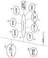
図1は、本発明の一実施形態に係る総合監視制御システムが適用されるマイクログリッドと商用側ネットワークとを含む全体システムの構成の一例を示す図である。なお、図1中に示されるマイクログリッドをスマートグリッドに代えた形態とすることも可能である。
図1に示されるように、マイクログリッド10は、ベース電源G101や調整用電源G102を有する商用側ネットワークC1と1つの連系点で接続され、複数の分散型電源(蓄電池を含む)G1~G6および複数の需要家の需要設備(負荷)J1…を有し、商用側ネットワークC1との連系運転及び商用側ネットワークC1からの独立運転が可能となるシステムである。
分散型電源(蓄電池を含む)の例としては、バイオマス発電機G1、ガスエンジン/ガスタービン(GE/GT)発電機G2、二次電池G3、太陽光発電機G4、燃料電池G5、風力発電機G6などが挙げられる。
総合監視制御システム1は、マイクログリッドのみならずスマートグリッドにも適用可能な各種のプログラムを備えたコンピュータであり、例えばマイクログリッド10における個々の分散型電源G1~G6の発電出力および個々の需要設備J1…の負荷のそれぞれの監視および制御を行うコンピュータとして実現される。
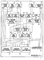
図2は、図1中に示される総合監視制御システムの構成の一例を示す図である。
図2に示される総合監視制御システム1は、各種の機能として、周波数制御部21、需給制御部22、系統監視部23、業務支援部24、需要負荷調整部25、需給計画部26、SW・電圧調整機器状態取り込み部27、状態把握部28、電力品質監視部29、設備管理部30、図面作成部31、計測値モニタリング部32、顧客情報管理部33、事故区間判定部34、作業区間設定部35、事故処理部36、作業計画部37、作業実施部38、作業計画時融通手順作成部39、作業実施時融通手順作成部40、異常時融通手順作成部41、事故前系統復旧部42などを備えている。
周波数制御部21は、各分散型電源の発電出力の周波数を制御するものである。
需給制御部22は、各分散型電源と各需要設備との需給の制御を行うものである。
系統監視部23は、各分散型電源および各需要設備が接続される系統を監視するものである。
業務支援部24は、工事の計画や建設の業務支援を行うものである。
需要負荷調整部25は、異常時融通手順作成部41により作成された融通手順、もしくは事故前系統復旧部42により作成された融通手順に従って、該当する需要設備の負荷量の調整を実施するものである。
需給計画部26は、各分散型電源と各需要設備との需給の計画を行うものである。
SW・電圧調整機器状態取り込み部27は、開閉器や電圧調整機器の状態を示す信号を取り込むものである。
状態把握部28は、系統内の事故の発生の有無などを把握するものである。
電力品質監視部29は、系統の電力品質を監視するものである。
設備管理部30は、系統の設備管理を行うものである。
図面作成部31は、系統の図面を作成するものである。
計測値モニタリング部32は、各分散型電源の現在の発電出力量を示す情報および各需要設備の現在の負荷量を示す情報を取得するとともに、各分散型電源の過去の発電出力量の実績を示す情報および各需要設備の過去の負荷量の実績を示す情報を保管するものである。例えば、スマートメータなどの計測機器によりロードサーベイの実施を行うことが可能である。
顧客情報管理部33は、顧客の分散型電源や需要設備に関する契約事項などを管理するものである。例えば、各分散型電源の定格発電容量および発電出力調整可能量を示す情報、各需要設備の契約電力量および負荷調整可能量を示す情報、ならびに発電出力量の調整を行う分散型電源を決定するための各分散型電源の優先度を示す情報および負荷量の調整を行う需要設備を決定するための各需要設備の優先度を示す情報などを管理している。
事故区間判定部34は、系統内の事故の発生した区間を判定するものである。
作業区間設定部35は、系統内の作業区間を設定するものである。
事故処理部36は、系統内で発生した事故に対する処理を行うものである。
作業計画部37は、系統内の作業を計画するものである。
作業実施部38は、計画した作業を実施するものである。
作業計画時融通手順作成部39は、作業計画時に、少なくとも計測値モニタリング部32により保管される情報および顧客情報管理部33により管理される情報、ならびに各分散型電源の発電出力量に応じた環境影響度を示す情報もしくは各分散型電源の発電出力量に応じた費用を示す情報を用いて、作業実施時のものとして想定されるマイクログリッド10の系統の融通手順を作成するものである。
作業実施時融通手順作成部40は、作業実施時に、少なくとも前記計測値モニタリング手段により取得される情報および前記作業計画時融通手順作成手段により作業計画時に作成された情報を用いて、当該作業実施時の系統状態と作業計画時に作業実施時のものとして想定された系統状態との差異を認識し、各分散型電源の総発電出力量と各需要設備の総負荷量とを一致させるための融通手順を作成するものである。
異常時融通手順作成部41は、マイクログリッド10の系統に事故が発生した場合に、少なくとも計測値モニタリング部32により取得される情報および顧客情報管理部33により管理される情報を用いて、各分散型電源の総発電出力量と各需要設備の総負荷量とを一致させることを最優先とする融通手順を作成するものである。
事故前系統復旧部42は、事故が発生した後に、異常時融通手順作成部41により生成された情報を用いて、系統を事故前の状態に復旧させるものである。
次に、図3~図9を参照して、図2の総合監視制御システム1に含まれる主要な要素の機能構成について説明する。
図3~図9においては、図示しない記憶媒体にそれぞれ記憶される各種の情報が存在する。図3~図9の機能構成を説明する前に、まず各種の情報について説明しておく。なお、共通する情報には、同一の符号を付している。
融通対象区間情報100は、電力融通(系統操作などを含む)を行う対象区間を示す情報である。
融通後系統情報101は、系統操作を行った後、その区間でどれだけの電力が必要となるかなどの電力融通後の系統の構成を示す情報である。
供給支障区間情報102は、事故により供給支障(停電)が発生する区間を示す情報である。
系統内分散型電源情報103は、系統内に連系されている分散型電源の定格容量などを示す情報である。
契約需要電力量情報104は、系統内に連系されている顧客の契約電力量を示す情報である。
事故区間復旧情報105は、事故区間の復旧に要する時間などを示す情報である。
分散型電源発電出力現在情報106は、系統内に連系されている分散型電源の現在の発電出力量を示す情報である。
需要負荷現在情報107は、系統内に連系されている顧客の現在の需要負荷量を示す情報である。
分散型電源発電出力調整優先度情報108は、分散型電源発電出力調整を行う際に、調整を行う対象を決める基準となる情報である。金銭的インセンティブ(報奨金)などを参考に作られる。例えば、同量の発電出力量の調整でも分散型電源Aでは10万円で済むのに対し、分散型電源Bでは20万円かかるなら分散型電源Aの発電出力量を調整するなど。
需要負荷調整優先度情報109は、分散型電源発電出力量調整優先度情報108と同様に、需要負荷調整を行う際に、調整を行う対象を決める基準となる情報である。
分散型電源発電出力指令情報110は、分散型電源の発電出力量をどれだけ調整するかを示す指令情報である。この情報に基づき、周波数制御部21及び需給制御部22が実際に分散型電源の制御及び調整を行う。
需要負荷調整指令情報111は、需要設備の負荷量をどれだけ調整するかを示す指令情報である。この情報に基づき、需要負荷調整部25が実際に需要設備の負荷量を調整する。
設備情報112は、系統内に連系されている各種設備の情報である。
開閉器状態情報113は、系統内に連系されている開閉器の入/切の状態を示す情報である。
作業計画情報114は、作業計画において作業実施時のものとして想定される系統の構成を示す情報である。想定される分散型電源発電出力量や需要負荷量も含む。
分散型電源発電出力実績情報115は、系統内に連系されている分散型電源のこれまでの発電出力量の傾向などの実績を示す情報である。
需要負荷実績情報116は、系統内に連系されている顧客のこれまでの需要負荷量の傾向などの実績を示す情報である。
環境性計算情報117は、どの種類の分散型電源でどれくらい発電するとそれに伴いどれくらいのCO2が発生するなどの環境性に関する情報である。
経済性計算情報118は、どの種類の分散型電源でどれくらい発電するとそれに伴いどれくらいの費用がかかるなどの経済性に関する情報である。
作業実施前系統情報119は、作業実施前の健全な系統の構成を示す情報である。
需要負荷調整通知手段情報120は、需要家主体の負荷調整可能限界量以上の負荷調整を依頼する際、顧客にその依頼をする連絡方法を示す情報である。例えば、電話をかける、メールを送る、ベルを鳴らすなど。
金銭的インセンティブ算出情報121は、顧客との契約の種類などにより決まる金銭的インセンティブを示す情報である。例えば、通常割高な契約料金を払っているが、緊急時に需要負荷調整に協力した際には、他人より多くの金銭的インセンティブをもらえることなどを示す情報である。
事故後系統情報122は、事故後の系統の構成を示す情報である。
事故前系統情報123は、事故が起こる前の健全な系統の構成を示す情報である。
CB投入遮断状態情報124は、系統内に連系している遮断機の投入/遮断の状態を示す情報である。
図3は、計測値モニタリング部32の構成の一例を示す図である。
計測値モニタリング部32は、主な機能として現在値TM計測部209を備えている。
現在値TM計測部209は、分散型電源発電出力現在情報106(各分散型電源の現在の発電出力量を示す情報)および需要負荷現在情報107(各需要設備の現在の負荷量を示す情報)を取得して、それらを記憶媒体に記憶するとともに、分散型電源発電出力実績情報115(これまで取得した分散型電源発電出力現在情報106の傾向などの実績を示す情報)および需要負荷実績情報116(これまで取得した需要負荷現在情報107の傾向などの実績を示す情報)を作成し、記憶媒体に記憶するものである。
図4は、顧客情報管理部33の構成の一例を示す図である。
顧客情報管理部33は、主な機能として、顧客情報保管部211、分散型電源発電出力調整優先度情報作成212、および需要負荷調整優先度情報作成部123を備えている。
顧客情報保管部211は、予め取得しておいた需要負荷調整通知手段情報120や、計測値モニタリング部32から提供される分散型電源発電出力現在情報106および需要負荷現在情報107を用いて、系統内分散型電源情報103(各分散型電源の定格発電容量、発電出力調整の可否、発電出力調整可能量などを示す情報)、ならびに契約需要電力量情報104(各需要設備の契約電力量、負荷調整の可否、負荷調整可能量などを示す情報)に加え、金銭的インセンティブ算出情報121(各分散型電源の発電出力量もしくは各需要設備の負荷量を調整する際に顧客へ支払う金銭的インセンティブを示す情報)を作成し、記憶媒体に保管するものである。作成した系統内分散型電源情報103や契約需要電力量情報104は、必要に応じて異常時融通手順作成部41へ提供される。
分散型電源発電出力調整優先度情報作成部212は、顧客情報保管部211により保管される系統内分散型電源情報103および金銭的インセンティブ算出情報121を用いて、分散型電源発電出力調整優先度情報108(発電出力量の調整を行う分散型電源を決定するための各分散型電源の優先度を示す情報)を作成し、記憶媒体に保管するものである。作成した分散型電源発電出力調整優先度情報108は、必要に応じて異常時融通手順作成部41や作業実施時融通手順作成部40へ提供される。
需要負荷調整優先度情報作成部123は、顧客情報保管部211により保管される契約需要電力量情報104および金銭的インセンティブ算出情報121を用いて、需要負荷調整優先度情報109(負荷量の調整を行う需要設備を決定するための各需要設備の優先度を示す情報)を作成し、記憶媒体に保管するものである。作成した需要負荷調整優先度情報109は、必要に応じて異常時融通手順作成部41や作業実施時融通手順作成部40へ提供される。また、この需要負荷調整優先度情報作成部123は、経済性計算情報118(各分散型電源の発電出力量に応じた費用などを示す情報)を作成し、記憶媒体に保管する機能も備えている。作成した経済性計算情報118は、必要に応じて作業計画時融通手順作成部39や作業実施時融通手順作成部40へ提供される。
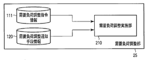
図5は、需要負荷調整部25の構成の一例を示す図である。
需要負荷調整部25は、主な機能として、需要負荷調整実施部210を備えている。
需要負荷調整実施部210は、事故前系統復旧部42もしくは作業実施時融通手順作成部40から提供される需要負荷調整指令情報111、および、顧客情報保管部211などから提供される需要負荷調整通知手段情報120を用いて、指令情報に示されるいずれかの需要設備の負荷量を調整するものである。
図6は、異常時融通手順作成部41の構成の一例を示す図である。
異常時融通手順作成部41は、主な機能として、融通後系統決定部200、分散型電源発電出力調整量決定部201、需要負荷調整量決定部202、供給支障区間復旧部203、および健全停電区間復旧部204を備えている。
融通後系統決定部200は、系統監視部23などから提供される融通対象区間情報100を用いて、電力融通後の系統を決定するとともにその際に健全停電区間を復旧するために必要となる電力量を決定することにより融通後系統情報101を作成し、記憶媒体に保管するものである。
分散型電源発電出力調整量決定部201は、融通後系統決定部200により決定された融通後系統情報101、計測値モニタリング部32から提供される分散型電源発電出力現在情報106、ならびに、顧客情報管理部33から提供される系統内分散型電源情報103および分散型電源発電出力調整優先度情報108を用いて、いずれかの分散型電源の発電出力量を調整する融通手順を含む分散型電源発電出力指令情報110を作成し、記憶媒体に保管するものである。
需要負荷調整量決定部202は、分散型電源発電出力調整部201による発電出力調整だけでは供給電力量が足りない場合に、融通後系統決定部200により決定された融通後系統情報101、計測値モニタリング部32から提供される需要負荷現在情報107、ならびに、顧客情報管理部33から提供される契約需要電力量情報104および需要負荷調整優先度情報109を用いて、いずれかの需要設備の負荷量を調整する融通手順を含む需要負荷調整指令情報111を作成し、記憶媒体に保管するものである。
供給支障区間復旧部203は、需要負荷調整部202による負荷調整によっても供給電力量が足りず、かつ、事故の復旧に一定以上の時間がかかる場合に、事故処理部36から提供される事故区間復旧情報105および計測値モニタリング部32から提供される分散型電源発電出力現在情報106を用いて、需要家に需要設備の更なる負荷量の調整(需要家主体の負荷調整可能量以上の負荷調整)の許諾を依頼する融通手順を作成し、需要負荷調整量決定部202’に対して更なる負荷調整の融通手順の作成を指示するものである。
需要負荷調整量決定部202’は、供給支障区間復旧部203の指示に応じ、融通後系統決定部200により決定された融通後系統情報101、計測値モニタリング部32から提供される需要負荷現在情報107、ならびに、顧客情報管理部33から提供される契約需要電力量情報104および需要負荷調整優先度情報109を用いて、いずれかの需要設備の負荷量を更に調整する融通手順を含む需要負荷調整指令情報111を作成し、記憶媒体に保管するものである。なお、この需要負荷調整量決定部202’は、需要負荷調整量決定部202と一体化されていても良い。
健全停電区間復旧部204は、計測値モニタリング部32から提供される分散型電源発電出力現在情報106および需要負荷現在情報107、ならびに、顧客情報管理部33から提供される分散型電源発電出力調整優先度情報108および需要負荷調整優先度情報109を用いて、健全停電区間への融通処理を実施する需要設備が備えている分散型電源の逆潮流を加味した復旧を行う融通手順を含む分散型電源発電出力指令情報110および需要負荷調整指令情報111を作成するとともに、これらに関連する設備情報112および開閉器状態情報113を作成し、記憶媒体に保管するものである。作成した分散型電源発電出力指令情報110、需要負荷調整指令情報111、設備情報112、および開閉器状態情報113は、必要に応じて、周波数制御部21、需給制御部22、需要負荷調整部25、もしくは事故前系統復旧部42へ提供される。
図7は、事故前系統復旧部42の構成の一例を示す図である。
事故前系統復旧部42は、主な機能として、事故区間事故原因除去部214、事故除去区間送電部215、切戻し操作実施部216、および系統状態チェック部217を備えている。
事故区間事故原因除去部214は、事故処理部36から提供される事故区間復旧情報105および事故後系統情報122を用いて、事故区間の事故原因の除去を行うものである。
事故除去区間送電部215は、系統監視部23などから提供されるCB投入遮断状態情報124、ならびに、異常時融通手順作成部41から提供される開閉器状態情報113、設備情報112、分散型電源発電出力指令情報110、および需要負荷調整指令情報111を用いて、事故区間事故原因除去部214により事故原因が除去された区間への送電を行うものである。
切戻し操作実施部216は、事故除去区間送電部215により送電が行われた後、事故前系統情報123、CB投入遮断状態情報124、および設備情報112を用いて、分割型電源の発電出力調整および需要設備の負荷調整により、系統を事故前の送電形態に戻す操作手順を作成して切戻し操作を実行するものである。
系統状態チェック部217は、切戻し操作実施部216により切戻し操作が行われた後、前述の開閉器状態情報113および設備情報112、ならびに、計測値モニタリング部32から提供される分散型電源発電出力現在情報106および需要負荷現在情報107を用いて、系統の状態(過負荷、電圧状態など)をチェックし、電力品質に問題が無いことを確認するものである。
図8は、作業計画時融通手順作成部39の構成の一例を示す図である。
作業計画時融通手順作成部39は、主な機能として、融通対象区間供給電力量決定部205、分散型電源発電出力計画部206、および需要負荷計画部207を備えている。
融通対象区間供給電力量決定部205は、系統監視部23などから提供される融通対象区間情報100、ならびに、計測値モニタリング部32から提供される分散型電源発電出力実績情報115および需要負荷実績情報116を用いて、融通対象区間の供給電力量を決定して作業計画情報114の一部を作成し、記憶媒体に保管するものである。
分散型電源発電出力計画部206は、融通対象区間供給電力量決定部205により決定された情報を用いるとともに、計測値モニタリング部32から提供される分散型電源発電出力実績情報115、顧客情報管理部33から提供される分散型電源発電出力調整優先度情報108、ならびに、環境性計算情報117および経済性計算情報118を用いて、各分散型電源の発電出力量に応じた環境影響度もしくは各分散型電源の発電出力量に応じた費用を加味しつつ、各分散型電源の発電出力量の計画を行うことにより、作業計画情報114の一部を作成し、記憶媒体に保管するものである。
需要負荷計画部207は、分散型電源発電出力計画部206により決定された情報を用いるとともに、計測値モニタリング部32から提供される需要負荷実績情報116、顧客情報管理部33から提供される需要負荷調整優先度情報109、および経済性計算情報118を用いて、各需要設備の負荷量に応じた費用を加味しつつ、各需要設備の負荷量の計画を行うことにより、作業計画情報114の一部を作成し、記憶媒体に保管するものである。
図9は、作業実施時融通手順作成部40の構成の一例を示す図である。
作業実施時融通手順作成部40は、主な機能として、融通対象系統監視部208、分散型電源発電出力調整部201、需要負荷調整部202、および健全停電区間復旧部218を備えている。
融通対象系統監視部208は、作業計画部37などから提供される作業実施前系統情報119、作業計画時融通手順作成部39から提供される作業計画情報114、ならびに、計測値モニタリング部32から提供される分散型電源発電出力現在情報106および需要負荷現在情報107を用いて、作業実施時の系統状態と作業計画時に作業実施時のものとして想定された系統状態との差異を認識するものである。
分散型電源発電出力調整部201は、融通対象系統監視部208により認識された情報を用いるとともに、計測値モニタリング部32から提供される分散型電源発電出力現在情報106、顧客情報管理部33から提供される分散型電源発電出力調整優先度情報108、ならびに、環境性計算情報117および経済性計算情報118用いて、各分散型電源の発電出力量に応じた環境影響度もしくは各分散型電源の発電出力量に応じた費用を加味しつつ、いずれかの分散型電源の発電出力量を調整する融通手順を含む分散型電源発電出力指令情報110を作成し、記憶媒体に保管するものである。
需要負荷調整部202は、分散型電源発電出力調整部201による発電出力調整だけでは供給電力量が足りない場合に、計測値モニタリング部32から提供される需要負荷現在情報107、ならびに、顧客情報管理部33から提供される需要負荷調整優先度情報109および経済性計算情報118を用いて、各需要設備の負荷量に応じた費用を加味しつつ、いずれかの需要設備の負荷量を調整する融通手順を含む需要負荷調整指令情報111を作成し、記憶媒体に保管するものである。
健全停電区間復旧部218は、作業計画部37などから提供される作業実施前系統情報119を用いて、融通処理を実施する需要設備が備えている分散型電源の逆潮流を加味した復旧を行う融通手順を作成し、当該融通手順を反映させた分散型電源発電出力指令情報110および需要負荷調整指令情報111を作成するとともに、開閉器状態情報113を作成し、記憶媒体に保管するものである。作成した分散型電源発電出力指令情報110、需要負荷調整指令情報111、および開閉器状態情報113は、必要に応じて、周波数制御部21、需給制御部22、もしくは需要負荷調整部25へ提供される。
次に、前述の図2および図6を参照しつつ、図10~図13を参照して、事故発生時の総合監視制御システム1の動作について説明する。
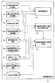
図10は、事故発生時の事故時融通手順作成部41の動作の一例を示すフローチャートである。図11は分散型電源発電出力調整のみで対応可能な場合のマイクログリッドの系統図、図12は分散型電源発電出力調整と1回の需要負荷調整で対応可能な場合のマイクログリッドの系統図、図13は分散型電源発電出力調整と2回の需要負荷調整で対応可能な場合のマイクログリッドの系統図である。なお、図11~図13に示される系統は、CB(遮断機)10、開閉器11、制御可能な分散型電源12、需要負荷13、区間14、配電線15、事故区間及び作業区間16を含む。また、点線で囲まれる範囲14a、14b、14c、14d、14e、14g、14h、14iは融通対象区間を表し、一点鎖線で囲まれる範囲14eは供給支障区間となってしまう箇所を表している。
図11のマイクログリッドにおいて、例えば区間14fで事故が発生した場合、図2の総合監視制御システム1は、状態把握部23により事故が発生したことを認識し、事故区間判定部34により事故区間を判定し、事故処理部36により融通対象区間情報100及び事故個所の復旧に要する時間などが登録される事故区間復旧情報105を作成する。
次に、総合監視制御システム1は、図6の異常時融通手順作成部41により事故復旧のための融通手順の作成を行う。異常時は、緊急を要すため環境性や経済性は度外視し、各分散型電源と各需要設備との需給の一致、即ち、各分散型電源の総発電出力量と各需要設備の総負荷量とを一致させることを最優先とする事故復旧のための融通手順を作成する。
図6の異常時融通手順作成部41においては、融通後系統決定部200は、融通対象区間情報100、顧客情報保管部211で保管する分散型電源の定格容量などを含む系統内連系分散型電源情報103及び需要負荷現在情報107から融通後系統情報101及び供給支障区間情報102を作成する。これを受け、分散型電源発電出力調整部201は、計測値モニタリング部32により作成される分散型電源発電出力実績情報115、系統内連系分散型電源情報103、顧客情報管理部33により作成される分散型電源発電出力調整優先度情報108に基づき、融通後系統において全ての需要負荷への送電が可能となるようにいずれかの分散型電源の発電出力量を調整する融通手順を作成する。
例えば、図11で示すように、点線で囲まれた2つの融通対象区間14a、14b、14c、14d、14eおよび融通対象区間14g、14h、14iについて説明する。融通対象区間14a、14b、14c、14d、14eの需要総負荷は500kWであり、一方、分散型電源の発電出力量は400kWであるため、需要負荷に対して発電出力が100kW分不足となり、一点鎖線で囲まれる区間14eが供給支障区間になってしまう(図10のステップS11のNo)。そこで、制御可能な分散型電源12a、12bの発電出力を50kWずつ増加させることにより、供給支障区間が発生しないようにしている(ステップS12)。分散型電源の出力を変更する際の優先順位は、分散型電源発電出力調整優先度情報108に基づき実施する。
分散型電源発電出力調整部201において、全ての需要負荷への電力供給が不可能な場合は(ステップS13のNo)、需要負荷調整部202が融通後系統情報101、顧客情報管理部33で管理する契約需要電力量情報104及び需要負荷調整優先度情報109、計測値モニタリング部32により作成される需要負荷現在情報107を参照することにより、予め顧客である需要家との契約で、金銭的インセンティブを支払う代わりに決められた範囲内で需要設備の負荷量を調整しても良いとする負荷調整可能限界量まで当該需要設備の負荷量を調整する融通手順を作成する(ステップS14)。
例えば、図12のような電力状況であった場合、制御可能な分散型電源12a、12bの発電出力を50kWずつ増加させても発電出力量が足りないため、需要負荷13bの需要負荷量を現在の需要負荷量250kWから負荷調整可能限界量200kWまで50kW分の需要負荷を削減することにより、供給支障区間が発生しないようにする。また、複数の需要設備の負荷調整が可能な場合には、金銭的インセンティブ算出情報121や契約需要電力量情報104などから、顧客情報管理部33で作成される需要負荷調整優先度情報109に基づき、どの負荷からどれだけの負荷調整を行うのか優先度を考慮して決定する。
分散型電源発電出力調整部201及び需要負荷調整部202による調整を実施しても全ての区間への電力供給が不可能な場合には(ステップS15のNo)、供給支障区間復旧部203が事故区間復旧情報105及び供給支障区間情報102を参照する。事故区間の復旧に時間がかかるようであれば(ステップS16のYes)、供給支障区間の停電時間を可能な限り短縮するために、再度需要負荷調整部202’によって、需要負荷調整優先度情報109などを参照し、需要家へ金銭的インセンティブを伴う需要家主体の負荷調整可能限界量以上の負荷調整を依頼する融通手順を作成する(ステップS17)。
例えば、図13のような電力状況であった場合、制御可能な分散型電源12a、12bの発電出力を50kWずつ増加させ、且つ需要負荷13bの需要負荷量を現在の需要負荷量250kWから負荷調整可能限界量220kWまで30kW調整しても電力が足りないため、需要家へ金銭的インセンティブを伴う需要化主体の負荷調整可能限界量以上の負荷調整を依頼し、20kWさらに負荷調整を行うことで供給支障区間の発生を防ぐことができる。分散型電源の予備力に関しては、特許文献11などが参考になる。
周波数制御部21、需給制御部22、及び需要負荷調整部25は、異常時融通手順作成部41で作成された分散型電源発電出力調整指令情報110及び需要負荷調整指令情報111に従い、分散型電源や需要負荷の制御及び調整を実施する。需要負荷調整の際には、顧客情報管理部33で管理する需要負荷調整通知手段情報120を参照し、需要家に適した通知方法で需要負荷調整を行うことを通知した後に実施する。尚、需要家には通知を行わずに遠隔操作により負荷調整できる場合もある。
また、健全停電区間復旧部204は、分散型電源発電出力調整指令情報110、需要負荷調整指令情報111、設備情報112及び開閉器状態情報113を含み、需要設備が備えている分散型電源の逆潮流も加味した健全停電区間への融通手順を作成し、その結果を事故処理部36へ通知する。
このように、マイクログリッド10内で事故が発生した場合、顧客情報管理部33で管理する情報や、計測値モニタリング部32で得た分散型電源発電出力情報や需要負荷情報などを参照することにより、異常時融通手順作成部41は分散型電源の発電出力調整及び需要設備の負荷調整を可能とすることによって、供給支障を可能な限り最小とするような融通手順を作成することが可能となる。また、事故前系統復旧部42によって、事故除去後の事故前系統への復旧時における環境性や経済性も加味した分散型電源発電出力調整や需要負荷調整を伴う切戻し操作及び系統状態チェックが可能となる。
次に、再び図2、図8および図9を参照して、作業計画時および作業実施時の総合監視制御システム1の動作について説明する。
図2の総合監視制御システム1は、配電線の張り替えや分散型電源のメンテナンス等の作業計画を立てる際、設備管理部30が管理する工事計画情報に基づき、今後予定される作業計画内容の管理を作業計画部37により行う。作業時には平常運用時と同様に環境性や経済性といったものも考慮した分散型電源の運転計画を行う必要がある。
図8の作業計画時融通手順作成部39においては、融通対象区間供給電力量決定部205が、融通対象区間情報100に基づき、作業実施が予定される日時より、想定される分散型電源発電出力量や需要負荷量を分散型電源発電出力実績情報115及び需要負荷実績情報116から判断し、作業実施時に想定される系統情報を作業計画情報114に登録する。
マイクログリッドの電力源は小型分散型電源の集合群となるため、平常時には需給バランスが取れていたにも関わらず、作業実施のための系統切替えにより十分な電力量を確保できなくなる可能性がある。このため、分散型電源発電出力計画部206は、分散型電源の発電出力を最大限運用とした計画を立てたとしても供給しきれない区間が生じる場合には、需要負荷計画部207による需要負荷調整を計画し、供給支障区間が生じることがないような作業実施系統を作成する。
需要負荷計画部207による需要負荷調整によっても、電力が足りないと想定される場合には、過渡的ではあるが、系統内に新たな分散型電源を投入することなどが考えられる。このような追加費用も考慮した上での、金銭的インセンティブの見直し等を含む需要負荷調整を再度考え、作業実施系統を見直す必要がある。
作業実施時には、図9の作業実施時融通手順作成部40において、融通対象系統監視部208が、作業計画部37で管理する作業計画情報114、計測値モニタリング部32により作成される分散型電源発電出力現在情報106及び需要負荷現在情報107に基づき、現在の系統情報を把握することで、作業計画時に想定した状態との差異を認識する。
差異がある場合には、分散型電源発電出力調整部201が、現在の需要負荷量に合わせていずれかの分散型電源の発電出力量を調整し、分散型電源発電出力調整指令情報110を作成する。
それでも電力が足りない時には、需要負荷調整部202が需要設備の負荷量を調整し、需要負荷調整指令情報111として最適な融通手順を作成する。
送電操作部218は、作業を実施するために系統を切替え、結果を作業実施部38へ通知する。その際、作業実施前系統情報119に基づき、需要設備が備えている分散型電源の逆潮流も加味した作業前系統への復旧操作手順も併せて通知する。
このように、マイクログリッド10内で作業の計画及び実施を行う場合においては、顧客情報管理部33で管理する情報や、計測値モニタリング部32で得た分散型電源発電出力情報や需要負荷情報などを参照することにより、環境性及び経済性を考慮した最適な作業系統を形成することが可能となる。
なお、上記実施形態で述べた各種の機能は、コンピュータプログラムとして、コンピュータにより読み取り可能な記憶媒体(例えば磁気ディスク,光ディスク,半導体メモリ)に記憶させておき、必要に応じてそれをプロセッサにより読み出して実行するようにしてもよい。また、このようなコンピュータプログラムは、通信媒体を介してあるコンピュータから他のコンピュータに伝送することにより配布することも可能である。
本発明は上記実施形態そのままに限定されるものではなく、実施段階ではその要旨を逸脱しない範囲で構成要素を変形して具体化できる。また、上記実施形態に開示されている複数の構成要素の適宜な組み合わせにより、種々の発明を形成できる。例えば、実施形態に示される全構成要素から幾つかの構成要素を削除してもよい。さらに、異なる実施形態にわたる構成要素を適宜組み合わせてもよい。
Claims (11)
- スマートグリッドもしくはマイクログリッドにおける個々の分散型電源の発電出力および需要設備の負荷の監視および制御を行う総合監視制御システムにおいて、
各分散型電源の現在の発電出力量を示す情報および各需要設備の現在の負荷量を示す情報を取得する計測値モニタリング手段(32)と、
少なくとも各分散型電源の定格発電容量および発電出力調整可能量を示す情報、各需要設備の契約電力量および負荷調整可能量を示す情報、ならびに発電出力量の調整を行う分散型電源を決定するための各分散型電源の優先度を示す情報および負荷量の調整を行う需要設備を決定するための各需要設備の優先度を示す情報を管理する顧客情報管理手段(33)と、
前記マイクログリッドもしくはスマートグリッドの系統に事故が発生した場合に、少なくとも前記計測値モニタリング手段(32)により取得される情報および前記顧客情報管理手段(33)により管理される情報を用いて、各分散型電源の総発電出力量と各需要設備の総負荷量とを一致させるための融通手順を作成する異常時融通手順作成手段(41)と
を具備することを特徴とする総合監視制御システム。 - 請求項1に記載の総合監視制御システムにおいて、
前記異常時融通手順作成手段(41)により生成された情報を用いて、前記マイクログリッドもしくはスマートグリッドの系統を事故前の状態に復旧させる事故前系統復旧手段(42)を更に具備することを特徴とする総合監視制御システム。 - 請求項1又は2に記載の総合監視制御システムにおいて、
前記異常時融通手順作成手段(41)は、
電力融通後の系統を決定するとともにその際に健全停電区間を復旧するために必要となる電力量を決定する融通後系統決定手段(200)と、
前記融通後系統決定手段(200)により決定された情報を用いて、いずれかの分散型電源の発電出力量を調整する融通手順を作成する分散型電源発電出力調整手段(201)と、
前記分散型電源発電出力調整による発電出力調整だけでは供給電力量が足りない場合に、いずれかの需要設備の負荷量を調整する融通手順を作成する需要負荷調整手段(202)と、
前記需要負荷調整手段(202)による負荷調整によっても供給電力量が足りず、かつ、事故の復旧に一定以上の時間がかかる場合に、需要家に需要設備の更なる負荷量の調整の許諾を依頼する融通手順を作成する供給支障区間復旧手段(203)と、
前記健全停電区間への融通処理を実施する需要設備が備えている分散型電源の逆潮流を加味した復旧を行う融通手順を作成する健全停電区間復旧手段(204)と
を有することを特徴とする総合監視制御システム。 - 請求項1乃至3のいずれか1項に記載の総合監視制御システムにおいて、
前記顧客情報管理手段(33)は、
各分散型電源の定格発電容量および発電出力調整可能量を示す情報、ならびに各需要設備の契約電力量および負荷調整可能量を示す情報に加え、各分散型電源の発電出力量もしくは各需要設備の負荷量を調整する際に顧客へ支払う金銭的インセンティブを示す情報を記憶媒体に保管する顧客情報保管手段(211)と、
前記顧客情報保管手段(211)により保管される情報を用いて、発電出力量の調整を行う分散型電源を決定するための各分散型電源の優先度を示す情報を作成して記憶媒体に保管する分散型電源発電出力調整優先度情報作成手段(212)と、
前記顧客情報保管手段(211)により保管される情報を用いて、負荷量の調整を行う需要設備を決定するための各需要設備の優先度を示す情報を作成して記憶媒体に保管する需要負荷調整優先度情報作成手段(213)と
を有することを特徴とする総合監視制御システム。 - 請求項1乃至4のいずれか1項に記載の総合監視制御システムにおいて、
前記異常時融通手順作成手段(41)により作成された融通手順に従って、該当する需要設備の負荷量の調整を実施する需要負荷調整手段(25)を更に具備することを特徴とする総合監視制御システム。 - 請求項2乃至5のいずれか1項に記載の総合監視制御システムにおいて、
前記事故前系統復旧手段(42)は、
事故区間の事故原因の除去を行う事故区間事故原因除去手段(214)と、
前記事故区間事故原因除去手段(214)により事故原因が除去された区間への送電を行う事故除去区間送電手段(215)と、
前記事故除去区間送電手段(215)により送電が行われた後、系統を事故前の送電形態に戻す操作手順を作成して切戻し操作を実行する切戻し操作実施手段(216)と、
前記切戻し操作実施手段(216)により切戻し操作が行われた後、系統の状態をチェックする系統状態チェック手段(217)と
を有することを特徴とする総合監視制御システム。 - スマートグリッドもしくはマイクログリッドにおける個々の分散型電源の発電出力および需要設備の負荷の監視および制御を行う総合監視制御システムにおいて、
各分散型電源の現在の発電出力量を示す情報および各需要設備の現在の負荷量を示す情報を取得するとともに、各分散型電源の過去の発電出力量の実績を示す情報および各需要設備の過去の負荷量の実績を示す情報を保管する計測値モニタリング手段(32)と、
少なくとも各分散型電源の定格発電容量および発電出力調整可能量を示す情報、各需要設備の契約電力量および負荷調整可能量を示す情報、ならびに発電出力量の調整を行う分散型電源を決定するための各分散型電源の優先度を示す情報および負荷量の調整を行う需要設備を決定するための各需要設備の優先度を示す情報を管理する顧客情報管理手段(33)と、
作業計画時に、少なくとも前記計測値モニタリング手段(32)により保管される情報および前記顧客情報管理手段(33)により管理される情報、ならびに各分散型電源の発電出力量に応じた環境影響度を示す情報もしくは各分散型電源の発電出力量に応じた費用を示す情報を用いて、作業実施時のものとして想定される前記スマートグリッドもしくはマイクログリッドの系統の融通手順を作成する作業計画時融通手順作成手段(39)と、
作業実施時に、少なくとも前記計測値モニタリング手段(32)により取得される情報および前記作業計画時融通手順作成手段(39)により作業計画時に作成された情報を用いて、当該作業実施時の系統状態と作業計画時に作業実施時のものとして想定された系統状態との差異を認識し、各分散型電源の総発電出力量と各需要設備の総負荷量とを一致させるための融通手順を作成する作業実施時融通手順作成手段(40)と
を具備することを特徴とする総合監視制御システム。 - 請求項7に記載の総合監視制御システムにおいて、
前記作業計画時融通手順作成手段(39)は、
前記計測値モニタリング手段(32)により保管される情報を用いて、融通対象区間の供給電力量を決定する融通対象区間供給電力量決定手段(205)と、
前記融通対象区間供給電力量決定手段(205)により決定された情報を用いて、各分散型電源の発電出力量に応じた環境影響度もしくは各分散型電源の発電出力量に応じた費用を加味しつつ、各分散型電源の発電出力量の計画を行う分散型電源発電出力計画手段(206)と、
前記分散型電源発電出力計画手段(206)により決定された情報を用いて、各需要設備の負荷量に応じた費用を加味しつつ、各需要設備の負荷量の計画を行う需要負荷計画手段(207)と
を有することを特徴とする総合監視制御システム。 - 請求項7に記載の総合監視制御システムにおいて、
前記作業実施時融通手順作成手段(40)は、
作業実施時の系統状態と作業計画時に作業実施時のものとして想定された系統状態との差異を認識する融通対象系統監視手段(208)と、
前記融通対象系統監視手段(208)により認識された情報を用いて、各分散型電源の発電出力量に応じた環境影響度もしくは各分散型電源の発電出力量に応じた費用を加味しつつ、いずれかの分散型電源の発電出力量を調整する融通手順を作成する分散型電源発電出力調整手段(201)と、
前記分散型電源発電出力調整手段(201)による発電出力調整だけでは供給電力量が足りない場合に、各需要設備の負荷量に応じた費用を加味しつつ、いずれかの需要設備の負荷量を調整する融通手順を作成する需要負荷調整手段(202)と、
融通処理を実施する需要設備が備えている分散型電源の逆潮流を加味した復旧を行う融通手順を作成する送電操作手段(218)と
を有することを特徴とする総合監視制御システム。 - スマートグリッドもしくはマイクログリッドにおける個々の分散型電源の発電出力および需要設備の負荷の監視および制御を行うコンピュータを、
各分散型電源の現在の発電出力量を示す情報および各需要設備の現在の負荷量を示す情報を取得する計測値モニタリング手段(32)、
少なくとも各分散型電源の定格発電容量および発電出力調整可能量を示す情報、各需要設備の契約電力量および負荷調整可能量を示す情報、ならびに発電出力量の調整を行う分散型電源を決定するための各分散型電源の優先度を示す情報および負荷量の調整を行う需要設備を決定するための各需要設備の優先度を示す情報を管理する顧客情報管理手段(33)、および、
前記マイクログリッドもしくはスマートグリッドの系統に事故が発生した場合に、少なくとも前記計測値モニタリング手段(32)により取得される情報および前記顧客情報管理手段(33)により管理される情報を用いて、各分散型電源の総発電出力量と各需要設備の総負荷量とを一致させるための融通手順を作成する異常時融通手順作成手段(41)
として機能させるためのプログラム。 - スマートグリッドもしくはマイクログリッドにおける個々の分散型電源の発電出力および需要設備の負荷の監視および制御を行うコンピュータを、
各分散型電源の現在の発電出力量を示す情報および各需要設備の現在の負荷量を示す情報を取得するとともに、各分散型電源の過去の発電出力量の実績を示す情報および各需要設備の過去の負荷量の実績を示す情報を保管する計測値モニタリング手段(32)、
少なくとも各分散型電源の定格発電容量および発電出力調整可能量を示す情報、各需要設備の契約電力量および負荷調整可能量を示す情報、ならびに発電出力量の調整を行う分散型電源を決定するための各分散型電源の優先度を示す情報および負荷量の調整を行う需要設備を決定するための各需要設備の優先度を示す情報を管理する顧客情報管理手段(33)、
作業計画時に、少なくとも前記計測値モニタリング手段(32)により保管される情報および前記顧客情報管理手段(33)により管理される情報、ならびに各分散型電源の発電出力量に応じた環境影響度を示す情報もしくは各分散型電源の発電出力量に応じた費用を示す情報を用いて、作業実施時のものとして想定される前記スマートグリッドもしくはマイクログリッドの系統の融通手順を作成する作業計画時融通手順作成手段(39)、および、
作業実施時に、少なくとも前記計測値モニタリング手段(32)により取得される情報および前記作業計画時融通手順作成手段(39)により作業計画時に作成された情報を用いて、当該作業実施時の系統状態と作業計画時に作業実施時のものとして想定された系統状態との差異を認識し、各分散型電源の総発電出力量と各需要設備の総負荷量とを一致させるための融通手順を作成する作業実施時融通手順作成手段(40)
として機能させるためのプログラム。
Priority Applications (4)
| Application Number | Priority Date | Filing Date | Title |
|---|---|---|---|
| EP09849248.1A EP2477307B1 (en) | 2009-09-08 | 2009-12-14 | Comprehensive monitoring and control system for smart grid and microgrid |
| CN200980160439.8A CN102474131B (zh) | 2009-09-08 | 2009-12-14 | 面向智能电网及微电网的综合监视控制系统 |
| IN1861DEN2012 IN2012DN01861A (ja) | 2009-09-08 | 2009-12-14 | |
| US13/405,605 US8774979B2 (en) | 2009-09-08 | 2012-02-27 | Executive monitoring and control system for smart grid and micro grid |
Applications Claiming Priority (2)
| Application Number | Priority Date | Filing Date | Title |
|---|---|---|---|
| JP2009-207238 | 2009-09-08 | ||
| JP2009207238A JP5618511B2 (ja) | 2009-09-08 | 2009-09-08 | スマートグリッド及びマイクログリッド向け総合監視制御システム |
Related Child Applications (1)
| Application Number | Title | Priority Date | Filing Date |
|---|---|---|---|
| US13/405,605 Continuation US8774979B2 (en) | 2009-09-08 | 2012-02-27 | Executive monitoring and control system for smart grid and micro grid |
Publications (1)
| Publication Number | Publication Date |
|---|---|
| WO2011030472A1 true WO2011030472A1 (ja) | 2011-03-17 |
Family
ID=43732156
Family Applications (1)
| Application Number | Title | Priority Date | Filing Date |
|---|---|---|---|
| PCT/JP2009/070840 WO2011030472A1 (ja) | 2009-09-08 | 2009-12-14 | スマートグリッド及びマイクログリッド向け総合監視制御システム |
Country Status (6)
| Country | Link |
|---|---|
| US (1) | US8774979B2 (ja) |
| EP (1) | EP2477307B1 (ja) |
| JP (1) | JP5618511B2 (ja) |
| CN (1) | CN102474131B (ja) |
| IN (1) | IN2012DN01861A (ja) |
| WO (1) | WO2011030472A1 (ja) |
Cited By (9)
| Publication number | Priority date | Publication date | Assignee | Title |
|---|---|---|---|---|
| CN102185332A (zh) * | 2011-05-10 | 2011-09-14 | 云南电力试验研究院(集团)有限公司 | 微网与大电网的交换功率控制方法 |
| CN102280935A (zh) * | 2011-06-24 | 2011-12-14 | 中国科学院电工研究所 | 一种智能电网管理系统 |
| CN102593833A (zh) * | 2012-03-19 | 2012-07-18 | 上海电力学院 | 一种独立微网频率控制器设计方法 |
| JP2012235644A (ja) * | 2011-05-06 | 2012-11-29 | Ntt Data Corp | 電力シミュレーション装置、電力シミュレーション方法、電力シミュレーションプログラム |
| CN103311958A (zh) * | 2012-03-14 | 2013-09-18 | 株式会社东芝 | 电力供需控制装置 |
| EP2662945A1 (en) * | 2012-05-08 | 2013-11-13 | VPP Energy Zrt. | Distributed power generation system, controlling means and method for controlling the power generation of the system |
| CN103562063A (zh) * | 2011-10-21 | 2014-02-05 | 三井造船株式会社 | 船舶 |
| CN103580291A (zh) * | 2013-11-27 | 2014-02-12 | 上海空间电源研究所 | 兼顾能量型功率型的电池储能系统及其控制方法 |
| EP2549617A3 (en) * | 2011-07-22 | 2015-05-27 | Kabushiki Kaisha Toshiba | Electrical quantity adjusting apparatus, electrical quantity adjusting method, electrical quantity adjusting program and power supply system |
Families Citing this family (35)
| Publication number | Priority date | Publication date | Assignee | Title |
|---|---|---|---|---|
| JP5755729B2 (ja) * | 2011-04-26 | 2015-07-29 | 株式会社日立製作所 | 電力管理装置、電力管理システム、電力管理方法、および電力管理プログラム |
| EP2953086A1 (en) | 2011-06-14 | 2015-12-09 | Kabushiki Kaisha Toshiba | Information integration control system, and information processing program, social infrastructure operation system, operation method, local apparatus, server apparatus, and program |
| WO2013082698A1 (en) | 2011-12-05 | 2013-06-13 | Hatch Ltd. | System, method and controller for managing and controlling a micro-grid |
| EP2814687B1 (en) * | 2012-02-13 | 2019-04-10 | Accenture Global Services Limited | Electric vehicle distributed intelligence |
| US10090704B2 (en) | 2012-02-21 | 2018-10-02 | Hitachi, Ltd. | Display device and display method of electric power system information |
| US10193339B2 (en) | 2012-07-30 | 2019-01-29 | Nec Corporation | Grid integrated control apparatus, grid control system, grid control apparatus, program, and control method |
| KR101344364B1 (ko) * | 2012-08-22 | 2013-12-24 | 한국에너지기술연구원 | 전력 수급 관리 장치 및 방법 |
| EP2713463B1 (de) * | 2012-09-28 | 2018-06-13 | Enrichment Technology Company Ltd. | Energiespeichersystem |
| WO2014058178A1 (ko) * | 2012-10-12 | 2014-04-17 | 한국전자통신연구원 | 스마트 그리드 시스템의 재구성을 지원하기 위한 블랙박스 장치 및 방법 |
| KR101428769B1 (ko) | 2012-10-12 | 2014-08-08 | 한국전자통신연구원 | 스마트 그리드 시스템의 재구성을 지원하기 위한 블랙박스 장치 및 방법 |
| CN103023035B (zh) * | 2012-11-26 | 2015-01-28 | 华北水利水电大学 | 一种多能互补发电系统的优化配置方法 |
| EP2904679B1 (de) * | 2012-12-11 | 2018-05-16 | Siemens Aktiengesellschaft | Verfahren zur steuerung des betriebs von elektrischen energieerzeugern und steuereinrichtung zur durchführung des verfahrens |
| EP2959561A4 (en) * | 2013-02-19 | 2016-09-14 | Solantro Semiconductor Corp | SELF-DIAGRAMS |
| US9935459B2 (en) | 2013-05-17 | 2018-04-03 | Nec Corporation | Power network system, and power adjustment apparatus and method |
| WO2014185036A1 (ja) * | 2013-05-17 | 2014-11-20 | 日本電気株式会社 | 電力ネットワークシステム並びに電力調整装置及び方法 |
| JP6080686B2 (ja) * | 2013-05-22 | 2017-02-15 | 株式会社日立製作所 | 需要調整システム、需要調整装置、および消費機器管理装置 |
| US10095256B2 (en) * | 2013-06-24 | 2018-10-09 | Nec Corporation | Power control device, method, and program based on evaluation functions regarding upper limit amount of power |
| GB2519755A (en) * | 2013-10-29 | 2015-05-06 | Bae Systems Plc | Controlling power distribution with a microgrid |
| US9625928B2 (en) * | 2014-02-24 | 2017-04-18 | General Electric Company | Systems and methods for error monitoring and handling in control systems |
| CN103986188B (zh) * | 2014-05-15 | 2016-05-04 | 国电南瑞科技股份有限公司 | 一种基于三元式的微电网模式智能识别方法 |
| JP6183754B2 (ja) * | 2014-05-21 | 2017-08-23 | パナソニックIpマネジメント株式会社 | 監視装置、およびそれを用いた監視システム |
| CN106462906B (zh) * | 2014-06-24 | 2019-08-13 | 三菱电机株式会社 | 能源管理系统以及电力流通方法 |
| US9742193B2 (en) | 2014-06-30 | 2017-08-22 | Mahindra EPC Services Pvt. Ltd. | System which intelligently and optimally controls power utilization from hybrid energy sources |
| JP6356517B2 (ja) * | 2014-07-23 | 2018-07-11 | 株式会社日立製作所 | 系統監視制御装置 |
| KR101936864B1 (ko) | 2014-10-06 | 2019-01-11 | 전자부품연구원 | 프로파일에 기반한 에너지저장시스템의 운영 방법 |
| CN105990852A (zh) * | 2015-02-16 | 2016-10-05 | 徐振斌 | 一种集成分布式发电储能连续输供电装置 |
| WO2016131161A1 (zh) * | 2015-02-16 | 2016-08-25 | 徐振斌 | 一种集成分布式发电储能连续输供电装置 |
| CN105703475B (zh) * | 2016-02-25 | 2019-01-25 | 广州广电运通金融电子股份有限公司 | 一种atm设备不间断智能供电方法和系统 |
| CN106208087B (zh) * | 2016-08-02 | 2019-05-21 | 南京南瑞继保电气有限公司 | 一种工业企业自发电功率平衡控制方法 |
| CN106230023B (zh) * | 2016-08-22 | 2018-09-28 | 中国石油化工股份有限公司洛阳分公司 | 一种企业自备电厂上下网功率自动调控方法 |
| US20180191160A1 (en) * | 2016-12-31 | 2018-07-05 | Abb Schweiz Ag | Small grid load control |
| TWI650917B (zh) * | 2018-01-22 | 2019-02-11 | 行政院原子能委員會核能研究所 | 可隨插即用之救災型再生能源微電網 |
| JP2022099683A (ja) * | 2020-12-23 | 2022-07-05 | トヨタ自動車株式会社 | 電力システムおよびサーバ |
| JP2024506166A (ja) * | 2021-02-09 | 2024-02-09 | ジョージア テック リサーチ コーポレイション | グリッド接続されたコンバータのための一元制御ストラテジ |
| CN113036809A (zh) * | 2021-04-21 | 2021-06-25 | 国网山东省电力公司枣庄供电公司 | 一种基于风光储一体化的新型农村配电网 |
Citations (15)
| Publication number | Priority date | Publication date | Assignee | Title |
|---|---|---|---|---|
| JPH0334292B2 (ja) | 1982-03-31 | 1991-05-22 | Tokyo Denryoku Kk | |
| JPH11313441A (ja) | 1998-04-27 | 1999-11-09 | Toshiba Corp | 家庭内電力dsmシステム |
| JP2000078748A (ja) | 1998-09-02 | 2000-03-14 | Mitsubishi Electric Corp | 電力dsmシステム |
| JP2005117787A (ja) | 2003-10-08 | 2005-04-28 | Hitachi Ltd | 配電系統負荷融通方法及び装置 |
| JP2006060885A (ja) | 2004-08-18 | 2006-03-02 | Mitsubishi Electric Corp | 配電系統監視制御方式 |
| JP2006094611A (ja) | 2004-09-22 | 2006-04-06 | Kansai Electric Power Co Inc:The | 配電系統事故復旧方法及び配電系統事故復旧装置 |
| JP2006246683A (ja) | 2005-03-07 | 2006-09-14 | Toshiba Corp | 配電線自動制御方法およびプログラム、ならびにそれを搭載した配電線自動制御システム |
| JP2007028769A (ja) | 2005-07-14 | 2007-02-01 | Chugoku Electric Power Co Inc:The | 配電線系統の事故復旧方法、配電制御装置 |
| JP2007323942A (ja) | 2006-05-31 | 2007-12-13 | Mitsumi Electric Co Ltd | スライドスイッチ |
| JP2008061382A (ja) | 2006-08-31 | 2008-03-13 | Toshiba Corp | マイクログリットの電力需給調整システム |
| JP2008136677A (ja) | 2006-12-01 | 2008-06-19 | Toshiba Corp | 電気掃除機 |
| JP2008201016A (ja) | 2007-02-21 | 2008-09-04 | Nissei Plastics Ind Co | 射出成形方法 |
| JP2008271723A (ja) | 2007-04-23 | 2008-11-06 | Toshiba Corp | 電力需給制御装置およびその方法 |
| JP2008301641A (ja) * | 2007-06-01 | 2008-12-11 | Meidensha Corp | 分散型電源の制御システムおよび制御方法 |
| JP2009148098A (ja) * | 2007-12-14 | 2009-07-02 | Toshiba Corp | 配電線自動制御システム、並びに配電線自動制御方法およびプログラム |
Family Cites Families (6)
| Publication number | Priority date | Publication date | Assignee | Title |
|---|---|---|---|---|
| JPH0334292A (ja) | 1989-06-29 | 1991-02-14 | Komatsu Ltd | 薄膜el素子を用いたドットマトリクスディスプレイ |
| JP2008042961A (ja) * | 2006-08-01 | 2008-02-21 | Toshiba Corp | 電力系統負荷周波数制御システム |
| JP4834515B2 (ja) * | 2006-11-06 | 2011-12-14 | 株式会社東芝 | 配電系統最適運用システムと方法、およびプログラム |
| CN101911421B (zh) * | 2007-12-12 | 2015-05-06 | Abb研究有限公司 | 恢复配电网中的电力的方法 |
| JP2009284723A (ja) | 2008-05-26 | 2009-12-03 | Toshiba Corp | 電力需給制御装置および電力需給制御方法 |
| JP5011230B2 (ja) | 2008-08-04 | 2012-08-29 | 株式会社東芝 | 二次電池の制御装置および制御方法 |
-
2009
- 2009-09-08 JP JP2009207238A patent/JP5618511B2/ja active Active
- 2009-12-14 IN IN1861DEN2012 patent/IN2012DN01861A/en unknown
- 2009-12-14 EP EP09849248.1A patent/EP2477307B1/en active Active
- 2009-12-14 WO PCT/JP2009/070840 patent/WO2011030472A1/ja active Application Filing
- 2009-12-14 CN CN200980160439.8A patent/CN102474131B/zh active Active
-
2012
- 2012-02-27 US US13/405,605 patent/US8774979B2/en active Active
Patent Citations (15)
| Publication number | Priority date | Publication date | Assignee | Title |
|---|---|---|---|---|
| JPH0334292B2 (ja) | 1982-03-31 | 1991-05-22 | Tokyo Denryoku Kk | |
| JPH11313441A (ja) | 1998-04-27 | 1999-11-09 | Toshiba Corp | 家庭内電力dsmシステム |
| JP2000078748A (ja) | 1998-09-02 | 2000-03-14 | Mitsubishi Electric Corp | 電力dsmシステム |
| JP2005117787A (ja) | 2003-10-08 | 2005-04-28 | Hitachi Ltd | 配電系統負荷融通方法及び装置 |
| JP2006060885A (ja) | 2004-08-18 | 2006-03-02 | Mitsubishi Electric Corp | 配電系統監視制御方式 |
| JP2006094611A (ja) | 2004-09-22 | 2006-04-06 | Kansai Electric Power Co Inc:The | 配電系統事故復旧方法及び配電系統事故復旧装置 |
| JP2006246683A (ja) | 2005-03-07 | 2006-09-14 | Toshiba Corp | 配電線自動制御方法およびプログラム、ならびにそれを搭載した配電線自動制御システム |
| JP2007028769A (ja) | 2005-07-14 | 2007-02-01 | Chugoku Electric Power Co Inc:The | 配電線系統の事故復旧方法、配電制御装置 |
| JP2007323942A (ja) | 2006-05-31 | 2007-12-13 | Mitsumi Electric Co Ltd | スライドスイッチ |
| JP2008061382A (ja) | 2006-08-31 | 2008-03-13 | Toshiba Corp | マイクログリットの電力需給調整システム |
| JP2008136677A (ja) | 2006-12-01 | 2008-06-19 | Toshiba Corp | 電気掃除機 |
| JP2008201016A (ja) | 2007-02-21 | 2008-09-04 | Nissei Plastics Ind Co | 射出成形方法 |
| JP2008271723A (ja) | 2007-04-23 | 2008-11-06 | Toshiba Corp | 電力需給制御装置およびその方法 |
| JP2008301641A (ja) * | 2007-06-01 | 2008-12-11 | Meidensha Corp | 分散型電源の制御システムおよび制御方法 |
| JP2009148098A (ja) * | 2007-12-14 | 2009-07-02 | Toshiba Corp | 配電線自動制御システム、並びに配電線自動制御方法およびプログラム |
Non-Patent Citations (1)
| Title |
|---|
| See also references of EP2477307A4 |
Cited By (14)
| Publication number | Priority date | Publication date | Assignee | Title |
|---|---|---|---|---|
| JP2012235644A (ja) * | 2011-05-06 | 2012-11-29 | Ntt Data Corp | 電力シミュレーション装置、電力シミュレーション方法、電力シミュレーションプログラム |
| CN102185332A (zh) * | 2011-05-10 | 2011-09-14 | 云南电力试验研究院(集团)有限公司 | 微网与大电网的交换功率控制方法 |
| CN102280935A (zh) * | 2011-06-24 | 2011-12-14 | 中国科学院电工研究所 | 一种智能电网管理系统 |
| US9257849B2 (en) | 2011-07-22 | 2016-02-09 | Kabushiki Kaisha Toshiba | Electrical quantity adjusting apparatus, electrical quantity adjusting method, electrical quantity adjusting program and power supply system |
| EP2549617A3 (en) * | 2011-07-22 | 2015-05-27 | Kabushiki Kaisha Toshiba | Electrical quantity adjusting apparatus, electrical quantity adjusting method, electrical quantity adjusting program and power supply system |
| US8736100B2 (en) | 2011-10-21 | 2014-05-27 | Mitsui Engineering & Ship Building Co., Ltd. | Ship |
| CN103562063A (zh) * | 2011-10-21 | 2014-02-05 | 三井造船株式会社 | 船舶 |
| CN103562063B (zh) * | 2011-10-21 | 2015-04-29 | 三井造船株式会社 | 船舶 |
| CN103311958A (zh) * | 2012-03-14 | 2013-09-18 | 株式会社东芝 | 电力供需控制装置 |
| CN102593833A (zh) * | 2012-03-19 | 2012-07-18 | 上海电力学院 | 一种独立微网频率控制器设计方法 |
| WO2013167921A1 (en) * | 2012-05-08 | 2013-11-14 | Vpp Energy Zrt. | Distributed power generation system, control means and method for controlling the power generation of the system |
| EP2662945A1 (en) * | 2012-05-08 | 2013-11-13 | VPP Energy Zrt. | Distributed power generation system, controlling means and method for controlling the power generation of the system |
| CN103580291A (zh) * | 2013-11-27 | 2014-02-12 | 上海空间电源研究所 | 兼顾能量型功率型的电池储能系统及其控制方法 |
| CN103580291B (zh) * | 2013-11-27 | 2015-09-30 | 上海空间电源研究所 | 兼顾能量型功率型的电池储能系统及其控制方法 |
Also Published As
| Publication number | Publication date |
|---|---|
| US8774979B2 (en) | 2014-07-08 |
| EP2477307A8 (en) | 2012-09-19 |
| IN2012DN01861A (ja) | 2015-08-21 |
| EP2477307A1 (en) | 2012-07-18 |
| JP5618511B2 (ja) | 2014-11-05 |
| US20120158202A1 (en) | 2012-06-21 |
| CN102474131A (zh) | 2012-05-23 |
| JP2011061931A (ja) | 2011-03-24 |
| CN102474131B (zh) | 2014-05-28 |
| EP2477307B1 (en) | 2015-09-16 |
| EP2477307A4 (en) | 2015-01-21 |
Similar Documents
| Publication | Publication Date | Title |
|---|---|---|
| JP5618511B2 (ja) | スマートグリッド及びマイクログリッド向け総合監視制御システム | |
| Chen et al. | Multi-time step service restoration for advanced distribution systems and microgrids | |
| Krishnamurthy et al. | Effects of power electronics, energy storage, power distribution architecture, and lifeline dependencies on microgrid resiliency during extreme events | |
| Venkateswaran et al. | Approaches for optimal planning of energy storage units in distribution network and their impacts on system resiliency | |
| Eckroad et al. | EPRI-DOE handbook of energy storage for transmission & distribution applications | |
| Kroposki et al. | Microgrid standards and technologies | |
| Kwasinski et al. | Microgrids and other local area power and energy systems | |
| Yang et al. | A criterion and stochastic unit commitment towards frequency resilience of power systems | |
| Prakash et al. | A review of battery energy storage systems for ancillary services in distribution grids: Current status, challenges and future directions | |
| Ma et al. | Fuel cell backup power system for grid-service and micro-grid in telecommunication applications | |
| Choobineh et al. | Emergency electric service restoration in the aftermath of a natural disaster | |
| Sadeghi Sarcheshmeh et al. | A stochastic frequency security constrained optimization model for day‐ahead energy and reserve scheduling of islanded multi‐microgrids systems | |
| Sheaffer et al. | Interconnection of Distributed Generation to Utility Systems | |
| Hartmann et al. | Island mode operation in intelligent microgrid—Extensive analysis of a case study | |
| Kirkham et al. | Energy management system design with dispersed storage and generation | |
| Corbus et al. | Oahu wind integration and transmission study: Summary report | |
| Nedd et al. | Security of Scottish electricity supply: gauging the perceptions of industry stakeholders | |
| Boyer | Identification and ranking of critical assets within an electrical grid under threat of cyber attack | |
| JP2022173702A (ja) | 電力系統制御システム、電力系統制御システムの制御方法及びプログラム | |
| Enyew | Study The Impact Of Distributed Generation On The Reliability Of Local Distribution System (Case Study: Motta Distribution Substation) | |
| SOLAK | ANKARA YILDIRIM BEYAZIT UNIVERSITY GRADUATE SCHOOL OF NATURAL AND APPLIED SCIENCES | |
| Hamidi | Reliability assessment of offshore networks for connection of offshore windfarms | |
| Hirose et al. | Smart Power Supply Systems for Mission Critical Facilities | |
| Gautam | Reliability studies of distribution systems integrated with energy storage | |
| Wang et al. | Analysis of renewable energy consumption and economy considering the joint optimal allocation of “renewable energy+ energy storage+ synchronous condenser” |
Legal Events
| Date | Code | Title | Description |
|---|---|---|---|
| WWE | Wipo information: entry into national phase |
Ref document number: 200980160439.8 Country of ref document: CN |
|
| 121 | Ep: the epo has been informed by wipo that ep was designated in this application |
Ref document number: 09849248 Country of ref document: EP Kind code of ref document: A1 |
|
| WWE | Wipo information: entry into national phase |
Ref document number: 2009849248 Country of ref document: EP |
|
| WWE | Wipo information: entry into national phase |
Ref document number: 1861/DELNP/2012 Country of ref document: IN |
|
| NENP | Non-entry into the national phase |
Ref country code: DE |