WO2011024998A1 - 作業装置 - Google Patents
作業装置 Download PDFInfo
- Publication number
- WO2011024998A1 WO2011024998A1 PCT/JP2010/064701 JP2010064701W WO2011024998A1 WO 2011024998 A1 WO2011024998 A1 WO 2011024998A1 JP 2010064701 W JP2010064701 W JP 2010064701W WO 2011024998 A1 WO2011024998 A1 WO 2011024998A1
- Authority
- WO
- WIPO (PCT)
- Prior art keywords
- work
- unit
- workpiece
- transport
- rail
- Prior art date
- Legal status (The legal status is an assumption and is not a legal conclusion. Google has not performed a legal analysis and makes no representation as to the accuracy of the status listed.)
- Ceased
Links
Images


Classifications
-
- B—PERFORMING OPERATIONS; TRANSPORTING
- B05—SPRAYING OR ATOMISING IN GENERAL; APPLYING FLUENT MATERIALS TO SURFACES, IN GENERAL
- B05C—APPARATUS FOR APPLYING FLUENT MATERIALS TO SURFACES, IN GENERAL
- B05C13/00—Means for manipulating or holding work, e.g. for separate articles
- B05C13/02—Means for manipulating or holding work, e.g. for separate articles for particular articles
-
- B—PERFORMING OPERATIONS; TRANSPORTING
- B23—MACHINE TOOLS; METAL-WORKING NOT OTHERWISE PROVIDED FOR
- B23Q—DETAILS, COMPONENTS, OR ACCESSORIES FOR MACHINE TOOLS, e.g. ARRANGEMENTS FOR COPYING OR CONTROLLING; MACHINE TOOLS IN GENERAL CHARACTERISED BY THE CONSTRUCTION OF PARTICULAR DETAILS OR COMPONENTS; COMBINATIONS OR ASSOCIATIONS OF METAL-WORKING MACHINES, NOT DIRECTED TO A PARTICULAR RESULT
- B23Q7/00—Arrangements for handling work specially combined with or arranged in, or specially adapted for use in connection with, machine tools, e.g. for conveying, loading, positioning, discharging, sorting
-
- B—PERFORMING OPERATIONS; TRANSPORTING
- B05—SPRAYING OR ATOMISING IN GENERAL; APPLYING FLUENT MATERIALS TO SURFACES, IN GENERAL
- B05C—APPARATUS FOR APPLYING FLUENT MATERIALS TO SURFACES, IN GENERAL
- B05C5/00—Apparatus in which liquid or other fluent material is projected, poured or allowed to flow on to the surface of the work
-
- B—PERFORMING OPERATIONS; TRANSPORTING
- B23—MACHINE TOOLS; METAL-WORKING NOT OTHERWISE PROVIDED FOR
- B23P—METAL-WORKING NOT OTHERWISE PROVIDED FOR; COMBINED OPERATIONS; UNIVERSAL MACHINE TOOLS
- B23P19/00—Machines for simply fitting together or separating metal parts or objects, or metal and non-metal parts, whether or not involving some deformation; Tools or devices therefor so far as not provided for in other classes
-
- B—PERFORMING OPERATIONS; TRANSPORTING
- B23—MACHINE TOOLS; METAL-WORKING NOT OTHERWISE PROVIDED FOR
- B23Q—DETAILS, COMPONENTS, OR ACCESSORIES FOR MACHINE TOOLS, e.g. ARRANGEMENTS FOR COPYING OR CONTROLLING; MACHINE TOOLS IN GENERAL CHARACTERISED BY THE CONSTRUCTION OF PARTICULAR DETAILS OR COMPONENTS; COMBINATIONS OR ASSOCIATIONS OF METAL-WORKING MACHINES, NOT DIRECTED TO A PARTICULAR RESULT
- B23Q7/00—Arrangements for handling work specially combined with or arranged in, or specially adapted for use in connection with, machine tools, e.g. for conveying, loading, positioning, discharging, sorting
- B23Q7/14—Arrangements for handling work specially combined with or arranged in, or specially adapted for use in connection with, machine tools, e.g. for conveying, loading, positioning, discharging, sorting co-ordinated in production lines
Definitions
- the present invention relates to a work device that performs a desired work on a workpiece, for example, a semi-automatic work device having a desktop robot that performs a desired work on a manually loaded work, and the semi-automatic work device being detachable.
- the present invention relates to a fully automatic working apparatus that can be arranged and has a transport unit.
- the fully automatic work device refers to a work device in which the work is carried into the work place, the work on the work at the work place, and the work is carried out from the work place in a fully automatic manner.
- An apparatus for automatically repeating a process of taking a work from a magazine in which a plurality of works are stored, performing a desired work on the work, and storing the work after the work in the magazine, or an apparatus for a previous process
- An apparatus is disclosed that automatically repeats the process of carrying out a desired work on a workpiece that has been carried in from the above, and then carrying it out to the next process apparatus.
- a work device is used to perform desired work such as liquid application, lubrication, pin press-fitting, assembly, soldering, and screw tightening at a desired position of a work object called a workpiece.
- Patent Document 1 discloses a working device that performs a work of applying a liquid material to a workpiece.
- This working apparatus includes a coating apparatus main body for applying a liquid agent to a work, a loader for moving a magazine table on which a magazine is placed up and down to supply the work stored in the magazine to the coating apparatus main body, and a magazine.
- An unloader that moves the magazine table to be moved up and down to store the work discharged from the coating apparatus main body into the magazine, and the loader and the unloader are arranged on both sides of the coating apparatus main body, and a plurality of magazine tables Is a liquid material applicator disposed in a vertical direction.
- a workpiece is automatically taken out from a magazine storing workpieces, the workpiece is automatically conveyed to the workpiece table, and then set on the workpiece table.
- a device that automatically and continuously performs a series of operations in which a workpiece is transported and stored in a magazine after the operation is performed is called a fully automatic type.
- a series of operations such as loading a workpiece from a device in the previous process, carrying out the desired work, and then transferring the completed workpiece to the device in the next process is automatically performed.
- the apparatus that performs automatically is also a fully automatic apparatus.
- this type of liquid material application device is generally a floor-mounted work device that is directly installed on the floor surface.
- Patent Document 2 An apparatus for applying (supplying) a liquid material to wells on a microplate is disclosed in Patent Document 2.
- This working device is supported by a base table on which a Y-direction moving means for moving a work table on which a work (microplate) is placed is moved in the Y direction and two support columns installed near the rear end portions on both sides of the base table.
- the X-direction moving means that moves above the work table, the Z-direction moving means mounted on the X-direction moving means, the syringe holder installed in the Z-direction moving means, and the liquid material mounted on the syringe holder are stored.
- a desktop work robot is generally installed or placed on a table or work table.
- Patent Document 3 discloses another aspect of a desktop work device.
- a guide mechanism is supported on a base via a support column, and a robot drive unit such as a tool mounting base and a driver unit moves in the lateral direction along the guide mechanism.
- a desktop robot apparatus is used for supporting screw tightening, soldering, cleaning, assembly, liquid application, oiling, pin press-fitting, etc., for example, as a screw tightening apparatus.
- a screw supply stocker is provided as a supply part that holds what is necessary in each work process, and the screw supply stocker contains a large number of small screws,
- An apparatus is disclosed in which the small screw is supplied to the tip of the driver unit via a guide tube and a predetermined screw is tightened.
- the work is manually taken out from the storage case or pallet before work, and the work is set manually on the work table, and the work device is desired for the work.
- a device that manually removes the work that has been performed from the work table after performing the above work is called a semi-automatic type.
- work is performed on the work by the work device, but it is necessary for the operator to set / remove the work to the work table and to start work on the work device.
- a desktop work robot that does not have a workpiece transfer function is used as a semi-automatic type.
- the work equipment is a desktop-size semi-automatic work equipment that is used by being installed or placed on a work table or table, or a size that is larger than the desktop-type size that is used by being installed directly on the floor.
- One of the criteria for selecting whether to use a fully automatic work device or a semi-automatic work device is the production volume.
- the fully-automatic work device can automatically perform production without intervention of an operator, and can produce a high-quality product.
- the apparatus becomes large and requires a large space for installation.
- the apparatus becomes large and time and labor are required for changing the setup. Therefore, the fully automatic work device is suitable for single-product mass production.
- the semi-automatic work device can be a compact device that can be used on a table, can effectively use the space for production, and can easily change the setup when changing the product type.
- the accuracy of the workpiece mounting position may vary, and in order to achieve the product quality manufactured by the fully automatic type work equipment, Cost. In terms of production efficiency, it is not inferior to a fully automatic working device. Therefore, the semi-automatic work device is suitable for small-quantity production of other varieties.
- the present invention solves the above-described problems, and can be used as a fully automatic working device having a mechanism for transporting a workpiece, or as a semi-automatic device (desktop robot) for manually attaching and detaching a workpiece. It is an object of the present invention to provide a working apparatus that can flexibly handle the above.
- a first aspect of the present invention is a fully automatic work device comprising a gantry on which a transport unit for transporting a work is disposed, and a tabletop work device unit detachably disposed on the gantry, the tabletop work device
- the unit includes a work holding unit that holds a work, a work head, a relative movement mechanism that relatively moves the work holding unit and the work head, and performs a desired work on the work held by the work holding unit independently.
- a work holding unit having a work position that communicates with the transport unit and a work position that is separated from the transport unit and performs a desired work on the work.
- a second invention includes a workpiece holding unit that holds a workpiece, a work head, a relative movement mechanism that relatively moves the workpiece holding unit and the work head, and a workpiece that is held by the work holding unit on a table.
- a semi-automatic working device capable of working wherein the device is detachably disposed in a device including a gantry and a transport unit that transports a workpiece disposed on the gantry, and the work holding unit is This is a working device that can constitute a fully automatic working device by moving between a transport position that communicates with the transport unit and a work position that is separated from the transport unit and performs a desired work on the workpiece.
- 3rd invention is equipped with the mount by which the conveyance unit which conveys a workpiece
- the tabletop work unit can be detachably mounted on the gantry, and the work holder moves between the transport position where it communicates with the transport unit and the work position where the work is separated from the transport unit and where the desired work is performed on the work By doing so, it is a working device that can constitute a fully automatic working device.
- the transport unit in any one of the first to third inventions, includes an upstream transport rail and a downstream delivery rail that are spaced apart from each other.
- the holding unit communicates the upstream transport rail and the downstream delivery rail.
- the work holding portion includes a connection rail and a locking mechanism for locking the work to the communication rail.
- the transport unit in the fifth aspect, includes a reciprocal transport unit that transports the workpiece from the upstream transport rail to the downstream delivery rail.
- a seventh invention is the sixth invention, further comprising an unloader portion disposed downstream of the downstream delivery rail, wherein the workpiece is stored in the unloader portion by a pressing member of the reciprocating conveyance portion.
- the transport unit is detachably disposed on the mount.
- the present invention it is not necessary to prepare a plurality of different devices according to the production form such as the production amount and the large variety / small variety. Further, since only the desktop work device unit can be detached from the gantry and used, the work conditions for the workpiece can be used as they are, and adjustment time and adjustment work are hardly required. Furthermore, only the desktop work unit with a work head that is severely damaged or worn out can be removed from the gantry, so even if the desktop work device unit breaks down, only the desktop work device unit can be replaced. Since production can be continued, production stop time can be shortened. In particular, in the case of a working device incorporated in a production line, it is not necessary to disconnect or connect the other adjacent device to the transport unit, so that the time and labor required for repair work can be greatly reduced. it can.
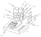
- FIG. 1 is an overall view of a working device according to Embodiment 1 of the present invention.
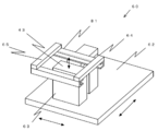
- FIG. 2 is a schematic view of a desktop work device unit according to the apparatus of FIG. 1. It is the schematic of the work table concerning the desktop type work apparatus unit of FIG. It is explanatory drawing explaining the action
- the work device of the present embodiment includes a main body 10 on which the transport unit 30 is disposed and a tabletop work device unit 50 as main components.
- a transport unit 30 that transports the workpiece is provided on the gantry of the main body 10. It is preferable that the transport unit 30 is detachably disposed on the gantry from the viewpoints of maintainability, ease of loading and unloading the desktop work device unit 50, and the like.
- a loader unit that stores a work that has not been completed is disposed at the uppermost stream of the transport unit 30, and an unloader unit that stores a work that has been completed is disposed at the most downstream of the transport unit 30.
- One or more tabletop work device units 50 are arranged in the middle of the transfer unit 30, and the work before the work is carried into the tabletop work device unit 50 and the work from the tabletop work device unit 50 by the transfer unit 30. The work is unloaded.
- the desktop work device unit 50 can be detached from the main body 10 and used alone. When the desktop work device unit 50 is used alone, the work is attached and detached manually. That is, the desktop work device unit 50 includes a work head, a work holding unit, and an XYZ direction moving mechanism, and can be used alone as a semi-automatic work device.
- the tabletop work unit 50 is preferably provided with a work holding part that constitutes a transfer mechanism in conjunction with the transfer unit 30.
- the conveyance rail A80 is provided on the upstream side of the tabletop work apparatus unit 50, and the conveyance rail C82 is provided on the downstream side, and the work holding portion of the tabletop work apparatus unit 50 is configured by the conveyance rail B81 having a work locking mechanism. Disclosed. With such a configuration, it is possible to transfer workpieces between the transfer unit 30 and the desktop work device unit 50 without providing a separate workpiece loading / unloading device.
- the configuration example of the type of apparatus that stores the work discharged from the magazine in the magazine after the application work has been described, but the apparatus configuration that is incorporated in a manufacturing line configured by connecting a plurality of apparatuses in series.
- work was illustrated, it cannot be overemphasized that this invention is not limited to a coating device.
- an arbitrary form can be adopted for the arrangement pattern of the transport rails.
- the present invention can be used for an apparatus that includes a loader, a magazine A, a transport rail A, and a transport rail B, and does not include the transport rail C, the unloader, and the magazine B. That is, the workpiece A applied by the conveyance rail B returns to the magazine A of the loader A again after returning from the conveyance rail A, and then the workpiece B to be applied next is taken out from the magazine A.
- the present invention can also be applied to an apparatus of a type in which a workpiece is conveyed, such as being conveyed to the conveyance rail B via the conveyance rail A. At this time, it goes without saying that the workpiece loading position and the workpiece discharging position are the same position.
- the first embodiment relates to a liquid material application device that applies a liquid material to a lead frame that is a workpiece, and includes a main body 10 in which an operation box 29 and a conveyance unit 30 are disposed, and a tabletop work device unit 50 as main components.
- the workpiece of this embodiment is a lead frame in which a plurality of devices are arranged in a lattice shape, and a hole is formed at the upper right end.
- the main body 10 includes a transport unit 30 and an operation box 29 disposed in front of a base (frame) A11, and a touch panel 14 and a dispense controller 15 on a plate 13 supported by two side plates 12 behind the base A11. Composed.
- a control unit A90 is disposed below the base A11.
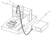
- a desktop work device unit 50 is disposed in the center of the base A11.
- the desktop work device unit 50 includes an X-direction moving mechanism 53 supported by a support column 52 extending above the base B 51, a Z-direction moving mechanism 54 that can be moved in the X direction by the X-direction moving mechanism 53, and a Z-direction moving mechanism. 54, which is movable in the Z direction by the discharge head 56, the CCD camera 57 and the laser displacement meter 58, the Y direction moving mechanism 59 disposed in the center of the base B 51, and the Y direction moving mechanism 59.
- the work table 60 is movable in the direction, and the operation switch 61 is provided on the right side of the base B51.
- a control unit B91 (not shown) is disposed in the base B51.
- the control unit B91 can record a coating program, and the pressing of the operation switch 61 or the coating program (not shown) is a program of an operation sequence for performing coating at a desired position on the workpiece, and X movement It is possible to control the operation of the direction means 53, the Y direction moving mechanism 59 and the Z direction moving mechanism 54, the operation of the dispense controller 15 and a backup unit 63 which will be described later.
- the application program can be executed by receiving a signal from the connector. When the program is executed, the X-direction moving mechanism 53, the Y-direction moving mechanism 59, the Z-direction moving mechanism 54, the dispense controller 15, and the backup unit 63 operate according to the procedure described in the program.
- the control unit B91 is connected to the control unit A described later, and can transmit and receive signals to and from the control unit A.
- the discharge head 56 has a nozzle 17 that communicates with the syringe 16 that stores the liquid material, and communicates with the dispense controller 15 via the tube 18. By pressurizing the liquid material in the syringe 16 for a desired time with the air adjusted by the dispense controller 15, the liquid material is discharged from the nozzle 17.
- the work table 60 includes a stage 62, a support tool 64 disposed on the stage 62, a connection tool 65 supported by the support tool 64, and a second rail member formed by the connection tool 65.
- the transport rail B81 is fixed, and the backup unit 63 is disposed below the transport rail B81 and disposed on the stage 62.
- the conveyance rail B81 is arranged so that the respective recesses of the two rail members having a U-shaped cross section face each other, and a suitable interval is maintained for conveying the workpiece.
- the backup unit 63 has a fixed plate 43 that can move up and down. As shown in FIG. 4, the backup unit 63 brings the fixing plate 43 into contact with the lower surface of the work A20 and raises the work A20 so that the work A20 is closely attached to the transport rail B81.
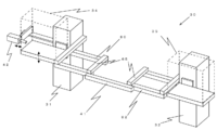
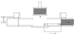
- the transport unit 30 includes a loader unit 31, an unloader unit 32, a transport rail A 80 and a transport rail C 82, and a reciprocating transport unit 33.
- the loader unit 31 can be installed with a magazine A34 that can store 20 lead frames as workpieces, and the magazine A34 is moved up and down by an elevating means (elevating mechanism) (not shown) to sequentially move the lead frames one by one. It sends out to the conveyance rail A80.
- the unloader unit 32 can be installed with the same magazine B35 as the loader unit 31, and stores the lead frames one by one in order by lifting means (not shown) that moves the magazine B35 up and down.
- the transport rail A80 is fixed to the loader unit 31, and is connected to the transport rail C82 fixed to the unloader unit 32 by the rail connector 41.
- the rail connector 41 is fixed to the outer surface side portions of the transport rail A80 and the transport rail C82.
- the transport rail A80 and the transport rail C82 are spaced apart from each other by substantially the same length as the transport rail B81.
- the reciprocating conveyance unit 33 moves in the vertical direction via a conveyance plate 44 that moves in the X direction by a conveyance drive mechanism (conveyance drive means) 36, and a pin attachment 39 fixed to the conveyance plate 44.
- It consists of a pin A37 and a pin B38 that can be attached.
- a pin A 37 is attached to the loader portion 31 side (magazine A 34 side), and a pin B 38 is attached to the unloader portion 32 side (magazine B 35 side).
- the pin attachment 39 to which the pin B38 is attached is provided with a payout plate (pressing member) 40 on the front surface of the pin attachment 39 in the work feeding direction.
- the control unit A90 controls the transport unit 30.
- the control unit A90 controls the vertical movement of each lifting means that moves the loader unit 31 and the unloader unit 32 in the vertical direction, and the X direction movement control of the conveyance drive mechanism 36 that moves the conveyance plate 44 in the X direction.
- the vertical movement control of A37 and pin B38 is performed.
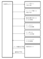
- the control unit A90 communicates with the control unit B91 of the tabletop work apparatus unit 50 about a signal relating to workpiece transfer (see FIG. 8).
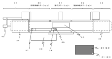
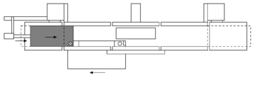
- FIGS. 7a to 7h The operation of the apparatus will be described with reference to FIGS. 7a to 7h.
- the girders for carrying the respective transport rails are not shown.
- the present apparatus starts the coating work.
- the magazine A80 of the loader unit 31 moves to a position where the uppermost first stage work of the magazine A80 is ejected, and then the pusher 42 moves the work A20 toward the transport rail A80 by a specified amount.
- the X direction right direction.
- the pin A37 is inserted into the hole 21 provided at the right end of the work A20.
- the transport driving mechanism 36 is operated, and the work A20 having the pin A37 inserted is slid in the X direction (right direction in the drawing) on the transport rail A80 and moved to the transport rail B81.
- the conveyance drive mechanism 36 is stopped to stop the movement of the workpiece A20.
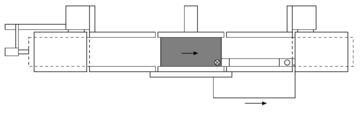
- the tabletop work apparatus unit 50 moves the work to the pattern production work position 72 (see FIG. 7e), and moves the X direction moving mechanism 53 and the Y direction.
- the mechanism 59, the Z-direction moving mechanism 54, and the dispense controller 15 are operated to apply a desired amount of liquid material on the workpiece A20 in a desired pattern.
- the control unit B91 of the tabletop work unit 50 moves the work table 60 to the work carry-out position 71 and transmits an application completion signal to the control unit A90 (see FIG. 7f).
- the work carry-in position 70 and the work carry-out position 71 are the same position, but it goes without saying that the work carry-in position 70 and the work carry-out position 71 may be different positions.
- the workpiece loading position is a position where the conveyance rail B is adjacent to the conveyance rail A but separated from the conveyance rail C
- the workpiece unloading position is the conveyance rail.
- B is adjacent to the transport rail C but is separated from the transport rail A, the workpiece loading position and the workpiece unloading position are different.
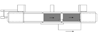
- the transport drive mechanism 36 is moved in the unloader direction (right direction), and the pin B38 is moved to a position where it can be inserted into the hole A21 of the work A20 at the work unloading position, and is put on standby.
- the workpiece B22 inserted through the pin A37 is sent out onto the transport rail A by the movement of the transport drive mechanism 36 in the unloader direction (right direction) and stands by on the transport rail A80.
- the transport rail A80 serves as a coating standby station for a workpiece to be coated next.
- the pin B38 is lowered.
- the control unit A When receiving the application completion signal from the control unit B, the control unit A starts an operation of collecting the applied workpiece A20 in the magazine B35. At the work carry-out position 71, the fixing plate 43 of the backup unit 63 is lowered to release the tight attachment to the work A20. Next, the pin B38 is raised, and the pin B38 is inserted into the hole 21 of the workpiece A20. As shown in FIG. 7g, the work A20 is slid on the transport rail C82 and moved to the transport rail C82 by operating the transport drive mechanism 36 and moving the pin B38 in the direction of the unloader 32 (right direction in the figure). To do. At this time, the workpiece B22 is moved to the transport rail B81 by the pin A37. After the transfer to the transport rail C82, the pin B38 is lowered.
- the payout plate 40 is moved toward the loader unit 31 (shown in the drawing) until the payout plate 40 is closer to the loader than the rear end (left end in the figure) of the workpiece A20.
- the payout plate 40 is moved in the direction of the unloader section 32 (right direction in the figure) by the transport drive mechanism 36 from the rear end (left end in the figure) of the workpiece A20.
- the plate 40 pushes the rear end of the workpiece A20, and stores the workpiece A20 in the magazine B35 of the unloader section 32.
- the magazine B35 of the unloader section 32 is moved to a position for storing the workpiece by the lifting means and is on standby.
- the payout plate 40 is provided at a position where it does not interfere with the unloader side tip (right end in the figure) of the workpiece when the pin B38 penetrates the hole of the workpiece.
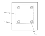
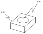
- the tabletop work device unit 50 is formed by inserting four pins disposed on the bottom surface of the tabletop work device unit 50 into the holes 86 of the four blocks 85 fixed on the base A11 of the main body 10. 10 and fixed (see FIGS. 11 and 12). When separating the tabletop work device unit 50 from the main body 10, the tabletop work device unit 50 is lifted upward, and the pins on the bottom surface of the tabletop work device unit 50 are removed from the block 85 of the main body 10.
- the tabletop work device unit 50 can be carried out from the back side of the main body 10 through the area surrounded by the side plate 12 and the top plate 13. It goes without saying that the top plate 13 is provided at a height that does not interfere when the desktop work device unit 50 is carried out.
- a carry-out port may be provided in the base A11 of the main body 10.
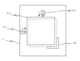
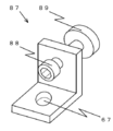
- the desktop work device unit 50 can be positioned and fixed to the main body 10. That is, the tabletop work device unit 50 is placed so that the corner side surface of the tabletop work device unit 50 is positioned in the vicinity of the guide 68 fixed on the base A11 of the main body 10, and then the position adjustment unit 87. Thus, the corner side surface of the desktop work unit 50 can be pressed against the guide 68 to be positioned and fixed.
- the position adjustment unit 87 has a configuration in which a screw 88 having a large diameter at the tip penetrates an L-shaped plate, and the tip surface of the large diameter portion 89 at the tip of the screw 88 is a side surface of the desktop work device unit 50. Abut.
- the large-diameter portion 89 is preferably made of a soft material such as rubber or plastic so as not to damage the tabletop work unit 50.
- a caster is provided on the bottom surface of the tabletop work apparatus unit 50
- the tabletop work apparatus on the base A11 of the main body 10 is used when the position adjustment unit 87 is operated to press the tabletop work apparatus unit 50 against the guide 68. It is preferable because the unit 50 can be easily moved.
- the position adjustment unit 87 is preferably fixed to the base A ⁇ b> 11 of the main body 10 through the attachment hole 67 after the desktop work device unit 50 is placed in the vicinity of the guide 68.
- the table-type work device unit 50 is carried into the main body 10 to the vicinity of the position adjustment unit 87 through the region surrounded by the side plate 12 and the top plate 13. This is because there is no need to lift 50.
- the position adjustment unit 87 is removed from the base A11 in advance, so that the tabletop work unit 50 is lifted from the rear surface of the main body 10 without lifting the table type work unit 50 as in the case of loading. 50 can be carried out.
- the transport unit 30 of this embodiment is directly disposed on the base A11
- the transport unit 30 may be disposed via a member such as a plate that is detachably provided on the base A11.
- a member such as a plate that is detachably provided on the base A11.
- a type of conveyance system in which pins are inserted into holes provided in the workpiece and the workpiece is conveyed is exemplified, but it is needless to say that the present invention is not limited to this conveyance method.
- a conveyance system that conveys a work by sandwiching the work by a clip unit that sandwiches the work instead of a pin in the present embodiment, when holes 21 and 23 are not provided in the work (2) A belt conveyance system in which a work is placed on a rotating belt and conveyed is disclosed.
- the desktop work device unit 50 detached from the main body 10 can be operated as a semi-automatic device.
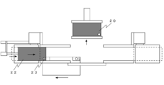
- An example of a usage mode of the desktop work device unit 50 after being detached from the main body 10 is shown in FIG.
- an operator manually sets a work on the work table 60. That is, the worker sets a work on the transport rail B81 of the work table 60, and fixes the work by the backup unit 63 to perform the application work. Similarly, when the work is removed from the work table 60, it is manually performed.
- the program stored (recorded) in the control unit B91 of the desktop work device unit 50 is input by an external input means such as a PC through a connector (not shown). If the desktop robot unit 50 is attached to the main body 10 and connected to the control unit A90, it is possible to input from the monitor (touch panel) 14.
- an arbitrary work head can be selected and used from a discharge head, a cutting tool, a cleaning device, an assembly tool, a screw fastening driver, a UV irradiator, a solder tool, oiling, a press-fitting tool, and the like.
Landscapes
- Engineering & Computer Science (AREA)
- Mechanical Engineering (AREA)
- Automatic Assembly (AREA)
- Coating Apparatus (AREA)
- Feeding Of Workpieces (AREA)
- Supply And Installment Of Electrical Components (AREA)
Priority Applications (3)
| Application Number | Priority Date | Filing Date | Title |
|---|---|---|---|
| CN201080038407.3A CN102497937B (zh) | 2009-08-31 | 2010-08-30 | 作业装置 |
| HK12107291.7A HK1166752B (en) | 2009-08-31 | 2010-08-30 | Operating device |
| KR1020127008287A KR101759589B1 (ko) | 2009-08-31 | 2010-08-30 | 작업 장치 |
Applications Claiming Priority (2)
| Application Number | Priority Date | Filing Date | Title |
|---|---|---|---|
| JP2009201074A JP5586191B2 (ja) | 2009-08-31 | 2009-08-31 | 作業装置 |
| JP2009-201074 | 2009-08-31 |
Publications (1)
| Publication Number | Publication Date |
|---|---|
| WO2011024998A1 true WO2011024998A1 (ja) | 2011-03-03 |
Family
ID=43628089
Family Applications (1)
| Application Number | Title | Priority Date | Filing Date |
|---|---|---|---|
| PCT/JP2010/064701 Ceased WO2011024998A1 (ja) | 2009-08-31 | 2010-08-30 | 作業装置 |
Country Status (5)
| Country | Link |
|---|---|
| JP (1) | JP5586191B2 (enExample) |
| KR (1) | KR101759589B1 (enExample) |
| CN (2) | CN102497937B (enExample) |
| TW (2) | TWI524945B (enExample) |
| WO (1) | WO2011024998A1 (enExample) |
Cited By (2)
| Publication number | Priority date | Publication date | Assignee | Title |
|---|---|---|---|---|
| JP2011050831A (ja) * | 2009-08-31 | 2011-03-17 | Musashi Eng Co Ltd | 作業装置 |
| CN106081612A (zh) * | 2016-07-28 | 2016-11-09 | 昆山优乐智机器人科技有限公司 | 一种自动化点胶热压综合流水线 |
Families Citing this family (5)
| Publication number | Priority date | Publication date | Assignee | Title |
|---|---|---|---|---|
| KR20130136057A (ko) | 2012-06-04 | 2013-12-12 | 현대자동차주식회사 | 차량 운행안내장치 및 방법 |
| JP6585391B2 (ja) | 2015-06-11 | 2019-10-02 | 蛇の目ミシン工業株式会社 | ロボット |
| JP6736754B2 (ja) * | 2017-02-14 | 2020-08-05 | ヤマハ発動機株式会社 | 被実装物作業装置 |
| CN113426626B (zh) * | 2021-05-26 | 2022-10-11 | 沈阳西子航空产业有限公司 | 一种低压入渗式高温环氧胶修补装置 |
| CN113798140B (zh) * | 2021-09-17 | 2023-01-24 | 北京闼闼同创工贸有限公司 | 一种自动生产线 |
Citations (4)
| Publication number | Priority date | Publication date | Assignee | Title |
|---|---|---|---|---|
| JPH04222656A (ja) * | 1990-12-25 | 1992-08-12 | N O K Megurasuteitsuku Kk | 塗装機 |
| JP3472318B2 (ja) * | 1993-02-26 | 2003-12-02 | オリジン電気株式会社 | ディスク用被膜形成装置 |
| JP2005175310A (ja) * | 2003-12-12 | 2005-06-30 | Tokyo Electron Ltd | 基板処理装置 |
| JP2008192718A (ja) * | 2007-02-02 | 2008-08-21 | Dainippon Printing Co Ltd | 基板支持装置、基板支持方法、基板加工装置、基板加工方法、表示装置構成部材の製造方法、検査装置、検査方法 |
Family Cites Families (11)
| Publication number | Priority date | Publication date | Assignee | Title |
|---|---|---|---|---|
| JPH08229478A (ja) * | 1995-02-23 | 1996-09-10 | Nec Eng Ltd | ペースト塗布装置 |
| JPH11238456A (ja) * | 1998-02-20 | 1999-08-31 | Hirata Corp | 基板製造ラインおよび基板製造方法 |
| JPH11309409A (ja) * | 1998-04-30 | 1999-11-09 | Dainippon Screen Mfg Co Ltd | 基板処理システム |
| FR2802127B1 (fr) * | 1999-12-09 | 2002-09-06 | Biodecap Ind | Nouveau plateau technique pour le decapage et/ou la peinture et les ateliers ainsi realises |
| JP4373041B2 (ja) * | 2001-11-14 | 2009-11-25 | 武蔵エンジニアリング株式会社 | 液材塗布装置 |
| JP4262553B2 (ja) * | 2003-08-11 | 2009-05-13 | 武蔵エンジニアリング株式会社 | 卓上型液状内容物分注装置 |
| CN2745661Y (zh) * | 2004-11-24 | 2005-12-14 | 吴发 | 半自动上胶黏合机 |
| CN101321604B (zh) * | 2005-12-06 | 2011-09-14 | 武藏高科技有限公司 | 加工装置及加工方法 |
| CN101439332A (zh) * | 2007-11-20 | 2009-05-27 | 扬动股份有限公司 | 发动机垫片涂胶装置 |
| CN201253602Y (zh) * | 2008-10-26 | 2009-06-10 | 扬州麦斯通复合材料有限公司 | 高粘度胶半自动淋洒料槽 |
| JP5586191B2 (ja) * | 2009-08-31 | 2014-09-10 | 武蔵エンジニアリング株式会社 | 作業装置 |
-
2009
- 2009-08-31 JP JP2009201074A patent/JP5586191B2/ja active Active
-
2010
- 2010-08-30 KR KR1020127008287A patent/KR101759589B1/ko active Active
- 2010-08-30 CN CN201080038407.3A patent/CN102497937B/zh active Active
- 2010-08-30 WO PCT/JP2010/064701 patent/WO2011024998A1/ja not_active Ceased
- 2010-08-30 CN CN201510527742.4A patent/CN105214909B/zh active Active
- 2010-08-31 TW TW099129236A patent/TWI524945B/zh active
- 2010-08-31 TW TW105102056A patent/TWI587926B/zh active
Patent Citations (4)
| Publication number | Priority date | Publication date | Assignee | Title |
|---|---|---|---|---|
| JPH04222656A (ja) * | 1990-12-25 | 1992-08-12 | N O K Megurasuteitsuku Kk | 塗装機 |
| JP3472318B2 (ja) * | 1993-02-26 | 2003-12-02 | オリジン電気株式会社 | ディスク用被膜形成装置 |
| JP2005175310A (ja) * | 2003-12-12 | 2005-06-30 | Tokyo Electron Ltd | 基板処理装置 |
| JP2008192718A (ja) * | 2007-02-02 | 2008-08-21 | Dainippon Printing Co Ltd | 基板支持装置、基板支持方法、基板加工装置、基板加工方法、表示装置構成部材の製造方法、検査装置、検査方法 |
Cited By (2)
| Publication number | Priority date | Publication date | Assignee | Title |
|---|---|---|---|---|
| JP2011050831A (ja) * | 2009-08-31 | 2011-03-17 | Musashi Eng Co Ltd | 作業装置 |
| CN106081612A (zh) * | 2016-07-28 | 2016-11-09 | 昆山优乐智机器人科技有限公司 | 一种自动化点胶热压综合流水线 |
Also Published As
| Publication number | Publication date |
|---|---|
| JP2011050831A (ja) | 2011-03-17 |
| TW201622833A (zh) | 2016-07-01 |
| JP5586191B2 (ja) | 2014-09-10 |
| CN102497937B (zh) | 2015-09-02 |
| HK1214203A1 (zh) | 2016-07-22 |
| KR101759589B1 (ko) | 2017-07-19 |
| TWI524945B (zh) | 2016-03-11 |
| KR20120059595A (ko) | 2012-06-08 |
| CN105214909A (zh) | 2016-01-06 |
| CN105214909B (zh) | 2018-02-02 |
| HK1166752A1 (en) | 2012-11-09 |
| CN102497937A (zh) | 2012-06-13 |
| TWI587926B (zh) | 2017-06-21 |
| TW201119747A (en) | 2011-06-16 |
Similar Documents
| Publication | Publication Date | Title |
|---|---|---|
| JP5586191B2 (ja) | 作業装置 | |
| CN102762312B (zh) | 桌上型作业装置 | |
| JP6659682B2 (ja) | 印刷装置 | |
| WO2015037099A1 (ja) | 対基板作業システム、作業方法、およびフィーダ移し替え方法 | |
| CN101321604B (zh) | 加工装置及加工方法 | |
| JP2011050831A5 (enExample) | ||
| KR101297125B1 (ko) | 유리가공장치 및 그 제어방법 | |
| CN103415352A (zh) | 液体涂覆装置和液体涂覆方法 | |
| WO2000040344A1 (en) | System and method for interchangeably interfacing wet components with a coating apparatus | |
| JP5344645B2 (ja) | 生産ライン | |
| CN119767544A (zh) | 一种用于电子零件加工的自动化下料设备及方法 | |
| HK1214203B (zh) | 作业装置 | |
| HK1166752B (en) | Operating device | |
| JP7069565B2 (ja) | ワーク供給装置及びワーク加工システム | |
| JP2023144865A (ja) | 部品実装システム | |
| KR101346377B1 (ko) | 기판 장착 장치 및 방법, 및 이를 구비한 코팅 장치 및 방법 | |
| JPH11254188A (ja) | 板材加工機におけるワーク搬入出装置 | |
| JP2003205332A (ja) | ワーク積込装置及びそのアタッチメント交換方法 | |
| CN119077572A (zh) | 一种硬质合金材料加工用一体化设备及其使用方法 | |
| JPH06210216A (ja) | 接着剤塗布装置 | |
| HK1124012B (en) | Machining apparatus and machining method |
Legal Events
| Date | Code | Title | Description |
|---|---|---|---|
| WWE | Wipo information: entry into national phase |
Ref document number: 201080038407.3 Country of ref document: CN |
|
| 121 | Ep: the epo has been informed by wipo that ep was designated in this application |
Ref document number: 10812044 Country of ref document: EP Kind code of ref document: A1 |
|
| DPE1 | Request for preliminary examination filed after expiration of 19th month from priority date (pct application filed from 20040101) | ||
| NENP | Non-entry into the national phase |
Ref country code: DE |
|
| ENP | Entry into the national phase |
Ref document number: 20127008287 Country of ref document: KR Kind code of ref document: A |
|
| 122 | Ep: pct application non-entry in european phase |
Ref document number: 10812044 Country of ref document: EP Kind code of ref document: A1 |