WO2011024678A1 - 回転角度センサ - Google Patents
回転角度センサ Download PDFInfo
- Publication number
- WO2011024678A1 WO2011024678A1 PCT/JP2010/063902 JP2010063902W WO2011024678A1 WO 2011024678 A1 WO2011024678 A1 WO 2011024678A1 JP 2010063902 W JP2010063902 W JP 2010063902W WO 2011024678 A1 WO2011024678 A1 WO 2011024678A1
- Authority
- WO
- WIPO (PCT)
- Prior art keywords
- coil
- output
- magnetic pole
- angle sensor
- yoke
- Prior art date
- Legal status (The legal status is an assumption and is not a legal conclusion. Google has not performed a legal analysis and makes no representation as to the accuracy of the status listed.)
- Ceased
Links
Images


Classifications
-
- G—PHYSICS
- G01—MEASURING; TESTING
- G01D—MEASURING NOT SPECIALLY ADAPTED FOR A SPECIFIC VARIABLE; ARRANGEMENTS FOR MEASURING TWO OR MORE VARIABLES NOT COVERED IN A SINGLE OTHER SUBCLASS; TARIFF METERING APPARATUS; MEASURING OR TESTING NOT OTHERWISE PROVIDED FOR
- G01D5/00—Mechanical means for transferring the output of a sensing member; Means for converting the output of a sensing member to another variable where the form or nature of the sensing member does not constrain the means for converting; Transducers not specially adapted for a specific variable
- G01D5/12—Mechanical means for transferring the output of a sensing member; Means for converting the output of a sensing member to another variable where the form or nature of the sensing member does not constrain the means for converting; Transducers not specially adapted for a specific variable using electric or magnetic means
- G01D5/14—Mechanical means for transferring the output of a sensing member; Means for converting the output of a sensing member to another variable where the form or nature of the sensing member does not constrain the means for converting; Transducers not specially adapted for a specific variable using electric or magnetic means influencing the magnitude of a current or voltage
- G01D5/20—Mechanical means for transferring the output of a sensing member; Means for converting the output of a sensing member to another variable where the form or nature of the sensing member does not constrain the means for converting; Transducers not specially adapted for a specific variable using electric or magnetic means influencing the magnitude of a current or voltage by varying inductance, e.g. by a movable armature
- G01D5/204—Mechanical means for transferring the output of a sensing member; Means for converting the output of a sensing member to another variable where the form or nature of the sensing member does not constrain the means for converting; Transducers not specially adapted for a specific variable using electric or magnetic means influencing the magnitude of a current or voltage by varying inductance, e.g. by a movable armature by influencing the mutual induction between two or more coils
- G01D5/2046—Mechanical means for transferring the output of a sensing member; Means for converting the output of a sensing member to another variable where the form or nature of the sensing member does not constrain the means for converting; Transducers not specially adapted for a specific variable using electric or magnetic means influencing the magnitude of a current or voltage by varying inductance, e.g. by a movable armature by influencing the mutual induction between two or more coils by a movable ferromagnetic element, e.g. a core
Definitions
- the present invention relates to a rotation angle sensor.
- a technique has been disclosed in which the number of coil turns wound on the stator is disposed on the SIN distribution, and machine winding is enabled (see, for example, Patent Document 1).
- Patent Document 1 and Patent Document 2 of the prior art in order to form a stator including a magnetic pole unit by stacking a plurality of stators formed by pressing from one electromagnetic steel sheet, the inner periphery where a rotor is disposed There was a problem that the electromagnetic steel sheet of part was not used and the yield was low.
- a coil since a coil must be wound on each of a plurality of protrusions located on the inner periphery of the stator, a special winding machine is required, and at the same time a complex winding process is required, the tact time is There was a problem that became long.
- the stators located on the outer side of the rotor are magnetically coupled, there is a problem that magnetic interference occurs between adjacent coils and an error occurs in the output.
- the present invention has been made in view of the above problems, and an object of the present invention is to provide a rotation angle sensor capable of achieving a high yield of magnetic steel sheets, shortening tact time, and reducing magnetic field interference.
- the first problem solving means taken to solve the above-mentioned problems comprises a rotor composed of magnetic material, having N salient poles or N cycles of sinusoidal gap permeance, an exciting coil and a COS output. And a plurality of magnetic pole units disposed directly or indirectly on the yoke, with at least one of the first output coil to be obtained and the second output coil to obtain SIN output, and a plurality of magnetic pole units arranged around the rotor.
- the magnetic pole unit forms an independent closed magnetic circuit.
- the second problem solution means obtains a rotor having N salient poles or N cycles of sinusoidal gap permeance and made of magnetic material, a first output coil for obtaining an exciting coil and a COS output, and a SIN output.
- a rotational angle sensor comprising: a plurality of magnetic pole units wound directly or indirectly around the rotor with at least one of the second output coils directly or indirectly; It is to be fixed to a magnetic body.
- a third problem solving means is that the yoke has a U-shape.
- a fourth problem-solving means is that the magnetic pole unit is disposed such that a U-shaped opening of the yoke faces the rotor.
- a fifth problem solving means is that the exciting coil, the first output coil, and the second output coil are wound around a U-shaped bent portion of the yoke.
- a sixth means for solving the problem is that the number of turns of the first output coil and the number of turns of the second output coil are the same.
- a seventh problem-solving means is that the magnetic pole unit is disposed at a constant distance from the rotation axis of the rotor.
- An eighth problem solving means is that the rotor does not have a winding, and (N ⁇ Y) magnetic pole units are arranged.
- the rotation angle sensor of the present invention is composed of a plurality of individual magnetic pole units, it is possible to increase the yield of the electromagnetic steel sheet in which the yoke constituting the magnetic pole unit is formed.
- the magnetic pole units become independent, the magnetic pole units form independent closed magnetic paths, magnetic field interference with the adjacent magnetic pole units is reduced, and the detection accuracy of the rotation angle is improved.
- the yield of the magnetic steel sheets constituting the yoke can be increased. Then, since the magnetic pole units are fixed to the nonmagnetic material, the magnetic pole units form independent closed magnetic paths, magnetic field interference with the adjacent magnetic pole units is reduced, and the detection accuracy of the rotation angle is improved.
- the exciting coil and the output coil can be wound by rotating the yoke without using a special winding machine.
- the supply tension of the coil wire at the time of winding and the feed pitch in the axial direction can be made accurate, and the aligned winding in which the space factor of the coil is stable becomes possible. Therefore, the output fluctuation due to the variation of the coil space factor is reduced, and the detection accuracy of the rotation angle is improved.
- the magnetic pole unit is disposed such that the U-shaped opening of the yoke faces the rotor, the gap between the U-shaped yoke and the rotor changes.
- the rotor angle can be detected by comparing the two outputs of the COS waveform and the SIN waveform generated in the output coil and the second output coil.
- the exciting coil, the first output coil and the second output coil are wound around the U-shaped bent portion of the yoke, the yoke is rotated without using a special winding machine, and the exciting coil and the first output coil are One output coil and a second output coil can be wound up.
- the supply tension of the coil wire at the time of winding and the feed pitch in the axial direction can be made accurate, and the aligned winding in which the space factor of the coil is stable becomes possible. Therefore, the impedance generated from the coil at the time of driving the rotation angle sensor is reduced, and the output is improved.
- the number of turns of the first output coil and the number of turns of the second output coil are the same, it is possible to simultaneously wind the output coil around the yoke around which the first output coil is wound and the yoke around which the second output coil is wound Tact time is reduced.
- the yield of the electromagnetic steel sheet can be increased.
- the magnetic pole units since the magnetic pole units become independent, the magnetic pole units form independent closed magnetic paths, magnetic field interference with the adjacent magnetic pole units is reduced, and the detection accuracy of the rotation angle is improved.
- the rotor does not have a winding, and by arranging (N ⁇ Y) magnetic pole units, the yield of the electromagnetic steel sheet can be increased.
- the magnetic pole units since the magnetic pole units become independent, the magnetic pole units form independent closed magnetic paths, magnetic field interference with the adjacent magnetic pole units is reduced, and the detection accuracy of the rotation angle is improved.
- FIG. 3 is a cross-sectional view of the magnetic pole unit in the present invention taken along the line AA It is a wiring diagram of each coil in the present invention. It is an example of the output result of the rotation angle sensor in this invention. It is a block diagram of the rotation angle sensor in conventional structure. It is a graph of the result of having performed magnetic field analysis to the rotation angle sensor in conventional structure. It is a graph of the result of having performed magnetic field analysis to the rotation angle sensor in the present invention.
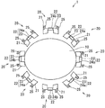
- FIG. 1 is a block diagram of a rotation angle sensor 1 in the present invention.
- the rotation angle sensor 1 according to the present embodiment has an elliptical rotor 10 having N salient poles or N cycles of sinusoidal gap permeance and made of a magnetic material, an exciting coil 23, and a COS output.
- At least one coil 22 of the first output coil 24a or the second output coil 24b for obtaining a SIN output is wound around the yoke 21 and (N ⁇ Y) (Y is 4) at a fixed distance from the rotation axis of the rotor 10
- the magnetic pole unit 20 disposed. That is, the magnetic pole unit 20 is disposed around the rotor 10 (outside the outer periphery of the rotor 10).
- the number of magnetic pole units 20 to be arranged is eight, but by changing the number of N and Y, the shape of the rotor 10 and the number of magnetic pole units 20 can be obtained. It is possible to change and design. Further, as the value of Y increases, the number of magnetic pole units increases, so the output accuracy also improves. Further, even in the case where the winding is directly wound on the yoke 21, the same effect can be obtained even in the case where the yoke 21 is covered with a bobbin made of a resin material and the winding is wound indirectly on the outer periphery of the bobbin.
- the plurality of magnetic pole units 20 may be detachably disposed at a constant distance from the rotation axis of the rotor 10 outside the circumference of the rotor 10, or may be disposed in a state where they are fixed. . Further, as a fixing method of the stopper 25, a method of fixing using a screw or a nut using a hole, a method of inserting the stopper 25 into a member to be fixed, and the like are used.
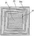
- FIG. 2 is a block diagram of the magnetic pole unit 20 in the present invention.
- the magnetic pole unit 20 used in the present invention has a U-shaped yoke 21 and a coil 22 wound around a bent portion 27 of the yoke 21 (excitation coil 23 and first output coil 24a (or second output coil 24b)) And a stopper 25 at the end of the yoke 21.
- the magnetic pole unit 20 is disposed such that the opening 26 faces the rotor 10 as shown in FIG. 4 by the fixing method of the stopper 25 described above.
- the yoke 21 of this embodiment has a configuration in which 12 pressed magnetic steel sheets are stacked and integrated by welding or the like.
- the shape of the yoke 21 is expressed as a U-shape, but the U-shape includes a C-shape, a U-shape, a horseshoe shape or the like.
- FIG. 3 is a cross-sectional view of the magnetic pole unit 20 in the present invention taken along the line AA.
- the exciting coil 23 is wound around the bent portion 27 of the yoke 21, and the first output coil 24a (or the second output coil 24b) is wound thereon.
- Table 1 shows an example of the number of turns of the exciting coil 23 and the first output coil 24a (or the second output coil 24b) wound around each yoke 21 and how to wind them.
- the yoke names (A) to (H) correspond to (A) to (H) in FIG. 4 described later.
- the minus notation in Table 1 means reverse winding with respect to the winding direction of the coil in the number of turns not minus notation.
- COS and “SIN” of “the number of turns of output coil” in Table 1 respectively mean so-called “COS winding” and “SIN winding”, and in the present embodiment, the first output for obtaining the COS output respectively
- the coil 24a corresponds to the second output coil 24b that obtains the SIN output.
- the number of turns of the coil may be a distributed winding (the number of turns of the coil also has a sinusoidal distribution) such that the induced electromotive voltage distribution has a sine wave distribution. The same effect as that of the embodiment can be obtained.
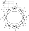
- FIG. 4 is a wiring diagram of the exciting coil 23, the first output coil 24a, and the second output coil 24b in the present invention.
- the exciting coil 23 is electrically connected in series.
- the plurality of magnetic pole units 20 and yokes 21 in FIG. 4 will be described with reference to (A) to (H) as shown in FIG.
- the first output coils 24a wound around the yoke 21 (C), the yoke 21 (E), the yoke 21 (G), and the yoke 21 (A) are electrically connected in series as shown in FIG.
- the second output coil 24b wound around each of the yoke 21 (B), the yoke 21 (D), the yoke 21 (F) and the yoke 21 (H) is electrically connected in series as shown in FIG. Ru.
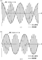
- FIG. 5 is an example of the output result of the rotation angle sensor in the present invention.
- FIG. 5 (I) is an example of the output result by the first output coil 24a
- FIG. 5 (II) is an example of the output result by the second output coil 24b.
- the horizontal axis represents the rotation angle ⁇ of the rotor 10
- the vertical axis represents the voltage value V obtained from the first output coil 24a and the second output coil 24b.
- a sine wave voltage of, for example, 10 kHz and 10 V is excited in the exciting coil 23.
- the rotation of the rotor 10 changes the gap between the rotor 10 and the yoke 21 of the magnetic pole unit 20 disposed at a constant distance from the rotation axis of the rotor 10.
- the magnetic resistance of the yoke 21 changes, and the output voltage generated in the first output coil 24a and the second output coil 24b changes in a sine wave. Since the first output coil 24a and the second output coil 24b are arranged to be changed by 45 degrees in mechanical angle, this structure having an axis double angle 2X changes the phase by 90 degrees and outputs as shown in FIG. .
- the angle of the rotor 10 can be detected by comparing the two outputs of the obtained COS waveform and SIN waveform.
- FIG. 6 shows a rotation angle sensor 30 of a conventional structure.
- the rotor 40, the stator 50, and the 14 pole units 51 projecting on the inner periphery of the stator 50 are provided. The respective positions will be described with reference to (a) to (n).
- the magnetic pole unit 51 includes a coil 52 that is the excitation coil 53 and at least one of the first output coil 54a and the second output coil 54b.
- FIG. 7 is a graph of the result of magnetic field analysis performed on the rotation angle sensor 30 in the conventional structure of FIG. The analysis was performed by winding the coil 52 only on the magnetic pole unit 51 (g).
- the horizontal axis indicates the magnetic pole unit, and the vertical axis indicates the linkage magnetic field. Since the magnetic pole unit 51 is magnetically connected to the stator 50, there is a magnetic flux leakage of about 8% to the magnetic pole unit 51 (f) and the magnetic pole unit 51 (h) adjacent to the magnetic pole unit 51 (g).
- the magnetic pole units 51 (a) to (n) as a whole had a magnetic flux leakage of about 52.4%.
- FIG. 8 is a graph of the result of magnetic field analysis of the rotation angle sensor 1 of the present invention.
- the analysis was performed by winding the coil 22 only on the magnetic pole unit 20 (D) in FIG.
- the horizontal axis indicates the magnetic pole unit, and the vertical axis indicates the linkage magnetic field. Since the magnetic pole unit 20 is magnetically independent, the magnetic flux leakage should be suppressed to about 0.3% with respect to the magnetic pole unit 20 (C) and the magnetic pole unit 20 (E) adjacent to the magnetic pole unit 20 (D). It was possible. Further, the magnetic flux leakage could be suppressed to about 0.65% in the entire magnetic pole units 20 (A) to (H).
- the yield of the magnetic steel sheets can be increased and the cost can be reduced.
- the yoke 21 has a U-shape
- the coil 22 can be wound by rotating the yoke 21.
- the supply tension of the coil wire at the time of winding and the feed pitch in the axial direction can be made accurate, and the aligned winding in which the space factor of the coil is stable becomes possible. Therefore, the output fluctuation due to the variation of the coil space factor is reduced, and the detection accuracy of the rotation angle is improved.
- the coil 22 is wound in two ways in the forward and reverse directions and the number of turns is equal, at least one of the exciting coil 23 and the first output coil 24 a or the second output coil 24 b is used as the plurality of yokes 21.
- the same type of winding coil can be wound simultaneously, it is possible to shorten the tact time.
- a member for fixing the plurality of magnetic pole units 20 it is possible to use a nonmagnetic metal such as aluminum or a nonmagnetic member such as resin. By fixing to the nonmagnetic member as described above, it is possible to suppress the leakage of the magnetic flux, and since each of the magnetic pole units 20 is magnetically independent, the error due to the magnetic flux leakage occurring at the time of driving the rotation angle sensor 1 It becomes possible to prevent.
- the magnetic pole unit 20 is disposed so that the U-shaped opening 26 of the yoke 21 faces the rotor 10, and the gap between the U-shaped yoke 21 and the rotor 10 is As it changes, two outputs of the COS waveform and the SIN waveform are generated in the first output coil 24a and the second output coil 24b, respectively.
- the rotation angle of the rotor 10 can be detected by comparing and processing the COS waveform signal and the SIN waveform signal.
- the exciting coil 23, the first output coil 24a, and the second output coil 24b are wound around the U-shaped bent portion 27 of the yoke 21 as described above, the yoke 21 is not used, and a special winding machine is not used. By winding the exciting coil 23, the first output coil 24a, and the second output coil 24b, thereby winding the exciting coil 23, the first output coil 24a, and the second output coil 24b around the yoke 21. it can.
- the present invention is applicable to a rotation angle sensor that detects the rotation angle of a rotor.
Landscapes
- Physics & Mathematics (AREA)
- General Physics & Mathematics (AREA)
- Transmission And Conversion Of Sensor Element Output (AREA)
Applications Claiming Priority (4)
| Application Number | Priority Date | Filing Date | Title |
|---|---|---|---|
| JP2009-200210 | 2009-08-31 | ||
| JP2009200210 | 2009-08-31 | ||
| JP2010156427A JP2011069811A (ja) | 2009-08-31 | 2010-07-09 | 回転角度センサ |
| JP2010-156427 | 2010-07-09 |
Publications (1)
| Publication Number | Publication Date |
|---|---|
| WO2011024678A1 true WO2011024678A1 (ja) | 2011-03-03 |
Family
ID=43627783
Family Applications (1)
| Application Number | Title | Priority Date | Filing Date |
|---|---|---|---|
| PCT/JP2010/063902 Ceased WO2011024678A1 (ja) | 2009-08-31 | 2010-08-18 | 回転角度センサ |
Country Status (2)
| Country | Link |
|---|---|
| JP (1) | JP2011069811A (enExample) |
| WO (1) | WO2011024678A1 (enExample) |
Families Citing this family (1)
| Publication number | Priority date | Publication date | Assignee | Title |
|---|---|---|---|---|
| JP2021060263A (ja) * | 2019-10-07 | 2021-04-15 | 多摩川精機株式会社 | 二重冗長系レゾルバ |
Citations (4)
| Publication number | Priority date | Publication date | Assignee | Title |
|---|---|---|---|---|
| JP2003207370A (ja) * | 2002-01-11 | 2003-07-25 | Okuma Corp | リラクタンス型レゾルバ |
| JP2003287441A (ja) * | 2002-03-27 | 2003-10-10 | Minebea Co Ltd | 回転位置検出器 |
| JP2007285774A (ja) * | 2006-04-13 | 2007-11-01 | Toyota Motor Corp | 磁気レゾルバ及びその製造方法 |
| JP2009174925A (ja) * | 2008-01-22 | 2009-08-06 | Tamagawa Seiki Co Ltd | 回転角度検出装置 |
Family Cites Families (3)
| Publication number | Priority date | Publication date | Assignee | Title |
|---|---|---|---|---|
| JPH065161B2 (ja) * | 1984-08-23 | 1994-01-19 | 株式会社エスジー | 分離されたステータコアを有する誘導形位置検出器 |
| JP2006023146A (ja) * | 2004-07-07 | 2006-01-26 | Honda Motor Co Ltd | 回転位置検出装置 |
| JP2008175553A (ja) * | 2007-01-16 | 2008-07-31 | Tamagawa Seiki Co Ltd | 角度検出器 |
-
2010
- 2010-07-09 JP JP2010156427A patent/JP2011069811A/ja active Pending
- 2010-08-18 WO PCT/JP2010/063902 patent/WO2011024678A1/ja not_active Ceased
Patent Citations (4)
| Publication number | Priority date | Publication date | Assignee | Title |
|---|---|---|---|---|
| JP2003207370A (ja) * | 2002-01-11 | 2003-07-25 | Okuma Corp | リラクタンス型レゾルバ |
| JP2003287441A (ja) * | 2002-03-27 | 2003-10-10 | Minebea Co Ltd | 回転位置検出器 |
| JP2007285774A (ja) * | 2006-04-13 | 2007-11-01 | Toyota Motor Corp | 磁気レゾルバ及びその製造方法 |
| JP2009174925A (ja) * | 2008-01-22 | 2009-08-06 | Tamagawa Seiki Co Ltd | 回転角度検出装置 |
Also Published As
| Publication number | Publication date |
|---|---|
| JP2011069811A (ja) | 2011-04-07 |
Similar Documents
| Publication | Publication Date | Title |
|---|---|---|
| JP5058849B2 (ja) | ブラシレスモータ | |
| JP4654348B1 (ja) | 検出装置用巻線の正弦波巻線方法 | |
| JP4775294B2 (ja) | レゾルバ | |
| US8269487B2 (en) | Sheet coil type resolver | |
| JP2009213284A (ja) | ブラシレスモータ | |
| JP2002168652A (ja) | nXリラクタンスレゾルバ | |
| US20200395875A1 (en) | Multigroup-multiphase rotary electrical machine control device and multigroup-multiphase rotary electrical machine drive device | |
| US7183952B1 (en) | Resolver | |
| CN103890546A (zh) | 用于磁阻式传感器的磁通量增强器系统 | |
| JP5711791B2 (ja) | 直流モータ | |
| KR20140057078A (ko) | 리졸버 및 그 제조 방법 | |
| EP3799277B1 (en) | Rotary transformer | |
| JP6504261B2 (ja) | 電動機の回転子の製造方法及び製造装置 | |
| JP6529662B2 (ja) | レゾルバ | |
| US9441942B2 (en) | Resolver and multiple-rotation detector | |
| WO2011024678A1 (ja) | 回転角度センサ | |
| US20210119497A1 (en) | Electric motor | |
| JP5363136B2 (ja) | ブラシレスモータ | |
| JP4882513B2 (ja) | 回転角検出装置およびトルクセンサ | |
| US11552534B2 (en) | Resolver device and rotating electrical machine with resolver device | |
| JP2009300238A (ja) | 可変リラクタンス型レゾルバ | |
| JP6976243B2 (ja) | レゾルバ | |
| JP5024893B2 (ja) | 可変リラクタンス型レゾルバ | |
| JP2013027130A (ja) | レゾルバ | |
| JP5182759B2 (ja) | レゾルバー及びレゾルバーの製造方法 |
Legal Events
| Date | Code | Title | Description |
|---|---|---|---|
| 121 | Ep: the epo has been informed by wipo that ep was designated in this application |
Ref document number: 10811728 Country of ref document: EP Kind code of ref document: A1 |
|
| NENP | Non-entry into the national phase |
Ref country code: DE |
|
| 122 | Ep: pct application non-entry in european phase |
Ref document number: 10811728 Country of ref document: EP Kind code of ref document: A1 |