WO2011016551A1 - 冷凍機の運転管理装置 - Google Patents
冷凍機の運転管理装置 Download PDFInfo
- Publication number
- WO2011016551A1 WO2011016551A1 PCT/JP2010/063378 JP2010063378W WO2011016551A1 WO 2011016551 A1 WO2011016551 A1 WO 2011016551A1 JP 2010063378 W JP2010063378 W JP 2010063378W WO 2011016551 A1 WO2011016551 A1 WO 2011016551A1
- Authority
- WO
- WIPO (PCT)
- Prior art keywords
- power consumption
- group
- defrosting
- time
- refrigerator
- Prior art date
- Legal status (The legal status is an assumption and is not a legal conclusion. Google has not performed a legal analysis and makes no representation as to the accuracy of the status listed.)
- Ceased
Links
Images





Classifications
-
- F—MECHANICAL ENGINEERING; LIGHTING; HEATING; WEAPONS; BLASTING
- F25—REFRIGERATION OR COOLING; COMBINED HEATING AND REFRIGERATION SYSTEMS; HEAT PUMP SYSTEMS; MANUFACTURE OR STORAGE OF ICE; LIQUEFACTION SOLIDIFICATION OF GASES
- F25B—REFRIGERATION MACHINES, PLANTS OR SYSTEMS; COMBINED HEATING AND REFRIGERATION SYSTEMS; HEAT PUMP SYSTEMS
- F25B49/00—Arrangement or mounting of control or safety devices
- F25B49/005—Arrangement or mounting of control or safety devices of safety devices
-
- F—MECHANICAL ENGINEERING; LIGHTING; HEATING; WEAPONS; BLASTING
- F25—REFRIGERATION OR COOLING; COMBINED HEATING AND REFRIGERATION SYSTEMS; HEAT PUMP SYSTEMS; MANUFACTURE OR STORAGE OF ICE; LIQUEFACTION SOLIDIFICATION OF GASES
- F25D—REFRIGERATORS; COLD ROOMS; ICE-BOXES; COOLING OR FREEZING APPARATUS NOT OTHERWISE PROVIDED FOR
- F25D21/00—Defrosting; Preventing frosting; Removing condensed or defrost water
- F25D21/002—Defroster control
- F25D21/006—Defroster control with electronic control circuits
-
- F—MECHANICAL ENGINEERING; LIGHTING; HEATING; WEAPONS; BLASTING
- F25—REFRIGERATION OR COOLING; COMBINED HEATING AND REFRIGERATION SYSTEMS; HEAT PUMP SYSTEMS; MANUFACTURE OR STORAGE OF ICE; LIQUEFACTION SOLIDIFICATION OF GASES
- F25B—REFRIGERATION MACHINES, PLANTS OR SYSTEMS; COMBINED HEATING AND REFRIGERATION SYSTEMS; HEAT PUMP SYSTEMS
- F25B2400/00—Component parts or details not otherwise provided for in this subclass
- F25B2400/22—Refrigeration systems for supermarkets
-
- F—MECHANICAL ENGINEERING; LIGHTING; HEATING; WEAPONS; BLASTING
- F25—REFRIGERATION OR COOLING; COMBINED HEATING AND REFRIGERATION SYSTEMS; HEAT PUMP SYSTEMS; MANUFACTURE OR STORAGE OF ICE; LIQUEFACTION SOLIDIFICATION OF GASES
- F25B—REFRIGERATION MACHINES, PLANTS OR SYSTEMS; COMBINED HEATING AND REFRIGERATION SYSTEMS; HEAT PUMP SYSTEMS
- F25B2500/00—Problems to be solved
- F25B2500/26—Problems to be solved characterised by the startup of the refrigeration cycle
-
- F—MECHANICAL ENGINEERING; LIGHTING; HEATING; WEAPONS; BLASTING
- F25—REFRIGERATION OR COOLING; COMBINED HEATING AND REFRIGERATION SYSTEMS; HEAT PUMP SYSTEMS; MANUFACTURE OR STORAGE OF ICE; LIQUEFACTION SOLIDIFICATION OF GASES
- F25B—REFRIGERATION MACHINES, PLANTS OR SYSTEMS; COMBINED HEATING AND REFRIGERATION SYSTEMS; HEAT PUMP SYSTEMS
- F25B2500/00—Problems to be solved
- F25B2500/27—Problems to be solved characterised by the stop of the refrigeration cycle
Definitions
- the present invention relates to an operation management device for a refrigerator, and more specifically, controls a defrosting time of a refrigeration apparatus including a plurality of showcases, refrigerators, freezers, air conditioners, and the like installed in a store such as a supermarket to determine a predetermined time.
- the present invention relates to an operation management device for a refrigerator that does not exceed the maximum power of the refrigerator.
- a refrigeration cycle is a cycle in which a compressor, a condenser, a pressure reducing device, and an evaporator are connected in an annular shape. If frosting occurs in the evaporator during cooling operation, the cooling efficiency is reduced due to its low thermal conductivity. Will fall.
- the temperature of the evaporator is used at around 15 ° C. during the cooling operation, so the temperature is higher than that of the refrigeration apparatus or the freezing apparatus, and frost formation is less likely to occur.
- frosting occurs because the temperature of the evaporator may be used at 0 ° C. or lower.
- the present invention enables the operation control of the refrigeration equipment for realizing the defrosting control in consideration of the increase of the power consumption at the time of pulling down the refrigeration equipment, and the operation control of the refrigerator that does not exceed the predetermined maximum power.
- a device is provided.
- the operation management device for a refrigerator comprises a refrigeration cycle using at least a compressor, a condenser, a decompression device, and an evaporator, and utilizes the endothermic action when the refrigerant evaporates in the evaporator.
- the operation management device for a refrigerator in which a plurality of refrigeration equipment configured to cool an object to be cooled is installed in a single store and controls defrosting of the evaporator for each of the plurality of refrigeration cycles
- the operation management device further includes a defrosting start time or defrosting end time for each of the plurality of refrigeration cycles, a storage unit that stores power consumption required for pulling down the cooling device after the defrosting, and at least the store
- a power consumption prediction unit that predicts power consumption at predetermined times including power consumption of the plurality of refrigeration cycles, and a power consumption predicted by the power consumption prediction unit when the pull-down is performed are recorded in the storage unit.
- the defrosting start time or the defrosting end time is changed so that the total predicted power consumption including the power consumption at the time of pull-down does not exceed the upper limit value of power consumption preset by the store.
- a frost shift control unit is changed so that the total predicted power consumption including the power consumption at the time of pull-down does not exceed the upper limit value of power consumption prese
- the defrosting is performed on the predicted power consumption consumed by the store business by controlling the start time or the end time of the defrosting for each of the plurality of refrigeration cycles. Because it is possible to operate the refrigerator considering the increase in power consumption at the time of pull-down of the store, in the case of a store where the upper limit value of power consumption is set by the power company, the power consumption of the store and the power consumption due to the pull-down Can be prevented from exceeding a preset upper limit value. In this case, power consumption in some refrigeration cycles may not be used for prediction.
- the defrost shift control unit includes the plurality of refrigeration units when the total predicted power consumption exceeds an upper limit value of power consumption preset by the store. It is preferable to replace the defrost start time or defrost end time of one refrigeration cycle of the cycle with the defrost start time or defrost end time of another refrigeration cycle.
- the storage unit further divides the power consumption for one day of the store into 24 hour intervals every 30 minutes, and integrates the power consumption every 30 minutes.
- the value is preferably stored as past power consumption.
- the operation management device for a refrigerator of the present invention since the total predicted power consumption can be predicted based on the power consumption divided every past 30 minutes stored in the storage unit, a more detailed total The predicted power consumption can be predicted.
- the storage unit stores power consumption at predetermined times corresponding to room temperature or outside temperature of the store and changes in the room temperature or outside temperature
- the power consumption prediction unit corresponds to the measured room temperature or outside temperature of the store and the change in the room temperature or outside temperature and the room temperature or outside temperature of the store and the change in room temperature or outside temperature stored in the storage unit. It is preferable to predict the total predicted power consumption for each predetermined time based on the power consumption for each predetermined time.
- the total predicted power consumption can be predicted in consideration of the relationship between the measured store room temperature or outside air temperature and the change in room temperature or outside air temperature. It is possible to predict the total predicted power consumption.
- the storage unit stores power consumption at predetermined times corresponding to weather and changes in the weather, and the power consumption prediction unit is measured. It is preferable that the total predicted power consumption at each predetermined time is predicted based on the weather, the change in the weather, and the power stored at the predetermined time corresponding to the weather or the change in the weather stored in the storage unit.
- power consumption can be predicted in consideration of the relationship between the measured weather and the change in the weather and the weather stored in the storage unit and the change in the weather. Therefore, it is possible to predict the power consumption more accurately.
- the storage unit stores power consumption for each predetermined time in the past year based on the latest predicted total predicted power consumption. It is preferable.
- the operation management device for a refrigerator of the present invention it is possible to refer to the power consumption data for the past year, so that the power consumption can be predicted more accurately.
- the power consumption prediction unit uses the power consumption every predetermined time of at least the past 10 days of the storage unit based on when the power consumption is predicted most recently. It is preferable to predict the total predicted power consumption for each predetermined time with reference to the average value of the stored values.
- power consumption can be predicted more accurately by predicting the total predicted power consumption using the average value of power consumption over the past 10 days.
- the power consumption prediction unit calculates the total predicted power consumption for each predetermined time at least 3 hours ahead, based on when the power consumption is predicted most recently. It is preferable to predict.
- the total predicted power consumption is predicted for at least three hours ahead, so that the tendency of power consumption change is easily understood, and the defrosting start time or end time can be easily shifted.
- the prediction of the total predicted power consumption by the power consumption prediction unit is performed every hour based on when the total predicted power consumption is predicted most recently. It is preferable.
- the total predicted power consumption can be corrected due to a sudden change in temperature or weather.
- the power consumption can be predicted.
- the said defrost shift control part acquires the apparatus information of the said cooling device, and defrosting time of the corresponding said cooling device based on the apparatus information of the said cooling device And a setting unit that sets a plurality of groups that are a set of the cooling devices having the same defrosting time and defrosting cycle based on the defrosting time and defrosting cycle calculated by the calculation unit, and a calculation unit that calculates the defrosting cycle.
- a group information storage unit that stores group information including at least power consumption related to the group set by the group setting unit, and power consumption included in the group information stored in the group information storage unit
- the defrosting control unit that determines the order for each group and performs defrosting control of the cooling devices belonging to the group Preferably it includes a.
- the operation management device calculates the defrosting time and the defrosting cycle of the plurality of cooling devices, and the cooling device having the same defrosting time and the defrosting cycle based on the defrosting time and the defrosting cycle.
- the operation management apparatus stores defrosting group information that is information about the set group. According to the operation management device for a refrigerator according to the present invention, as a result of such group setting, the defrosting of the cooling equipment belonging to the group is performed at different timings for each of the plurality of groups based on the defrosting group information. Further, it is possible to prevent the power consumption of the refrigeration equipment at the time of pull-down from being excessive, and furthermore, the power consumption of the entire store from exceeding the upper limit value.
- the defrost shift control unit sets in advance the total value of power consumption at the time of pulling down the cooling equipment belonging to one group among the groups by the store. It is preferable that a first group resetting unit that divides the one group and sets a new group when the power consumption is equal to or higher than the upper limit value of the power consumption.
- the operation management device for a refrigerator of the present invention, is configured to perform the predetermined operation when the total value of power consumption at the time of pull-down of the refrigeration equipment belonging to the predetermined group set by the group setting is equal to or greater than a threshold value.
- a new group is set by dividing the group. For this reason, it is possible to prevent the power consumption of the refrigeration equipment during pull-down from becoming excessive, and further to prevent the power consumption of the entire store from exceeding the upper limit value.
- the said defrost shift control part is when all the refrigeration equipment connected to one refrigerator cooling device via cooling piping belongs to only one group.
- the operation management apparatus is configured such that when all the cooling / heating devices connected to one refrigerator via a cooling pipe belong only to a predetermined group, A new group is set by dividing the group. For this reason, all the refrigeration equipment connected to one refrigerator is pulled down at the same time, and it is prevented that the power consumption of the refrigeration equipment becomes excessive, and furthermore, the power consumption of the entire store exceeds the upper limit. Can be prevented.
- the defrosting shift control unit includes two or more of the groups when the defrosting of all the cooling devices is not completed within a predetermined time. It is preferable to include a third group resetting unit that combines the groups and sets a new group.
- the operation management device when the defrosting of all the cooling devices is not completed within the time of the minimum defrost cycle among the defrost cycles corresponding to each group, A new group is set by combining two or more groups. For this reason, it is prevented that the cooling equipment belonging to a plurality of groups becomes a pull-down at the same time, and the power consumption of the cooling equipment is prevented from being excessive, and further, the power consumption of the entire store is prevented from exceeding the upper limit value. It becomes possible.
- the defrost shift control unit is configured to calculate a power consumption of a device other than the cooling device and a power consumption of the cooling device in a store where the cooling device is installed. Allocating at least a part of the thermal equipment belonging to the group corresponding to the timing when the total is maximum to another group, and power consumption of equipment other than the thermal equipment in a store where the thermal equipment is installed And a fourth group resetting unit that performs at least one of switching the timing of the group corresponding to the timing at which the sum of the power consumption of the cooling / heating device is maximized and the timing corresponding to the other group It is preferable to provide.
- the operation management device includes a group to which a refrigeration apparatus that generates pull-down exists in a time zone in which the power consumption of the entire store reaches a peak. At least a part of the refrigeration equipment belonging to another group, and the defrosting time zone corresponding to the group to which the refrigeration equipment to which pull-down occurs in the time zone in which the power consumption of the entire store peaks, and other Either the defrosting time zone corresponding to the group is replaced. For this reason, it becomes possible to reduce the peak of the power consumption of the whole store.
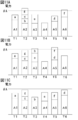
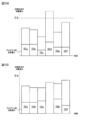
- FIG. 8A is a diagram illustrating a state before the shift of the defrost shift control
- FIG. 8B is a diagram illustrating a state after the shift.
- FIG. 9A is a bar graph showing a state before the shift of the defrost shift control
- FIG. 9B is a bar graph showing a state after the shift.
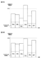
- FIG. 10A is a diagram illustrating a state before the shift of the defrost shift control
- FIG. 10B is a diagram illustrating a shift process
- FIG. 10C is a diagram illustrating a state after the shift.
- FIG. 11A is a bar graph showing the state before the shift of the defrost shift control
- FIG. 11B is a bar graph showing the shift process
- FIG. 11C is a bar graph showing the state after the shift.
- It is the schematic of the shop which concerns on Embodiment 2.
- FIG. It is a block diagram of the operation management apparatus which concerns on Embodiment 2.
- FIG. 2 It is a figure which shows an example of grouping based on the power consumption of the whole store which concerns on Embodiment 2.
- FIG. It is a figure which shows the 1st example of the time transition of the power consumption of the whole store which concerns on Embodiment 2.
- FIG. It is a figure which shows the 2nd example of the time transition of the power consumption of the whole shop which concerns on Embodiment 2.
- Refrigeration and freezing equipment for stores include showcases for refrigeration and freezing, refrigerators installed in kitchens and backyards, freezers, air conditioning equipment for stores, etc.
- showcases compressed outdoors or on the rooftop
- An outdoor unit having a machine and a condenser is arranged, and an indoor unit having an evaporator and a decompression device is arranged in the store.
- a plurality of indoor units are installed in this single outdoor unit so that a refrigeration cycle is formed in parallel with cooling pipes.
- many devices that consume power such as lighting and a heat cooker, are installed in the store.
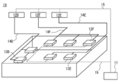
- the store 10 is a supermarket as an example, and seven refrigerators 12A to 12G (hereinafter, these refrigerators 12A to 12G need to be distinguished as outdoor units). In the case where there is not, it may be simply expressed as “refrigerator 12”), and a case where one to four cooling / heating devices 13 as indoor units connected to each refrigerator 12 are installed will be described.
- the showcases 13A to 13C and 13G and the air conditioners 13D to 13E installed in the store 10 as the cooling / heating device 13 will be described as an example.
- Each refrigerator 12 is connected to the operation management device 11 of the refrigerator through a signal line 15.
- the operation management device 11 manages, for example, the time at which a shift signal for night of the temperature set value for each of the showcases 13A to 13C and 13G and the air conditioners 13D to 13E is output, the operation start time for air conditioning, the temperature set value, For example, it outputs a switching signal for cooling or heating and manages the lighting time of lighting.
- the operation management device 11 manages a storage unit 16 in which various set times, power consumption, and the like are stored, a power consumption prediction unit 17 that predicts power consumption, a defrosting start time, and power consumption prediction. Based on the power consumption predicted by the unit 17, a defrosting shift control unit 18 that changes the defrosting start time, outputs a shift signal of the temperature setting value of the air conditioner, and the like is provided.
- Each refrigerator 12 and each cooling machine 13 and cooling pipes 14A to 14G (hereinafter, when there is no need to distinguish between these cooling pipes 14A to 14G, they may be simply expressed as “cooling pipe 14”). Connected with.
- the showcases 13A to 13C and 13G are connected to the four refrigerators 12A to 12C and 12G, and the air conditioners 13D to 13E are connected to the three refrigerators 12D to 12E. .
- the respective refrigerators 12, the showcases 13A to 13C and 13G, and the air conditioners 13D to 13E are managed by the operation management apparatus 11 via the signal lines 15, respectively.
- the configuration of the air conditioners 13D to 13F as the refrigeration equipment 13 includes three outdoor units 12D to 12F as the refrigerators 12D to 12E, and each of the outdoor units 12D to 12F has a refrigeration equipment.
- Two to three air conditioners 13D to 13F as 13 are connected by cooling pipes 14D to 14F.
- the outdoor units 12D to 12F and the air conditioners 13D to 13F are connected to the operation management apparatus 11 via signal lines 15, respectively, and their operations are managed.
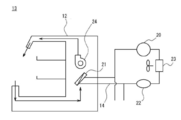
- the showcases 13A to 13C and 13G as the cooling / heating devices 13 are provided with an evaporator 21 inside, and the air cooled by the evaporator 21 is used for the showcases 13A to 13G using a fan 24.
- the products in the display cases 13A to 13C and 13G can be kept at a suitable temperature by circulating through the 13C and 13G.
- the evaporator 21 is provided for each of the showcases 13A to 13C and 13G, and includes the compressor 20, the condenser 23 and the decompression device 22, and the refrigerant pipes 14A to 14G formed in the refrigerators 12A to 12C and 12G, respectively.
- 14C and 14G are connected in an annular shape to constitute a refrigeration cycle.
- the cooling temperature varies depending on the products displayed in the showcases 13A to 13C and 13G.
- fresh fish and meat are -2 ° C to 2 ° C
- fruits and vegetables are 5 ° C to 10 ° C
- daily products dairy products
- It is about 3 ° C to 7 ° C for prepared dishes, and about -18 ° C to -22 ° C for frozen foods and ice creams.
- the showcases 13A to 13C and 13G have different power consumption due to the difference in cooling temperature.
- the refrigeration cycle will be described.
- the refrigeration cycle is provided in the compressor 20 and the condenser 23 provided in the refrigerator 12 respectively, and in the showcases 13A to 13C and 13G and the air conditioners 13D to 13F constituting the cooling / heating device 13, respectively.
- the reduced pressure device 22 and the evaporator 21 are configured.
- four evaporators 21, that is, four refrigeration devices 13 are connected to one compressor 20. Therefore, in the refrigeration cycle shown in FIG. 4, the compressor 20, the condenser 23, and the decompression device 22 are configured in common, and only for the showcases 13A to 13C and 13G constituting the cooling / heating device 13, that is, four sets of refrigerations. There will be a cycle.
- the compressor 20 of the refrigerator 12 when the compressor 20 of the refrigerator 12 is started, the high-temperature and high-pressure liquid refrigerant compressed by the compressor 20 is discharged from the compressor 20 and enters the condenser 23 to be cooled.
- the cooled refrigerant enters a gas-liquid mixed state and flows into each evaporator 21 via the decompression device 22.
- the decompression device 22 the refrigerant is decompressed and adiabatically expands to lower the temperature, and further evaporates in the evaporator 21 to take heat of vaporization from the surroundings, thereby cooling the inside of the cooling apparatus 13.
- the low-temperature and low-pressure refrigerant evaporated in the evaporator 21 is configured to be circulated to the compressor 20 of the refrigerator 12.
- the evaporator 21 provided in the cooling / heating device 13 will be described.
- the evaporator 21 is in a cooled state as described above. And if the air which circulates through the inside of the cooling-heat equipment 13 contacts this cooled evaporator 21, the water
- the cooling / heating device 13 it is necessary to remove frost adhering to the evaporator 21.
- the operation of removing the frost is performed by stopping the operation of the compressor 20 of the refrigerator 12 and stopping the cooling of the evaporator 21. At this time, by continuing the operation of the fan 24, the wind continues to hit the evaporator 21, and the defrosting efficiency can be increased. Further, by providing the evaporator 21 with a heater (not shown) as a heating means, the efficiency of defrosting can be further increased. After the defrosting is completed, the operation of the compressor 20 of the refrigerator 12 is started again.
- the temperature change of the refrigeration equipment 13 after the defrosting is completed and the power consumption of the compressor 20 of the refrigerator 12 will be described with reference to FIG.
- the operation of the refrigerator 12 is stopped (OFF) for defrosting, the power consumption of the refrigerator 12 is reduced, but the temperature of the refrigeration equipment 13 is increased.
- the stop time of the refrigerator 12 is 30 minutes.
- the operation of the compressor 20 of the refrigerator 12 is resumed (ON) in order to lower the elevated temperature in the refrigeration equipment 13. Since the operation of the refrigerator 12 at this time is performed with the maximum output (hereinafter referred to as “pull-down”), the power consumption is greatly increased.
- the temperature in the cooling / heating device 13 decreases and reaches around the set temperature, the temperature is controlled to be constant, and the power consumption is repeatedly increased and decreased in synchronization therewith. And this defrosting is repeatedly performed for every fixed time.
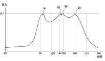
- FIG. 6 is a graph illustrating the transition of power consumption in a general supermarket.
- the first mountain M1 appears around 9 o'clock when the supermarket opens. This is due to the start of operation of various facilities for opening the store.
- the power consumption once falls, but a second peak M2 appears from 14:00 to 15:00. This is because from 14:00 to 15:00 is the time during which the air temperature is highest during the day, the operation of the refrigerator or the like becomes active in order to maintain the temperature of the product that requires cooling.
- the power consumption once again decreases, but the power consumption increases again around 18:00, and a third peak M3 appears. This is because visitors have become active and needed cooling.
- ⁇ A in this graph is the maximum power contracted with the electric power company. If this value is exceeded, the breaker may fall and cause a power failure.
- this graph is an example of a supermarket, the transition of power consumption is not limited to this, and the number of peaks may increase or decrease.
- the evaporator 21 provided in the showcase 13 requires defrosting, and after this defrosting is performed, a pull-down in which the power consumption of the refrigerator 12 suddenly increases for cooling always occurs.
- the power consumption increases more rapidly. Become.
- the graph in FIG. 4 is an example of power consumption and does not necessarily change according to this graph.
- the time may be off. Therefore, it is difficult to change the defrosting time one by one in correspondence with the daily power consumption. Therefore, in the operation management apparatus 11 of Embodiment 1, the defrosting shift control part 18 (refer FIG. 1) is managed to shift the defrosting start time.
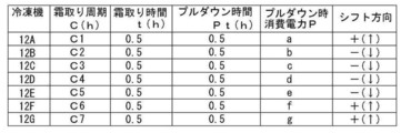
- the data shown in FIG. 7 is data related to the refrigerator 12 that is stored in advance in the storage unit 16 as data necessary for defrost shift control, and data related to power consumption of the supermarket 10.
- the data stored in the storage unit 16 at this time includes the defrosting cycle C, the defrosting time t, the pull-down time Pt, the power consumption P during pull-down, the shift direction, the past power consumption, and the past power consumption for each of the refrigerators 12A to 12G. Changes in temperature and weather.
- the cycle C of defrosting is data indicating how often each refrigerator 12 performs defrosting, and the cycle differs depending on the necessity of defrosting depending on the usage mode of the cooling / heating device 13 connected to each refrigerator 12. Approximately 3 to 5 hours.
- the defrosting time t is a time during defrosting, and in the first embodiment, the defrosting time t of all the refrigerators 12 is set to 30 minutes.
- the pull-down time Pt is a time for performing pull-down, and in the first embodiment, the pull-down time Pt for all the refrigerators is set to 30 minutes.
- the power consumption P at the time of pull-down is the amount of power consumed by the refrigerators 12A to 12G at the time of pull-down, and is different for each refrigerator 12A to 12G.
- the shift direction is determined by the priority of the refrigeration equipment, and the priority is determined by the type of the refrigeration equipment 13, in particular, the products displayed in the showcases 13A to 13C, 13G, as in the case of commodities such as raw products.
- Refrigeration and refrigeration products are shifted to the previous defrosting start time because items that require constant cooling are considered to be high priority. On the other hand, frozen products and refrigerated products are less likely to affect product quality even if cooling efficiency is suppressed.
- the defrosting start time is shifted later as a low degree.
- the cooling / heating device 13 is the air conditioning device 13D to 13F
- the priority is appropriately set and the shift direction is appropriately set in consideration of the power consumption and the air conditioning range of the individual air conditioning devices 13D to 13F.
- the predicted power consumption A is calculated in the power consumption prediction part 17.
- FIG. It is preferable that the predicted power consumption A at this time is corrected by the temperature and weather of the day because more detailed power consumption can be predicted. A method of calculating the predicted power consumption A will be described later.
- the power consumption stored at this time is, for example, a value obtained by graphing the power consumption and integrating the power consumption for 30 minutes.
- An average value of power consumption for a predetermined period of the stored power consumption, for example, 30 minutes at the same time in the past 10 days is obtained, and this value is set as predicted power consumption A.
- This prediction is performed for a predetermined time, for example, up to 3 hours ahead, and the predicted power consumption A is corrected and determined by changes in the temperature and weather of the day.
- This correction can also be performed using the data stored in the storage unit 16, and can be determined by the difference between the average temperature of the 10 days and the temperature of the day, or the difference in power consumption due to weather can be stored in advance, The average value of power consumption can be corrected. Further, if the power consumption, temperature and weather for the past year are stored in the storage unit 16 as data for determining the correction value at this time, a more detailed correction value can be derived and the power consumption can be accurately predicted. can do.
- the power consumption P at the time of pulling down each of the refrigerators 12A to 12G stored in the storage unit is added to the predicted power consumption A, and the total predicted power consumption AT at this time is the power company during the previous three hours. It is determined whether or not the amount of power ⁇ A determined by the contract with is exceeded.
- the refrigerator that shifts the defrosting start time is determined with reference to the shift priority (shift direction). This shift is performed based on the total predicted power consumption AT predicted by the power consumption prediction unit 17 up to three hours ahead, and further optimal air conditioning so that optimum operation is possible for the products in the showcase.
- the operation of the refrigerator 12 is appropriately shift controlled so that the control is performed.
- FIG. 8A shows the prediction of the refrigerator of the first embodiment up to 3 hours ahead.
- the predicted times T1 to T6 are the time from the next 30 minutes of the 30-minute section including the current time divided every 30 minutes.
- the predicted power consumption values A1 to A6 are derived from the average value of power consumption at the same time in the past 10 days, and indicate the power that will be consumed from now on every predicted time T1 to T6.
- the predicted power consumption value is corrected according to the temperature and weather of the day.
- the power consumption P at the time of pull-down indicates the power consumption when each refrigerator performs pull-down.
- the total predicted power consumption AT is obtained by adding the pull-down power consumption P (a to f) to the total predicted power consumption A1 to A6. Contract power excess is a judgment of whether the total predicted power consumption AT exceeds the amount of power ⁇ A contracted with the power company.
- the shift is performed based on the judgment whether this contract power is exceeded. That is, as shown in FIGS. 8A and 9A, since the total predicted power consumption exceeds the contract power at the predicted times T2 and T3, it is necessary to shift the defrosting start time in this time zone. Therefore, as shown in FIGS. 8B and 9B, at the time of the predicted time T2, it is necessary to shift the defrosting start time of any of the refrigerators 12B, 12C, and 12G.
- the shift direction of the refrigerators 12B and 12C is downward, and the refrigerator 12G is upward.
- the estimated shift time T3 of the refrigerators 12B and 12C exceeds the contract power, but the estimated shift time T1 of the refrigerator 12G does not exceed. Therefore, the defrosting start time of the refrigerator 12G is shifted to the predicted time T1.
- the shift direction of the refrigerator 12D at the predicted time T3 is upward, and the shift direction of the refrigerator 12E is downward.
- the refrigerator 12D is shifted to the predicted time T2
- the contract power is exceeded, so the refrigerator 12E is shifted to the predicted time T4.
- the total predicted power consumption AT up to 3 hours ahead does not exceed the contract power ⁇ A.
- FIG. 10A is the same as FIG. 8A, but the power consumed by the supermarket differs depending on the time zone to be predicted (see FIG. 6), so the predicted time exceeding the contracted power is different. That is, in the example shown in FIGS. 10A and 11A, the contract power ⁇ A is exceeded at the predicted times T2 and T6.
- the shift control at this time needs to shift the refrigerators 12B, 12C, and 12G of the predicted time T2 to any one, but when these are shifted, the total predicted consumption after the shift of the predicted times T1 and T3 of the shift destination All of the power exceeds the contract power.
- the refrigerator 12B is shifted downward.
- the defrosting start time of the refrigerator 12E is shifted to prediction time T4.
- the defrosting start time of the refrigerator 12C may be shifted.
- the defrosting start time of the refrigerator 12G is shifted, it is necessary to further shift the defrosting start time of the refrigerator 12a.
- the refrigerator which performs a shift can be selected suitably.
- the defrosting start time of the refrigerator 12D is shifted.
- the defrosting start times of the refrigerator 12D and the refrigerator 12F are respectively exchanged.
- the total predicted power consumption AT up to 3 hours ahead does not exceed the contract power ⁇ A.
- Embodiment 1 demonstrated the case where there were seven refrigerators, if a store area became large, many combinations of a plurality of outdoor units and indoor units were installed, and defrosting was set for each outdoor unit. Repeated every cycle. This period is set based on the capacity of the outdoor unit, the difference between freezing and refrigeration, the air conditioning capacity, and the like. Even in such a case, it is possible to suppress exceeding the contract power ⁇ A by repeating the shift of the defrosting start time as appropriate. In that case, it is also conceivable to shift the defrosting start time of the refrigerator by two or more of the predicted times. In that case, it may be set in the shift priority whether or not the shift is possible a plurality of times. In the first embodiment, the defrost shift control unit shifts the defrosting start time. However, the present invention is not limited to this, and the defrosting end time may be shifted.
- Embodiment 2 Next, Embodiment 2 will be described. While Embodiment 1 has suppressed power consumption predicted and predicted for power consumption for each refrigerator from exceeding contract power, Embodiment 2 has a plurality of units connected to each refrigerator. Based on various types of information about the refrigeration equipment, the refrigeration equipment connected to other refrigerators is grouped to reduce power consumption. In the second embodiment, there will be described a case where there are three refrigerators and three refrigerators are connected to each refrigerator.
- FIG. 12 is an overall schematic configuration diagram of a store 10A according to Embodiment 2 of the present invention.
- the operation management apparatus 11A shown in FIG. 12 is installed in a store 10A such as a supermarket.
- the store 10A includes an operation management apparatus 11A, refrigerators 12H to 12J (hereinafter sometimes collectively referred to as “refrigerator 12”), and showcases 13a to 13i as cooling and heating devices (hereinafter collectively referred to as “showcases”). 13 ”).
- the store 10 ⁇ / b> A is installed with devices that consume power, such as an indoor unit and an outdoor unit of an air conditioner (not shown), lighting, and a heating cooker.
- the operation management device 11 ⁇ / b> A, the refrigerator 12 and the showcase 13 are connected by a signal line 15.
- the operation management apparatus 11 ⁇ / b> A transmits a control signal to the refrigerator 12 and the showcase 13 via the signal line 15 and performs various controls such as defrosting of the showcase 13.
- the operation management device 11A manages the time when the nighttime shift signal of the temperature setting value for each indoor unit is output, the operation start time for air conditioning, the output of the temperature setting value, the switching signal for cooling or heating, and the lighting lighting time. In addition to managing the defrosting time (cycle), the power consumption of the entire store is detected, the defrosting time is changed, and the temperature setting value shift signal of the air conditioner is output.
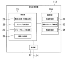
- FIG. 2 is a configuration diagram of the operation management apparatus 11A.
- the operation management apparatus 11A shown in FIG. 2 includes a control unit 25, a storage unit 16, and a communication unit 27.
- the control part 25 is comprised by CPU, for example, and controls the various functions with which the operation management apparatus 11A comprises.
- the controller 25 includes a defrost cycle / time calculator 28, a grouping processor 29, a group check processor 30, and a defrost controller 31.
- the storage unit 16 stores various information used for control and the like in the operation management apparatus 11A.
- the storage unit 16 includes a device information unit 32, a defrost group information unit 33, and a history information unit 34 as storage areas.
- the communication unit 27 is connected to the signal line 15 and transmits a control signal to the refrigerator 12 and the showcase 13 via the signal line 15 under the control of the control unit 25, or alternatively, the communication unit 27 is connected to the refrigerator 12 and the showcase 13. Various signals from the case 13 are received.
- the operation of the operation management apparatus 11A specifically, the operation of setting a plurality of groups (defrosting groups) that are a set of showcases having the same defrosting time and defrosting cycle when the defrosting of the showcase 13 is performed will be described. To do.
- the defrost cycle / time calculation unit 28 in the control unit 25 acquires the device information stored in the device information unit 32 in the storage unit 16.
- Device information is prepared for each showcase 13.
- This equipment information includes the ID of the corresponding showcase, the power consumption and set temperature at the time of pull-down, the ID of the refrigerator to which the corresponding showcase is connected, the temperature and humidity around the corresponding showcase, and the corresponding showcase Various kinds of information such as the contents (vegetables, fish, meat, etc.) and the installation location are included.
- the defrost cycle / time calculation unit 28 calculates the defrost cycle of each showcase 13 corresponding to the device information and the time required for one defrost (defrost time) based on the acquired device information. For example, the defrost cycle / time calculator 28 shortens the defrost cycle and lengthens the defrost cycle as the set temperature included in the device information is lower.
- the device information may include a defrosting cycle and a defrosting time for each showcase. In this case, the defrost cycle / time calculator 28 acquires the defrost cycle and defrost time of each showcase as they are.
- the grouping process part 29 in the control part 25 performs the grouping which puts together the showcases in which the corresponding defrosting periods and defrosting times match into one group.
- the grouping processing unit 29 does not combine only the showcases corresponding to the corresponding defrost cycle and defrost time into one group, but the corresponding defrost cycle is within a predetermined range, and the defrost time is within the predetermined range.
- the showcases that are within may be considered as the same defrost cycle and defrost time and may be grouped into one group.
- the grouping processing unit 29 After grouping based on the defrost cycle and the defrost time is performed, the grouping processing unit 29 associates the set ID of each group, the ID of the showcase belonging to the group, the defrost cycle and the defrost time. Generate defrost group information. Further, the grouping processing unit 29 stores the defrosting group information in the defrosting group information unit 33 in the storage unit 16.
- the group check processing unit 30 in the control unit 25 acquires, for each set group, the power consumption at the time of pulling down the showcase belonging to the group from the device information.
- the group check processing unit 30 calculates, for each group, the total power consumption when pulling down the showcases belonging to the group.
- the calculated total power consumption during pull-down is the total power consumption during pull-down of the showcase belonging to the corresponding group.
- the control unit 25 generates defrosting schedule information based on the defrosting period and defrosting time corresponding to each group so that the defrosting time zones corresponding to each group do not overlap.
- the group check processing unit 30 acquires a time zone (power consumption peak zone) in which the power consumption of the entire store is at a peak.
- the history information unit 34 in the storage unit 16 stores history information indicating the elapsed time of power consumption of the entire past store, and the group check processing unit 30 uses the power consumption peak band based on this history information. Can be specified.
- the group check processing unit 30 determines whether a pull-down occurs in the power consumption peak band based on the identified power consumption peak band and the defrost schedule information. In addition, pull-down is a return operation performed to cool again the inside of the showcase where the temperature has risen as the final stage of defrosting, and the power consumption is larger than that during normal operation.
- the group check processing unit 30 extracts the power consumption at the time of pull-down from the device information of each showcase belonging to the group where the pull-down occurs in the power consumption peak band. Further, the group check processing unit 30 calculates a total value (peak group power consumption) of the extracted pull-down power consumption.
- the group check processing unit 30 acquires the power consumption of the entire store in the power consumption peak zone based on the history information.
- the group check processing unit 30 acquires the power consumption of the entire store in the defrosting time zone before and after the power consumption peak zone based on the history information.
- the group check processing unit 30 causes all or part of the showcases belonging to the group in which the pull-down occurs in the power consumption peak band to belong to the group corresponding to both or one of the front and rear defrosting time bands.
- the group check processing unit 30 generates defrosting group information according to the change of the group to which the showcase belongs. Further, the group check processing unit 30 causes the defrost group information unit 33 to store the generated defrost group information. Then, after the defrost control for each group after the change is completed, the group configuration returns to the group configuration before the change.
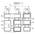
- FIG. 14 is a diagram illustrating an example of first grouping based on power consumption of the entire store.
- FIG. 15 is a diagram illustrating a first example of time transition of power consumption of the entire store.
- initial groups 35a to 35f are set. As shown in FIG. 15A, among the groups 35a to 35f, the group 35d has a pull-down in the power consumption peak band.
- the showcase 13h belonging to the group 35d belongs to the new group 36a having the same defrosting time zone as the group 35c together with the showcase 13g belonging to the group 35c.
- the showcase 13e belonging to the group 35d belongs to a new group 36b having the same defrosting time zone as the group 35e together with the showcase 13f belonging to the group 35e.
- the time transition of the power consumption of the entire store is as shown in FIG. 15B, and the power consumption of the entire store in the power consumption peak band becomes small, and the possibility of exceeding the contract power ( ⁇ A) can be suppressed.
- the control unit 25 generates defrosting schedule information based on the defrosting period and defrosting time corresponding to each group so that the defrosting time zones corresponding to each group do not overlap.
- the group check processing unit 30 acquires a time zone (power consumption peak zone) in which the power consumption of the entire store is at a peak.
- the history information unit 34 in the storage unit 16 stores history information indicating the elapsed time of power consumption of the entire past store, and the group check processing unit 30 uses the power consumption peak band based on this history information. Can be specified.
- the group check processing unit 30 extracts the power consumption at the time of pull-down from the device information of each showcase belonging to the group where the pull-down occurs in the power consumption peak band. Further, the group check processing unit 30 calculates a total value (peak group power consumption) of the extracted pull-down power consumption.
- the group check processing unit 30 acquires the power consumption of the entire store in the power consumption peak zone based on the history information.
- the group check processing unit 30 determines the total power consumption during pull-down of each showcase belonging to the group in which the pull-down occurs within a predetermined time before and after the power consumption peak band (group outside peak time) based on the history information. Power consumption).
- the group check processing unit 30 determines whether or not there is a non-peak group power consumption that is lower than the peak group power consumption.
- the group check processing unit 30 When there is a non-peak group power consumption that is lower than the peak group power consumption, the group check processing unit 30 performs a defrosting time zone corresponding to the group corresponding to the peak group power consumption, and a minimum non-peak time. Replace the defrosting time zone corresponding to the group corresponding to the group power consumption.
- the group check processing unit 30 generates defrosting group information in accordance with the replacement of the groups. Further, the group check processing unit 30 causes the defrost group information unit 33 to store the generated defrost group information. Then, after the defrosting control for each group after the change is completed, the group configuration returns to the group configuration before replacement.
- FIG. 16 is a diagram showing a second example of the time transition of power consumption of the entire store.
- the power consumption of the group 35c is smaller than the power consumption of the group 35d where the pull-down occurs in the power consumption peak band, and is the minimum.
- the defrosting time zone corresponding to the group 35c and the defrosting time zone corresponding to the group 35d are switched, and the power consumption of the entire store in the power consumption peak zone is reduced, and the contract power ⁇ A The risk of exceeding the limit can be suppressed.
- the defrost control unit 31 in the control unit 25 is based on the defrost group information stored in the defrost group information unit 33 in the storage unit 16 for each group.
- the defrosting control of the showcase belonging to the group is performed at different timings.
- 11 A of operation management apparatuses are grouped based on the power consumption of a showcase, grouping based on the connection state of a showcase and a refrigerator, grouping based on the total value of the defrosting time of each group, and All of the grouping based on the power consumption of the entire store was performed, but these can be selected as appropriate.
- the order of grouping can be changed as appropriate.
Landscapes
- Engineering & Computer Science (AREA)
- Physics & Mathematics (AREA)
- Mechanical Engineering (AREA)
- Thermal Sciences (AREA)
- General Engineering & Computer Science (AREA)
- Chemical & Material Sciences (AREA)
- Combustion & Propulsion (AREA)
- Defrosting Systems (AREA)
- Air Conditioning Control Device (AREA)
Abstract
【課題】店舗に設置される複数の冷凍サイクルを備える冷熱機器の霜取りの開始時間を制御して、契約電力の最大値を超えないように制御すること。 【解決手段】圧縮機、凝縮器、減圧装置、蒸発器を用いた冷凍サイクルが構成された冷熱機器が単一の店舗内に複数設置され、複数の冷凍サイクル毎の蒸発器の除霜を制御する冷凍機の運転管理装置において、複数の冷凍サイクル毎の除霜開始時刻又は除霜終了時刻、除霜終了後の冷熱機器のプルダウンに要する消費電力と、店舗の少なくとも複数の冷凍サイクルの消費電力を含む所定時刻毎の予測された消費電力とから、プルダウンが行われる際の合計予測消費電力を求め、この合計予測電力が店舗により予め設定されている消費電力の上限値θAを超えないように適宜冷熱機器の除霜開始時刻又は除霜終了時刻を変更する。
Description
本発明は、冷凍機の運転管理装置に関し、詳しくは、スーパーマーケット等の店舗に設置される複数のショーケース、冷蔵庫、冷凍庫及び空調機器などの冷凍サイクルを備える冷熱機器の霜取り時間を制御して所定の最大電力を越えないようにする冷凍機の運転管理装置に関する。
スーパーマーケット等の店舗では、店舗内に設置されたショーケースや空調機器等の冷凍サイクルを有する複数の冷熱機器の運転状態を、冷凍機の運転管理装置によって一括制御している。冷凍サイクルは、一般に圧縮機、凝縮器、減圧装置及び蒸発器を環状に接続したサイクルであり、冷却運転を行う際に蒸発器に着霜が生じると、その熱伝導性の低さから冷却効率が低下してしまう。空調機器の場合、冷房運転時は、蒸発器の温度が15℃前後で使用されるため、冷蔵装置や冷凍装置に比べて温度が高く、着霜が生じること少ない。しかしながら、暖房運転時には、蒸発器の温度が0℃以下で用いられることがあるので、着霜が生じる。
従来、複数の冷熱機器の霜取りに際して、当該複数の冷熱機器をグループ化し、グループ毎に霜取りのタイミング制御を行っている(例えば、特許文献1参照)。このように冷熱機器のグループ化がなされることによって、グループ毎に霜取り時間や霜取り周期を設定すればよく、各冷熱機器毎に設定する場合と比較して手間を省くことができる。
しかしながら、上記特許文献1に開示された霜取り制御では、霜取り後にショーケース内を再度冷却するための復帰(プルダウン)時の冷熱機器の消費電力については考慮されておらず、例えば、電力会社により消費電力の上限値が設定されている店舗の場合は、このプルダウンによる消費電力の増加と店舗の営業により消費電力の増加とが一致すると消費電力が設定した上限値を越えてしまう可能性がある。
そこで、本発明は、冷熱機器のプルダウン時の消費電力の増加を考慮した霜取り制御を実現するための冷熱機器の運転制御を可能にし、所定の最大電力を越えないようにする冷凍機の運転制御装置を提供するものである。
上述した課題を解決するために、本発明は以下のような特徴を有している。まず、本発明の冷凍機の運転管理装置は、少なくとも圧縮機、凝縮器、減圧装置、蒸発器を用いた冷凍サイクルが構成され、前記蒸発器で冷媒が蒸発する際の吸熱作用を利用して被冷却物の冷却を可能に構成した冷熱機器が単一の店舗内に複数設置され、前記複数の冷凍サイクル毎の前記蒸発器の除霜を制御する冷凍機の運転管理装置において、冷凍機の運転管理装置は、さらに、前記複数の冷凍サイクル毎の除霜開始時刻又は除霜終了時刻、除霜終了後の前記冷熱機器のプルダウンに要する消費電力が記憶される記憶部と、前記店舗の少なくとも前記複数の冷凍サイクルの消費電力を含む所定時刻毎の消費電力を予測する消費電力予測部と、前記プルダウンが行われる際に、前記消費電力予測部により予測された消費電力に前記記憶部に記憶された前記プルダウン時の消費電力を加えた合計予測消費電力が、前記店舗により予め設定されている消費電力の上限値を超えないように前記除霜開始時刻又は前記除霜終了時刻を変更する除霜シフト制御部と、を備えることを特徴とする。
本発明の冷凍機の運転管理装置によれば、複数の冷凍サイクル毎の霜取りの開始時刻又は終了時刻の制御を行うことで、店舗の営業により消費される予測された消費電力に対して霜取り後のプルダウン時の消費電力の増加を考慮した冷凍機の運転を行うことができるため、電力会社により消費電力の上限値が設定されている店舗の場合は、店舗の消費電力とプルダウンよる消費電力との和が予め設定された上限値を越えてしまうことを抑制することができる。この場合において、一部の冷凍サイクルにおける消費電力は予測に使用しなくてもよい。
また、本発明の冷凍機の運転管理装置においては、前記除霜シフト制御部は、前記合計予測消費電力が前記店舗により予め設定されている消費電力の上限値を越える場合に、前記複数の冷凍サイクルのうちの1つの冷凍サイクルの前記除霜開始時刻又は除霜終了時刻と別の前記冷凍サイクルの前記除霜開始時刻又は前記除霜終了時刻とを入れ替えることが好ましい。
複数の冷凍サイクルは、設置される機器や、使用される態様によりそれぞれ消費電力が異なる。本発明の冷凍機の運転管理装置によれば、合計予測消費電力が前記店舗により予め設定されている消費電力の上限値を越える場合であっても、消費電力の異なる複数の冷凍サイクル間の霜取り開始時刻又は終了時刻を入れ替えることで、実際の店舗の営業により消費される消費電力とプルダウンよる消費電力との和が予め設定された上限値を越えてしまうことを抑制することができる。
また、本発明の冷凍機の運転管理装置においては、前記記憶部は、更に前記店舗の一日分の消費電力を24時間を30分毎の区分に分け、前記30分毎の消費電力の積分値を過去の消費電力として記憶していることが好ましい。
本発明の冷凍機の運転管理装置によれば、記憶部に記憶されている過去の30分毎に区切られた消費電力に基いて合計予測消費電力を予測することができるので、より詳細な合計予測消費電力の予測ができるようになる。
また、本発明の冷凍機の運転管理装置においては、前記記憶部は、前記店舗の室温又は外気温並びに前記室温又は外気温の変化に対応した所定時刻毎の消費電力を記憶しており、前記消費電力予測部は、測定された前記店舗の室温又は外気温並びに前記室温又は外気温の変化と前記記憶部に記憶されている前記店舗の室温又は外気温並びに前記室温又は外気温の変化に対応した所定時刻毎の消費電力に基づいて、前記所定時刻毎の合計予測消費電力を予測することが好ましい。
本発明の冷凍機の運転管理装置によれば、測定された店舗の室温又は外気温並びに室温又は外気温の変化との関係を考慮して合計予測消費電力を予測することができるので、より正確な合計予測消費電力の予測が可能となる。
また、本発明の冷凍機の運転管理装置においては、前記記憶部は、天候及び前記天候の変化に対応した所定時刻毎の消費電力を記憶しており、前記消費電力予測部は、測定された天候及び前記天候の変化と前記記憶部に記憶された前記天候又は前記天候の変化に対応した所定時刻毎の消費電力を基に、前記所定時刻毎の合計予測消費電力を予測することが好ましい。
本発明の冷凍機の運転管理装置によれば、測定された天候及び天候の変化と記憶部に記憶されている天候及び前記天候の変化との関係を考慮して消費電力を予測することができるので、より正確な消費電力の予測が可能となる。
また、本発明の冷凍機の運転管理装置においては、前記記憶部は、最も新しく前記合計予測消費電力が予測されたときを基準として、過去1年間の所定時刻毎の消費電力が記憶されていることが好ましい。
本発明の冷凍機の運転管理装置によれば、過去1年間分の消費電力のデータと照らし合わせる参照することができるので、消費電力の予測がより正確になる。
また、本発明の冷凍機の運転管理装置においては、前記消費電力予測部は、最も新しく前記消費電力が予測されたときを基準として、前記記憶部の少なくとも過去10日間の所定時刻毎の消費電力の記憶の平均値を参照して前記所定時刻毎の合計予測消費電力を予測することが好ましい。
本発明の冷凍機の運転管理装置によれば、過去10日間の消費電力の平均値を用いて合計予測消費電力を予測することで、より正確に消費電力の予測を行うことができる。
また、本発明の冷凍機の運転管理装置においては、前記消費電力予測部は、最も新しく前記消費電力が予測されたときを基準として、少なくとも3時間先の前記所定時刻毎の合計予測消費電力を予測することが好ましい。
本発明の冷凍機の運転管理装置によれば、少なくとも3時間先まで合計予測消費電力を予測するので、消費電力変化の傾向が分かりやすく、霜取り開始時刻又は終了時刻のシフトを行いやすくなる。
また、本発明の冷凍機の運転管理装置においては、前記消費電力予測部による前記合計予測消費電力の予測は、最も新しく前記合計予測消費電力が予測されたときを基準として1時間毎に行われることが好ましい。
本発明の冷凍機の運転管理装置によれば、合計予測消費電力の予測を1時間毎に行うので、急な気温の変化や天気の変化による合計予測消費電力の補正が可能となり、より正確な消費電力の予測が可能となる。
また、本発明の冷凍機の運転管理装置においては、前記除霜シフト制御部は、前記冷熱機器の機器情報を取得し、前記冷熱機器の機器情報に基づいて、対応する前記冷熱機器の霜取り時間及び霜取り周期を算出する算出部と、前記算出部により算出された前記霜取り時間及び霜取り周期に基づいて、前記霜取り時間及び霜取り周期が一致する前記冷熱機器の集合であるグループを複数設定するグループ設定部と、前記グループ設定部によって設定された前記グループに関する少なくとも消費電力を含むグループ情報を記憶するグループ情報記憶部と、前記グループ情報記憶部に記憶された前記グループ情報に含まれる消費電力に基づいて、前記グループ毎に、順番を決定して前記グループに属する冷熱機器の霜取り制御を行う霜取り制御部とを備えていることが好ましい。
本発明の冷凍機の運転管理装置では、運転管理装置は、複数の冷熱機器の霜取り時間及び霜取り周期を算出し、当該霜取り時間及び霜取り周期に基づいて、霜取り時間及び霜取り周期が一致する冷熱機器の集合であるグループを複数設定する。更に、運転管理装置は、設定したグループに関する情報である霜取りグループ情報を記憶する。本発明の冷凍機の運転管理装置によれば、このようなグループ設定の結果、霜取りグループ情報に基づいて、複数のグループ毎に、異なるタイミングで当該グループに属する冷熱機器の霜取りがなされることで、プルダウン時の冷熱機器の消費電力が過大となり、更には、店舗全体の消費電力が上限値を超えてしまうことを防止することが可能となる。
また、本発明の冷凍機の運転管理装置においては、前記除霜シフト制御部は、前記グループのうち、一のグループに属する前記冷熱機器のプルダウン時の消費電力の合計値が前記店舗により予め設定されている消費電力の上限値以上である場合に、前記一のグループを分割して新たなグループを設定する第1のグループ再設定部を備えることが好ましい。
本発明の冷凍機の運転管理装置によれば、運転管理装置は、グループ設定によって設定された所定のグループに属する冷熱機器のプルダウン時の消費電力の合計値が閾値以上である場合に、当該所定のグループを分割して新たなグループを設定している。このため、プルダウン時の冷熱機器の消費電力が過大となることが防止され、更には、店舗全体の消費電力が上限値を超えてしまうことを防止することが可能となる。
また、本発明の冷凍機の運転管理装置においては、前記除霜シフト制御部は、1つの冷凍機冷却装置に冷却配管を介して接続されている全ての冷熱機器が一のグループのみに属する場合に、前記一のグループを分割して新たなグループを設定する第2のグループ再設定部を備えることが好ましい。
本発明の冷凍機の運転管理装置によれば、運転管理装置は、1つの冷凍機に冷却配管を介して接続されている全ての冷熱機器が所定のグループにのみ属する場合には、当該所定のグループを分割して新たなグループを設定している。このため、1つの冷凍機に接続された全ての冷熱機器が同時にプルダウンとなって、冷熱機器の消費電力が過大となることが防止され、更には、店舗全体の消費電力が上限値を超えてしまうことを防止することが可能となる。
また、本発明の冷凍機の運転管理装置においては、前記除霜シフト制御部は、予め定められた時間内に全ての前記冷熱機器の霜取りが完了しない場合に、前記グループのうち、2つ以上の前記グループを結合して新たなグループを設定する第3のグループ再設定部を備えることが好ましい。
本発明の冷凍機の運転管理装置によれば、運転管理装置は、各グループに対応する霜取り周期のうち、最小の霜取り周期の時間内に、全ての冷熱機器の霜取りが完了しない場合には、2つ以上のグループを結合して新たなグループを設定している。このため、複数のグループに属する冷熱機器が同時にプルダウンとなって、冷熱機器の消費電力が過大となることが防止され、更には、店舗全体の消費電力が上限値を超えてしまうことを防止することが可能となる。
また、本発明の冷凍機の運転管理装置においては、前記除霜シフト制御部は、前記冷熱機器が設置された店舗における、前記冷熱機器以外の機器の消費電力と前記冷熱機器の消費電力との合計が最大となるタイミングに対応する前記グループに属する前記冷熱機器の少なくとも一部を他のグループに所属させること、及び、前記冷熱機器が設置された店舗における、前記冷熱機器以外の機器の消費電力と前記冷熱機器の消費電力との合計が最大となるタイミングに対応する前記グループの前記タイミングと、他のグループに対応する前記タイミングとを入れ替えることの少なくとも何れかを行う第4のグループ再設定部を備えることが好ましい。
本発明の冷凍機の運転管理装置によれば、運転管理装置は、店舗全体の消費電力がピークとなる時間帯に、プルダウンが発生する冷熱機器が属するグループが存在する場合には、当該グループに属する冷熱機器の少なくとも一部を他のグループに所属させること、及び、店舗全体の消費電力がピークとなる時間帯にプルダウンが発生する冷熱機器が属するグループに対応する霜取りの時間帯と、他のグループに対応する霜取りの時間帯とを入れ替えることの何れかを行っている。このため、店舗全体の消費電力のピークを下げることが可能となる。
以下、本発明を実施するための形態について、実施形態及び図面を参照しながら詳細に説明する。ただし、以下に示す実施形態は、本発明の技術思想を具体化するための冷凍機の運転管理装置の一例を説明するものであって、本発明をこの実施形態に記載された冷凍機の運転管理装置に特定することを意図するものではなく、本発明は特許請求の範囲に含まれるその他の実施形態のものにも等しく適応し得るものである。
[実施形態1]
店舗用の冷熱機器には、冷蔵及び冷凍用のショーケース、厨房やバックヤードに設置される冷蔵庫、冷凍庫及び店舗用の空調機器などがあり、例えば、ショーケースの例では、屋外又は屋上に圧縮機及び凝縮器を有する屋外ユニットを配置し、店内に蒸発器及び減圧装置を有した室内ユニットが配置されている。通常は、この単一の屋外ユニットに複数の室内ユニットが冷却配管で並列に冷凍サイクルが構成されるように設置されている。また、店舗には、図示省略したが、照明及び温熱調理器等の電力を消費する機器も多く設置されている。
店舗用の冷熱機器には、冷蔵及び冷凍用のショーケース、厨房やバックヤードに設置される冷蔵庫、冷凍庫及び店舗用の空調機器などがあり、例えば、ショーケースの例では、屋外又は屋上に圧縮機及び凝縮器を有する屋外ユニットを配置し、店内に蒸発器及び減圧装置を有した室内ユニットが配置されている。通常は、この単一の屋外ユニットに複数の室内ユニットが冷却配管で並列に冷凍サイクルが構成されるように設置されている。また、店舗には、図示省略したが、照明及び温熱調理器等の電力を消費する機器も多く設置されている。
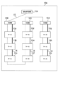
なお、実施形態1では、図1に示すように、店舗10としてスーパーマーケットの場合を例とし、屋外ユニットとして7台の冷凍機12A~12G(以下、これらの冷凍機12A~12Gを区別する必要がない場合には単に「冷凍機12」と表すことがある。)と、各冷凍機12に接続される屋内ユニットとしての冷熱機器13がそれぞれ1台から4台設置された場合について説明する。なお、本実施形態1では冷熱機器13として店舗10に設置されるショーケース13A~13C、13G及び空調機器13D~13Eを例に取り説明する。
また、各冷凍機12は、冷凍機の運転管理装置11と信号線15で接続されている。運転管理装置11は、例えば、各ショーケース13A~13C、13G及び空調機器13D~13Eに対する温度設定値の夜間用のシフト信号を出す時刻の管理や、空調用の運転開始時刻、温度設定値、冷房又は暖房の切り替え信号の出力、照明の点灯時刻の管理などを行う。さらに、運転管理装置11には、種々の設定時刻や消費電力等が記憶される記憶部16と、消費電力を予測する消費電力予測部17と、霜取り開始時刻の管理を行うと共に、消費電力予測部17により予測された消費電力を基に、霜取り開始時刻の変更や空調機器の温度設定値のシフト信号の出力等を行う除霜シフト制御部18が備えられている。
そして、各冷凍機12はそれぞれの冷熱機13と冷却配管14A~14G(以下、これらの冷却配管14A~14Gを区別する必要がない場合には単に「冷却配管14」と表すことがある。)で接続されている。なお、実施形態1では、4台の冷凍機12A~12C、12Gにはショーケース13A~13C、13Gが接続され、3台の冷凍機12D~12Eには空調機器13D~13Eが接続されている。このようにして、それぞれの冷凍機12及びショーケース13A~13C、13G及び空調機器13D~13Eが、それぞれ信号線15を介して運転管理装置11により管理されることになる。
冷熱機器13としての空調機器13D~13Fの構成は、図2に示すように、3台の冷凍機12D~12Eとしての室外機12D~12Fが設置され、それぞれの室外機12D~12Fに冷熱機器13としての空調機器13D~13Fが2~3台ずつ冷却配管14D~14Fにより接続されている。そして、この室外機12D~12F及び空調機器13D~13Fはそれぞれ信号線15を介して運転管理装置11に接続され、それぞれの運転が管理されている。
冷熱機器13としてのショーケース13A~13C、13Gは、図3に示すように、内部に蒸発器21が備えられ、この蒸発器21により冷やされた空気をファン24を利用してショーケース13A~13C、13G内を循環させ、ショーケース13A~13C、13Gに陳列された生鮮品や冷凍食品等の商品を適温にさせておくことができる。そして、この蒸発器21は、それぞれのショーケース13A~13C、13G毎に設けられ、冷凍機12A~12C、12Gにそれぞれ形成された圧縮機20、凝縮器23及び減圧装置22と冷媒配管14A~14C、14Gによって環状に接続され、冷凍サイクルを構成している。なお、ショーケース13A~13C、13Gに陳列される商品によって冷却される温度が異なり、例えば、鮮魚・精肉では-2℃~2℃、青果では5℃~10℃、日配品・乳製品・惣菜では3℃~7℃、冷凍食品・アイスクリームでは-18℃~-22℃程度である。また、各ショーケース13A~13C、13Gは、この冷却温度の違いにより消費される電力に差異が生じる。
ここで、冷凍サイクルについて説明する。冷凍サイクルは、図4に示すように、冷凍機12にそれぞれ備えられた圧縮機20及び凝縮器23と、冷熱機器13を構成するショーケース13A~13C、13G及び空調機器13D~13Fにそれぞれ備えられた減圧装置22及び蒸発器21とで構成される。なお、図4に示した冷凍サイクルでは、1つの圧縮機20に4つの蒸発器21、すなわち、4台の冷熱機器13が接続されていることになる。そのため、図4に示した冷凍サイクルでは、圧縮機20、凝縮器23及び減圧装置22を共通の構成とし、冷熱機器13を構成するショーケース13A~13C、13G分だけ、すなわち、4組みの冷凍サイクルが存在することになる。
この冷凍サイクルは、冷凍機12の圧縮機20が起動されると、圧縮機20で圧縮された高温高圧の液体の冷媒が圧縮機20から吐出され、凝縮器23に入って冷却される。冷却された冷媒は気液混合状態となり、減圧装置22を介してそれぞれの蒸発器21に流入する。減圧装置22において、冷媒は減圧されて断熱膨張することにより温度が低下し、更に蒸発器21において蒸発することで周囲から気化熱を奪い、冷熱機器13の内部の冷却を行う。この蒸発器21において気化した低温低圧の冷媒は冷凍機12の圧縮機20に循環されるように構成されている。
次に、冷熱機器13に備えられた蒸発器21について説明する。蒸発器21は、上述したように、冷却された状態となっている。そして、冷熱機器13内を循環する空気がこの冷却された蒸発器21に接すると、空気中の水分が蒸発器21の表面に凝縮して霜が付着する。霜は熱伝導率が低いため、霜が蒸発器21に付着したまま運転を続けると、冷却の効率が悪化する。
そのため、冷熱機器13においては、蒸発器21に付着した霜を取り除く作業が必要となる。この霜を取り除く作業は、冷凍機12の圧縮機20の運転を停止して蒸発器21の冷却を止めることで行われる。このときファン24の運転を続けることで、蒸発器21に風が当たり続けることになり、霜取りの効率を上げることができる。また、蒸発器21に加熱手段としてのヒーター(図示省略)を設けることで、さらに霜取りの効率をあげることができる。霜取りが完了した後、再度冷凍機12の圧縮機20の運転を開始する。
ここで、霜取りが完了した後の冷熱機器13の温度変化及び冷凍機12の圧縮機20の消費電力について図5を参照して説明する。霜取りのため冷凍機12の運転を停止(OFF)させると、冷凍機12の消費電力は低下するが、冷熱機器13の温度は上昇する。この冷凍機12の停止時間は30分としている。そして、霜取りが完了した後、冷熱機器13内の上昇した温度を下げるため、冷凍機12の圧縮機20の運転が再開(ON)される。このときの冷凍機12の運転は最大の出力で行われる(以下、「プルダウン」という)ため、消費電力は大幅に増大することとなる。その後、冷熱機器13内の温度が下がり、設定された温度近辺に達すると、温度を一定に保つように制御がされ、それに同調して消費電力も上昇及び下降を繰り返すことになる。そして、この霜取りは、一定時間ごとに繰り返し行われる。
次に、店舗としてのスーパーマーケット10全体の消費電力について図6を参照して説明する。図6は、一般的なスーパーマーケットの消費電力の推移を例示したグラフである。このグラフでは、スーパーマーケットが開店する9時を過ぎたあたりで1回目の山M1が現れる。これは、開店に向け各種設備の運転を開始したことに伴うものである。その後、消費電力は一旦下降するが、14時~15時にかけて2回目の山M2が現れる。これは、14時~15時が日中で最も気温が高くなる時間であるので、冷却を必要とする商品の温度を保つため冷凍機等の運転が活発になるためである。その後、また一旦消費電力は下降するが、18時頃に消費電力は再度上昇し3回目の山M3が現れる。これは、来客の出入りが活発になり、冷却を必要としたためである。そして、その後は閉店(21時)に向けて消費電力は下降することとなる。なお、このグラフにおけるθAは、電力会社と契約した最大電力であり、この値を超過すると、ブレーカーが落ちて停電するおそれがある。なお、このグラフはスーパーマーケットの一例であるので、消費電力の推移はこれに限られず、山の数も増減する場合がある。
次に、冷凍機12の消費電力とスーパーマーケット10の消費電力との関係を図5及び図6を参照して説明する。上述したように、ショーケース13に備えられた蒸発器21は霜取りを必要とし、この霜取りが行われた後には必ず冷却のため冷凍機12の消費電力が急激に上昇するプルダウンが発生する。このとき、実施形態1の場合では、冷凍機12は7台設置されているので、この7台のうち複数台が同時間帯にプルダウンを行うと、その消費電力はさらに急激に上昇することとなる。
一方、スーパーマーケット10においても、図6に示したように消費電力の波があり、この消費電力の山(M1~M3)のときと、冷凍機12のプルダウンが重なると、スーパーマーケット全体の消費電力が急激に高くなり、図6のM0のように電力会社と契約している電力量を超えてしまうことがある。
なお、あらかじめ霜取りの時刻を消費電力の山の時間からずらすことも考えられるが、図4のグラフは消費電力の一例であり、必ずしもこのグラフ通りに推移することはなく、気温や来客数により山の時間がずれることがある。したがって、毎日の消費電力に対応して、霜取りの時刻を逐一変更させることは困難である。そのため、実施形態1の運転管理装置11では、除霜シフト制御部18(図1参照)により、霜取りの開始時刻をシフトする管理を行うようにしている。
まず、霜取りの開始時刻のシフト制御に必要なデータについて説明する。図7に示したデータは、あらかじめ、除霜シフト制御に必要なデータとして記憶部16に記憶させておく冷凍機12に関するデータと、スーパーマーケット10の消費電力等に関するデータである。このときの記憶部16に記憶されるデータは、冷凍機12A~12Gごとの霜取りの周期C、霜取り時間t、プルダウン時間Pt、プルダウン時の消費電力P、シフト方向、過去の消費電力及び過去の気温及び天気の変化等である。
以下、実施形態1にかかる各冷凍機のデータの具体例を示す。実施形態1では、冷凍機12は7台設置されているため、この7台の冷凍機12A~12Gのデータを記憶させている。霜取りの周期Cは、各冷凍機12が霜取りをどのくらいの周期で行うかのデータであり、各冷凍機12に接続された冷熱機器13の使用形態により、霜取りの必要性によりその周期が異なり、概ね約3時間~5時間としている。霜取り時間tは霜取りを行っている間の時間であり、実施形態1では全ての冷凍機12の霜取り時間tを30分と設定している。プルダウン時間Ptはプルダウンを行う時間であり、実施形態1では全ての冷凍機のプルダウン時間Ptを30分と設定している。
プルダウン時の消費電力Pは、冷凍機12A~12Gがプルダウン時に消費する電力量であり、各冷凍機12A~12Gにより異なる。シフト方向は、冷熱機器の優先度によって決定され、その優先度は冷熱機器13の種類、特にショーケース13A~13C、13Gに陳列された商品により決定され、生もの等の商品の場合のように冷却が常に必要なものは優先度の高いものとして霜取り開始時刻を前にシフトし、一方、冷凍商品や冷蔵商品等は冷却の効率が抑えられても商品の品質に影響が出難いため、優先度の低いものとして霜取り開始時刻を後にシフトする。なお、冷熱機器13が空調機器13D~13Fの場合も、個々の空調機器13D~13Fの消費電力や空調範囲も考慮の上で、適宜優先度が設定され、シフト方向が適宜設定される。
そして、これらの記憶部16に記憶されたデータを基に、消費電力予測部17において予測消費電力Aを算出する。このときの予測消費電力Aは、当日の気温や天気により補正されるようにすると、より詳細な消費電力を予測することができるので好ましい。なお、予測消費電力Aの算出方は後述する。
次に、霜取り開始時刻のシフトについて説明する。まず、消費電力予測部17による消費電力の予測について説明する。予測の前提として、一日24時間を30分毎で1つの単位として区切り、この30分毎の過去の消費電力を記憶部16に記憶させる。このとき記憶される消費電力は、例えば、消費電力をグラフ化し、その消費電力を30分間積分した値である。この記憶させた消費電力の一定の期間、例えば過去10日間の同時刻の30分間の消費電力の平均値を求め、その値を予測消費電力Aとする。この予測は、一定の時間、例えば3時間先まで行われ、予測消費電力Aは、当日の気温や天候の変化により補正されて決定される。この補正も、記憶部16に記憶されたデータを用いて行うことができ、10日間の気温の平均値と当日の気温との差異で判断したり、天気による消費電力の違いをあらかじめ記憶させ、消費電力の平均値を補正することができる。また、このときの補正値を決めるデータとして、過去1年間の消費電力、気温及び天気を記憶部16に記憶させておくと、さらに詳細な補正値を導くことができ、消費電力を正確に予測することができる。
そして、この予測消費電力Aに記憶部に記憶された各冷凍機12A~12Gのプルダウン時の消費電力Pを加え、この時の合計予測消費電力ATが、先の3時間の間に、電力会社との契約により定められた電力量θAを超えるか否かを判断する。そして、合計予測消費電力ATが契約した電力量θAを超えているとされた場合、霜取りの開始時刻をシフトする冷凍機をシフト優先度(シフト方向)を参照して決定する。そして、このシフトは、消費電力予測部17が3時間先まで予測した合計予測消費電力ATに基いて行われ、ショーケース内の商品にとって最適な運転が可能となるように、更には最適な空調制御が行われるように、適宜冷凍機12の運転がシフト制御されることとなる。
次に、このシフト制御について図8~図11を参照して具体的に説明する。図8Aには、実施形態1の冷凍機の3時間先までの予測が示されている。予測時間T1~T6は、30分毎に区切られた時間の現在が含まれる30分の区分の次の30分からの時間である。消費電力予測値A1~A6は、過去10日間の同時刻における消費電力の平均値から導かれた、これから消費されるであろう電力を予測時間T1~T6毎に示したものである。なお、この消費電力予測値は、当日の気温及び天気等により補正が加えられている。プルダウン時消費電力Pは、各冷凍機がプルダウンを行ったときの消費電力を示したものである。合計予測消費電力ATは、合計予測消費電力A1~A6にプルダウン時消費電力P(a~f)を加えたものである。契約電力超過は、合計予測消費電力ATが、電力会社と契約した電力量θAを超過しているかを判断したものである。
この契約電力を超過しているかの判断を基に、シフトが行われる。すなわち、図8A及び図9Aに示すように、予測時間のT2及びT3において、合計予測消費電力が契約電力を超過しているので、この時間帯の霜取り開始時刻をシフトする必要がある。そこで、図8B及び図9Bに示すように、まず予測時間T2の時には、冷凍機12B、12C及び12Gのいずれかの霜取り開始時刻をシフトする必要がある。ここで、シフト優先度を見ると、冷凍機12B及び12Cのシフト方向は下方向であり、冷凍機12Gは上方向である。このとき、冷凍機12B及び12Cのシフト先の予測時間T3は契約電力を超過しているが、冷凍機12Gのシフト先の予測時間T1は超過していない。そこで、冷凍機12Gの霜取り開始時刻を予測時間T1へシフトする。
同様に、予測時間T3の冷凍機12Dのシフト方向は上方向であり、冷凍機12Eのシフト方向は下方向である。ここで、予測時間T2に冷凍機12Dをシフトさせると、契約電力を超過するので、冷凍機12Eを予測時間T4へシフトさせる。以上より、3時間先までの合計予測消費電力ATは、契約電力θAを超過することがなくなる。
次に、他の具体例を図10及び図11を参照して説明する。図10Aは図8Aと同じであるが、予測する時刻帯によりスーパーマーケットが消費する電力が異なるため(図6参照)、契約電力を超過している予測時間が異なっている。すなわち、図10A及び図11Aに示した例では、予測時間T2及びT6で契約電力θAを超過している。
このときのシフト制御は、予測時間T2の冷凍機12B、12C及び12Gをいずれかにシフトする必要があるが、これらをシフトした場合、シフト先の予測時間T1及びT3のシフト後の合計予測消費電力がいずれも契約電力を超過してしまう。このようなときは、まず冷凍機12Bを下方向にシフトする。そして、予測時間T3の合計予測消費電力が契約電力を超過するので、冷凍機12Eの霜取り開始時刻を予測時間T4へシフトする。このようにすることで、各冷凍機の霜取り開始時刻のシフトを最小限にすることができる。なお、このとき冷凍機12Cの霜取り開始時刻をシフトさせてもよい。しかし、冷凍機12Gの霜取り開始時刻をシフトさせると、冷凍機12aの霜取り開始時刻をさらにシフトさせる必要がでてくるので効率が悪くなり好ましくない。このように、シフトを行う冷凍機を適宜選択することができる。
次に、予測時間T6の場合、冷凍機12Fのシフト先は上方向であるので、予測時間T5へとシフトする。このとき、予測時間T5の合計予測消費電力が、冷凍機12Fのシフトのより契約電力を超過するので、冷凍機12Dの霜取り開始時刻をシフトさせる。このとき、冷凍機12Dのシフト方向は下方向であるので、冷凍機12Dの霜取り開始時刻を予測時間T6へとシフトさせる。すなわち、この場合、冷凍機12Dと冷凍機12Fの霜取り開始時刻をそれぞれ交換したこととなる。以上より、3時間先までの合計予測消費電力ATは、契約電力θAを超過することがなくなる。
なお、実施形態1では、冷凍機が7台の場合で説明したが、店舗面積が広くなれば、複数の屋外ユニットと室内ユニットとの組み合わせが多数設置され、それぞれの屋外ユニット毎に霜取りが設定された周期ごとに繰り返される。この周期は屋外ユニットの能力、冷凍及び冷蔵の違い、空調能力等に基いて設定されるものである。そのような場合でも、霜取り開始時刻の適宜シフトを繰り返すことで、契約電力θAを超過することを抑制することができる。その際、冷凍機の霜取り開始時刻を予測時間の2つ及びそれ以上シフトすることも考えられる。その場合、シフトの優先度において、複数回シフト可能かどうかを設定するようにしてもよい。また、実施形態1では、除霜シフト制御部は、霜取りの開始時刻をシフトすることで行っていたが、これに限らず霜取りの終了時刻をシフトするようにしてもよい。
[実施形態2]
次に、実施形態2について説明する。実施形態1は、各冷凍機毎の消費電力について予測して予測した消費電力が契約電力より超過するのを抑制していたのに対し、実施形態2では、各冷凍機に接続される複数の冷熱機器の各種情報から、他の冷凍機に接続される冷熱機器をグループ化して、消費電力の抑制を図るものである。なお、実施形態2では、冷凍機を3台とし、各冷凍機に各々3台ずつの冷熱機器としてのショーケースが接続されている場合を説明する。
次に、実施形態2について説明する。実施形態1は、各冷凍機毎の消費電力について予測して予測した消費電力が契約電力より超過するのを抑制していたのに対し、実施形態2では、各冷凍機に接続される複数の冷熱機器の各種情報から、他の冷凍機に接続される冷熱機器をグループ化して、消費電力の抑制を図るものである。なお、実施形態2では、冷凍機を3台とし、各冷凍機に各々3台ずつの冷熱機器としてのショーケースが接続されている場合を説明する。
図12は、本発明の実施形態2に係る店舗10Aの全体概略構成図である。図12に示す運転管理装置11Aは、スーパーマーケット等の店舗10Aに設置される。この店舗10Aは、運転管理装置11Aと、冷凍機12H~12J(以下、まとめて「冷凍機12」ということもある。)、冷熱機器としてのショーケース13a~13i(以下、まとめて「ショーケース13」ということもある。)とを有している。また、店舗10Aには、上述した冷凍機12や、ショーケース13以外に、図示省略したエアコンの室内機及び室外機、照明及び温熱調理器等の電力を消費する機器が設置されている。
運転管理装置11Aと冷凍機12及びショーケース13とは、信号線15によって接続されている。運転管理装置11Aは、信号線15を介して、冷凍機12及びショーケース13とに制御信号を送信し、ショーケース13の霜取り等の各種制御を行う。
運転管理装置11Aは、各室内ユニットに対する温度設定値の夜間用のシフト信号を出す時刻の管理、空調用の運転開始時刻、温度設定値、冷房又は暖房の切り替え信号の出力、照明の点灯時刻の管理などに加えて霜取り時間(周期)の管理を行うと共に、店舗全体の消費電力を検出し、霜取りの時間の変更や空調機器の温度設定値のシフト信号の出力等を行うものである。図2は、運転管理装置11Aの構成図である。図2に示す運転管理装置11Aは、制御部25、記憶部16及び通信部27とが含まれる。
制御部25は、例えばCPUによって構成され、運転管理装置11Aが具備する各種機能を制御する。制御部25は、霜取り周期・時間算出部28、グループ化処理部29、グループチェック処理部30及び霜取り制御部31が含まれる。
記憶部16は、運転管理装置11Aにおける制御等に用いられる各種情報を記憶する。記憶部16は、記憶領域としての機器情報部32、霜取りグループ情報部33及び履歴情報部34が含まれる。
通信部27は、信号線15に接続されており、制御部25の制御によって、信号線15を介して、冷凍機12及びショーケース13とに制御信号を送信し、あるいは、冷凍機12及びショーケース13からの各種信号を受信する。
次に、運転管理装置11Aの動作、具体的には、ショーケース13の霜取りを行う際の霜取り時間及び霜取り周期が一致するショーケースの集合であるグループ(霜取りグループ)を複数設定する動作について説明する。
運転管理装置11Aの霜取り周期及び霜取り時間に基づくグループ化動作を示す。制御部25内の霜取り周期・時間算出部28は、記憶部16内の機器情報部32に記憶された機器情報を取得する。機器情報は、ショーケース13毎に用意されている。この機器情報は、対応するショーケースのID、プルダウン時の消費電力及び設定温度、対応するショーケースが接続されている冷凍機のID、対応するショーケースの周囲の温度及び湿度、対応するショーケースの収容物(野菜、魚、肉等)及び設置場所等の各種情報が含まれる。
霜取り周期・時間算出部28は、取得した機器情報に基づいて、当該機器情報に対応する各ショーケース13の霜取りの周期、及び、一度の霜取りに要する時間(霜取り時間)を算出する。例えば、霜取り周期・時間算出部28は、機器情報に含まれる設定温度が低いほど、霜取り周期を短くし、霜取り時間を長くする。なお、機器情報として、各ショーケースの霜取り周期及び霜取り時間が含まれていてもよい。この場合には、霜取り周期・時間算出部28は、各ショーケースの霜取り周期及び霜取り時間をそのまま取得する。
制御部25内のグループ化処理部29は、対応する霜取り周期及び霜取り時間が一致するショーケースを1つのグループにまとめる、グループ化を行う。
なお、グループ化処理部29は、対応する霜取り周期及び霜取り時間が一致するショーケースのみを1つのグループにまとめるのではなく、対応する霜取り周期が所定範囲内であり、且つ、霜取り時間が所定範囲内であるショーケースについては、霜取り周期及び霜取り時間が同一であると見なして、1つのグループにまとめてもよい。
霜取り周期及び霜取り時間に基づくグループ化が行われた後、グループ化処理部29は、設定した各グループのIDと、当該グループに属するショーケースのIDと、霜取り周期及び霜取り時間とを対応付けた霜取りグループ情報を生成する。更に、グループ化処理部29は、記憶部16内の霜取りグループ情報部33に、霜取りグループ情報を記憶させる。
その後、制御部25内のグループチェック処理部30は、設定された各グループ毎に、当該グループに属するショーケースのプルダウン時の消費電力を、機器情報から取得する。次に、グループチェック処理部30は、各グループ毎に、当該グループに属するショーケースのプルダウン時の消費電力の合計値を算出する。算出されるプルダウン時の消費電力の合計値は、対応するグループに属するショーケースのプルダウン時の消費電力の合計値である。
次に、店舗全体の消費電力に基づく第1のグループ化動作を示す。まず、上述したショーケースのグループ化処理が行われる。この際、制御部25は、各グループに対応する霜取り周期及び霜取り時間に基づいて、各グループに対応する霜取りの時間帯が重ならないように、霜取りのスケジュール情報を生成する。
グループチェック処理部30は、店舗全体の消費電力がピークとなる時間帯(消費電力ピーク帯)を取得する。記憶部16内の履歴情報部34には、過去の店舗全体の消費電力の時間経過を示す履歴情報が記憶されており、グループチェック処理部30は、この履歴情報に基づいて、消費電力ピーク帯を特定することができる。
グループチェック処理部30は、特定した消費電力ピーク帯と、霜取りのスケジュール情報とに基づいて、消費電力ピーク帯にプルダウンが発生するか否かを判定する。なお、プルダウンとは、霜取りの最終段階として、温度が上昇したショーケース内を再度冷却するために行われる復帰運転であり、通常運転時よりも大きな消費電力となる。
消費電力ピーク帯にプルダウンが発生する場合、グループチェック処理部30は、消費電力ピーク帯にプルダウンが発生するグループに属する各ショーケースの機器情報から、プルダウン時の消費電力を抽出する。更に、グループチェック処理部30は、抽出したプルダウン時の消費電力の合計値(ピーク時グループ消費電力)を算出する。
グループチェック処理部30は、履歴情報に基づいて、消費電力ピーク帯における店舗全体の消費電力を取得する。
また、グループチェック処理部30は、履歴情報に基づいて、消費電力ピーク帯の前後の霜取り時間帯における店舗全体の消費電力を取得する。
また、グループチェック処理部30は、消費電力ピーク帯にプルダウンが発生するグループに属するショーケースの全部又は一部を前後の霜取り時間帯の双方又は一方に対応するグループに所属させる。
その後、グループチェック処理部30は、ショーケースが所属するグループの変更に応じて、霜取りグループ情報を生成する。更に、グループチェック処理部30は、霜取りグループ情報部33に、生成した霜取りグループ情報を記憶させる。その後、変更後のグループ毎の霜取り制御が完了した後、グループの構成は、変更前のグループの構成に復帰する。
図14は、店舗全体の消費電力に基づく第1のグループ化の一例を示す図である。また、図15は、店舗全体の消費電力の時間遷移の第1の例を示す図である。図14においては、当初グループ35a~35fが設定されている。図15Aに示すように、グループ35a~35fのうち、グループ35dは、消費電力ピーク帯にプルダウンが発生する。
この場合、図14に示すように、グループ35dに属するショーケース13hは、グループ35cに属するショーケース13gとともに、グループ35cと同一の霜取り時間帯を有する新たなグループ36aに属する。また、グループ35dに属するショーケース13eは、グループ35eに属するショーケース13fとともに、グループ35eと同一の霜取り時間帯を有する新たなグループ36bに属する。この結果、店舗全体の消費電力の時間遷移は図15Bに示すものとなり、消費電力ピーク帯における店舗全体の消費電力は小さくなり、契約電力(θA)を超過するおそれを抑制することができる。
次に、店舗全体の消費電力に基づく第2のグループ化動作を示す。まず、上述したのと同様にショーケースのグループ化処理が行われる。この際、制御部25は、各グループに対応する霜取り周期及び霜取り時間に基づいて、各グループに対応する霜取りの時間帯が重ならないように、霜取りのスケジュール情報を生成する。
グループチェック処理部30は、店舗全体の消費電力がピークとなる時間帯(消費電力ピーク帯)を取得する。記憶部16内の履歴情報部34には、過去の店舗全体の消費電力の時間経過を示す履歴情報が記憶されており、グループチェック処理部30は、この履歴情報に基づいて、消費電力ピーク帯を特定することができる。
また、グループチェック処理部30は、消費電力ピーク帯にプルダウンが発生するグループに属する各ショーケースの機器情報から、プルダウン時の消費電力を抽出する。更に、グループチェック処理部30は、抽出したプルダウン時の消費電力の合計値(ピーク時グループ消費電力)を算出する。
また、グループチェック処理部30は、履歴情報に基づいて、消費電力ピーク帯における店舗全体の消費電力を取得する。
また、グループチェック処理部30は、履歴情報に基づいて、消費電力ピーク帯の前後の所定時間内にプルダウンが発生するグループに属する各ショーケースのプルダウン時の消費電力の合計値(ピーク外時グループ消費電力)を算出する。
また、グループチェック処理部30は、ピーク時グループ消費電力よりも低いピーク外時グループ消費電力が存在するか否かを判定する。
そして、ピーク時グループ消費電力よりも低いピーク外時グループ消費電力が存在する場合、グループチェック処理部30は、ピーク時グループ消費電力に対応するグループに対応する霜取り時間帯と、最小のピーク外時グループ消費電力に対応するグループに対応する霜取り時間帯とを入れ替える。
その後、グループチェック処理部30は、グループの入れ替えに応じて、霜取りグループ情報を生成する。更に、グループチェック処理部30は、霜取りグループ情報部33に、生成した霜取りグループ情報を記憶させる。その後、変更後のグループ毎の霜取り制御が完了した後、グループの構成は、入れ替え前のグループの構成に復帰する。
図16は、店舗全体の消費電力の時間遷移の第2の例を示す図である。図16Aにおいては、消費電力ピーク帯にプルダウンが発生するグループ35dの消費電力よりもグループ35cの消費電力が小さく、且つ、最小である。この場合、図16Bに示すように、グループ35cに対応する霜取り時間帯とグループ35dに対応する霜取り時間帯とが入れ替えられて、消費電力ピーク帯における店舗全体の消費電力は小さくなり、契約電力θAを超過するおそれを抑制することができる。
上述した手順によってショーケースのグループ化が行われた後、制御部25内の霜取り制御部31は、記憶部16内の霜取りグループ情報部33に記憶された霜取りグループ情報に基づいて、グループ毎に、異なるタイミングで当該グループに属するショーケースの霜取り制御を行う。
上述した実施形態2では、運転管理装置11Aは、ショーケースの消費電力に基づくグループ化、ショーケースと冷凍機の接続状態に基づくグループ化、各グループの霜取り時間の合計値に基づくグループ化、及び、店舗全体の消費電力に基づくグループ化の全てを行ったが、これらは適宜選択して行うことができる。また、これらグループ化の順序は適宜変更可能である。
10、10A:店舗(スーパーマーケット) 11、11A:運転管理装置 12、12A~12G:冷凍機(室外機) 13:冷熱機器 13A~13C、13G…ショーケース 13D~13F…空調機器 14A~14G:冷却配管 15:信号線 16:記憶部 17:消費電力予測部 18:除霜シフト制御部 20:圧縮機 21:蒸発器 22:減圧装置 23:凝縮器 24:ファン 25:制御部 27:通信部 28:周期・時間算出部 29:グループ化処理部 30:グループチェック処理部 31:制御部 32:機器情報部 33:グループ情報部 34:履歴情報部
Claims (14)
- 少なくとも圧縮機、凝縮器、減圧装置、蒸発器を用いた冷凍サイクルが構成され、前記蒸発器で冷媒が蒸発する際の吸熱作用を利用して被冷却物の冷却を可能に構成した冷熱機器が単一の店舗内に複数設置され、前記複数の冷凍サイクル毎の前記蒸発器の除霜を制御する冷凍機の運転管理装置において、
前記冷凍機の運転管理装置は、さらに、
前記複数の冷凍サイクル毎の除霜開始時刻又は除霜終了時刻、除霜終了後の前記冷熱機器のプルダウンに要する消費電力が記憶される記憶部と、
前記店舗の少なくとも前記複数の冷凍サイクルの消費電力を含む所定時刻毎の消費電力を予測する消費電力予測部と、
前記プルダウンが行われる際に、前記消費電力予測部により予測された消費電力に前記記憶部に記憶された前記プルダウン時の消費電力を加えた合計予測消費電力が、前記店舗により予め設定されている消費電力の上限値を超えないように前記除霜開始時刻又は前記除霜終了時刻を変更する除霜シフト制御部と、を備えることを特徴とする冷凍機の運転管理装置。 - 前記除霜シフト制御部は、前記合計予測消費電力が前記店舗により予め設定されている消費電力の上限値を越える場合に、前記複数の冷凍サイクルのうちの1つの冷凍サイクルの前記除霜開始時刻又は除霜終了時刻と別の前記冷凍サイクルの前記除霜開始時刻又は前記除霜終了時刻とを入れ替えることを特徴とする請求項1に記載の冷凍機の運転管理装置。
- 前記記憶部は、更に前記店舗の一日分の消費電力を24時間の30分毎の区分に分け、前記30分毎の消費電力の積分値を過去の消費電力として記憶していることを特徴とする請求項1又は2に記載の冷凍機の運転管理装置。
- 前記記憶部は、前記店舗の室温又は外気温並びに前記室温又は外気温の変化に対応した所定時刻毎の消費電力を記憶しており、
前記消費電力予測部は、測定された前記店舗の室温又は外気温並びに前記室温又は外気温の変化と前記記憶部に記憶されている前記店舗の室温又は外気温並びに前記室温又は外気温の変化に対応した所定時刻毎の消費電力と基づいて、前記所定時刻毎の合計予測消費電力を予測することを特徴とする請求項1~3のいずれかに記載の冷凍機の運転管理装置。 - 前記記憶部は、天候及び前記天候の変化に対応した所定時刻毎の消費電力を記憶しており、
前記消費電力予測部は、測定された天候及び前記天候の変化と前記記憶部に記憶された前記天候又は前記天候の変化に対応した所定時刻毎の消費電力を基に、前記所定時刻毎の合計予測消費電力を予測することを特徴とする請求項1~4のいずれかに記載の冷凍機の運転管理装置。 - 前記記憶部は、最も新しく前記合計予測消費電力が予測されたときを基準として、過去1年間の所定時刻毎の消費電力が記憶されていることを特徴とする請求項1~5のいずれかに記載の冷凍機の運転管理装置。
- 前記消費電力予測部は、最も新しく前記消費電力が予測されたときを基準として、前記記憶部の少なくとも過去10日間の所定時刻毎の消費電力の記憶の平均値を参照して前記所定時刻毎の合計予測消費電力を予測することを特徴とする請求項1~6のいずれかに記載の冷凍機の運転管理装置。
- 前記消費電力予測部は、最も新しく前記消費電力が予測されたときを基準として、少なくとも3時間先の前記所定時刻毎の合計予測消費電力を予測することを特徴とする請求項1~7のいずれかに記載の冷凍機の運転管理装置。
- 前記消費電力予測部による前記合計予測消費電力の予測は、最も新しく前記合計予測消費電力が予測されたときを基準として1時間毎に行われることを特徴とする請求項1~8のいずれかに記載の冷凍機の運転管理装置。
- 前記除霜シフト制御部は、
前記冷熱機器の機器情報を取得し、前記冷熱機器の機器情報に基づいて、対応する前記冷熱機器の霜取り時間及び霜取り周期を算出する算出部と、
前記算出部により算出された前記霜取り時間及び霜取り周期に基づいて、前記霜取り時間及び霜取り周期が一致する前記冷熱機器の集合であるグループを複数設定するグループ設定部と、
前記グループ設定部によって設定された前記グループに関する少なくとも消費電力を含むグループ情報を記憶するグループ情報記憶部と、
前記グループ情報記憶部に記憶された前記グループ情報に含まれる消費電力に基づいて、前記グループ毎に、順番を決定して前記グループに属する冷熱機器の霜取り制御を行う霜取り制御部と
を備えることを特徴とする請求項1に記載の冷凍機の運転管理装置。 - 前記除霜シフト制御部は、
前記グループのうち、一のグループに属する前記冷熱機器のプルダウン時の消費電力の合計値が前記店舗により予め設定されている消費電力の上限値以上である場合に、前記一のグループを分割して新たなグループを設定する第1のグループ再設定部を備えることを特徴とする請求項10に記載の冷凍機の運転管理装置。 - 前記除霜シフト制御部は、
1つの冷凍機冷却装置に冷却配管を介して接続されている全ての冷熱機器が一のグループのみに属する場合に、前記一のグループを分割して新たなグループを設定する第2のグループ再設定部を備えることを特徴とする請求項10又は11に記載の冷凍機の運転管理装置。 - 前記除霜シフト制御部は、
予め定められた時間内に全ての前記冷熱機器の霜取りが完了しない場合に、前記グループのうち、2つ以上の前記グループを結合して新たなグループを設定する第3のグループ再設定部を備えることを特徴とする請求項10~12の何れかに記載の冷凍機の運転管理装置。 - 前記除霜シフト制御部は、
前記冷熱機器が設置された店舗における、前記冷熱機器以外の機器の消費電力と前記冷熱機器の消費電力との合計が最大となるタイミングに対応する前記グループに属する前記冷熱機器の少なくとも一部を他のグループに所属させること、及び、前記冷熱機器が設置された店舗における、前記冷熱機器以外の機器の消費電力と前記冷熱機器の消費電力との合計が最大となるタイミングに対応する前記グループの前記タイミングと、他のグループに対応する前記タイミングとを入れ替えることの少なくとも何れかを行う第4のグループ再設定部を備えることを特徴とする請求項10~13の何れかに記載の冷凍機の運転管理装置。
Priority Applications (2)
| Application Number | Priority Date | Filing Date | Title |
|---|---|---|---|
| CN201080034902.7A CN102472541B (zh) | 2009-08-07 | 2010-08-06 | 冷冻机的运转管理装置 |
| US13/367,820 US8695365B2 (en) | 2009-08-07 | 2012-02-07 | Apparatus for managing operation of freezing machine |
Applications Claiming Priority (4)
| Application Number | Priority Date | Filing Date | Title |
|---|---|---|---|
| JP2009184695 | 2009-08-07 | ||
| JP2009-184695 | 2009-08-07 | ||
| JP2010-166186 | 2010-07-23 | ||
| JP2010166186A JP2011052952A (ja) | 2009-08-07 | 2010-07-23 | 冷凍機の運転管理装置 |
Related Child Applications (1)
| Application Number | Title | Priority Date | Filing Date |
|---|---|---|---|
| US13/367,820 Continuation US8695365B2 (en) | 2009-08-07 | 2012-02-07 | Apparatus for managing operation of freezing machine |
Publications (1)
| Publication Number | Publication Date |
|---|---|
| WO2011016551A1 true WO2011016551A1 (ja) | 2011-02-10 |
Family
ID=43544445
Family Applications (1)
| Application Number | Title | Priority Date | Filing Date |
|---|---|---|---|
| PCT/JP2010/063378 Ceased WO2011016551A1 (ja) | 2009-08-07 | 2010-08-06 | 冷凍機の運転管理装置 |
Country Status (4)
| Country | Link |
|---|---|
| US (1) | US8695365B2 (ja) |
| JP (1) | JP2011052952A (ja) |
| CN (1) | CN102472541B (ja) |
| WO (1) | WO2011016551A1 (ja) |
Cited By (5)
| Publication number | Priority date | Publication date | Assignee | Title |
|---|---|---|---|---|
| JP2013155945A (ja) * | 2012-01-31 | 2013-08-15 | Panasonic Corp | 制御システム |
| JP2013247769A (ja) * | 2012-05-25 | 2013-12-09 | Fuji Electric Co Ltd | デマンド制御装置およびデマンド制御方法 |
| EP2829825A4 (en) * | 2012-03-21 | 2015-06-17 | Panasonic Ip Man Co Ltd | CONTROL PROCEDURE FOR A HEATING SYSTEM AND HEATING SYSTEM |
| EP2843325A4 (en) * | 2012-04-25 | 2015-06-17 | Panasonic Ip Man Co Ltd | CONTROL PROCEDURE FOR A HEATING SYSTEM AND HEATING SYSTEM |
| JP2022097876A (ja) * | 2020-12-21 | 2022-07-01 | 東芝ライフスタイル株式会社 | 冷蔵庫システム |
Families Citing this family (24)
| Publication number | Priority date | Publication date | Assignee | Title |
|---|---|---|---|---|
| US8011191B2 (en) | 2009-09-30 | 2011-09-06 | Thermo Fisher Scientific (Asheville) Llc | Refrigeration system having a variable speed compressor |
| JP2013228921A (ja) * | 2012-04-26 | 2013-11-07 | Jtekt Corp | 物の生産に関わる設備の制御装置 |
| JP2014070872A (ja) * | 2012-10-02 | 2014-04-21 | Nakano Refrigerators Co Ltd | 除霜制御装置及び除霜制御方法 |
| JP6011290B2 (ja) * | 2012-12-05 | 2016-10-19 | 富士電機株式会社 | 冷凍システム |
| JP5874622B2 (ja) * | 2012-12-12 | 2016-03-02 | 株式会社デンソー | 内燃機関の燃料噴射制御装置 |
| JP5717802B2 (ja) | 2013-07-03 | 2015-05-13 | ファナック株式会社 | 機械の制御装置 |
| US20150234409A1 (en) * | 2014-02-18 | 2015-08-20 | Powerit Solutions, Llc | System for analyzing opportunities for power demand control |
| JPWO2016046991A1 (ja) * | 2014-09-26 | 2017-04-27 | 三菱電機株式会社 | 空調冷凍複合設備 |
| JP6227157B2 (ja) * | 2014-09-29 | 2017-11-08 | 三菱電機株式会社 | 冷却システムの電力量管理装置 |
| JP6385287B2 (ja) * | 2015-01-22 | 2018-09-05 | シャープ株式会社 | 冷蔵庫 |
| JP2016153711A (ja) * | 2015-02-20 | 2016-08-25 | 中部電力株式会社 | 冷却対象制御システム、冷却対象制御プログラム |
| JP6075659B2 (ja) * | 2015-03-31 | 2017-02-08 | 三菱電機株式会社 | 空調管理装置、空調管理方法、及び、プログラム |
| CN105004136A (zh) * | 2015-07-20 | 2015-10-28 | 国网天津市电力公司 | 一种电冰箱错峰调参控制系统及其用电负荷预测管理方法 |
| JP2017180989A (ja) * | 2016-03-31 | 2017-10-05 | サンデン・リテールシステム株式会社 | 連携制御システム |
| JP2018025365A (ja) * | 2016-08-10 | 2018-02-15 | 河村電器産業株式会社 | デフロスト制御システム |
| JP6559361B2 (ja) * | 2016-09-06 | 2019-08-14 | 三菱電機株式会社 | 冷凍サイクル装置 |
| CN107062719B (zh) * | 2017-04-12 | 2019-11-01 | 广东芬尼克兹节能设备有限公司 | 一种双风腔独立除霜控制方法及系统 |
| EP3617607B1 (en) * | 2017-07-05 | 2024-01-03 | Mitsubishi Electric Corporation | Operation control device, air conditioning system, operation control method, and operation control program |
| CN110243061B (zh) * | 2019-06-20 | 2021-09-24 | 广东美的暖通设备有限公司 | 控制方法、空调器以及计算机可读存储介质 |
| US11455695B2 (en) * | 2019-12-16 | 2022-09-27 | Saudi Arabian Oil Company | System and method for modelling and forecasting electricity demand |
| CN113483510B (zh) * | 2021-07-20 | 2022-11-08 | 贵州省建筑设计研究院有限责任公司 | 一种空气源热泵除霜启停控制方法 |
| JP7605322B2 (ja) * | 2021-08-05 | 2024-12-24 | 日本電気株式会社 | 店舗管理システム及び店舗管理方法 |
| CN114576882B (zh) * | 2022-03-07 | 2023-07-21 | 广东芬尼克兹节能设备有限公司 | 热泵除霜控制方法、装置、计算机设备及存储介质 |
| KR20240128460A (ko) * | 2023-02-17 | 2024-08-26 | 삼성전자주식회사 | 냉각 시스템 및 그 제어 방법 |
Citations (4)
| Publication number | Priority date | Publication date | Assignee | Title |
|---|---|---|---|---|
| JPH07305935A (ja) * | 1994-05-12 | 1995-11-21 | Sanyo Electric Co Ltd | ショーケースなどの運転制御装置 |
| JPH11281176A (ja) * | 1998-03-27 | 1999-10-15 | Sanyo Electric Co Ltd | 冷凍装置 |
| JP2007014179A (ja) * | 2004-08-12 | 2007-01-18 | Sanyo Electric Co Ltd | デマンド制御装置および消費電力予測方法ならびにプログラム |
| JP2008128526A (ja) * | 2006-11-17 | 2008-06-05 | Matsushita Electric Works Ltd | 環境制御システム |
Family Cites Families (2)
| Publication number | Priority date | Publication date | Assignee | Title |
|---|---|---|---|---|
| CN100594648C (zh) * | 2005-06-01 | 2010-03-17 | 三洋电机株式会社 | 请求控制装置以及消耗功率预测方法 |
| US8365541B2 (en) * | 2010-11-04 | 2013-02-05 | General Electric Company | Method and apparatus using evaporator fan power requirements to determine defrost cycle for a refrigerator appliance |
-
2010
- 2010-07-23 JP JP2010166186A patent/JP2011052952A/ja active Pending
- 2010-08-06 WO PCT/JP2010/063378 patent/WO2011016551A1/ja not_active Ceased
- 2010-08-06 CN CN201080034902.7A patent/CN102472541B/zh not_active Expired - Fee Related
-
2012
- 2012-02-07 US US13/367,820 patent/US8695365B2/en not_active Expired - Fee Related
Patent Citations (4)
| Publication number | Priority date | Publication date | Assignee | Title |
|---|---|---|---|---|
| JPH07305935A (ja) * | 1994-05-12 | 1995-11-21 | Sanyo Electric Co Ltd | ショーケースなどの運転制御装置 |
| JPH11281176A (ja) * | 1998-03-27 | 1999-10-15 | Sanyo Electric Co Ltd | 冷凍装置 |
| JP2007014179A (ja) * | 2004-08-12 | 2007-01-18 | Sanyo Electric Co Ltd | デマンド制御装置および消費電力予測方法ならびにプログラム |
| JP2008128526A (ja) * | 2006-11-17 | 2008-06-05 | Matsushita Electric Works Ltd | 環境制御システム |
Cited By (6)
| Publication number | Priority date | Publication date | Assignee | Title |
|---|---|---|---|---|
| JP2013155945A (ja) * | 2012-01-31 | 2013-08-15 | Panasonic Corp | 制御システム |
| EP2829825A4 (en) * | 2012-03-21 | 2015-06-17 | Panasonic Ip Man Co Ltd | CONTROL PROCEDURE FOR A HEATING SYSTEM AND HEATING SYSTEM |
| EP2843325A4 (en) * | 2012-04-25 | 2015-06-17 | Panasonic Ip Man Co Ltd | CONTROL PROCEDURE FOR A HEATING SYSTEM AND HEATING SYSTEM |
| JP2013247769A (ja) * | 2012-05-25 | 2013-12-09 | Fuji Electric Co Ltd | デマンド制御装置およびデマンド制御方法 |
| JP2022097876A (ja) * | 2020-12-21 | 2022-07-01 | 東芝ライフスタイル株式会社 | 冷蔵庫システム |
| JP7575936B2 (ja) | 2020-12-21 | 2024-10-30 | 東芝ライフスタイル株式会社 | 冷蔵庫システム |
Also Published As
| Publication number | Publication date |
|---|---|
| JP2011052952A (ja) | 2011-03-17 |
| CN102472541A (zh) | 2012-05-23 |
| US20120204582A1 (en) | 2012-08-16 |
| US8695365B2 (en) | 2014-04-15 |
| CN102472541B (zh) | 2014-10-08 |
Similar Documents
| Publication | Publication Date | Title |
|---|---|---|
| JP2011052952A (ja) | 冷凍機の運転管理装置 | |
| JP5362537B2 (ja) | 空調制御装置、冷却システム及び空調制御プログラム | |
| Arteconi et al. | Demand side management in refrigeration applications | |
| JP6563255B2 (ja) | 冷蔵庫 | |
| US20200217535A1 (en) | Digital smart real showcase control system, method, and program | |
| CN102483274A (zh) | 冷却管理装置 | |
| CN106257179A (zh) | 冰箱以及控制所述冰箱的方法 | |
| Albayati et al. | Power and energy analysis for a commercial retail refrigeration system responding to a static demand side response | |
| US9170628B2 (en) | Energy-savings control system for showcases, refrigerators and freezers | |
| GB2514622A (en) | Improvements to a refrigerator that uses a phase change material as a thermal store | |
| CN103216983B (zh) | 冷却系统 | |
| JP5955115B2 (ja) | 冷却システム | |
| JP2005180817A (ja) | 冷凍・冷蔵設備の集中管理システム | |
| US8733115B2 (en) | Method for controlling freezing capacity of a variable-frequency freezing AC ice-water system | |
| JP5914815B2 (ja) | 制御システム | |
| JP6207901B2 (ja) | ショーケース冷却装置 | |
| JP5980002B2 (ja) | 冷凍・冷蔵システム | |
| KR20100114296A (ko) | 빙축열을 이용한 냉동사이클장치와 이를 구비한 축냉식 쇼케이스 장치 및 그 운전 제어방법 | |
| US20160258673A1 (en) | Refrigerator with improved energy management mode and method for controlling the refrigerator | |
| JPH09287868A (ja) | ショーケースの除霜制御方法 | |
| WO2016046991A1 (ja) | 空調冷凍複合設備 | |
| JP4739922B2 (ja) | 冷却システム | |
| Kauffeld | Current and Future Carbon‐saving Options for Retail Refrigeration | |
| EP4004456A1 (en) | A refrigeration cabinet system and a control method thereof | |
| JPH09126603A (ja) | ショーケースの除霜制御方法 |
Legal Events
| Date | Code | Title | Description |
|---|---|---|---|
| WWE | Wipo information: entry into national phase |
Ref document number: 201080034902.7 Country of ref document: CN |
|
| 121 | Ep: the epo has been informed by wipo that ep was designated in this application |
Ref document number: 10806550 Country of ref document: EP Kind code of ref document: A1 |
|
| NENP | Non-entry into the national phase |
Ref country code: DE |
|
| 122 | Ep: pct application non-entry in european phase |
Ref document number: 10806550 Country of ref document: EP Kind code of ref document: A1 |