WO2011016278A1 - 風力発電装置、風力発電装置の制御方法、風力発電システム及び風力発電システムの制御方法 - Google Patents
風力発電装置、風力発電装置の制御方法、風力発電システム及び風力発電システムの制御方法 Download PDFInfo
- Publication number
- WO2011016278A1 WO2011016278A1 PCT/JP2010/058619 JP2010058619W WO2011016278A1 WO 2011016278 A1 WO2011016278 A1 WO 2011016278A1 JP 2010058619 W JP2010058619 W JP 2010058619W WO 2011016278 A1 WO2011016278 A1 WO 2011016278A1
- Authority
- WO
- WIPO (PCT)
- Prior art keywords
- generator
- power generation
- wind
- power
- frequency
- Prior art date
Links
- 238000010248 power generation Methods 0.000 title claims abstract description 208
- 238000000034 method Methods 0.000 title claims description 52
- 230000003247 decreasing effect Effects 0.000 claims abstract description 16
- 230000007423 decrease Effects 0.000 claims description 44
- 230000004044 response Effects 0.000 claims description 27
- 230000008569 process Effects 0.000 description 26
- 238000004804 winding Methods 0.000 description 15
- 238000001514 detection method Methods 0.000 description 11
- 230000008859 change Effects 0.000 description 6
- 230000009467 reduction Effects 0.000 description 6
- 210000003746 feather Anatomy 0.000 description 5
- 238000010586 diagram Methods 0.000 description 3
- 230000006641 stabilisation Effects 0.000 description 3
- 238000011105 stabilization Methods 0.000 description 3
- 238000004364 calculation method Methods 0.000 description 2
- 238000004891 communication Methods 0.000 description 2
- 230000006870 function Effects 0.000 description 2
- 238000005259 measurement Methods 0.000 description 2
- 238000004590 computer program Methods 0.000 description 1
- 230000005611 electricity Effects 0.000 description 1
- 230000006698 induction Effects 0.000 description 1
- 230000010365 information processing Effects 0.000 description 1
- 230000005405 multipole Effects 0.000 description 1
- 230000004043 responsiveness Effects 0.000 description 1
- 239000004065 semiconductor Substances 0.000 description 1
- 230000001360 synchronised effect Effects 0.000 description 1
Images


Classifications
-
- H—ELECTRICITY
- H02—GENERATION; CONVERSION OR DISTRIBUTION OF ELECTRIC POWER
- H02P—CONTROL OR REGULATION OF ELECTRIC MOTORS, ELECTRIC GENERATORS OR DYNAMO-ELECTRIC CONVERTERS; CONTROLLING TRANSFORMERS, REACTORS OR CHOKE COILS
- H02P9/00—Arrangements for controlling electric generators for the purpose of obtaining a desired output
- H02P9/10—Control effected upon generator excitation circuit to reduce harmful effects of overloads or transients, e.g. sudden application of load, sudden removal of load, sudden change of load
- H02P9/105—Control effected upon generator excitation circuit to reduce harmful effects of overloads or transients, e.g. sudden application of load, sudden removal of load, sudden change of load for increasing the stability
-
- H—ELECTRICITY
- H02—GENERATION; CONVERSION OR DISTRIBUTION OF ELECTRIC POWER
- H02P—CONTROL OR REGULATION OF ELECTRIC MOTORS, ELECTRIC GENERATORS OR DYNAMO-ELECTRIC CONVERTERS; CONTROLLING TRANSFORMERS, REACTORS OR CHOKE COILS
- H02P9/00—Arrangements for controlling electric generators for the purpose of obtaining a desired output
-
- F—MECHANICAL ENGINEERING; LIGHTING; HEATING; WEAPONS; BLASTING
- F03—MACHINES OR ENGINES FOR LIQUIDS; WIND, SPRING, OR WEIGHT MOTORS; PRODUCING MECHANICAL POWER OR A REACTIVE PROPULSIVE THRUST, NOT OTHERWISE PROVIDED FOR
- F03D—WIND MOTORS
- F03D7/00—Controlling wind motors
- F03D7/02—Controlling wind motors the wind motors having rotation axis substantially parallel to the air flow entering the rotor
- F03D7/0276—Controlling wind motors the wind motors having rotation axis substantially parallel to the air flow entering the rotor controlling rotor speed, e.g. variable speed
-
- F—MECHANICAL ENGINEERING; LIGHTING; HEATING; WEAPONS; BLASTING
- F03—MACHINES OR ENGINES FOR LIQUIDS; WIND, SPRING, OR WEIGHT MOTORS; PRODUCING MECHANICAL POWER OR A REACTIVE PROPULSIVE THRUST, NOT OTHERWISE PROVIDED FOR
- F03D—WIND MOTORS
- F03D7/00—Controlling wind motors
- F03D7/02—Controlling wind motors the wind motors having rotation axis substantially parallel to the air flow entering the rotor
- F03D7/028—Controlling wind motors the wind motors having rotation axis substantially parallel to the air flow entering the rotor controlling wind motor output power
- F03D7/0284—Controlling wind motors the wind motors having rotation axis substantially parallel to the air flow entering the rotor controlling wind motor output power in relation to the state of the electric grid
-
- F—MECHANICAL ENGINEERING; LIGHTING; HEATING; WEAPONS; BLASTING
- F03—MACHINES OR ENGINES FOR LIQUIDS; WIND, SPRING, OR WEIGHT MOTORS; PRODUCING MECHANICAL POWER OR A REACTIVE PROPULSIVE THRUST, NOT OTHERWISE PROVIDED FOR
- F03D—WIND MOTORS
- F03D7/00—Controlling wind motors
- F03D7/02—Controlling wind motors the wind motors having rotation axis substantially parallel to the air flow entering the rotor
- F03D7/04—Automatic control; Regulation
- F03D7/042—Automatic control; Regulation by means of an electrical or electronic controller
-
- F—MECHANICAL ENGINEERING; LIGHTING; HEATING; WEAPONS; BLASTING
- F03—MACHINES OR ENGINES FOR LIQUIDS; WIND, SPRING, OR WEIGHT MOTORS; PRODUCING MECHANICAL POWER OR A REACTIVE PROPULSIVE THRUST, NOT OTHERWISE PROVIDED FOR
- F03D—WIND MOTORS
- F03D9/00—Adaptations of wind motors for special use; Combinations of wind motors with apparatus driven thereby; Wind motors specially adapted for installation in particular locations
- F03D9/20—Wind motors characterised by the driven apparatus
- F03D9/25—Wind motors characterised by the driven apparatus the apparatus being an electrical generator
- F03D9/255—Wind motors characterised by the driven apparatus the apparatus being an electrical generator connected to electrical distribution networks; Arrangements therefor
-
- F—MECHANICAL ENGINEERING; LIGHTING; HEATING; WEAPONS; BLASTING
- F05—INDEXING SCHEMES RELATING TO ENGINES OR PUMPS IN VARIOUS SUBCLASSES OF CLASSES F01-F04
- F05B—INDEXING SCHEME RELATING TO WIND, SPRING, WEIGHT, INERTIA OR LIKE MOTORS, TO MACHINES OR ENGINES FOR LIQUIDS COVERED BY SUBCLASSES F03B, F03D AND F03G
- F05B2270/00—Control
- F05B2270/30—Control parameters, e.g. input parameters
- F05B2270/337—Electrical grid status parameters, e.g. voltage, frequency or power demand
-
- Y—GENERAL TAGGING OF NEW TECHNOLOGICAL DEVELOPMENTS; GENERAL TAGGING OF CROSS-SECTIONAL TECHNOLOGIES SPANNING OVER SEVERAL SECTIONS OF THE IPC; TECHNICAL SUBJECTS COVERED BY FORMER USPC CROSS-REFERENCE ART COLLECTIONS [XRACs] AND DIGESTS
- Y02—TECHNOLOGIES OR APPLICATIONS FOR MITIGATION OR ADAPTATION AGAINST CLIMATE CHANGE
- Y02E—REDUCTION OF GREENHOUSE GAS [GHG] EMISSIONS, RELATED TO ENERGY GENERATION, TRANSMISSION OR DISTRIBUTION
- Y02E10/00—Energy generation through renewable energy sources
- Y02E10/70—Wind energy
- Y02E10/72—Wind turbines with rotation axis in wind direction
Definitions
- the present invention relates to a wind turbine generator, a wind turbine generator control method, a wind turbine generator system, and a wind turbine generator system control method.
- the power generation output is controlled by detecting the power generation output, the rotation speed of the wind turbine rotor, and the like, and feeding back the detection result. There is no control. For this reason, there is a possibility that the power system becomes unstable by supplying the power generation output from the wind turbine generator regardless of the state of the power system (power demand, load factor, frequency, voltage, etc.).
- Patent Document 1 discloses a technique for reducing the power generation output from the wind power generation apparatus when the frequency of the power system increases. It is disclosed.
- the present invention has been made to solve the above-described problem. For example, when fluctuation occurs in the frequency of the power system, the wind power generation apparatus that can contribute to stabilization of the power system and control of the wind power generation apparatus are provided. It is an object to provide a method, a wind power generation system, and a control method for the wind power generation system.
- the present invention employs the following means.
- a rotor that is rotated by wind power
- a generator that is driven by the rotation of the rotor, and a frequency of a power system that is equal to or lower than a predetermined rated frequency, and the power generation
- a control device that controls the power generation output of the generator to increase while the rotation speed decreases when the rotation speed of the machine is equal to or greater than a first predetermined value.
- the control device controls the wind turbine generator so as to increase the power generation output when the frequency of the power system becomes equal to or lower than the predetermined rated frequency.
- the frequency of the grid fluctuates depending on the balance between the power generation output of the power generator connected to the grid and the power consumption in the grid, and the frequency decreases when the power generation output is smaller than the power consumption. Therefore, by increasing the power generation output when the frequency decreases, the frequency can be increased and the power system can be stabilized.
- the inverter device is controlled and the wind turbine rotor is controlled.
- the power generation output can be increased by converting the inertial energy of the power into the power generation output.
- the first aspect of the present invention is the case where the rotor rotated by wind power, the generator driven by the rotation of the rotor, and the frequency of the power system is equal to or lower than a predetermined rated frequency, and And a control device that controls to increase the power generation output of the power generator when the rotational speed of the power generator is equal to or higher than a first predetermined value.
- control device performs control so as to decrease the power generation output when the rotational speed of the generator becomes less than a first predetermined value.
- control device performs control so as to maintain the rated output when the generated output reaches a predetermined rated output.
- the power generation output of the wind power generator is most preferably maintained at the rated output with little fluctuation from the viewpoint of stabilization of the wind power generator and the power system. For this reason, the power generation output is increased and controlled to maintain the rated output.
- a rotor that is rotated by wind power
- a generator that is driven by the rotation of the rotor
- a frequency of a power system that is equal to or higher than a predetermined rated frequency
- the power generation
- a control device that controls the power generation output of the generator to decrease while increasing the rotation speed when the rotation speed of the machine is less than a second predetermined value.
- the control device controls the wind turbine generator so as to decrease the power generation output when the frequency of the power system becomes equal to or higher than a predetermined rated frequency.
- the frequency of the grid fluctuates depending on the balance between the power generation output of the power generation device connected to the grid and the power consumption in the grid, and the frequency increases when the power generation output is larger than the power consumption. Therefore, by reducing the power generation output when the frequency rises, the frequency can be lowered and the power system can be stabilized.
- the inverter device is controlled, and the wind power is converted into the inertia energy of the wind turbine rotor.
- the power generation output can be reduced by converting to.
- the rotational speed of the generator is less than the second predetermined value, the power generation is performed regardless of the fluctuation of the rotational speed, that is, even when the rotational speed is increasing. Control to reduce the output.
- the second aspect of the present invention is a case where the rotor rotated by wind power, the generator driven by the rotation of the rotor, and the frequency of the power system are equal to or higher than a predetermined rated frequency, and And a control device that controls to reduce the power generation output of the power generator when the rotational speed of the power generator is less than a second predetermined value.
- the control is performed to increase the power generation output to prevent the generator from rotating up.
- control is performed so as to maintain a minimum power generation output (predetermined output) so as to maintain system linkage even if a short-time frequency fluctuation occurs.
- a control method for an air volume power generation device including a rotor that is rotated by wind power and a generator that is driven by the rotation of the rotor, wherein the frequency of the power system is equal to or lower than a predetermined rated frequency. And when the rotational speed of the generator is equal to or greater than a first predetermined value, the power generation output of the generator is controlled to increase while the rotational speed decreases.
- a method for controlling a wind turbine generator is provided.
- a fourth aspect of the present invention is a method for controlling a wind turbine generator that includes a rotor that is rotated by wind power and a generator that is driven by the rotation of the rotor, wherein the frequency of the power system is equal to or higher than a predetermined rated frequency. And when the rotational speed of the generator is less than a second predetermined value, the power generation output of the generator is controlled to decrease while the rotational speed increases.
- a method for controlling a wind turbine generator is provided.
- a plurality of wind power generators having a rotor rotated by wind power, a generator driven by the rotation of the rotor, and predetermined control over the plurality of wind power generators.
- a management control device that controls the plurality of wind turbine generators by transmitting a signal, the management controller when the frequency of the power system is equal to or lower than a predetermined rated frequency, In response to the first control signal, each of the wind turbine generators is responsive to the first control signal so that the number of rotations of the generator is equal to or greater than a first predetermined value.
- a wind power generation system is provided that increases the power generation output of the generator with a decrease in the rotational speed.
- a plurality of wind power generators each having a rotor rotated by wind power, a generator driven by the rotation of the rotor, and predetermined control signals for the plurality of wind power generators.
- a management control device that controls the plurality of wind turbine generators by transmitting the management control device to the wind turbine generator when the frequency of a power system becomes equal to or higher than a predetermined rated frequency.
- a second control signal for reducing the power generation output is transmitted, and each of the wind turbine generators responds to the second control signal when the rotation speed of the generator is less than a second predetermined value.
- a wind power generation system is provided that reduces the power generation output of the power generator while increasing the rotational speed.
- a plurality of wind power generators each having a rotor rotated by wind power, a generator driven by the rotation of the rotor, and predetermined control signals for the plurality of wind power generators.
- a management control device that controls the plurality of wind power generators by transmitting the wind power generation system control method, wherein the management control device causes the frequency of the power system to become a predetermined rated frequency or less. Transmitting a first control signal for increasing the power generation output to the wind power generator, and rotating each of the wind generators in response to the first control signal by the respective wind power generators. And a step of increasing the power generation output of the generator with a decrease in the rotational speed when the number is equal to or greater than a first predetermined value.
- a plurality of wind power generators each having a rotor rotated by wind power, a generator driven by the rotation of the rotor, and predetermined control signals for the plurality of wind power generators.
- a management control device that controls the plurality of wind turbine generators by transmitting the wind power generation system control method, wherein the management controller causes the frequency of the power system to exceed a predetermined rated frequency. Transmitting a second control signal for reducing the power generation output to the wind power generator, and each wind power generator rotates its generator in response to the second control signal.
- a method for controlling a wind power generation system comprising: reducing the power generation output of the generator while increasing the rotation speed.
- the power system can be stabilized even when the frequency of the power system fluctuates.
- the wind power generator concerning a first embodiment of the present invention it is a flow chart which shows the process of control when the frequency of an electric power system falls.
- the wind power generator concerning a first embodiment of the present invention it is a graph showing change of a frequency, power generation output, number of rotations, and wind speed when the frequency of an electric power system falls.
- the wind power generator concerning a first embodiment of the present invention is a flow chart which shows the process of control when the frequency of an electric power system rises.
- it is a graph showing change of frequency, power generation output, number of rotations, and wind speed when the frequency of an electric power system rises.
- it is a graph showing change of frequency, power generation output, number of rotations, and wind speed when the frequency of an electric power system rises.
- It is a block diagram which shows the other example of the generator applied to the wind power generator concerning 1st embodiment of this invention, and an inverter apparatus.
- FIG. 1 is a side view showing a configuration of a wind turbine generator 1 according to an embodiment of the present invention.
- the wind power generator 1 includes a tower 2, a nacelle 3 provided on the top of the tower 2, and a windmill rotor 7.
- the nacelle 3 includes a generator 5 and a speed increaser 6, and the wind turbine rotor 7, the speed increaser 6, and the power generator 5 are mechanically connected to transmit rotation.
- the wind turbine rotor 7 includes a plurality of blades 8 and a hub 9. The blades 8 are provided on the hub 9 in a radial manner so that the pitch angle thereof can be variably controlled.
- the hub 9 includes a hydraulic cylinder (not shown) that drives the blade 8 and a servo valve (not shown) that supplies hydraulic pressure to the hydraulic cylinder, and receives a control signal from a pitch control unit described later. Based on this, the hydraulic pressure supplied to the hydraulic cylinder is controlled by adjusting the opening of the servo valve, and the blade 8 is controlled to a desired pitch angle.
- the wind turbine generator 1 drives the generator 5 by the rotation of the wind turbine rotor 7 after the blade 8 receives wind energy and the wind turbine rotor 7 rotates and the speed of the wind turbine rotor 7 is increased by the speed increaser 6. Wind energy is converted into electrical energy by generating electricity.
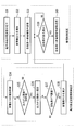
- FIG. 2 is a block diagram illustrating a schematic configuration of the wind turbine generator 1.
- the wind turbine generator 1 is a double-feed variable-speed wind turbine system (double-fed). This is a kind of variable speed wind turbine system. That is, the wind power generation system 1 of the present embodiment is configured such that the power generated by the generator 5 can be output to both the stator winding and the rotor winding to the power system 13. Specifically, in the generator 5, the stator winding is directly connected to the power system 13, and the rotor winding is connected to the power system 13 via the inverter device 17.
- the inverter device 17 is composed of a generator-side inverter 14, a DC bus 15, and a system-side inverter 16, and converts AC power received from the rotor winding into AC power adapted to the frequency of the power system 13.
- the generator-side inverter 14 converts AC power generated in the rotor winding into DC power, and outputs the DC power to the DC bus 15.
- the system side inverter 16 performs voltage control of the DC bus 15, whereby the system side inverter 16 receives power from the system side. That is, the system-side inverter 16 converts the DC power received from the DC bus 15 into AC power having the same frequency as that of the power system 13 and outputs the AC power to the power system 13.
- the power generation output that the generator 5 outputs to the power system 13 is controlled by the generator-side inverter 14.
- the inverter device 17 also has a function of converting AC power received from the power system 13 into AC power adapted to the frequency of the rotor winding, and excites the rotor winding depending on the operating state of the wind power generation system 1. Also used for.
- the system-side inverter 16 converts AC power into DC power and outputs the DC power to the DC bus 15.
- the generator-side inverter 14 converts the DC power received from the DC bus 15 into AC power adapted to the frequency of the rotor winding, and supplies the AC power to the rotor winding of the generator 5.
- the control system of the wind power generation system 1 includes a PLG (pulse logic generator) 18, a sensor 19, and a control device 20.
- the PLG 18 measures the rotation speed of the generator 5 (hereinafter referred to as “rotation speed”) and outputs the measurement result to the control device 20.
- the sensor 19 is provided on a power line that connects the generator 5 to the power system 13.
- the voltage Vgrid of the power system 13, the current Igrid output from the generator 5 to the power system 13, and the frequency of the power system 13 (hereinafter, referred to as “power grid 13”). (Referred to as “system frequency”), and the measurement result is output to the control device 20.
- the control device 20 includes a converter control unit 21, a pitch control unit 22, and a main control unit 23.
- the main control unit 23 calculates a power generation output output to the power system 13 from the output current Igrid and the voltage Vgrid that are outputs of the sensor 19.
- the main control unit 23 generates control signals for the converter control unit 21 and the pitch control unit 22 in response to the rotation speed that is the output of the PLG 18, the output current Igrid that is the output of the sensor 19, the voltage Vgrid, and the system frequency.
- the converter control unit 21 controls the power output of the wind power generator 1 by controlling the power transistor of the generator-side inverter 14 based on the control signal from the main control unit 23. By controlling the power transistor of the system side inverter 16, the voltage of the DC bus 15 is controlled to a predetermined value.
- the pitch control unit 22 controls the pitch angle of the blade 8 based on a control signal from the main control unit 23.
- the converter control unit 21 Control is made to increase the power generation output regardless of the fluctuation of the rotation speed. More specifically, for example, when the wind speed decreases and the rotation speed of the generator 5 decreases, the power generation output also decreases as it is. However, in the converter control unit 21 in this embodiment, the rotation speed of the generator 5 is reduced. Control is performed to increase the power generation output even if the power decreases.
- the pitch angle control unit 22 controls the pitch angle of the blade 8 to be fine based on a control signal from the main control unit 23. Based on the control signal from the main control unit 23, the inverter control unit 17 is controlled by the converter control unit 21 to increase the generator torque, and the inertia energy of the wind turbine rotor 7 is converted and recovered into the power generation output.
- the pitch angle control unit 22 and the converter control unit 21 respectively control the blade 8 and the inverter device 17 so as to maintain the rated output when the power generation output of the wind turbine generator 1 increases and reaches the rated output. To do. Further, when the rotational speed of the generator 5 becomes less than the lower limit value, the power generation output is controlled to be decreased, thereby increasing the rotational speed of the generator 5.
- the converter control unit 21 reduces the power generation output when the system frequency is equal to or higher than the predetermined rated frequency and when the rotational speed of the generator 5 is less than the upper limit value (second predetermined value).
- the pitch angle control unit 22 controls the pitch angle of the blade 8 to be a feather based on a control signal from the main control unit 23.
- the inverter control unit 21 is controlled by the converter control unit 21 to reduce the generator torque, and the wind force acting on the blade 8 is converted into the inertia energy of the wind turbine rotor 7 and stored. Reduce power generation output.
- the pitch angle control unit 22 and the converter control unit 21 reduce the power generation output of the lower limit value when the power generation output of the wind turbine generator 1 decreases and the power generation output decreases to a predetermined lower limit value (predetermined output). Control to maintain. Furthermore, when the rotation speed of the generator 5 becomes more than an upper limit value, it controls to increase a power generation output. This prevents over-rotation of the generator 5.
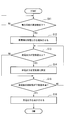
- FIG. 3 is a flowchart showing a control process when the frequency of the power system 13 is lowered in the wind turbine generator 1 according to the present embodiment.
- step S ⁇ b> 11 of FIG. 3 in response to the output from the sensor 19, the control device 20 determines whether or not the system frequency has decreased to a predetermined rated value frequency or less. If it is determined that the system frequency is not lower than the rated frequency, the process of step S11 is repeated, and subsequently it is determined whether the system frequency has decreased at a predetermined time interval with respect to the detection result from the sensor 19. To do. If it is determined in step S11 that the system frequency is equal to or lower than the predetermined rated value frequency, the process proceeds to the next step S12.
- the control device 20 controls the wind power generator 1 to increase its power generation output in response to a decrease in the system frequency. This is to stabilize the power system 13 by increasing the power generation output and suppressing fluctuations in the system frequency.
- main controller 23 outputs an output increase control signal to converter controller 21 and pitch angle controller 22 so as to increase the power generation output.
- the pitch angle control unit 22 controls the blade 8 so that the pitch angle becomes fine, or the converter control device 21 increases the power generation output.
- the inverter 14 is controlled.
- the main controller 23 when the wind speed is in the vicinity of the rated wind speed, when the system frequency decreases, the main controller 23 outputs an output increase control signal.
- the pitch angle control unit 22 controls the blade 8 so that the pitch angle becomes fine to increase the power generation output. Even if the wind speed is reduced and the pitch angle of the blade 8 is fine, the rotational speed of the generator 5 is reduced, and if the pitch angle control is insufficient to maintain the power generation output at the rated value, the converter control device is further provided. 21, the generator-side inverter 14 is controlled to increase the power generation output by converting the rotor inertia energy into the power generation output.
- the power generation output is also less than the rated value.
- the converter control device 21 converts the rotor inertia energy into the power generation output to increase the power generation output.
- the generator-side inverter 14 is controlled.
- step S13 the main control unit 23 calculates the power generation output output to the power system 13 in response to the detection result of the output current Igrid and the voltage Vgrid from the sensor 19, and the power generation output as the calculation result is predetermined. It is determined whether or not it is equal to or higher than the rated value. In this determination, if the power generation output is less than the predetermined rated value, the process proceeds to step S15, and if it is greater than the predetermined rated value, the process proceeds to step S14. In step S14, the control device 20 controls the pitch angle of the blade 8 and the generator-side inverter 14 to maintain the power generation output at the rated value.
- step S15 it is determined whether or not the rotational speed of the generator 5 is less than the lower limit value.
- the process returns to step S13 and the above-described processing is repeated, and when it is determined that the rotational speed of the generator 5 is less than the lower limit value.
- step S16 when the rotation speed of the generator 5 becomes less than the lower limit value, the operation of the wind turbine generator 1 cannot be continued if the rotation speed further decreases. Therefore, in order to avoid this, the control device 20 outputs the power generation output. By controlling the wind turbine generator 1 so as to decrease, the rotational speed of the generator 5 is increased, and this routine is terminated.
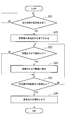
- FIG. 5 is a flowchart showing a control process when the frequency of the power system 13 is increased in the wind turbine generator 1 according to the present embodiment.
- step S ⁇ b> 21 of FIG. 5 in response to the output from the sensor 19, the control device 20 determines whether or not the system frequency has increased to a predetermined rated frequency or higher. If it is determined that the system frequency is not equal to or higher than the rated frequency, the process of step S21 is repeated, and it is subsequently determined whether the system frequency has decreased at a predetermined time interval with respect to the detection result from the sensor 19. To do. If it is determined in step S21 that the system frequency is equal to or higher than the predetermined rated value frequency, the process proceeds to the next step S22.
- the control device 20 controls the wind power generator 1 to decrease its power generation output in response to the increase in the system frequency. This is because the power system 13 is stabilized by reducing the power generation output and suppressing the fluctuation of the system frequency.
- main controller 23 outputs an output decrease control signal to converter controller 21 and pitch angle controller 22 so as to decrease the power generation output.
- the pitch angle control unit 22 controls the blade 8 so that the pitch angle becomes a feather, or the converter control device 21 reduces the power generation output.
- the inverter 14 is controlled.
- the pitch angle control unit 22 causes the pitch angle of the blade 8 to respond to the output reduction control signal. Control to become a feather. If the power generation output is not sufficiently reduced even if the pitch angle of the blade 8 is a feather, or if it is desired to further reduce the output, the generator-side inverter 14 is controlled so as to decrease the power generation output.
- the power generation output is also less than the rated value.
- the generator-side inverter 14 is controlled so as to further decrease the power generation output.
- step S23 the main control unit 23 calculates the power generation output to be output to the power system 13 in response to the detection result of the output current Igrid and the voltage Vgrid from the sensor 19, and the power generation output as the calculation result is predetermined. It is determined whether it is below the lower limit value. In this determination, if it is determined that the power generation output is equal to or less than the predetermined lower limit value, the process proceeds to step S25, and if it is determined not to be equal to or less than the predetermined lower limit value, the process proceeds to step S24.
- step S24 the control device 20 controls the pitch angle of the blade 8 and the generator-side inverter 14 to maintain the power generation output at the lower limit.
- step S25 it is determined whether or not the rotational speed of the generator 5 is equal to or higher than the upper limit value. This is because the inverter control in step S22 acts in the direction in which the rotational speed of the generator 5 increases. If it is determined in this determination that the rotational speed of the generator 5 is not equal to or greater than the upper limit value, the process returns to step S23 and the above-described processing is repeated, and it is determined that the rotational speed of the generator 5 is equal to or greater than the upper limit value. Advances to the next Step S26. In step S26, when the rotational speed of the generator 5 exceeds the upper limit value, if the operation of the wind power generator 1 is continued as it is, the power generator may be damaged due to over-rotation. , That is, the control device 20 controls the generator-side inverter 14 so as to increase the power generation output, and this routine is terminated.
- the frequency variation is determined based on the predetermined rated frequency.
- the present invention is not limited to such a configuration, and an allowable range is determined for the predetermined rated frequency, and the frequency is It is also possible to determine the frequency variation based on whether or not it falls within the allowable range.
- the power generation output usually depends on the wind conditions and the generator rotation speed.
- the power system can be stabilized by arbitrarily increasing or decreasing the power generation output of the wind turbine generator in response to fluctuations in the frequency of the power system.
- a so-called winding induction generator is used as the generator 5 and an inverter device 17 including a generator-side inverter 14, a DC bus 15, and a system-side inverter 16 is used.
- the stator winding is directly connected to the power system 13 and the rotor winding is connected to the power system 13 via the inverter device 17 (see FIG. 2).
- the stator windings of the generator are directly connected to the power system, if the frequency of the power system fluctuates, the generator output is directly affected.
- a multi-pole synchronous generator is used as a generator, and the stator winding is connected to the power system via an inverter device composed of an inverter and a converter.
- the present embodiment relates to a wind power generation system called a wind park or wind farm, in which a plurality of wind power generation apparatuses 1 according to the first embodiment described above are provided.
- the wind power generation system of the present embodiment is connected to each other by a communication line so as to be able to transmit and receive information such as control signals to and from the plurality of wind power generation devices 1 and manage each wind power generation device.
- -It has a management control device to control.
- the management control device is realized by using a general-purpose or dedicated computer equipped with a CPU (Central Processing Unit), ROM (Read Only Memory), RAM (Random Access Memory), etc., and a program operating on this computer. Can do.
- the CPU or the like reads out a program recorded on a computer-readable recording medium on which a program for realizing all or part of the above processing is recorded, and expands the program in a ROM or RAM.
- the CPU Central Processing Unit
- ROM Read Only Memory
- RAM Random Access Memory
- the CPU or the like reads out a program recorded on a computer-readable recording medium on which a program for realizing all or part of the above processing is recorded, and expands the program in a ROM or RAM.
- it By executing information processing / arithmetic processing, it functions as a management control device, and manages and controls the wind turbine generator.
- the computer-readable recording medium means a magnetic disk, a magneto-optical disk, a CD-ROM, a DVD-ROM, a semiconductor memory, or the like.
- the computer program may be distributed to the computer via a communication line, and the computer that has received the distribution may execute the program.
- FIG. 8 is a flowchart showing a control process when the frequency of the power system is lowered in the wind power generation system according to the present embodiment.
- the management control device detects the system frequency, detects that the system frequency is equal to or lower than a predetermined rated value, and proceeds to the next step S32.
- the detection of the system frequency may be based on an output from a sensor provided in each wind turbine generator, or the management control device may be provided with a sensor for detecting the system frequency independently and manage the power system. The command from the electric power company may be replaced with this.
- the management control device determines to increase the power generation output of the wind power generation system in response to the decrease in the system frequency, and proceeds to the next step S33. This is to stabilize the power system by increasing the power generation output and suppressing fluctuations in the system frequency.
- a power generation increase command (first control signal) for increasing the power generation output of each wind turbine generator 1 is sent from the management controller to all wind turbine generators 1 connected to the management controller. Send.
- the control device 20 of each wind turbine generator 1 receives the power generation increase command from the management control device, and controls the power generation output to increase in response to the power generation increase command.
- the pitch angle control unit 22 controls the blade 8 so that the pitch angle becomes fine, or the converter control device 21
- the generator-side inverter 14 is controlled to increase the power generation output.
- step S35 the main control unit 23 of the wind turbine generator 1 calculates the power generation output output from the sensor 19 to the power system 13 in response to the detection result of the output current Igrid and the voltage Vgrid. It is determined whether a certain power generation output is equal to or higher than a predetermined rated value. In this determination, if the power generation output is less than the predetermined rated value, the process proceeds to step S37, and if it is greater than the predetermined rated value, the process proceeds to step S36. In step S36, the control device 20 controls the pitch angle of the blade 8 and the generator-side inverter 14 to fix the power generation output at the upper limit (rated value).
- step S37 it is determined whether or not the rotational speed of the generator 5 is less than the lower limit value.
- the process returns to step S35 and the above-described processing is repeated, and when it is determined that the rotational speed of the generator 5 is less than the lower limit value.
- step S38 when the rotational speed of the generator 5 becomes less than the lower limit value, the operation of the wind turbine generator 1 cannot be continued if the rotational speed further decreases.
- the wind turbine generator 1 is controlled so as to decrease.
- the control device 20 transmits the information to the management control device.
- step S39 the management control device receives information indicating that the power generation output from each wind power generation device 1 has been reduced, and determines whether or not the power generation outputs of all the wind power generation devices 1 have decreased. This determination is repeated until the power generation outputs of all the wind power generators 1 are decreased, and when it is determined that the power generation outputs of all the wind power generation apparatuses are decreased, the process proceeds to the next step S40.
- step S40 in response to the decrease in the power generation output of all the wind turbine generators 1, a cancellation command is transmitted to all the wind turbine generators 1 to cancel the power generation increase command transmitted in step S33. Then, this routine ends.
- FIG. 9 is a flowchart showing a control process when the frequency of the power system rises in the wind power generation system according to the present embodiment.
- step S41 the management control device detects the system frequency, detects that the system frequency is equal to or higher than a predetermined rated value, and proceeds to the next step S42.
- the detection of the system frequency may be based on an output from a sensor provided in each wind turbine generator, or the management control device may be provided with a sensor for detecting the system frequency independently and manage the power system. The command from the electric power company may be replaced with this.
- the management control device determines to reduce the power generation output of the wind power generation system in response to the increase in the system frequency, and proceeds to the next step S43. This is because the power system is stabilized by lowering the system frequency and suppressing the fluctuation of the system frequency.
- a power generation reduction command (second control signal) for reducing the power generation output of each wind turbine generator 1 is sent from the management controller to all wind turbine generators 1 connected to the management controller. Send.
- the control device 20 of each wind turbine generator 1 receives the power generation reduction command from the management control device, and controls the power generation output to decrease in response to the power generation reduction command. Specifically, like the wind power generator 1 in the first embodiment described above, the pitch angle control unit 22 controls the blade 8 so that the pitch angle becomes a feather, or the converter control device 21 The generator-side inverter 14 is controlled so as to reduce the power generation output.
- step S45 the main control unit 23 of the wind turbine generator 1 calculates the power generation output that is output from the sensor 19 to the power system 13 in response to the detection result of the output current Igrid and the voltage Vgrid. It is determined whether or not a certain power generation output is greater than or equal to a predetermined lower limit value. In this determination, if the power generation output is less than the predetermined lower limit value, the process proceeds to step S47, and if it is greater than the predetermined lower limit value, the process proceeds to step S46. In step S46, the control device 20 controls the pitch angle of the blade 8 and the generator-side inverter 14 to fix the power generation output at the lower limit value.
- step S47 it is determined whether or not the rotational speed of the generator 5 is equal to or higher than the upper limit value. If it is determined in this determination that the rotational speed of the generator 5 is not greater than or equal to the upper limit value, the process returns to step S45 and the above-described processing is repeated, and if it is determined that the rotational speed of the generator 5 is greater than or equal to the upper limit value. Advances to the next Step S48.
- step S48 when the rotational speed of the generator 5 exceeds the upper limit value, if the rotational speed further increases, the wind power generator 1 may be damaged. The wind power generator 1 is controlled to increase. When the power generation output of the wind turbine generator 1 is increased, the control device 20 transmits the information to the management control device.
- step S49 the management control device receives information indicating that the power generation output from each wind power generation device 1 has been increased, and determines whether or not the power generation outputs of all the wind power generation devices 1 have increased. This determination is repeated until the power generation outputs of all the wind power generators 1 increase, and when it is determined that the power generation outputs of all the wind power generation apparatuses have increased, the process proceeds to the next step S50.
- step S50 in response to the decrease in the power generation output of all the wind turbine generators 1, a cancellation command is transmitted to all the wind turbine generators 1 to cancel the power generation reduction command transmitted in step S43. Then, this routine ends.
- the cancellation command may be transmitted when the system frequency recovers and becomes a rated frequency, or when a predetermined time has elapsed.
- control signals such as a power generation increase command or a power generation decrease command from the management control device have been transmitted to all wind power generation devices, but it is not always necessary to have such a configuration. It can also be set as the structure transmitted with respect to some wind power generators.
- each wind power generator receives a power generation increase command or a power generation decrease command from the management control device, the power generation output can be immediately controlled according to these commands.
- each wind turbine generator is configured to determine whether to control the power generation output in the control device of its own wind turbine generator based on the power generation increase command or the power generation decrease command from the management controller.
- the frequency variation is determined based on the predetermined rated frequency.
- the present invention is not limited to such a configuration, and an allowable range is determined for the predetermined rated frequency, and the frequency is It is also possible to determine the frequency variation based on whether or not it falls within the allowable range.
- a plurality of wind power generators can be used in response to the frequency variation of the power system under a wide range of wind conditions and generator speed conditions.
- the power system can be stabilized by arbitrarily increasing or decreasing the power generation output of the wind power generation system including the power generation system.
Priority Applications (3)
| Application Number | Priority Date | Filing Date | Title |
|---|---|---|---|
| EP10806278.7A EP2463519B2 (de) | 2009-08-06 | 2010-05-21 | Windturbinegenerator, steuerverfahren für den windturbinegenerator, windturbineerzeugungssystem und steuerverfahren für das windturbineerzeugungssystem |
| AU2010280169A AU2010280169A1 (en) | 2009-08-06 | 2010-05-21 | Wind-power generation device, control method for wind-power generation device, wind-power generation system, and control method for wind-power generation system |
| CN201080025811.7A CN102472249B (zh) | 2009-08-06 | 2010-05-21 | 风力发电装置、风力发电装置的控制方法、风力发电系统及风力发电系统的控制方法 |
Applications Claiming Priority (2)
| Application Number | Priority Date | Filing Date | Title |
|---|---|---|---|
| JP2009-183532 | 2009-08-06 | ||
| JP2009183532A JP5550283B2 (ja) | 2009-08-06 | 2009-08-06 | 風力発電装置、風力発電装置の制御方法、風力発電システム及び風力発電システムの制御方法 |
Publications (1)
| Publication Number | Publication Date |
|---|---|
| WO2011016278A1 true WO2011016278A1 (ja) | 2011-02-10 |
Family
ID=43534248
Family Applications (1)
| Application Number | Title | Priority Date | Filing Date |
|---|---|---|---|
| PCT/JP2010/058619 WO2011016278A1 (ja) | 2009-08-06 | 2010-05-21 | 風力発電装置、風力発電装置の制御方法、風力発電システム及び風力発電システムの制御方法 |
Country Status (7)
| Country | Link |
|---|---|
| US (2) | US8378643B2 (de) |
| EP (1) | EP2463519B2 (de) |
| JP (1) | JP5550283B2 (de) |
| KR (1) | KR20120025499A (de) |
| CN (1) | CN102472249B (de) |
| AU (1) | AU2010280169A1 (de) |
| WO (1) | WO2011016278A1 (de) |
Cited By (4)
| Publication number | Priority date | Publication date | Assignee | Title |
|---|---|---|---|---|
| WO2012114487A1 (ja) * | 2011-02-23 | 2012-08-30 | 三菱重工業株式会社 | 風力発電装置の制御装置、風力発電装置、及び風力発電装置の制御方法 |
| WO2012117491A1 (ja) * | 2011-02-28 | 2012-09-07 | 三菱重工業株式会社 | 風力発電装置およびその制御方法 |
| WO2013021481A1 (ja) * | 2011-08-10 | 2013-02-14 | 三菱重工業株式会社 | 風力発電所の制御装置及び風力発電所の制御方法 |
| CN102971528A (zh) * | 2012-02-24 | 2013-03-13 | 三菱重工业株式会社 | 风车控制装置及其方法和风力发电系统 |
Families Citing this family (42)
| Publication number | Priority date | Publication date | Assignee | Title |
|---|---|---|---|---|
| CA2557396C (en) * | 2004-02-27 | 2010-12-21 | Mitsubishi Heavy Industries, Ltd. | Wind turbine generator, active damping method thereof, and windmill tower |
| WO2010044163A1 (ja) * | 2008-10-16 | 2010-04-22 | 三菱重工業株式会社 | 風力発電システム、及びその制御方法 |
| JP5320311B2 (ja) * | 2010-01-18 | 2013-10-23 | 三菱重工業株式会社 | 可変速発電装置及びその制御方法 |
| EP2603696B1 (de) * | 2010-08-13 | 2015-04-08 | Vestas Wind Systems A/S | Windkrafterzeugung mit verringerten Leistungsschwankungen |
| US20120104753A1 (en) * | 2010-10-29 | 2012-05-03 | Mitsubishi Heavy Industries, Ltd. | Control system of wind power generator, wind farm, and method for controlling wind power generator |
| EP2458205B1 (de) * | 2010-11-26 | 2016-10-19 | Siemens Aktiengesellschaft | Verfahren und System zur Steuerung einer elektrischen Vorrichtung einer Windturbine |
| JP2012143079A (ja) | 2010-12-28 | 2012-07-26 | Mitsubishi Heavy Ind Ltd | ケーブル支持具 |
| JP5455890B2 (ja) * | 2010-12-28 | 2014-03-26 | 三菱重工業株式会社 | 風力発電装置の制御装置、風力発電システム、及び風力発電装置の制御方法 |
| DE102011006670A1 (de) * | 2011-04-01 | 2012-10-04 | Aloys Wobben | Windenergieanlage und Verfahren zum Betreiben einer Windenergieanlage |
| EP2726733B1 (de) * | 2011-06-30 | 2016-07-27 | Vestas Wind Systems A/S | System sowie verfahren zur regelung der ausgangsleistung einer windturbine oder windturbinenanlage |
| WO2013010332A1 (en) * | 2011-07-21 | 2013-01-24 | Vestas Wind Systems A/S | Method of operating wind turbine and controller thereof |
| EP2557678B1 (de) * | 2011-08-09 | 2014-05-07 | Siemens Aktiengesellschaft | Anordnung zur Erzeugung eines Steuersignals zur Steuerung der Beschleunigung eines Generators |
| CN102305180B (zh) * | 2011-08-31 | 2013-07-31 | 国电联合动力技术有限公司 | 一种差动齿箱调速型同步风力发电机组的控制方法和系统 |
| CN103827483B (zh) * | 2011-09-30 | 2016-08-17 | 维斯塔斯风力系统集团公司 | 包含电站损失的快速回流控制 |
| JP2013087703A (ja) * | 2011-10-19 | 2013-05-13 | Mitsubishi Heavy Ind Ltd | 風力発電装置及びその方法並びにプログラム |
| CN102506477B (zh) * | 2011-10-23 | 2014-01-29 | 西安交通大学 | 热电联产机组与风力发电联合制冷系统及其调度方法 |
| US8736094B2 (en) | 2012-01-20 | 2014-05-27 | Mitsubishi Heavy Industries, Ltd. | Wind-turbine-generator control system, wind turbine generator, wind farm, and wind-turbine-generator control method |
| JP5713927B2 (ja) * | 2012-01-20 | 2015-05-07 | 三菱重工業株式会社 | 風力発電装置の制御装置、風力発電装置、ウインドファーム、及び風力発電装置の制御方法 |
| JP5245017B1 (ja) * | 2012-02-24 | 2013-07-24 | 三菱重工業株式会社 | 風力発電システム及びその制御方法 |
| WO2013125043A1 (ja) * | 2012-02-24 | 2013-08-29 | 三菱重工業株式会社 | 風力発電システム、その制御装置、及びその制御方法 |
| DE102012203334A1 (de) * | 2012-03-02 | 2013-09-05 | Wobben Properties Gmbh | Verfahren zum Betreiben eines Kombikraftwerks bzw. Kombikraftwerk |
| CN104285059B (zh) | 2012-05-11 | 2017-03-01 | 维斯塔斯风力系统集团公司 | 风力发电厂频率控制 |
| US20130320937A1 (en) * | 2012-06-05 | 2013-12-05 | General Electric Company | System and method to stabilize power supply |
| DE102012215575A1 (de) | 2012-09-03 | 2014-03-06 | Wobben Properties Gmbh | Verfahren und Regeleinrichtung für eine Windenergieanlage sowie Computerprogrammprodukt, digitales Speichermedium und Windenergieanlage |
| EP2708737B1 (de) * | 2012-09-12 | 2020-10-28 | General Electric Technology GmbH | Verfahren zum Betrieb eines Wärmekraftwerks |
| US9115695B2 (en) * | 2013-07-16 | 2015-08-25 | Siemens Aktiengesellschaft | Method and arrangement for controlling a wind turbine |
| US9450416B2 (en) * | 2013-07-16 | 2016-09-20 | Siemens Aktiengesellschaft | Wind turbine generator controller responsive to grid frequency change |
| ES2545674B1 (es) * | 2014-03-11 | 2016-06-29 | Gamesa Innovation & Technology, S.L. | Sistema de control de inercia para aerogenerador |
| JP2016013039A (ja) * | 2014-06-30 | 2016-01-21 | 住友電気工業株式会社 | 送電システム、及び送電システムの運転方法 |
| KR101564978B1 (ko) * | 2014-07-15 | 2015-11-02 | 전북대학교산학협력단 | 풍력발전기의 적응형 관성 제어 방법 |
| KR20160080830A (ko) | 2014-12-29 | 2016-07-08 | 노츠 주식회사 | 배관을 이용한 재생 에너지 수집 장치 및 시스템 |
| EP3303833A1 (de) | 2015-06-03 | 2018-04-11 | Vestas Wind Systems A/S | Overboost-verfahren für eine windkraftanlage |
| JP6276223B2 (ja) * | 2015-07-16 | 2018-02-07 | 株式会社日本製鋼所 | 風力発電装置、風力発電制御装置および風力発電制御プログラム |
| DE102016106215A1 (de) | 2016-04-05 | 2017-10-05 | Wobben Properties Gmbh | Verfahren sowie Windenergieanlage zum Einspeisen elektrischer Leistung |
| US10074985B2 (en) * | 2016-06-21 | 2018-09-11 | The Aerospace Corporation | Solar and/or wind inverter |
| EP3545190A1 (de) * | 2016-11-25 | 2019-10-02 | Vestas Wind Systems A/S | Verfahren zur steuerung einer windturbine, steuergerät für eine windturbine sowie windturbine |
| CN109931217B (zh) * | 2017-12-15 | 2020-05-12 | 新疆金风科技股份有限公司 | 风力发电机组停机控制方法及系统 |
| CN110098622B (zh) | 2018-01-31 | 2021-04-13 | 北京金风科创风电设备有限公司 | 风电机组的一次调频方法和设备 |
| KR102225611B1 (ko) * | 2019-06-18 | 2021-03-12 | 연세대학교 산학협력단 | 주파수 안정도 향상을 위한 재생에너지 발전기의 제어 시스템 및 방법 |
| JP7379062B2 (ja) * | 2019-10-04 | 2023-11-14 | 株式会社東芝 | 電源制御装置および電源制御システム |
| US11754056B1 (en) | 2021-03-26 | 2023-09-12 | Hawk Spider Energy Corp. | Dynamic mass torque generator |
| KR102539829B1 (ko) * | 2021-07-14 | 2023-06-02 | 연세대학교 산학협력단 | 발전기의 관성 제어 방법 및 이를 이용한 관성 제어 시스템 |
Citations (4)
| Publication number | Priority date | Publication date | Assignee | Title |
|---|---|---|---|---|
| JPH1156126A (ja) * | 1997-08-13 | 1999-03-02 | Toshio Iwata | 送風兼発電方法及び装置 |
| JPH1169893A (ja) * | 1997-08-26 | 1999-03-09 | Hitachi Eng & Services Co Ltd | ハイブリッド発電システム |
| JP2003535561A (ja) | 2000-05-11 | 2003-11-25 | アロイス・ヴォベン | 風力装置の操作方法及び風力装置 |
| JP2008278725A (ja) * | 2007-05-07 | 2008-11-13 | Hitachi Ltd | 風力発電システム及びその制御方法及びこれを用いた風力発電所 |
Family Cites Families (18)
| Publication number | Priority date | Publication date | Assignee | Title |
|---|---|---|---|---|
| JPS61240900A (ja) * | 1985-04-15 | 1986-10-27 | Oriental Kiden Kk | 風車発電装置 |
| US5083039B1 (en) * | 1991-02-01 | 1999-11-16 | Zond Energy Systems Inc | Variable speed wind turbine |
| JP4056713B2 (ja) * | 2001-03-26 | 2008-03-05 | 株式会社MERSTech | 風力発電設備 |
| ES2189664B1 (es) | 2001-09-13 | 2004-10-16 | Made Tecnologias Renovables, S.A. | Sistema de aprovechamiento de la energia almacenada en la inercia mecanica del rotor de una turbina eolica. |
| US7245037B2 (en) * | 2002-09-13 | 2007-07-17 | Abb Ab | Wind power fed network |
| EP1467463B1 (de) * | 2003-04-09 | 2016-12-21 | General Electric Company | Windpark und Verfahren zum Betrieb des Windparks |
| WO2005025026A1 (de) | 2003-09-03 | 2005-03-17 | Repower Systems Ag | Verfahren zum betrieb bzw. regelung einer windenergieanlage sowie verfahren zur bereitstellung von primärrefelleistung mit windenergieanlagen |
| GB2407440B (en) * | 2003-09-23 | 2006-02-22 | Responsiveload Ltd | Grid stabilising system |
| US7504738B2 (en) | 2005-09-29 | 2009-03-17 | General Electric Company | Wind turbine and method for operating same |
| US7345373B2 (en) | 2005-11-29 | 2008-03-18 | General Electric Company | System and method for utility and wind turbine control |
| ES2552058T3 (es) * | 2006-10-19 | 2015-11-25 | Siemens Aktiengesellschaft | Instalación de energía eólica y método para controlar la potencia de salida de una instalación de energía eólica |
| US9020650B2 (en) * | 2007-02-13 | 2015-04-28 | General Electric Company | Utility grid, controller, and method for controlling the power generation in a utility grid |
| CN100464493C (zh) * | 2007-03-13 | 2009-02-25 | 西安理工大学 | 基于数控飞轮混合驱动的风力发电变速恒频方法及其装置 |
| US8237301B2 (en) * | 2008-01-31 | 2012-08-07 | General Electric Company | Power generation stabilization control systems and methods |
| JP4698718B2 (ja) * | 2008-09-30 | 2011-06-08 | 株式会社日立製作所 | 風力発電装置群の制御装置及び制御方法 |
| DE102009014012B4 (de) * | 2009-03-23 | 2014-02-13 | Wobben Properties Gmbh | Verfahren zum Betreiben einer Windenergieanlage |
| ES2561842T3 (es) * | 2009-06-29 | 2016-03-01 | Vestas Wind Systems A/S | Turbina eólica que proporciona soporte a la red de distribución |
| US8219256B2 (en) * | 2009-07-14 | 2012-07-10 | Siemens Aktiengesellschaft | Bang-bang controller and control method for variable speed wind turbines during abnormal frequency conditions |
-
2009
- 2009-08-06 JP JP2009183532A patent/JP5550283B2/ja active Active
-
2010
- 2010-05-21 WO PCT/JP2010/058619 patent/WO2011016278A1/ja active Application Filing
- 2010-05-21 KR KR1020117028946A patent/KR20120025499A/ko not_active Application Discontinuation
- 2010-05-21 EP EP10806278.7A patent/EP2463519B2/de active Active
- 2010-05-21 AU AU2010280169A patent/AU2010280169A1/en not_active Abandoned
- 2010-05-21 CN CN201080025811.7A patent/CN102472249B/zh active Active
- 2010-07-29 US US12/845,984 patent/US8378643B2/en active Active
-
2013
- 2013-02-15 US US13/768,538 patent/US20130193934A1/en not_active Abandoned
Patent Citations (4)
| Publication number | Priority date | Publication date | Assignee | Title |
|---|---|---|---|---|
| JPH1156126A (ja) * | 1997-08-13 | 1999-03-02 | Toshio Iwata | 送風兼発電方法及び装置 |
| JPH1169893A (ja) * | 1997-08-26 | 1999-03-09 | Hitachi Eng & Services Co Ltd | ハイブリッド発電システム |
| JP2003535561A (ja) | 2000-05-11 | 2003-11-25 | アロイス・ヴォベン | 風力装置の操作方法及び風力装置 |
| JP2008278725A (ja) * | 2007-05-07 | 2008-11-13 | Hitachi Ltd | 風力発電システム及びその制御方法及びこれを用いた風力発電所 |
Non-Patent Citations (1)
| Title |
|---|
| See also references of EP2463519A4 * |
Cited By (13)
| Publication number | Priority date | Publication date | Assignee | Title |
|---|---|---|---|---|
| WO2012114487A1 (ja) * | 2011-02-23 | 2012-08-30 | 三菱重工業株式会社 | 風力発電装置の制御装置、風力発電装置、及び風力発電装置の制御方法 |
| US9222464B2 (en) | 2011-02-23 | 2015-12-29 | Mitsubishi Heavy Industries, Ltd. | Controller for wind turbine generator, wind turbine generator, and method of controlling wind turbine generator |
| KR101253460B1 (ko) | 2011-02-23 | 2013-04-10 | 미츠비시 쥬고교 가부시키가이샤 | 풍력 발전 장치의 제어 장치, 풍력 발전 장치 및 풍력 발전 장치의 제어 방법 |
| JP5204307B2 (ja) * | 2011-02-23 | 2013-06-05 | 三菱重工業株式会社 | 風力発電装置の制御装置、風力発電装置、及び風力発電装置の制御方法 |
| JP5237454B2 (ja) * | 2011-02-28 | 2013-07-17 | 三菱重工業株式会社 | 風力発電装置およびその制御方法 |
| WO2012117491A1 (ja) * | 2011-02-28 | 2012-09-07 | 三菱重工業株式会社 | 風力発電装置およびその制御方法 |
| US9287814B2 (en) | 2011-02-28 | 2016-03-15 | Mitsubishi Heavy Industries, Ltd. | Wind turbine generator and method of controlling the same |
| KR101253468B1 (ko) | 2011-02-28 | 2013-04-10 | 미츠비시 쥬고교 가부시키가이샤 | 풍력 발전 장치 및 그 제어 방법 |
| US8395272B2 (en) | 2011-08-10 | 2013-03-12 | Mitsubishi Heavy Industries, Ltd. | Wind-power-station control apparatus and wind-power-station control method |
| WO2013021481A1 (ja) * | 2011-08-10 | 2013-02-14 | 三菱重工業株式会社 | 風力発電所の制御装置及び風力発電所の制御方法 |
| WO2013125044A1 (ja) * | 2012-02-24 | 2013-08-29 | 三菱重工業株式会社 | 風車制御装置及びその方法並びに風力発電システム |
| JP5325348B1 (ja) * | 2012-02-24 | 2013-10-23 | 三菱重工業株式会社 | 風車制御装置及びその方法並びに風力発電システム |
| CN102971528A (zh) * | 2012-02-24 | 2013-03-13 | 三菱重工业株式会社 | 风车控制装置及其方法和风力发电系统 |
Also Published As
| Publication number | Publication date |
|---|---|
| KR20120025499A (ko) | 2012-03-15 |
| EP2463519A1 (de) | 2012-06-13 |
| EP2463519A4 (de) | 2014-12-10 |
| CN102472249A (zh) | 2012-05-23 |
| US20130193934A1 (en) | 2013-08-01 |
| US20110031748A1 (en) | 2011-02-10 |
| US8378643B2 (en) | 2013-02-19 |
| AU2010280169A1 (en) | 2012-01-19 |
| EP2463519B1 (de) | 2018-12-05 |
| EP2463519B2 (de) | 2021-10-27 |
| JP2011038406A (ja) | 2011-02-24 |
| CN102472249B (zh) | 2014-07-16 |
| JP5550283B2 (ja) | 2014-07-16 |
Similar Documents
| Publication | Publication Date | Title |
|---|---|---|
| JP5550283B2 (ja) | 風力発電装置、風力発電装置の制御方法、風力発電システム及び風力発電システムの制御方法 | |
| US10418925B2 (en) | Wind turbine providing grid support | |
| JP5339451B2 (ja) | 励磁機及び系統に接続されていない電力変換器を有する可変速風力タービンの発電ブレーキ(dynamicelectricbrake) | |
| US9450416B2 (en) | Wind turbine generator controller responsive to grid frequency change | |
| JP5237454B2 (ja) | 風力発電装置およびその制御方法 | |
| JP2012516667A (ja) | 発電システムのための電力システム周波数慣性 | |
| CN111520283B (zh) | 风力涡轮机控制 | |
| CN111936740B (zh) | 用于功率系统的无功电流裕度调节器 | |
| KR101141090B1 (ko) | 풍력 발전 장치의 제어 장치, 윈드팜, 및 풍력 발전 장치의 제어 방법 | |
| US9739264B2 (en) | Method of operating a wind turbine | |
| KR20100114387A (ko) | 선택적 발전방식을 사용하는 풍력 발전기 및 그의 발전 제어방법 | |
| US11967824B2 (en) | Adaptive gain control for a reactive power regulator of an inverter-based resource | |
| US20240035444A1 (en) | Methods for fast power ramp up, controllers and wind turbines |
Legal Events
| Date | Code | Title | Description |
|---|---|---|---|
| WWE | Wipo information: entry into national phase |
Ref document number: 201080025811.7 Country of ref document: CN |
|
| 121 | Ep: the epo has been informed by wipo that ep was designated in this application |
Ref document number: 10806278 Country of ref document: EP Kind code of ref document: A1 |
|
| ENP | Entry into the national phase |
Ref document number: 20117028946 Country of ref document: KR Kind code of ref document: A |
|
| WWE | Wipo information: entry into national phase |
Ref document number: 2010280169 Country of ref document: AU |
|
| WWE | Wipo information: entry into national phase |
Ref document number: 9829/DELNP/2011 Country of ref document: IN |
|
| WWE | Wipo information: entry into national phase |
Ref document number: 2010806278 Country of ref document: EP |
|
| ENP | Entry into the national phase |
Ref document number: 2010280169 Country of ref document: AU Date of ref document: 20100521 Kind code of ref document: A |
|
| NENP | Non-entry into the national phase |
Ref country code: DE |