WO2011013765A1 - 画像撮影装置および画像撮影方法 - Google Patents
画像撮影装置および画像撮影方法 Download PDFInfo
- Publication number
- WO2011013765A1 WO2011013765A1 PCT/JP2010/062832 JP2010062832W WO2011013765A1 WO 2011013765 A1 WO2011013765 A1 WO 2011013765A1 JP 2010062832 W JP2010062832 W JP 2010062832W WO 2011013765 A1 WO2011013765 A1 WO 2011013765A1
- Authority
- WO
- WIPO (PCT)
- Prior art keywords
- image
- color
- subject
- information
- unit
- Prior art date
- Legal status (The legal status is an assumption and is not a legal conclusion. Google has not performed a legal analysis and makes no representation as to the accuracy of the status listed.)
- Ceased
Links
Images


Classifications
-
- H—ELECTRICITY
- H04—ELECTRIC COMMUNICATION TECHNIQUE
- H04N—PICTORIAL COMMUNICATION, e.g. TELEVISION
- H04N5/00—Details of television systems
- H04N5/30—Transforming light or analogous information into electric information
- H04N5/33—Transforming infrared radiation
-
- G—PHYSICS
- G01—MEASURING; TESTING
- G01J—MEASUREMENT OF INTENSITY, VELOCITY, SPECTRAL CONTENT, POLARISATION, PHASE OR PULSE CHARACTERISTICS OF INFRARED, VISIBLE OR ULTRAVIOLET LIGHT; COLORIMETRY; RADIATION PYROMETRY
- G01J3/00—Spectrometry; Spectrophotometry; Monochromators; Measuring colours
- G01J3/28—Investigating the spectrum
- G01J3/2803—Investigating the spectrum using photoelectric array detector
-
- G—PHYSICS
- G01—MEASURING; TESTING
- G01J—MEASUREMENT OF INTENSITY, VELOCITY, SPECTRAL CONTENT, POLARISATION, PHASE OR PULSE CHARACTERISTICS OF INFRARED, VISIBLE OR ULTRAVIOLET LIGHT; COLORIMETRY; RADIATION PYROMETRY
- G01J3/00—Spectrometry; Spectrophotometry; Monochromators; Measuring colours
- G01J3/28—Investigating the spectrum
- G01J3/30—Measuring the intensity of spectral lines directly on the spectrum itself
- G01J3/32—Investigating bands of a spectrum in sequence by a single detector
-
- G—PHYSICS
- G01—MEASURING; TESTING
- G01J—MEASUREMENT OF INTENSITY, VELOCITY, SPECTRAL CONTENT, POLARISATION, PHASE OR PULSE CHARACTERISTICS OF INFRARED, VISIBLE OR ULTRAVIOLET LIGHT; COLORIMETRY; RADIATION PYROMETRY
- G01J3/00—Spectrometry; Spectrophotometry; Monochromators; Measuring colours
- G01J3/28—Investigating the spectrum
- G01J3/30—Measuring the intensity of spectral lines directly on the spectrum itself
- G01J3/36—Investigating two or more bands of a spectrum by separate detectors
-
- G—PHYSICS
- G01—MEASURING; TESTING
- G01J—MEASUREMENT OF INTENSITY, VELOCITY, SPECTRAL CONTENT, POLARISATION, PHASE OR PULSE CHARACTERISTICS OF INFRARED, VISIBLE OR ULTRAVIOLET LIGHT; COLORIMETRY; RADIATION PYROMETRY
- G01J3/00—Spectrometry; Spectrophotometry; Monochromators; Measuring colours
- G01J3/46—Measurement of colour; Colour measuring devices, e.g. colorimeters
- G01J3/50—Measurement of colour; Colour measuring devices, e.g. colorimeters using electric radiation detectors
- G01J3/51—Measurement of colour; Colour measuring devices, e.g. colorimeters using electric radiation detectors using colour filters
-
- H—ELECTRICITY
- H04—ELECTRIC COMMUNICATION TECHNIQUE
- H04N—PICTORIAL COMMUNICATION, e.g. TELEVISION
- H04N23/00—Cameras or camera modules comprising electronic image sensors; Control thereof
- H04N23/10—Cameras or camera modules comprising electronic image sensors; Control thereof for generating image signals from different wavelengths
- H04N23/11—Cameras or camera modules comprising electronic image sensors; Control thereof for generating image signals from different wavelengths for generating image signals from visible and infrared light wavelengths
-
- H—ELECTRICITY
- H04—ELECTRIC COMMUNICATION TECHNIQUE
- H04N—PICTORIAL COMMUNICATION, e.g. TELEVISION
- H04N23/00—Cameras or camera modules comprising electronic image sensors; Control thereof
- H04N23/20—Cameras or camera modules comprising electronic image sensors; Control thereof for generating image signals from infrared radiation only
-
- H—ELECTRICITY
- H04—ELECTRIC COMMUNICATION TECHNIQUE
- H04N—PICTORIAL COMMUNICATION, e.g. TELEVISION
- H04N23/00—Cameras or camera modules comprising electronic image sensors; Control thereof
- H04N23/56—Cameras or camera modules comprising electronic image sensors; Control thereof provided with illuminating means
-
- H—ELECTRICITY
- H04—ELECTRIC COMMUNICATION TECHNIQUE
- H04N—PICTORIAL COMMUNICATION, e.g. TELEVISION
- H04N23/00—Cameras or camera modules comprising electronic image sensors; Control thereof
- H04N23/80—Camera processing pipelines; Components thereof
- H04N23/84—Camera processing pipelines; Components thereof for processing colour signals
-
- H—ELECTRICITY
- H10—SEMICONDUCTOR DEVICES; ELECTRIC SOLID-STATE DEVICES NOT OTHERWISE PROVIDED FOR
- H10F—INORGANIC SEMICONDUCTOR DEVICES SENSITIVE TO INFRARED RADIATION, LIGHT, ELECTROMAGNETIC RADIATION OF SHORTER WAVELENGTH OR CORPUSCULAR RADIATION
- H10F39/00—Integrated devices, or assemblies of multiple devices, comprising at least one element covered by group H10F30/00, e.g. radiation detectors comprising photodiode arrays
- H10F39/10—Integrated devices
- H10F39/12—Image sensors
-
- G—PHYSICS
- G01—MEASURING; TESTING
- G01J—MEASUREMENT OF INTENSITY, VELOCITY, SPECTRAL CONTENT, POLARISATION, PHASE OR PULSE CHARACTERISTICS OF INFRARED, VISIBLE OR ULTRAVIOLET LIGHT; COLORIMETRY; RADIATION PYROMETRY
- G01J3/00—Spectrometry; Spectrophotometry; Monochromators; Measuring colours
- G01J3/28—Investigating the spectrum
- G01J3/2803—Investigating the spectrum using photoelectric array detector
- G01J2003/2806—Array and filter array
-
- G—PHYSICS
- G01—MEASURING; TESTING
- G01J—MEASUREMENT OF INTENSITY, VELOCITY, SPECTRAL CONTENT, POLARISATION, PHASE OR PULSE CHARACTERISTICS OF INFRARED, VISIBLE OR ULTRAVIOLET LIGHT; COLORIMETRY; RADIATION PYROMETRY
- G01J3/00—Spectrometry; Spectrophotometry; Monochromators; Measuring colours
- G01J3/28—Investigating the spectrum
- G01J3/2803—Investigating the spectrum using photoelectric array detector
- G01J2003/2813—2D-array
-
- H—ELECTRICITY
- H04—ELECTRIC COMMUNICATION TECHNIQUE
- H04N—PICTORIAL COMMUNICATION, e.g. TELEVISION
- H04N23/00—Cameras or camera modules comprising electronic image sensors; Control thereof
- H04N23/80—Camera processing pipelines; Components thereof
- H04N23/84—Camera processing pipelines; Components thereof for processing colour signals
- H04N23/843—Demosaicing, e.g. interpolating colour pixel values
Definitions
- the present invention relates to an image capturing apparatus and an image capturing method that can form a color image of a subject from infrared rays reflected by the subject or infrared rays emitted from the subject.
- a pseudo color scale display has been used as a method of forming a color image of an object by irradiating an object in the dark with infrared rays. That is, the intensity level of the infrared intensity distribution obtained from the infrared rays reflected from the subject is divided into a plurality of intensity level sections, and a color image is formed by assigning an appropriate color to each intensity level section. It was displayed as an image.
- a certain intensity level section is compared with a gray scale display (monochrome display) that displays an image in gray shades or a monochrome color scale display that displays in shades of a single color or a primary color.
- a gray scale display (monochrome display) that displays an image in gray shades or a monochrome color scale display that displays in shades of a single color or a primary color.
- infrared rays emitted from stars and nebulae have been used to form multiple infrared images using multiple infrared bandpass filters, and the resulting infrared images are represented by appropriate multiple colors. Color images have been formed.
- a monochrome video camera a light source that emits red, blue, and green light
- a control circuit that controls the light source to emit red, blue, and green light sequentially
- the light source includes red, blue, and blue light
- a color still image capturing apparatus includes a capture and synthesis circuit that sequentially captures and synthesizes the output video signals of the video camera when green light is emitted and combines them into a color video signal.
- a capture and synthesis circuit that sequentially captures and synthesizes the output video signals of the video camera when green light is emitted and combines them into a color video signal.
- the color still image capturing apparatus of Patent Document 1 relates to the visible light region, and does not target infrared rays.
- the color still image capturing apparatus disclosed in Patent Document 1 displays an image in the same color as the color of irradiated visible light and performs additive color mixing. At least in this respect, one of the inventions disclosed below is disclosed. This is different from the aspect and one embodiment of the present invention.
- the X-ray CT apparatus has an X-ray source that generates X-rays, a two-dimensional X-ray detector that detects X-rays transmitted through the subject, and a patient bed, and the X-ray source can be rotated continuously in synchronization with the movement of the patient bed
- the X-ray CT apparatus has energy conversion means that can change the energy characteristics of the X-rays irradiated to the subject in the slice direction, and spiral scanning using the energy change means By doing this, the same slice position can be measured with multiple X-rays with different effective energies. By interpolating the obtained data between the data measured with the same effective energy, an image with any effective energy, any effective energy can be obtained.
- An X-ray CT apparatus capable of obtaining a difference between energy images has been proposed (see, for example, Patent Document 2).
- the X-ray CT apparatus of Patent Document 2 relates to the X-ray region and does not target infrared rays. Further, the X-ray CT apparatus of Patent Document 2 is an X-ray transmission image photographing apparatus, which is different from the present invention. Further, the color composite image obtained by the X-ray CT apparatus of Patent Document 2 has a completely different color from the natural color so as to improve the visibility, and at least in this respect, the book disclosed below. One aspect of the invention and one embodiment of the present invention are different.
- a wavelength selection type liquid crystal camera device that extracts a specific subject image by converting the optical image obtained by the photographing operation into an optical image for each wavelength region, it has an optical bandpass filter function, and its central wavelength is A liquid crystal filter that can be changed by voltage, a single image sensor that photoelectrically converts a light image in a wavelength range selected by the liquid crystal filter to generate a video signal, and two different wavelengths output from the image sensor
- a wavelength selection type liquid crystal camera device comprising an image calculation unit that calculates a signal level difference between images and generates a video signal based on an absolute value of the difference (for example, , See Patent Document 3).
- the wavelength selective liquid crystal filter of Patent Document 3 can only transmit one wavelength region at a time, and does not correspond to the present invention. Further, the wavelength selective liquid crystal camera device of Patent Document 3 aims to improve visibility by detecting a signal level difference between two images having different wavelengths and visualizing the image. At least in this respect, The present invention is different from one aspect of the present invention and one embodiment of the present invention.
- Patent Document 3 in the wavelength selective liquid crystal camera device that extracts a specific subject image by converting an optical image obtained by a photographing operation into an optical image for each wavelength region, and having an optical bandpass filter function, And the liquid crystal filter whose center wavelength can be changed by voltage, and separating the optical image of each wavelength region selected by this liquid crystal filter into a red (R) region, a green (G) region, and a blue (B) region,
- a color imaging device that performs photoelectric conversion to generate an R color video signal, a G color video signal, and a B color video signal, and each of an R color video signal, a G color video signal, and a B color video signal output from the color imaging device
- a signal level difference is calculated for each pixel having the same spatial coordinates, and an R color video signal and a G color video signal are calculated based on the absolute value of the difference.
- Generate B color video signal A color image computation unit, and a color video signal synthesis unit that synthesizes the R color video signal, the G color video signal, and the B color video signal output from the color image computation unit to generate a composite color video signal.
- a wavelength selective liquid crystal camera device characterized by this is also proposed.
- this liquid crystal filter of Patent Document 3 separates a light image into a red (R) region, a green (G) region, and a blue (B) region, and the target light is visible light.
- R red
- G green
- B blue
- an infrared camera that receives infrared rays radiated or reflected from an object and obtains an infrared spectrum image, and correspondence data of color and infrared spectrum radiant intensity or infrared spectrum reflectance for the object in advance. Based on the storage device for storing and the corresponding data, the color at each position of the infrared spectrum image is determined from the value of the infrared spectrum radiant intensity or infrared spectrum reflectance at each position of the infrared spectrum image. And a second processing unit for artificially coloring each position of the image of the object based on the color information obtained by the first processing unit.
- An infrared color image forming apparatus characterized by the above has been proposed (see, for example, Patent Document 4).
- the infrared color image forming apparatus of Patent Document 4 needs to prepare and measure in advance the correspondence data between the actual color of the object in the visible light region and the infrared spectrum radiant intensity or infrared spectrum reflectance. Precise visual and infrared spectral spectroscopy measurements of the subject are essential. At least in this respect, the present invention does not require such correspondence data, a storage device for storing the correspondence data, and a time-consuming color specification based on comparison with the correspondence data.
- a night vision color characterized in that a color image signal is output by irradiating the subject with infrared rays and ultraviolet rays, and judging the color from the infrared image signal and the ultraviolet image signal obtained by photographing the subject.
- Cameras have been proposed (see, for example, Patent Document 5 and Patent Document 6).
- the night vision color camera of Patent Document 5 requires irradiation with ultraviolet rays
- the present invention differs at least in that it does not require such ultraviolet irradiation.
- the infrared imaging device of Patent Document 7 is an imaging device that targets only infrared rays, and does not describe the relationship with imaging under visible light.
- a color specification completely unrelated to the image by visible light is performed.
- subjects that do not emit infrared light cannot be photographed. That is, it is not disclosed to reproduce the color of a subject under visible light by imaging using infrared irradiation.
- an infrared imaging device using an infrared solid-state imaging device in which at least two types of infrared detectors having different detection wavelengths are arranged in a two-dimensional array, infrared images are displayed on a color display, and infrared rays having different detection wavelengths are displayed.
- an infrared imaging device characterized in that an output signal from a detector is displayed corresponding to a different pigment on a color display see, for example, Patent Document 8).
- the infrared imaging device of Patent Document 8 is an imaging device that targets only infrared rays, and does not describe the relationship with imaging under visible light. Further, the color is completely unrelated to the image by visible light. In addition, subjects that do not emit infrared light cannot be photographed. It has not been disclosed to reproduce the color of a subject under visible light by imaging with infrared irradiation.
- an infrared light source having a light emission distribution in the infrared region, an imaging lens, a CCD sensor in which light receiving elements having light receiving sensitivity in the infrared region and the visible region are arranged in a matrix, and visible light in a specific wavelength region, respectively
- an infrared imaging device comprising a plurality of color filters that transmit infrared light in a specific wavelength region and are attached to each of the light receiving elements, wherein the infrared light transmitting filter excludes visible light and transmits infrared light; Imaging signal generation means for generating an imaging signal based on infrared light incident on the image sensor; digital conversion means for converting the imaging signal into a digital signal; and a digital signal converted by the digital conversion means.
- an infrared imaging device characterized in that it has a memory that holds it automatically (see, for example, Patent Document 9).
- the infrared imaging device of Patent Document 9 requires an infrared transmission filter that transmits visible light except visible light.
- an imaging unit that images a subject, generates a plurality of color signals based on a visible light component from the subject, and generates an infrared luminance signal based on an infrared component from the subject; generated by the imaging unit
- an imaging device including color image generation means for generating a color image based on each color signal and infrared luminance signal (for example, see Patent Document 10).
- Patent Document 10 combines an image picked up with visible light and an image picked up with infrared light to pick up an image, and color image pickup in the dark is difficult.
- an image of the current traffic scene is taken by a camera that reacts outside the range of the visible spectrum, and the image is reproduced in the visible spectrum using an optical display device in the vehicle, particularly at night, bad weather, fog, etc.
- the type of the object included in the traffic scene photographed by the camera is automatically identified, and the object identified according to the type is detected in daylight.
- a method for improving the field of view in a vehicle characterized in that it is displayed on the optical system display device with brightness and / or color corresponding to the typical brightness and / or color it has (for example, , See Patent Document 11).
- illumination means capable of selectively illuminating a subject with white illumination light in the visible light region and illumination light including light in a wavelength region other than the visible light region, and transmitting light in different wavelength regions within the visible light region
- a mosaic filter having a multi-transmission characteristic that transmits light in a wavelength region other than the visible light region, and the mosaic filter is mounted on a light receiving surface and illuminated by the illumination unit.
- An endoscope provided with a solid-state imaging device that captures the captured subject image, and the mosaic filter for each pixel of an image corresponding to an output signal read from the solid-state imaging device by capturing the subject image
- an endoscope apparatus characterized by comprising means for obtaining a color image by assigning a desired color corresponding to each of the various filters (for example, , See Patent Document 12.).
- the endoscope apparatus of Patent Document 12 is capable of detecting a color tone difference of each part of an object to be observed, which is difficult to identify with a general visible region image, and performing pseudo color display. Reproducing the color of a subject under visible light by imaging by infrared irradiation is not disclosed.
- a spectroscopic optical unit that receives radiated light in all wavelength regions radiated from the subject sample and separates the radiated light into n (n ⁇ 3) component lights having different center wavelengths, The component light is photoelectrically converted to generate n electrical signals respectively corresponding to the n component lights, and the n pseudo electrical colors of the sample are processed by processing the n electrical signals.
- An image processing unit for generating an image and calculating a numerical value defined based on a color system for performing color display of the pseudo color image, and an image output unit for outputting the pseudo color image and / or the numerical value
- the image processing unit independently applies each of m (m ⁇ 3) sensitivity functions to one signal group composed of the n electrical signals
- sensitivity function Image signal generation processing means for generating pseudo color basic image signals
- vector conversion processing for generating three pseudo color image signals by performing vector conversion by applying a matrix M to the m pseudo color basic image signals Means for synthesizing the three pseudo color image signals to generate the pseudo color image, and calculating the numerical value defined based on the color system using the three pseudo color image signals
- the m sensitivity functions are the differences to be observed in the physical state or chemical state that occur between the subjects constituting the subject group to which the subject sample belongs.
- the matrix M is a matrix for bringing the optimum sensitivity characteristics close to each other, and is determined so as to minimize the color reproduction error that occurs when the three pseudo color image signals are generated as a result.
- a system capable of measuring chromaticity in visible and invisible regions has been proposed (see, for example, Patent Document 13).
- the system capable of measuring the chromaticity in the visible and invisible regions of Patent Document 13 uses the invisible color value and the color display of the pseudo color image to obtain desired information to be acquired from the subject sample. Since the evaluation is performed by comparison, it is necessary to prepare a standard sample, and it is necessary to finely divide the spectrum over a wide wavelength range, which causes a problem that the burden of image processing becomes very large.
- An object of the present invention is to form a color image having a natural color scheme as much as possible even in the dark.
- an aspect of the present invention includes an irradiation unit, an imaging unit, and a color setting unit, and the irradiation unit irradiates a subject with infrared rays having different wavelength intensity distributions.
- the image of the subject is captured by each infrared ray having a different wavelength intensity distribution reflected by the subject to form image information representing the respective image, and the color setting unit is configured so that the formed image information is Disclosed is an image photographing apparatus characterized in that color information for representing each represented image with a different single color is set in the image information.
- RGB color system using the three primary colors “R”, “G”, and “B” is a typical example.
- light having a wavelength of 700 nm may be defined as a primary color “R”
- light having a wavelength of 546.1 nm may be defined as a primary color “G”
- light having a wavelength of 435.8 nm may be defined as a primary color “B”.
- a special display device such as a laser projector
- the expressions “R”, “G”, and “B” have a specific wavelength intensity distribution as well as the case of representing a primary color or a single color of a specific wavelength, respectively, and the appearances are “R”, “G” ”And“ B ”may each represent a primary color or a single color approximated to each of the three primary colors.
- a pyramidal cell which is a human visual cell is a cell having a center wavelength of about 564 nm and a wavelength range of about 400 nm to about 680 nm, or a cell having sensitivity in the “R wavelength region”, or a center wavelength of about 534 nm.
- G wavelength region green wavelength region
- B wavelength region blue wavelength region
- visible light from the subject is separated into “R wavelength region”, “G wavelength region”, and “B wavelength region” by a colored glass filter or the like, and an image in each wavelength region is taken. Then, the brightness of the image by the “R wavelength region” is represented by “R”, the brightness of the image by the “G wavelength region” is “G”, and the brightness of the image by the “B wavelength region” is represented by “B”.
- RGB the brightness of the image by the “R wavelength region”
- G the brightness of the image by the “G wavelength region”
- B wavelength region is represented by “B”.
- CMY color display can be performed in which “C” (Cyan), “M” (Magenta), and “Y” (Yellow) are displayed as the three primary colors. This is often used when expressing the brightness of an image by applying ink or the like having a specific color density to white paper or the like, and is referred to as subtractive color mixing because colors are mixed in a manner that blocks light.
- RGBB color display or CMYBk (key) or CMYK (Key) color display in which B (Black) is added to RGB color display or CMY color display is also preferably used.
- the color specification means expressing the brightness of an image under visible light or the in-plane intensity distribution of a specific physical quantity with the brightness of the color.
- colors are expressed by primary colors or single colors, and there are cases where colors are displayed in multiple colors by additive color mixing or subtractive color mixing for color images or color display.
- the primary color or single color may consist of a specific wavelength or have a specific wavelength intensity distribution.
- infrared rays can be light or electromagnetic waves having a wavelength invisible to human eyes of about 750 nm or more according to a relative visibility curve which is an international standard of human eye sensitivity.
- a relative visibility curve which is an international standard of human eye sensitivity.
- the wavelength sensitivity of the human eye varies among individuals, strict line drawing is difficult, and the wavelength may vary depending on circumstances.
- Infrared rays are generally invisible rays that are invisible to human eyes. However, even light that belongs to the infrared category may be visible to some people if the intensity is very high.
- R or R wavelength region may be a color or light having a central wavelength of about 640 nm
- G or G wavelength region may be a color or light having a central wavelength of about 530 nm
- the “B wavelength region” may be a color or light having a center wavelength of about 435 nm.
- the “R” or “R wavelength region” may be a color or light having a wavelength range of about 625 nm to 740 nm
- the “G” or “G wavelength region” may be a color or light having a wavelength range of about 500 nm to 565 nm
- "B” or “B wavelength region” may be a color or light having a wavelength range of about 450 nm to 485 nm.
- R or R wavelength region may be a color or light having a wavelength range of about 570 nm to 750 nm
- G or G wavelength region may be a color or light having a wavelength range of about 480 nm to 570 nm
- B or B wavelength region may be a color or light having a wavelength range of about 400 nm to about 480 nm.
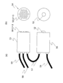
- the irradiation unit further converts infrared light having a different wavelength intensity distribution into LED (light emitting diode) or infrared LED and LD (laser diode) or
- emits is disclosed.
- the imaging unit may further include a CCD (Charge Coupled Device) image sensor, a CMOS (Complementary Metal Organic Semiconductor) image sensor, or an APD (Avalanche Photodiode) sensor.
- Solid-state imaging devices such as image dissectors, iconoscopes, image orthicons, vidicons, sachicons, planbicons, new biscones, new cosmicons, carnicons, trinicons, HARPs (High-gain Avalanche Rushing Amorphous).
- Imaging tube or imaging plate such as microchannel plate
- bolometer system imaging element such as MEMS (Micro Electro Mechanical System) bolometer, or A configuration using a pyroelectric imaging element is disclosed.
- the imaging device is preferably composed of a solid-state imaging device using a single element system such as Si or Ge, SiGe, InAs, InSb, PbS, PbSe, InGaAs, or HgCdTe.
- the imaging unit further discloses a configuration including a lens, a diaphragm, a filter, and the like.
- the color specification setting is to set in advance what color the brightness of the image is to display when displaying the image.
- the color setting can be set, for example, by setting the transmission timing of the image information or image signal, or by sequentially corresponding the image information or image signal to the reference trigger. Also, setting by separately generating color information or color setting signal, setting by superimposing color information or color setting signal on image information or image signal, setting by address in memory It can also be performed by setting or labeling or flagging in signal processing.
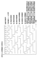
- an irradiation unit, an imaging unit, a color specification setting unit, and a control processing unit are provided, the imaging unit sends an imaging operation start signal to the control processing unit, and the control processing unit Based on the imaging operation start signal, an irradiation operation start instruction signal is sent to the irradiation unit, and further, a colorimetric setting operation start instruction signal is sent to the color specification setting unit, and the irradiation unit receives the irradiation operation start instruction signal
- the imaging unit irradiates the subject with infrared rays having different wavelength intensity distributions, and the imaging unit images the images of the subject by the infrared rays having different wavelength intensity distributions reflected by the subject.
- Image information to be represented is formed and sent to the color setting unit, and the color setting unit displays each of the images represented by the formed image information with different single colors based on the color setting operation start instruction signal. It discloses an image capturing apparatus according to claim to set the color specification information to the image information.
- information is a thing or the contents or state of a thing or a thing, and its notification.
- Information is preferably conveyed by signals. As such, information and signals may mean the same thing.
- an irradiation unit, an imaging unit, a color specification setting unit, and a control processing unit are provided, and the control processing unit sends an irradiation operation start instruction signal to the irradiation unit, and further starts an imaging operation.
- An instruction signal is sent to the imaging unit, a colorimetric setting operation start instruction signal is further sent to the colorimetric setting unit, and the irradiation unit applies infrared rays having different wavelength intensity distributions based on the irradiation operation start instruction signal.
- the image capturing unit captures images of the subject by infrared rays having different wavelength intensity distributions reflected by the subject based on the imaging operation start instruction signal, and represents image information representing each image.
- the color specification setting unit displays each of the images represented by the formed image information with different single colors based on the color setting operation start instruction signal. It discloses an image capturing apparatus according to claim to set the color specification information because the image information.
- the present invention further includes an irradiation unit, an imaging unit, a color specification setting unit, and a control processing unit, and the irradiation unit sends an irradiation operation start signal to the control processing unit, and further different wavelength intensity distributions.
- the control processing unit sends an imaging operation start instruction signal to the imaging unit based on the irradiation operation start signal, and further transmits a color setting operation start instruction signal to the color setting unit.
- the imaging unit captures images of the subject by infrared rays having different wavelength intensity distributions reflected by the subject, forms image information representing each image, and sends the image information to the color specification setting unit.
- the color setting unit sets color information for displaying each image represented by the formed image information with a different single color in the image information based on the color setting operation start instruction signal. It discloses an image capturing apparatus according to claim and.
- the present invention further includes an irradiation unit, an imaging unit, a color specification setting unit, and a control processing unit
- the color specification setting unit sends a color specification setting operation start signal to the control processing unit
- the control processing unit sends an irradiation operation start instruction signal to the irradiation unit based on the color specification setting operation start signal, further sends an imaging operation start instruction signal to the imaging unit, and the irradiation unit performs the irradiation operation.
- the subject Based on the start instruction signal, the subject is irradiated with infrared rays having different wavelength intensity distributions, and the imaging unit receives the respective infrared rays having different wavelength intensity distributions reflected by the subject based on the imaging operation start instruction signal.
- the image of the subject is captured and image information representing each image is formed and sent to the color specification setting unit.
- the color specification setting unit converts each of the images represented by the formed image information into different single colors.
- Yo The color specification information for color discloses an imaging apparatus and sets the image information.
- the image processing apparatus further includes a display unit, the control processing unit further sends a display operation start instruction signal to the display unit, and the display unit A configuration is disclosed in which, based on an operation start instruction signal, each of the images represented by the image information in which the color information is set is displayed in color according to the color information.
- the image processing unit further includes an image storage unit, and the control processing unit further sends an image storage operation start instruction signal to the image storage unit, and the image storage unit Discloses a configuration for storing the image information in which the color specification information is set based on the image storage operation start instruction signal.
- the image storage unit further starts the image storage operation using the image information set with the color specification information stored in the image storage unit.
- the display unit sends to the display unit based on the instruction signal, and the display unit receives the image information in which the color specification information is set and the color information stored in the image storage unit based on the display operation start instruction signal.
- a configuration is disclosed in which an image represented by image information in which color information that is one or both of the set image information is set is displayed in a color according to the color information.
- the separation irradiation unit further notifies the side that has transmitted the irradiation operation start instruction signal that the irradiation operation start instruction signal has been received.
- the imaging unit further notifies the side that has transmitted the imaging operation start instruction signal that the imaging operation start instruction signal has been received.
- the color specification specifying unit further notifies the side that has sent the color setting operation start instruction signal that the color setting operation start instruction signal has been received. Is preferred.
- control processing unit further notifies the imaging unit that the imaging operation start signal has been received.
- one or more of the irradiation operation start instruction signal, the imaging operation start signal, and the color specification setting operation start instruction signal are further transmitted by infrared rays. It is preferable to send.
- any one or more of the irradiation operation start instruction signal, the imaging operation start instruction signal, and the color specification setting operation start instruction signal are infrared rays. It is preferable to send by.
- any one or more of the irradiation operation start signal, the imaging operation start instruction signal, and the color setting operation start instruction signal are infrared rays. It is preferable to send.
- one or more of the irradiation operation start instruction signal, the imaging operation start instruction signal, and the color specification setting operation start signal are further infrared. It is preferable to send.
- a configuration is further disclosed in which one or more of the display operation start instruction signal and the image storage operation start instruction signal are transmitted by infrared rays.
- any one or more of various operation start signals and various operation start instruction signals be transmitted wirelessly.
- the irradiation unit may further superimpose the irradiation operation start signal on any one or a plurality of infrared rays having different wavelength intensity distributions. preferable.
- the imaging unit further includes a wavelength detection unit, and the wavelength detection unit is any one of the infrared rays having the different wavelength intensity distributions.
- the wavelength detection unit is any one of the infrared rays having the different wavelength intensity distributions.
- the imaging unit further includes an information generation unit, and generates a composite signal and / or a component signal from the imaging operation start signal and the image information. It is preferable.
- the control processing unit further includes an information separation unit, and the composite signal and / or the component signal are converted into the imaging operation start signal and the image information. It is preferable to separate any one or more.
- the component signal is a video signal or image information that can be used by decomposing the luminance signal, synchronization signal, and color signal that constitute the image
- the composite signal is the luminance signal, color signal, and synchronization that constitute the image. It is a composite synchronization signal or image information that combines signals so that even one signal line can be handled.
- the image conversion unit further includes an image conversion unit, and the image conversion unit is stored in the image information in which the color specification information is set and the image storage unit.
- An operation using any one or more of the four arithmetic operations of addition, subtraction, multiplication and division, exponential function, logarithmic function, and arbitrary function for any one or more of the image information set with the color specification information The structure which forms the image information or the image converted by applying is disclosed.
- the imaging unit further generates an imaging operation start signal, further includes an information generation unit, and the information generation unit includes the imaging operation start signal.
- separation was possible is disclosed.
- control processing unit further includes an information separation unit, and the information separation unit is configured to extract the imaging operation start signal and the image information from the composite information.
- separates any one or more of these is disclosed.
- the color specification setting unit further has a wavelength range or a center wavelength on the shortest wavelength side among images represented by the formed image information.
- Colorimetric information for coloring the first image captured by infrared rays having a wavelength intensity distribution by “R” is set to image information representing the first image, and the captured image other than the first image is captured.
- Disclosed is a configuration in which color information for displaying an image other than “R” is set in the formed image information other than the image information representing the first image.
- a separation unit, an imaging unit, and a color specification setting unit are provided, the separation unit separates light rays from a subject into infrared rays having different wavelength intensity distributions, and the imaging unit includes The image of the subject is captured by each of the infrared rays to form image information, and the color setting unit has a wavelength intensity distribution in which a wavelength range or a center wavelength is on the shortest wavelength side among the captured images Color information for color-representing the first image captured by infrared rays having R by “R” is set as image information representing the first image, and the captured image other than the first image is set as the image information Disclosed is an image photographing apparatus characterized in that color information for coloration other than “R” is set in the formed image information other than the image information representing the first image.
- the color specification setting unit has a wavelength intensity distribution in which a wavelength range or a center wavelength is on the shortest wavelength side in the captured image.
- Color information for displaying the first image captured by the first infrared by “R” is set to image information representing the first image, and the wavelength range or the center wavelength is next to the first infrared.
- Color information for color-coding a second image captured by infrared rays having a wavelength intensity distribution on the short wavelength side by “G” is set as image information representing the second image
- the first image and Disclosed is an image photographing apparatus characterized in that color information for color-coding the captured third image other than the second image by “B” is set to image information representing the third image. .
- a separation unit, an imaging unit, and a color specification setting unit are provided, the separation unit separates a light beam from a subject into light beams having different wavelength intensity distributions, and the imaging unit includes: The image of the subject is captured by the light beams having the different wavelength intensity distributions to form image information, and the color setting unit includes visible light having an “R wavelength region” among the captured images. And color information for displaying the first image captured by infrared rays having a wavelength intensity distribution closest to the “R wavelength region” by “R” is set as image information representing the first image, Colorimetric information for coloring the captured image other than the first image by colors other than “R” is set in the formed image information other than the image information representing the first image. Open the image capture device To.
- the color specification setting unit may include visible light having “R wavelength region” and “R wavelength region” in the captured image.
- the color information for displaying the first image captured by the first infrared ray having the closest wavelength intensity distribution by “R” is set to the image information representing the first image, and has the “G wavelength region”.
- Color information for displaying a second image captured by visible light and infrared light having a wavelength intensity distribution closest to the first infrared by “G” is set as image information representing the second image.
- the color information for expressing the captured third image other than the first image and the second image by “B” is set to image information representing the third image.
- the first image is further represented by “R”
- the second image is represented by “B”
- the third image is represented by “ It is preferable to display the color by “G”.
- the first image is further represented by “G”
- the second image is represented by “B”
- the third image is represented by “ You may color by “R”.
- the first image is further represented by “G”
- the second image is represented by “R”
- the third image is represented by “ The color may be represented by “B”.
- the first image is further represented by “B”
- the second image is represented by “R”
- the third image is represented by “ The color may be indicated by “G”.
- the first image is further represented by “B”
- the second image is represented by “G”
- the third image is represented by “ You may color by “R”.
- the predetermined color may be any one or more of a single color or primary color of “R”, “G”, and “B”, or It is preferable to use a suitable different single color or primary color, or a combination thereof.
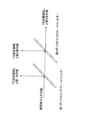
- the separation unit may further include one or more bandpass filters having different transmission wavelength intensity distributions or different reflection wavelength intensity distributions, one or more It is preferable to use one or a plurality of dichroic plate filters or one or a plurality of dichroic prism filters.
- the three-plate filter composed of dichroic prisms has three prisms, and each of the first and second dichroic prisms emits light by two internal reflections (a so-called Philips type dichroic prism), A compound prism (a so-called Sony type dichroic prism) that has a prism and emits from the first dichroic prism with two internal reflections and from the second dichroic prism with one internal reflection, three right triangular prisms and one isosceles A regular prismatic composite prism (so-called cascade type dichroic prism), a regular prismatic composite prism (so-called cross dichroic prism, or X Cube), and a two triangular pyramid and two quadrangular pyramid, and the like cubic composite prism (so-called Z cube) having an optical path of the three-dimensional and a bonding surface with Z-shaped edges.
- Philips type dichroic prism a so-called Philips type dichroic prism
- a compound prism a so-
- the separation portion is further configured using a glass filter, a plastic filter, a liquid crystal filter, or the like.
- the imaging unit further includes a plurality of pixels, and the separation unit is attached to each of the plurality of pixels. To do.
- the band-pass plate filter further has a lens shape.
- the entrance of the dichroic prism filter is formed into a lens shape.
- the imaging unit further includes a plurality of imaging units, and the start of the operations of the plurality of imaging units is synchronized.
- the start of the operations of the plurality of imaging units is further synchronized by Genlock or a similar means.
- any one of the above aspects it is preferable to shoot by cutting any one or more of ultraviolet rays, visible rays, and infrared rays.
- the image display device further includes a display unit, and the display unit displays each of the images represented by the image information in which the color specification information is set according to the color specification information.
- a configuration for displaying in color is disclosed.
- the display unit further color-codes each of the images represented by the image information in which the color specification information is set according to the color specification information. It is preferable to display the images at different times.
- the image capturing apparatus further discloses a configuration in which the display unit continuously displays the different images and displays a color image.
- the image capturing apparatus further discloses a configuration in which the display unit additively mixes the different images to display a color image.
- the image capturing apparatus further discloses a configuration in which the display unit subtractively mixes the different images to display a color image.
- the image capturing device may further include a light emitting display device such as a cathode ray tube monitor or a liquid crystal monitor, a transmissive display device or a reflective display device, or It is preferable that the printed material is composed of a printed material.
- a light emitting display device such as a cathode ray tube monitor or a liquid crystal monitor
- a transmissive display device or a reflective display device or It is preferable that the printed material is composed of a printed material.
- a cathode ray tube monitor or a liquid crystal monitor which is a display unit, displays a subject image based on image information in which color information is set, and a color image based on additive color mixing using “R”, “G”, and “B”. It is preferable to display.
- the display by printing displays the image of the subject by the image information in which the color information is set, and the color image by subtractive color mixture using “C”, “M”, and “Y”.
- an image storage unit is further provided, and the image storage unit discloses a configuration for storing image information in which the color specification information is set.
- the image storage unit is preferably configured using a video decoder, video encoder, FPGA, PLD, CPLD, DSP, SDRAM, field memory, frame memory, SAMPLE & HOLD circuit, latch circuit, or the like.
- the irradiating unit further discloses a configuration in which each of the infrared rays is irradiated with an intensity modulation with a phase difference.
- the irradiating unit further discloses a configuration in which each of the infrared rays is intensity-modulated at a different frequency to irradiate the subject.
- the irradiating unit further discloses a configuration in which each of the infrared rays is irradiated to the subject in a substantially different time range.
- any one of the above aspects it is preferable to modulate the intensity of infrared rays having different wavelength intensity distributions by causing one or more of LEDs and LD to emit light in a pulsed manner. .
- an infrared ray having a different wavelength intensity distribution is converted into a waveform such as a rectangular wave, a sine wave, a cosine wave, a triangular wave, a sawtooth wave, or a combined wave thereof. It is preferable that the intensity is modulated to a wave shape such as those waveforms having a duty ratio or a bias or a composite wave.
- any one of the above aspects it is preferable to irradiate a subject with infrared rays having different wavelength intensity distributions after intensity modulation with an open / close slit or a chopper.
- infrared rays having different wavelength intensity distributions that are intensity-modulated by adding a time difference to each single pulsed infrared ray irradiation of infrared rays having different wavelength intensity distributions. It is preferable to irradiate the subject.
- infrared rays having different wavelength intensity distributions which are modulated in phase by adding a time difference to each of a plurality of pulsed infrared irradiations of infrared rays having different wavelength intensity distributions, are used as subjects. Is preferably irradiated.
- the difference in phase between infrared rays having different wavelength intensity distributions having different wavelength intensity distributions and intensity modulated with phase differences is 0.1 second or less. Is preferred.
- infrared rays having different wavelength intensity distributions are formed by infrared LEDs and / or infrared lamps and infrared filters.
- the infrared filter examples include an infrared bandpass filter having various transmission wavelength bands, a combination of an infrared long wavelength transmission filter and an infrared short wavelength transmission filter.
- infrared rays having different wavelength intensity distributions by wavelength modulation or polarization modulation of infrared LEDs and / or infrared LDs.
- wavelength modulation and polarization modulation are preferably performed electromagnetically.
- the infrared LED and / or the infrared LD emit light in a wavelength range of about 750 nm to about 1200 nm.
- the infrared LED and / or the infrared LD emit light at a center wavelength in a wavelength range of about 750 nm to about 1200 nm.
- infrared rays having different wavelength intensity distributions are emitted by a plurality of infrared light sources.
- infrared rays having different wavelength intensity distributions are emitted by dividing one or more infrared light sources into a plurality of portions.
- the operation of the irradiation unit and the operation of the imaging unit start in synchronization.
- the operation of the irradiation unit, the operation of the imaging unit, and the operation of the color specification setting unit start in synchronization.
- the operation of the irradiation unit and the operation of the imaging unit start at a predetermined time interval.
- the operation of the irradiation unit, the operation of the imaging unit, and the operation of the color setting unit start at predetermined time intervals.
- the imaging unit further detects each of infrared rays having different wavelength intensity distributions that are intensity-modulated at different frequencies and reflected by the subject.
- a configuration for separately capturing images is disclosed.
- the operation of the irradiation unit and the operation of the imaging unit are periodically started at a frequency of 10 Hz or more.
- the operation of the irradiation unit, the operation of the imaging unit, and the operation of the color specification setting unit are periodically started at a frequency of 10 Hz or more. Is preferred. This is because, if different images are continuously displayed at a frequency of 10 Hz or more, it will appear as a color still image or a color moving image to the human eye.
- the display unit further includes image information in which the color specification information is set and the color specification information stored in the image storage unit.
- image information in which the color specification information is set
- the color specification information stored in the image storage unit A configuration is disclosed in which an image represented by image information in which color information that is one or both of the image information is set is displayed in a color according to the color information.
- the display unit further color-codes each image represented by the image information in which the color information is set according to the color information, and simultaneously A configuration to be displayed is disclosed.
- the operation of the irradiation unit, the operation of the imaging unit, the operation of the color specification setting unit, and the operation of the storage unit start in synchronization. It is preferable.
- the operation of the irradiation unit, the operation of the imaging unit, the operation of the color specification setting unit, and the operation of the storage unit are performed at predetermined time intervals. It is preferable to start.
- the irradiation unit, the imaging unit, the control processing unit, the color specification setting unit, the image storage unit, the image conversion unit, and the image It is preferable that any one or more of the display units are integrated.
- control processing unit the irradiation unit, the imaging unit, the color specification setting unit, the image storage unit, the image conversion unit, and the image It is preferable that any one or more of the display units are on-chip.
- Any one or more of the display units further includes a density adjustment unit, and the density adjustment unit is set with the image information in which the color specification information is set and the color specification information stored in the image storage unit. It is preferable to adjust one or more of lightness or density, contrast, and gamma correction parameters of any one or more of the image information and the converted image information.
- the color specification setting unit or the control processing unit includes an RGB video signal, an NTSC video signal, a PAL video signal, a SECAM video signal, and other composites.
- a signal output unit that outputs one or more of a video signal, a YC separation signal, an S video signal, an SDI signal, other component video signals, an MPEG digital video signal, an Ethernet video signal, and other digital video signals; It is preferable to provide.
- any one or more of the irradiation unit, the imaging unit, the color specification setting unit, and the control processing unit is an RGB video signal, NTSC.
- Video signals, PAL video signals, SECAM video signals, other composite video signals, YC separation signals, S video signals, SDI signals, other component video signals, MPEG digital video signals, Ethernet video signals, and other digital video signals It is preferable to output one or more of the above.
- the subject is irradiated with infrared rays having different wavelength intensity distributions and the infrared rays have different wavelength intensity distributions reflected by the subject.
- An image photographing method is disclosed, in which image information representing each image is formed by capturing the images, and each of the images represented by the formed image information is represented by different single colors.
- a first image captured by infrared rays having a wavelength intensity distribution having a wavelength range or center wavelength on the shortest wavelength side is “R”. And displaying the captured image other than the first image with a color other than “R”.
- a first image captured by a first infrared ray having a wavelength intensity distribution having a wavelength range or center wavelength on the shortest wavelength side among the captured images is further described as “ R ”, and a second image captured by the second infrared having a wavelength intensity distribution whose wavelength range or center wavelength is on the short wavelength side next to the first infrared is represented by“ G ”.
- the second image is further represented by “B”, and images other than the first image and the second image are represented by “G”. It is preferable to color.
- the different single color may be one or more of “R”, “G”, and “B”, or an appropriate different single color or It is preferable to use primary colors and combinations thereof.
- the first image is further represented by “R”, and the captured image other than the first image is represented by “G” and “ It is preferable that the color is represented by any one or a plurality of “B”, or an appropriate different single color or primary color, or a combination thereof.
- the different single color or primary color may be any one or more of “C”, “M”, and “Y”, or may be appropriately different. It is preferable to use a single color or primary color, or a combination thereof.
- an appropriate two monochromatic, two primary colors or “R”, “G”, and “B” obtained by additively mixing the color-coded image. It is preferable to form a color image according to any two of the above.
- an appropriate two single color, two primary colors or “C”, “M”, and “Y” obtained by subtractively subtracting the color-coded image from each other. It is preferable to form a color image according to any two of the above.
- any one of the above aspects according to an appropriate three monochromatic color, primary color, or “R”, “G”, and “B” obtained by additive color mixing of the color-coded image. It is preferable to form a color image.
- the color image is further subtracted and mixed by appropriate three single colors, three primary colors, or “C”, “M”, and “Y”. It is preferable to form a color image.
- the RGB color image is further converted into a converted color image by RGBB color, index color, CMY color, CMYK color, or other different color display. It is preferable.
- any one of four arithmetic operations of addition, subtraction, multiplication, and division, an exponential function, a logarithmic function, and an arbitrary function is further added to the image.
- the captured image, the captured image, a two-color or two-primary color image, a three-color or three-primary color image, an RGB color It is preferable to store one or more of an image, a CMY color image, a converted image, and a converted color image.
- the captured image, the captured image, a two-color or two-primary color image, a three-color or three-primary color image, an RGB color It is preferable to display one or more of an image, a CMY color image, a converted image, and a converted color image.
- the color-coded image, two-color or two-primary color image, three-color or three-primary color image, RGB color image, or converted It is preferable to adjust one or more of color balance, hue, brightness or density, contrast, and gamma correction parameters of one or more colors of the image and the converted color image, respectively.
- any one of the above aspects it is preferable to irradiate a subject with infrared rays having two, three, four or more different wavelength intensity distributions.
- each of infrared rays having different wavelength intensity distributions is subjected to intensity modulation with a phase difference and irradiated to the subject.
- the infrared light having the different wavelength intensity distribution is further subjected to intensity modulation at a different frequency to irradiate the subject.
- the subject is irradiated with infrared rays having different wavelength intensity distributions in different time ranges. That is, it is preferable that the respective infrared rays are not irradiated substantially simultaneously.
- the irradiation operation and the imaging operation are further started in synchronization.
- the irradiation operation, the imaging operation, and the color specification execution are started in synchronization.
- infrared rays from a subject are separated into infrared rays having different wavelength intensity distributions, and images of the subject are picked up by the respective infrared rays having different wavelength intensity distributions.
- the first image captured by infrared rays having a wavelength intensity distribution with the wavelength range or the center wavelength being on the shortest wavelength side is represented by “R”, and the captured image other than the first image is displayed.
- An image photographing method is disclosed in which the color is represented by colors other than “R”.
- a first image captured by a first infrared ray having a wavelength intensity distribution having a wavelength range or center wavelength on the shortest wavelength side is “R”.
- the second image captured by the second infrared having a wavelength intensity distribution having a wavelength range or center wavelength on the short wavelength side next to the first infrared is colored by “G”, and the first An image photographing method is disclosed in which an image other than the image and the second image is represented by “B”.
- the second image is further represented by “B”, and images other than the first image and the second image are represented by “G”. It is preferable to color.
- the subject may be irradiated with infrared rays having one wavelength intensity distribution and infrared rays having two or more different wavelength intensity distributions. preferable.
- the irradiation operation and the imaging operation are further started in synchronization.
- the irradiation operation, the imaging operation, and the color specification execution are started in synchronization.
- light rays from a subject are separated into light rays having different wavelength intensity distributions, and images of the subject are picked up by the respective light rays having different wavelength intensity distributions.
- the first image captured by visible light having an “R wavelength region” and infrared light having a wavelength intensity distribution closest to the “R wavelength region” is represented by “R”.
- Disclosed is an image photographing method characterized in that the picked-up image other than is color-coded by means other than “R”.
- a visible ray having an “R wavelength region” and a first infrared ray having a wavelength intensity distribution closest to the “R wavelength region” are captured.
- the first image is represented by “R”
- the second image captured by the visible light having “G wavelength region” and the second infrared having a wavelength intensity distribution close to the first infrared is represented by “G”.
- an image photographing method is disclosed, in which an image other than the first image and the second image is represented by “B”.
- the second image is further represented by “B”, and images other than the first image and the second image are represented by “G”. It is preferable to color.
- a subject is further irradiated with light rays having one, two, or three or more different wavelength intensity distributions.
- a light beam having the different wavelength intensity distribution is further subjected to intensity modulation with a phase difference and irradiated onto the subject.
- each of the light beams having different wavelength intensity distributions is subjected to intensity modulation at different frequencies to irradiate the subject.
- any one of the above aspects it is disclosed to irradiate the subject with light beams having different wavelength intensity distributions in different time ranges. That is, it is preferable that the respective infrared rays are not irradiated substantially simultaneously.
- the irradiation operation and the imaging operation are further started in synchronization.
- the irradiation operation, the imaging operation, and the color specification execution are started in synchronization.
- the captured image is preferably displayed in a color.
- the captured image is preferably stored.
- the captured image and the stored image are color-coded and displayed simultaneously.
- one or both of the captured image and the stored image may be color-coded and displayed in different time ranges. preferable.
- the light beam from the subject may be either a light beam reflected by the subject, a light beam transmitted through the subject, or a light beam emitted from the subject, or It is preferable that there is a plurality.
- the light beam or light includes one or more of ultraviolet rays, visible rays, and infrared rays.
- any one of the above aspects it is preferable to use one or more of ultraviolet rays, visible rays, and infrared rays.
- any one of the above aspects it is preferable to use light rays from space such as stars and nebulae.
- an incandescent lamp in any one of the above aspects.
- any one of the above aspects it is preferable to further use a fluorescent light beam.
- any one of the above aspects it is preferable to use ultraviolet rays, visible rays, or infrared rays as bias light.
- the color CCD camera as the imaging unit is further used during the day and the monochrome CCD camera as the imaging unit is used at night.
- the switching is preferably performed based on measuring brightness using a light detection element, an illuminance meter, a solar cell, or the like.
- a monochrome CCD camera as the imaging unit both in the daytime and at night.
- a color CCD camera as the image pickup unit for both daytime and nighttime.
- a color CCD camera as the imaging unit using infrared illumination at night.
- the color CMOS camera as the imaging unit is further used during the day and the monochrome CMOS camera as the imaging unit is used at night.
- the switching is preferably performed based on measuring the brightness with a light detection element, an illuminance meter, a solar cell, or the like.
- CMOS camera that is the imaging unit for both daytime and nighttime.
- CMOS camera as the imaging unit both in the daytime and at night.
- the infrared cut filter is used during the day and the infrared cut filter is not used at night.
- the switching is preferably performed based on measuring the brightness with a light detection element, an illuminance meter, a solar cell, or the like.
- RGB components are combined into one as in an NTSC video signal. It is preferable to collectively form one image.
- any one of the above aspects it is preferably used for monitoring or security of a night vision camera or the like.
- any one of the above aspects it is preferably used as night vision goggles or night vision glasses.
- the color image display may be performed in a monochrome image display.
- a plurality of irradiation units may be fixedly installed at a plurality of locations, and image capturing may be performed using an imaging unit and a color setting unit integrated so as to be portable. Good.
- the irradiating unit appears to be independent, but an image capturing unit, a color setting unit, a control processing unit, and the like are separately required for image capturing according to the present invention.
- the irradiation unit, the imaging unit, the color setting unit, the control processing unit, etc. can be used indoors such as a ceiling, or in a vehicle such as an automobile, train, ship or airplane. It may be installed on the ship or in the cabin.
- an irradiation unit, an imaging unit, a color specification setting unit, a control processing unit, etc. may be installed on a pillar used for a streetlight, a signboard, a traffic light, etc. Good.
- an irradiation unit, an imaging unit, a color specification setting unit, a control processing unit, and the like may be installed in a building such as a house or a building.
- an irradiation unit, an imaging unit, a color specification setting unit, a control processing unit, and the like may be further incorporated in the fluorescent lamp.
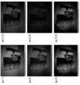
- the subject is provided with an adherent member that reflects infrared rays having a predetermined wavelength intensity distribution, and the subject is colored by imaging the infrared rays reflected by the subject. It is preferable to obtain an image.
- an infrared ray is irradiated on a subject including an adherent member that reflects infrared rays having a predetermined wavelength intensity distribution, and the infrared ray reflected by the subject is imaged.
- a color image of the subject that is the same as or approximate to the color of the subject under white light in the visible light range.
- an irradiation unit irradiates a subject with infrared rays
- the separation unit emits infrared rays reflected by the subject. Separating the infrared rays having different wavelength intensity distributions, the image pickup unit picks up an image of the subject by each infrared ray and forms image information, and the color setting unit sets the formed image information
- an image photographing apparatus characterized in that color information for representing each represented image with a different single color is set in the image information.
- a separation unit, an imaging unit, and a color specification setting unit are provided, the separation unit separates light rays from a subject into light rays having different wavelength intensity distributions, and the imaging units are respectively
- the image of the subject is captured by the light beams having the different wavelength intensity distributions to form image information
- the color specification setting unit is configured to color each of the images represented by the formed image information with different single colors.
- the image photographing apparatus is characterized in that the color information is set in the image information.
- image information representing each image obtained by separating infrared rays from a subject into infrared rays having different wavelength intensity distributions and capturing images of the subjects with the respective infrared rays having different wavelength intensity distributions is characterized in that each of the images represented by the formed image information is represented by different single colors.
- the subject is irradiated with infrared rays, the infrared rays reflected by the subject are separated into infrared rays having different wavelength intensity distributions, and each of the infrared rays having different wavelength intensity distributions
- an image photographing method characterized in that images are captured to form image information representing the respective images, and each of the images represented by the formed image information is represented by different single colors.
- a light beam from a subject is separated into light beams having different wavelength intensity distributions, and images of the subject are captured by respective infrared rays having different wavelength intensity distributions to represent the respective images.
- an image photographing method characterized in that image information is formed and each of the images represented by the formed image information is represented by different single colors.
- light rays from a subject are separated into light rays having different wavelength intensity distributions, images of the subject are picked up by the respective light rays having different wavelength intensity distributions, and the picked-up images Among them, a first image captured by visible light having “R wavelength region” and infrared light having a wavelength intensity distribution closest to the “R wavelength region” is represented by “R”, and “B wavelength region” is defined.
- a second image captured by an infrared ray having a wavelength intensity distribution closest to the “R wavelength region” and an infrared ray having a wavelength intensity distribution closest to the “R wavelength region” is represented by “B”, and the first image and An image capturing method is provided, wherein the captured image other than the second image is color-coded by “G”.
- an image photographing method characterized in that a color image that is the same as or approximate to the color of a subject under white light in a visible light region is obtained from an image captured by infrared rays from the subject. provide.
- a color image that is the same as or similar to the color of a subject under white light in the visible light range is captured by an infrared image that is reflected by the subject by irradiating the subject with infrared rays.
- An image capturing method is provided.
- an infrared image reflected on the human skin by irradiating the human skin with an infrared color image that is the same as or similar to the color of the human skin under white light in the visible light range.
- An image capturing method is provided, which is obtained from an image captured by the method.
- the imaging unit further includes a silicon image sensor, and a color image that is the same as or approximate to the color of the subject under white light in the visible light region is captured by infrared rays from the subject.
- the imaging unit further includes a silicon image sensor, and irradiates the subject with infrared light on a color image that is the same as or similar to the color of the subject under white light in the visible light range, and the subject
- An image photographing apparatus is provided, which is obtained from an image picked up by infrared rays reflected by the light.
- a separation unit, an imaging unit, and a color specification setting unit are provided, the separation unit separates a light beam from a subject into light beams having different wavelength intensity distributions, and the imaging unit further includes: A silicon image sensor that captures images of the subject with light beams having different wavelength intensity distributions to form image information, and the color specification setting unit includes a most visible light region of the captured images.
- a first image captured by infrared light having a wavelength distribution close to 1 is represented by “R”, and the infrared light having a wavelength distribution close to the visible light region is next to the wavelength distribution of the infrared light used for capturing the first image.
- the captured second image is represented by “B”
- the third image captured by infrared light having a wavelength distribution close to the visible light region next to the wavelength distribution of infrared light used for capturing the second image is represented by “ By "G”
- a subject having an adherent member that reflects infrared rays having a predetermined wavelength intensity distribution is irradiated with infrared rays, and the color of the subject is obtained from an image captured by infrared rays reflected by the subject.
- an image photographing method characterized by obtaining an image.
- a subject having an adherent member that reflects infrared rays having a predetermined wavelength intensity distribution is irradiated with infrared rays, and an image captured by the infrared rays reflected by the subject is more visible.
- an image photographing method characterized by obtaining a color image of the subject that is the same as or similar to the color of the subject under white light.
- the image photographing device and the image photographing method of the present invention it is possible to form a more natural color image of a subject in infrared rays.
- the color image obtained by the image capturing apparatus and the image capturing method according to the present invention has a large amount of information. Yes. For this reason, as one effect, a more natural and easy-to-view color image can be provided.
- FIG. 1 is a schematic diagram of a configuration of an image capturing device according to an embodiment of the present invention. It is a schematic diagram of the structure of the image imaging device which concerns on another one Embodiment of this invention. It is a figure which shows the relationship of the wavelength of the infrared rays in one Embodiment of this invention, an ultraviolet-ray, and visible light. In one Embodiment of this invention, it is an example figure of wavelength intensity distribution at the time of using three infrared LED which radiates
- FIG. 1 is a schematic diagram of a configuration of Embodiment 1 of an image capturing device and an image capturing method according to the present invention. It is a timing chart in Example 1 of an image photographing device and an image photographing method according to the present invention. It is a timing chart in Example 1 of the imaging device and method by this invention.
- Example 2 of the image capturing device and the image capturing method according to the present invention It is a timing chart in Example 2 of the imaging device and method by this invention. It is a timing chart in Example 2 of the imaging device and method by this invention. It is a schematic diagram of a structure of Example 3 of the image capturing device and the image capturing method according to the present invention. It is a schematic diagram of a structure of Example 4 of the image capturing device and the image capturing method according to the present invention. It is an example figure of the reflective characteristic of the 1st and 2nd dichroic plate filter of Example 4 of the imaging device by the present invention and the imaging method.
- Example 5 It is a schematic diagram of a structure of Example 5 of the image capturing device and the image capturing method according to the present invention. It is a schematic diagram of a structure of Example 6 of the image capturing device and the image capturing method according to the present invention. It is a schematic diagram of a structure of Example 7 of the image capturing device and the image capturing method according to the present invention. It is a schematic diagram of a structure of Example 8 of the image capturing device and the image capturing method according to the present invention. It is a schematic diagram of a structure of Example 9 of the image capturing device and the image capturing method according to the present invention. It is the photograph by Experimental example 1 which concerns on one Embodiment of this invention.
- An image capturing apparatus includes an irradiation unit and an imaging unit.
- the irradiation unit irradiates the subject with infrared rays having different wavelength intensity distributions.
- infrared rays having different wavelength intensity distributions mean infrared rays having different wavelength ranges or center wavelengths.
- the imaging unit captures an infrared image of the subject with each infrared ray having a different wavelength intensity distribution reflected by the subject.
- the wavelengths of infrared rays irradiated by the irradiation unit are ⁇ 1, ⁇ 2, and ⁇ 3.
- the imaging unit forms an infrared ray reflected from the subject and having a wavelength of ⁇ 1 on an imaging surface for imaging an optical image such as a CCD image sensor, and an in-plane intensity distribution of the infrared ray having a wavelength of ⁇ 1 on the imaging surface.
- This in-plane intensity distribution is called an object image or infrared image by infrared rays having a wavelength of ⁇ 1.
- such an in-plane intensity distribution can be expressed by a two-dimensional distribution function.
- the intensity of infrared rays having a wavelength of ⁇ 1 in a certain section in the imaging surface having the center or center of gravity position (x, y) is represented by I1 (x , Y).
- the imaging unit forms an infrared ray having a wavelength of ⁇ 2 reflected from the subject on the imaging surface, and acquires an in-plane intensity distribution of the infrared ray having a wavelength of ⁇ 2 on the imaging surface.
- the intensity of infrared light having a wavelength of ⁇ 2 at the position (x, y) is represented as I2 (x, y).
- the imaging unit forms an infrared ray having a wavelength of ⁇ 3 reflected from the subject on the imaging surface, and acquires an in-plane intensity distribution of the infrared ray having a wavelength of ⁇ 3 on the imaging surface.
- the intensity of the infrared ray having the wavelength of ⁇ 3 at the position (x, y) is represented as I3 (x, y).
- I1 (x, y), I2 (x, y), I3 (x, y), and the like can be displayed as two-dimensional array data.
- I1 (x, y), I2 (x, y), I3 (x, y), and the like can be displayed as two-dimensional array data.
- the imaging unit may acquire I1 (x, y), I2 (x, y), and I3 (x, y) at the same time, or may acquire them at different times. For example, by simultaneously irradiating infrared rays having wavelengths of ⁇ 1, ⁇ 2, and ⁇ 3 and separating the infrared rays of the respective wavelengths with a filter, I1 (x, y), I2 (x, y), and I3 (x, y) are obtained. Can be acquired at the same time.
- I1 (x, y), I2 (x, y), and I3 (x, y) can be sequentially acquired at different times.
- the infrared image corresponds to the in-plane intensity distribution of colorless infrared rays on the imaging surface
- a display device such as a liquid crystal display device according to the intensity, monochrome, mono color or pseudo color according to the infrared intensity Is displayed.
- the infrared wavelength when the infrared wavelength is different, the infrared reflectance of the subject is different.
- I1 The values of x, y), I2 (x, y) and I3 (x, y) will be different. Therefore, the values of I1 (x, y), I2 (x, y), and I3 (x, y) are made to correspond to different monochromatic lightness / density according to a certain natural law, respectively, under the visible light of the subject. It is one of the objects of the present embodiment to reproduce the color at and to obtain a color image of the subject.
- Various methods for expressing colors are known. For example, when a color is expressed by the brightness of each of “R”, “G”, and “B”, the value of I1 (x, y) is the brightness of the “R” component, and the value of I2 (x, y) is By assuming that the value of I3 (x, y) is proportional to the brightness of the “G” component and the brightness of the “B” component, respectively, and by adding and mixing each brightness obtained by setting an appropriate proportionality coefficient, , The color in the section at position (x, y) is determined. A color image can be obtained by determining the color in each section across the plane.
- G ⁇ I2 (x, y) (2)
- B ⁇ I3 (x, y) (3)
- ⁇ , ⁇ , and ⁇ are proportional coefficients for converting each of the infrared intensities I1 (x, y), I2 (x, y), and I3 (x, y) into R, G, and B, respectively. It is.
- the color of a certain section in the display screen is expressed by equations (1) to (3).
- This is sometimes referred to as color expression according to the information represented by the equations (1) to (3), and ⁇ , ⁇ and ⁇ may be referred to as color information.
- R, G, and B in the equations (1) to (3) may be referred to as image information in which color specification information is set.
- the value of I1 (x, y) corresponds to the lightness of “R”
- the value of I2 (x, y) corresponds to the lightness of “G”
- the value of I3 (x, y) corresponds to the lightness of “B”.
- the previous I1 (x, y) value corresponds to the lightness of “R”, the value of I2 (x, y) corresponds to the lightness of “G”, and the value of I3 (x, y) corresponds to the lightness of “B”.
- (R, G, B) ( ⁇ 1I1 (x, y), ⁇ 2I2 (x, y), ⁇ 3I3 (x, y))
- ( ⁇ I1 (x, y), ⁇ I2 (x, y), ⁇ I3 (x, y)) (9) Can be expressed.
- Expression (8) or (9) is expressed in the same way as Expressions (1) to (3) in another form.
- Expressions (1) to (3) in another form.
- this corresponds to the case where the off-diagonal term on the right side of Equation (6) is not zero. .
- the number and size of a certain section in the imaging surface and a certain section in the display screen can be variously set. However, the larger the number of sections or the smaller the size, the higher the resolution or resolution of the image. Get better.
- color information is set in the image information, so that the image information can be displayed as a color image and reproduced by printing or the like.
- the brightness of “R” mainly depends on the value of I1 (x, y), that is, on the right side of Equation (6), it is compared with the diagonal term.
- the inventors of the present application have found that when the off-diagonal term is made small or almost zero, the color of the subject under visible light can be reproduced well.
- the brightness of the “R” component of the image information for which the color information is set depends mainly on the value of I1 (x, y), and that an infrared image having a wavelength of ⁇ 1 is represented by “R”. There is a case to do. The same applies to the “G” component and the “B” component.
- FIG. 1 shows a configuration of an image photographing apparatus according to an embodiment of the present invention.
- the image capturing apparatus includes an irradiation unit 1, an imaging unit 2, and a color specification setting unit 3.
- the irradiation unit 1 irradiates the subject 4 with infrared rays 5 having different wavelength intensity distributions.
- the imaging unit 2 captures an image of the subject 4 with each of the infrared rays 6 having different wavelength intensity distributions reflected by the subject 4, and forms image information 7 representing each image.
- the color specification setting unit 3 sets color information for displaying each of the images represented by the formed image information 7 with different single colors in the image information 7.
- the infrared rays 5 having different wavelength intensity distributions may be irradiated at different times so that the infrared rays having the respective wavelength intensity distributions are not irradiated substantially simultaneously.
- the time length is shorter than the time length of the infrared rays having one wavelength intensity distribution. Is also short.
- the infrared rays 5 having different wavelength intensity distributions may be irradiated simultaneously. In this case, the reflected infrared rays 6 having different wavelength intensity distributions are separated using a filter or the like.
- the infrared rays 5 having different wavelength intensity distributions may be irradiated simultaneously, the infrared rays 5 having different wavelength intensity distributions may be irradiated to the subject 4 with intensity modulation at different frequencies.
- the reflected infrared rays 6 having different wavelength intensity distributions are separated by detecting and separating each of the infrared rays 6 having different wavelength intensity distributions that are modulated at different frequencies and reflected by the subject 4. Is done.
- an analog signal or a digital signal may be used, and information representing each image is stored and transmitted in a separable manner.
- signal information related to display timing such as image brightness information or luminance information and brightness information start position, imaging start time, and screen vertical synchronization.
- the header information of the image information 7 may include information indicating the start position and size of information representing each image.
- Each image represented by the image information 7 indicates the intensity distribution of the reflected infrared rays 6. For this reason, if each image represented by the image information 7 is displayed as it is on a display or printing, it is displayed in a single color or a mono color.
- the single color means that it is expressed by the brightness / density of only one color. For example, a position where the intensity of the reflected infrared ray 6 is high is expressed by bright red, and a position where the intensity of the infrared ray 6 is weak is expressed by dark red. In this case, a monochromatic expression in red is obtained. Therefore, a single color image can be obtained by setting in the image information 7 information indicating which color of each image represented by the image information 7 is to be expressed.
- images obtained as a result of irradiating a subject with first, second, and third infrared rays having three different wavelength intensity distributions are defined as a first image, a second image, and a third image, respectively.
- the color information may indicate that a single color of a different color is used for each image without designating which color of the single color to express.
- a plurality of images may be represented by a single color of the same color.
- the color specification information may indicate that the first image and the third image are expressed by a single color of the same color, and the second image is expressed by a single color of a different color. The information content of the color information can be changed later.
- the color information when the color information is set in the image information 7 by the color setting unit 3, that is, the color setting is performed, the color of the brightness of the image is displayed in advance when the image is displayed.
- the color information can be set by superimposing the color setting information on the image information 7, set by an address in the memory, or set by labeling or flagging in signal processing. Embedding can also be performed by including color specification information as part of the header information of the image information 7.
- FIG. 2 is a diagram illustrating a configuration of an image capturing device according to another embodiment of the present invention.
- the present invention further includes a display unit 9, and the display unit 9 displays each of the different images according to the image information 8 in which the color information is set by using a predetermined color. Also good. That is, the image photographing device according to the present embodiment further includes the display unit 9 in the image photographing device according to the above-described embodiment.
- the display unit 9 displays each of the images represented by the image information 7 in the expression specified by the color information by the image information 8 formed by setting the color information to the image information 7.
- they may be displayed on the display unit 9 at the same time, or may be displayed at different times.
- the display unit 9 uses a predetermined single color, for example, “R”, “G”, and “B”, based on the image information 8, and the subject imaged by each infrared ray having a different wavelength intensity distribution. If different images are displayed in color and continuously displayed at high speed, an RGB color image is apparently displayed.
- the image capturing apparatus may further include an image storage unit 10.
- the image storage unit 10 may store the image information 8.
- the display unit 9 may display either one or both of the image information 8 and the image information 11 stored in the image storage unit 10.
- the displayed image is displayed according to the color information set in the image information 8 or the image information 11.
- you may display according to the color information different from the color information set to image information, such as displaying the image information 11 according to the color information set to the image information 8.
- FIG. the image information 8 or the image information 11 may be displayed in color according to the color information newly set by the user or the like.
- the display unit 9 may simultaneously display a total of three images from one or both of the image information 8 and the image information 11. In that case, if the display unit 9 simultaneously displays images included in the image information using predetermined colors, for example, “R”, “G”, and “B”, an RGB color image can be displayed.
- FIG. 3 shows a configuration of an image capturing apparatus according to another embodiment of the present invention.
- the image apparatus includes an irradiation unit 1, an imaging unit 2, a color specification setting unit 3, and a control processing unit 12.
- the imaging unit 2 sends an imaging operation start signal 13 to the control processing unit 12.
- the control processing unit 12 Based on the imaging operation start signal 13, the control processing unit 12 sends an irradiation operation start instruction signal 14 to the irradiation unit 1, and further sends a color setting operation start instruction signal 15 to the color setting unit 3.
- the irradiation unit 1 irradiates the subject 4 with infrared rays 5 having different wavelength intensity distributions based on the irradiation operation start instruction signal 14, and the imaging unit 2 reflects the reflected infrared rays 6 having different wavelength intensity distributions reflected by the subject 4.
- Images of the subject 4 are captured, and image information 7 representing each image is formed and sent to the color setting unit 3.
- the color setting unit 3 sets color information in the image information 7 based on the color setting operation start instruction signal 15.
- the image apparatus may further include a display unit 9.
- the control processing unit 12 further sends a display operation start instruction signal 16 to the display unit 9, and the display unit 9 is represented by the image information 8 in which the color information is set based on the display operation start instruction signal 16.
- Each image to be displayed may be displayed in a color according to the color information.
- the image apparatus may further include an image storage unit 10.
- the control processing unit 12 further sends an image storage operation start instruction signal 17 to the image storage unit 10, and the image storage unit 10 may store the image information 8 based on the image storage operation start instruction signal 17. Good.
- the image storage unit 10 further displays the image information 11 in which the color information stored in the image storage unit 10 is set based on the image storage operation start instruction signal 17. Based on the display operation start instruction signal 16, the display unit 9 may display one or more of the image information 8 and the image information 11 in a color according to the color information.
- the color specification setting unit 9 “R” a first image captured by infrared rays having a wavelength intensity distribution having a wavelength range or center wavelength on the shortest wavelength side among the images represented by the formed image information. Is set to image information representing the first image, and the color information used to color a captured image other than the first image using a color other than “R” is set to the first image. If it is set to the formed image information other than the image information representing, it is possible to display a color close to that of a captured image by visible light.
- the irradiation unit 1 can form image information suitable for moving image display by irradiating the subject 4 with intensity modulation of each of the infrared rays 5 with a phase difference.
- the irradiation unit may irradiate the subject 4 by modulating the intensity of each of the infrared rays 5 at different frequencies.
- the irradiation unit 1 irradiates the subject 4 with the infrared rays 5 so that each of the infrared rays 5 is not irradiated substantially simultaneously, the color separation is improved.
- the display unit 9 further displays each of the images represented by any one of the image information 8 in which the color information is set and the image information 11 in which the color information stored in the image storage unit 10 is set according to the color information. When color is displayed and displayed at the same time, flicker is reduced.
- the subject is irradiated with infrared rays having different wavelength intensity distributions, and images of subjects with different infrared intensity distributions reflected by the subjects are captured to form image information representing the respective images.
- image information representing the respective images.
- Each of the images represented by the image information may be represented by different single colors.
- the first image captured with infrared rays having a wavelength intensity distribution having a wavelength range or center wavelength on the shortest wavelength side is represented by “R”, and other than the first image
- the captured image may be represented by a color other than “R”.
- different single colors may be combined colors of two or more of “R”, “G”, and “B”.
- FIG. 4 shows an example in which infrared rays having different wavelength intensity distributions are composed of three different wavelength distributions. Infrared rays having different wavelength intensity distributions may be composed of two or four or more different wavelength intensity distributions.
- Infrared rays having different wavelength intensity distributions may be partially overlapped with each other as shown in FIG. Alternatively, there may be no overlap. Further, the different wavelength intensity distributions may have a rectangular wave shape, a Gaussian distribution shape, or a Lorentz distribution shape. Alternatively, it may have a distribution shape, asymmetric distribution, or arbitrary distribution shape.
- FIG. 4 also shows the wavelength relationship with ultraviolet light and visible light, but infrared light is located on the longer wavelength side than visible light.
- the visible rays of purple, blue, green, and red are generally indicated as “V”, “B”, “G”, and “R”, respectively, and ultraviolet rays and infrared rays are indicated as “UV” and “IR”, respectively. And generally displayed.
- X-rays are located on the shorter wavelength side than ultraviolet rays.
- Radio waves such as microwaves are located on the longer wavelength side than infrared rays.
- Infrared rays or wavelength-modulated infrared rays having such different wavelength intensity distributions are infra-red lamps such as incandescent lamps and other infrared lamps that emit infrared light such as plasma light emission and infrared LED (light emitting diode). It can be generated by a path filter. Moreover, you may produce
- the infrared bandpass filter examples include an infrared bandpass filter having various transmission wavelength bands and a combination of a long wavelength transmission filter and a short wavelength transmission filter.
- a wavelength selective liquid crystal filter or the like may be used.
- a heating element such as an incandescent lamp, a plasma emitting light such as a fluorescent lamp, an infrared lamp emitting infrared rays such as an infrared LED, and a wavelength selective liquid crystal filter with a shutter function may be used.
- intensity modulation may be performed by an open / close slit, a chopper, or a shutter.
- infrared rays having different wavelength intensity distributions may be formed by using a plurality of LEDs or infrared LEDs that emit infrared rays having different wavelength intensity distributions.
- FIG. 5 shows an example of the wavelength intensity distribution when three infrared LEDs emitting infrared rays having different wavelength intensity distributions are used.
- infrared rays having different wavelength intensity distributions may be formed by using a plurality of LDs (laser diodes) or infrared LDs that emit light beams having different wavelengths.
- FIG. 6 shows an example in which three infrared LDs that emit infrared rays having different wavelength intensity distributions are used. Since the infrared LD has a narrow emission wavelength range, the wavelength intensity distributions generally do not overlap as shown in FIG.
- infrared LED and infrared LD may be combined.
- the intensity may be modulated by blinking the infrared LED or infrared LD.
- the intensity modulation may be performed by causing the infrared LED or the infrared LD to emit light while being changed in pulses in time.
- infrared LED or infrared LD wave shape such as rectangular wave, sine wave, cosine wave, triangular wave, sawtooth wave, their combined wave, their waveform with duty ratio and bias or wave shape such as synthetic wave
- the intensity may be modulated.
- the intensity of emitted light may be modulated by changing the power supplied to the infrared LED or the infrared LD.
- intensity modulation may be performed by apparently blinking using an open / close slit, chopper, or liquid crystal shutter.
- infrared rays having different wavelength intensity distributions may be formed by wavelength-modulating infrared LEDs or infrared LDs.
- the wavelength modulation may be performed electromagnetically. Further, intensity modulation may be performed.
- infrared rays having different wavelength intensity distributions may be generated by a plurality of infrared light sources.
- infrared rays having different wavelength intensity distributions may be generated by dividing one or more infrared light sources into a plurality of pieces.
- a solid-state imaging device using a single element system such as Si or Ge, SiGe, InAs, InSb, PbS, PbSe, InGaAs, or HgCdTe can be used.
- the long wavelength side of the sensitivity wavelength region of Si is up to around 1200 nm. Therefore, infrared rays having different wavelength intensity distributions may be generated from about 750 nm to about 1200 nm.
- or infrared LD can be light-emitted also in the wavelength range in the wavelength range of about 750 nm to about 1600 nm. Therefore, when infrared rays or LDs emit light in the wavelength range of about 750 nm to about 1200 nm to generate infrared rays having different wavelength intensity distributions, compatibility with an imaging device using Si as a solid-state imaging device is good.
- the sensitivity wavelength region is around 1 ⁇ m to 6 ⁇ m. Therefore, infrared rays having different wavelength intensity distributions may be generated from the infrared wavelength region therebetween.
- the sensitivity wavelength region is around 6 ⁇ m to 16 ⁇ m. Therefore, infrared light having different wavelength intensity distributions may be generated from the infrared wavelength region therebetween, and so on.
- irradiation operation and the imaging operation can also be performed in synchronization.
- the irradiation operation, the imaging operation, and the image information forming operation can be performed in synchronization. Furthermore, the operation of setting the color information can be performed in synchronization.
- FIG. 7 shows a configuration of an image capturing apparatus according to another embodiment of the present invention.
- the image capturing apparatus according to the present embodiment includes a separation unit 18, an imaging unit 2, and a color specification setting unit 3.
- the separation unit 18 separates the light beam 19 from the subject 4 into infrared rays having different wavelength intensity distributions.
- the imaging unit 2 captures an image of the subject 4 with each infrared ray to form image information 7.
- the color specification setting unit 3 is a table for color-representing a first image captured by infrared rays having a wavelength intensity distribution having a wavelength range or center wavelength closest to the shortest wavelength side among the captured images.
- the color information is set to the image information 7 representing the first image, and the color information for displaying the captured image other than the first image by other than “R” is the image information other than the image information 7 representing the first image. Is set in the formed image information 7.
- FIG. 8 shows an example in which a light beam from a subject is separated into infrared rays having three different wavelength intensity distributions by a separation unit.
- the imaging unit can capture three images of the subject by the first infrared ray, the second infrared ray, and the third infrared ray having three different wavelength intensity distributions separated and formed by the separation unit. I can do it.
- the subject generally has a specific infrared reflection characteristic or a specific infrared light emission characteristic for each location of the subject in the infrared region.
- the images of the subject imaged by infrared rays having different wavelength intensity distributions are different from each other. Accordingly, if these different images are displayed separately with different colors or single colors, a color image having a much larger amount of information can be displayed as compared with the single color scale display or the pseudo color scale display.
- a portion that reflects or emits the “R wavelength region” of visible light at each location of the subject may tend to reflect or emit infrared light having a wavelength intensity distribution in a wavelength region close to the “R wavelength region”.
- the inventors of the present application also found that a portion that does not reflect or emit “R wavelength region” of visible light tends not to reflect or emit infrared light having a wavelength intensity distribution in a wavelength region close to “R wavelength region”. It was done.
- the wavelength range or the central wavelength has a wavelength intensity distribution having the shortest wavelength side.
- Color information for setting the first infrared color by “R” and color other than the first image by “R” is set.
- RGB infrared images can be taken.
- RGB infrared images can be taken.
- color information that sets the color of the first image by “G”, the color of the second image by “B”, and the color of the third image by “R” may be set.
- color information that sets the color of the first image by “G”, the color of the second image by “R”, and the color of the third image by “B” may be set.
- color information that sets the color of the first image by “B”, the color of the second image by “R”, and the color of the third image by “G” may be set.
- color information that sets the color of the first image by “B”, the color of the second image by “G”, and the color of the third image by “R” may be set.
- the image capturing apparatus may further include a separation unit 18, an imaging unit 2, and a color specification setting unit 3.
- the separation unit 18 separates the light beam 19 from the subject 4 into light beams having different wavelength intensity distributions.
- the imaging unit 2 forms an image information 7 by capturing an image of the subject 4 with light beams having different wavelength intensity distributions.
- the color specification setting unit represents, by “R”, a first image captured by visible light having “R wavelength region” and infrared light having a wavelength intensity distribution closest to “R wavelength region”.
- the color information for coloring is set to image information representing the first image, and the color information for representing a captured image other than “R” other than “R” represents the first image. You may set to the formed image information other than image information.
- FIG. 9 shows an example in which the light beam from the subject is separated into three light beams having different wavelength intensity distributions by the separation unit. In addition, it is not limited to three, You may isolate
- FIG. 9 also shows an example of the transmittance of the infrared cut filter. As shown in FIG. 9, the infrared cut filter cuts or blocks infrared rays and transmits one or more visible rays and ultraviolet rays.
- the imaging unit captures three different images of the subject by the first light beam, the second light beam, and the third light beam having three different wavelength intensity distributions separated and formed by the separation unit. I can do it. Then, among the three different images, color information for representing the first image by the “R wavelength region” and the first infrared by “R” is set as image information representing the first image, and “G The color information for displaying the second image by the wavelength region and the second infrared by “G” is set to the image information representing the second image, and the third image by the “B wavelength region” and the third infrared is set. Is set to image information representing the third image. Thus, when color display is performed according to the color information and reproduction such as display is performed, visible light and infrared color images of the subject that are the same as or similar to the image obtained by imaging using visible light can be captured.
- FIG. 10 shows that the first light beam is composed of the “R wavelength region” and the first infrared light, the second light beam is composed of the “B wavelength region” and the second infrared light, and the third light beam is composed of the “G wavelength region” and the third infrared light.
- An example is shown. In this case as well, when display or the like is reproduced, a visible light and infrared color image of the subject that is the same as or similar to an image obtained by imaging using visible light can be captured.
- the first light beam is composed of the “G wavelength region” and the first infrared light
- the second light beam is composed of the “B wavelength region” and the second infrared light
- the third light beam is composed of the “R wavelength region” and the third infrared light. Also good.
- the first light beam is composed of the “G wavelength region” and the first infrared light
- the second light beam is composed of the “R wavelength region” and the second infrared light
- the third light beam is composed of the “B wavelength region” and the third infrared light. Also good.
- the first light beam is composed of the “B wavelength region” and the first infrared light
- the second light beam is composed of the “R wavelength region” and the second infrared light
- the third light beam is composed of the “G wavelength region” and the third infrared light. Also good.
- the first light beam is composed of the “B wavelength region” and the first infrared light
- the second light beam is composed of the “G wavelength region” and the second infrared light
- the third light beam is composed of the “R wavelength region” and the third infrared light. Also good.
- the first light beam is composed of the “R wavelength region” and the first infrared light
- the second light beam is composed of the “G wavelength region” and the second infrared light
- the third light beam is composed of the “B wavelength region” and the third infrared light.
- the wavelength range in which the “R wavelength range” and the wavelength range of the first infrared ray are continuous may be transmitted.
- the imaging unit may further include a plurality of pixels, and the separation unit may be attached to each of the plurality of pixels.
- Infrared rays from the subject are separated into infrared rays having different wavelength intensity distributions, and an image of the subject is taken by each infrared ray having different wavelength intensity distributions.
- the wavelength range or the center wavelength is the shortest wavelength.
- the first image captured by infrared rays having the wavelength intensity distribution on the side may be represented by “R”, and the captured image other than the first image may be represented by other than “R”.
- a light beam from a subject is separated into light beams having different wavelength intensity distributions, and an image of the subject is captured by each light beam having different wavelength intensity distributions.
- the first image captured by infrared rays having the wavelength intensity distribution closest to the “R wavelength region” is represented by “R”
- the captured image other than the first image is represented by other than “R”. Also good.
- FIG. 12 shows Embodiment 1 of an image capturing device and an image capturing method according to the present invention.
- the CCD camera 2-2 that is an imaging unit uses an NTSC video signal 20 on which the 0th image information and the first imaging operation start signal are superimposed, as an information separation unit 12 that constitutes the control processing unit 12.
- the information separation unit 12-2 separates the odd / even field signal 21 that is the imaging operation start signal from the NTSC video signal 20. Then, the data is sent to the control processor 12-3 constituting the control processor 12.
- control processor 12-3 sends a first irradiation operation start instruction signal 14-2-1 to the irradiation switching unit 1-2 configuring the irradiation unit 1.
- the irradiation switching unit 1-2 causes the first infrared LED 1-3-1 to emit light and irradiates the subject 4 with the first infrared ray 5-2-1.
- the CCD camera 2-2 captures the first image from the first infrared ray 6-2-1 reflected by the subject 4 to generate first image information, and the first image information and the second imaging operation start signal are received.
- the superimposed NTSC video signal 20 is sent to the information separation unit 12-2 and the color specification setting unit 3.
- the information separator 12-2 separates the odd / even field signal 21 from the NTSC video signal 20 and sends it to the control processor 12-3.
- the control processor 12-3 sends a first color setting instruction signal 15-2-1 to the color setting unit 3.
- the color specification setting unit 3 sends the first image information in the NTSC video signal 20 to the display unit 9 as image information 8-2-1 that enables color display using the first color.
- the display unit 9 displays the first image with the first color.
- the image information is obtained from the NTSC video signal 20 sent to the color setting unit 3. It is not always necessary to separate them. However, the image information can also be separated from the NTSC video signal 20.
- control processing processor 12-3 sends a second irradiation operation start instruction signal 14-2-2 to the irradiation switching unit 1-2 configuring the irradiation unit 1.
- the irradiation switching unit 1-2 causes the second infrared LED 1-3-2 to emit light and irradiates the subject 4 with the second infrared ray 5-2-2.
- the CCD camera 2-2 captures a second image from the second infrared ray 6-2-2 reflected by the subject 4 to generate second image information, and the second image information and the third imaging operation start signal are received.
- the superimposed NTSC video signal 20 is sent to the information separation unit 12-2 and the color specification setting unit 3.
- the information separator 12-2 separates the odd / even field signal 21 from the NTSC video signal 20 and sends it to the control processor 12-3.
- the control processor 12-3 sends the second color specification setting instruction information 15-2-2 to the color specification setting unit 3.
- the color specification setting unit 3 sends the second image information in the NTSC video signal 20 to the display unit 9 as image information 8-2-2 that enables color display using the second color.
- the display unit 9 displays the second image with the second color.
- control processor 12-3 sends a third irradiation operation start instruction signal 14-2-3 to the irradiation switching unit 1-2 configuring the irradiation unit 1.
- the irradiation switching unit 1-2 causes the third infrared LED 1-3-3 to emit light and irradiates the subject 4 with the third infrared ray 5-2-3.
- the CCD camera 2-2 captures a third image from the third infrared ray 6-2-3 reflected by the subject 4 to generate third image information, and the third image information and the 0th imaging operation start signal are received.
- the superimposed NTSC video signal 20 is sent to the information separation unit 12-2 and the color specification setting unit 3.
- the information separator 12-2 separates the odd / even field signal 21 from the NTSC video signal 20 and sends it to the control processor 12-3.
- the control processor 12-3 sends the third color setting instruction information 15-2-3 to the color setting unit 3, and the color setting unit 3 converts the third image information in the NTSC video signal 20 into the first color information.
- the information is sent to the display unit 9 as image information 8-2-3 that can be represented by three colors.
- the display unit 9 displays the third image with the third color. By such an operation, the image of the subject 4 expressed by the first to third colors can be displayed on the display unit 9.
- the lens 2-3 forms infrared rays 6-2-1 to 6-2-3 on the imaging surface or pixels of the CCD camera 2-2.
- the first to third colors can also correspond to “R”, “G”, and “B”, respectively.
- the first to third colors can correspond to “R”, “B”, and “G”, respectively.
- the first to third colors may correspond to “G”, “B”, and “R”, respectively.
- the first to third colors may correspond to “G”, “R”, and “B”, respectively.
- the first to third colors may correspond to “B”, “R”, and “G”, respectively.
- the first to third colors may correspond to “B”, “G”, and “R”, respectively.
- a camera with simultaneous transfer specifications for all pixel signals such as a CCD camera
- the CCD camera may be a monochrome CCD camera or a color CCD camera.
- the CMOS camera has the all-pixel signal simultaneous transfer specification, it can be handled in the same way as a CCD camera. If each pixel is provided with a memory, all pixel signal simultaneous transfer specifications can be achieved.
- an RGB color monitor can be used for the display unit 9.
- the image information 8-2-1 to 8-2-2 that can be color-coded can be reconstructed into an NTSC video signal by an RGB encoder and displayed on an NTSC video color monitor.
- FIG. 13 shows a timing chart of Embodiment 1 of the image capturing device and the image capturing method according to the present invention.
- the vertical synchronization signal, the odd and even field signal, the first irradiation time range, the second irradiation time range, the third irradiation time range, the first image display time range, the second image display time range, A three-image display time range is shown.
- the time to rise from the horizontal line along the vertical line Indicates the start time of each range, and the time descending vertically from the horizontal line along the vertical line indicates the end time.
- the first to third infrared rays are irradiated to the subject in the first to third irradiation time ranges according to the odd and even field signals, respectively, and the first to third image display time ranges are respectively changed from the first to third image display time ranges.
- a third image is displayed.
- the first image is displayed with the first color
- the second image is displayed with the second color
- the third image is displayed with the third color.
- An infrared image of the subject can be displayed in the first to third colors. If the first color, the second color, and the third color are “R”, “G”, and “B”, they can be displayed in RGB color.
- the vertical synchronization signal is also shown in FIG. 13, a vertical synchronization signal that can be separated by the information separation unit may be used instead of the odd / even field signal.
- the frequency of the vertical synchronizing signal in the NTSC video signal is about 60 Hz
- the frequency of the rectangular wave of the odd-even field signal is about 30 Hz.
- the first to third images are alternately and repeatedly displayed at a frequency of about 20 Hz, and are recognized as a color image by human eyes. If the subject and the imaging unit are not moving relatively, they are displayed as a color still image, and if they are moving, a color moving image is displayed.
- the phase difference is set so that each irradiation is performed in different time ranges. This improves color separation. However, it is possible to obtain a color image without necessarily doing so.
- Each rectangular wave may not be a strict rectangular wave.
- the first to third images are displayed with a time delay of one field compared to the first to third irradiations. That is, for example, in the first irradiation time range, the third image one field before is displayed on the color monitor.
- one odd field or one even field of odd and even fields is used as one operation unit for irradiation operation and image display operation.
- a plurality of fields may be used as one operation unit.
- One frame including one odd field may be used as one operation unit, and a plurality of frames may be used as one operation unit.
- a normal NTSC video signal is interlaced at a field rate of 60 Hz or a frame rate of 30 Hz, but the same operation may be performed by increasing the field rate or the frame rate, or a non-interlaced display such as progressive scan may be performed. . As the display rate is increased, a color still image or color moving image with less flicker is obtained.
- FIG. 14 is a timing chart in the case of a camera having a pixel signal sequential readout specification such as a CMOS camera as an imaging unit in the image capturing apparatus and the image capturing method according to the present embodiment.
- a camera having a pixel signal sequential readout specification such as a CMOS camera as an imaging unit in the image capturing apparatus and the image capturing method according to the present embodiment.
- the vertical synchronization signal, the odd / even field signal, the first irradiation time range, the second irradiation time range, the third irradiation time range, the first image display time range, the second An image display time range and a third image display time range are shown.
- the first to third infrared rays are sequentially irradiated onto the subject in synchronization with the odd field signal or even field signal of the NTSC video signal. That is, as shown in FIG. 14, the first infrared field is irradiated into the first odd field of the NTSC video signal, the second infrared field is irradiated into the next second odd field, and the third infrared field is irradiated into the third odd field. , The first infrared ray is emitted in the fourth odd field, the second infrared ray is emitted in the fifth odd field, and so on. In the even field, the first to third infrared rays are not irradiated to the subject.
- the odd field may be replaced with the even field.
- a plurality of fields may be set as one operation unit.
- one frame or a plurality of frames may be set as one operation unit.
- the non-irradiation time range is set in. When all pixel signals are read out during the non-irradiation time range, color separation is improved. However, it is possible to obtain a color image without necessarily doing so. Note that the respective infrared irradiation time ranges may overlap. In this case, color separation generally decreases.
- the first to third colors may correspond to “R”, “G”, and “B”, respectively.
- the CMOS camera may be a monochrome CMOS camera or a color CMOS camera.
- the same operation may be performed by switching the infrared irradiation for each of a plurality of even fields or a plurality of odd frames.
- the same operation may be performed by switching the infrared irradiation by increasing the field or frame rate.
- RGB color specification if the wavelength range of infrared rays or the center wavelength is assigned in the order of “R”, “G”, “B” or “R”, “B”, “G”, the display is reproduced. In this case, a color image that is the same as or approximate to the image information obtained by imaging using visible light is obtained. Note that “G”, “B”, “R”, “G”, “R”, “B”, “B”, “R”, “G”, or “B”, “G”, and “R” may be assigned in this order.
- One or more of the control processing unit, the irradiation unit, the imaging unit, and the color specification unit that is, one or more of the control processing unit, the irradiation unit, the imaging unit, and the color specification unit are stabilized by a PLL (Phase Lock Loop). May be.
- PLL Phase Lock Loop
- FIG. 15 shows Embodiment 2 of an image capturing device and an image capturing method according to the present invention.
- the image storage unit 10 further includes an A / D (Analog Digital) converter 22, an image memory 23, and a D / A (Digital Analog) converter 24.
- a / D Analog Digital
- the color specification setting unit 3 sequentially displays the first to third image information 8-2-1 to 18-2-3 in which the color specification information is set for each field through the display unit 9 and the image storage unit 10. It sends to the A / D converter 22 which comprises.
- the A / D converter 22 converts the first to third image information 8-2-1 to 8-2-2-3 into digital data, and sequentially converts the first to third image information 25-1 to 25-3 into an image memory. 23.
- the image memory 23 stores the first to third digital image information 25-1 to 25-3.
- the image memory 23 sends the first to third digital image information 25-1 to 25-3 to the D / A converter 24.
- the D / A converter 24 converts the first to third digital image information 25-1 to 25-3 into analog signals and stores the first to third image information 11 stored in the image storage unit in which the color specification information is set. -2-1 to 11-2-3 are sent to the display unit 9.
- the display unit 9 uses the first image information 11-2-1, the second image information 11-2-2, and the third image information 8-2-3, respectively, to thereby display the first, second, and third images. Are respectively displayed in the first, second and third colors and displayed simultaneously.
- the display unit 9 uses the second image information 11-2-2, the third image information 11-2-3, and the first image information 8-2-1, respectively, to generate the second, third, and first images. Are respectively displayed in the second, third and first colors and displayed simultaneously.
- the display unit 9 uses the third image information 11-2-3, the first image information 11-2-1, and the second image information 8-2-2, respectively, to obtain the third, first, and second images. Are respectively displayed in the third, first and second colors and displayed simultaneously. By such an operation, it is possible to display a color image of a subject with less flicker.
- a camera with simultaneous transfer specifications for all pixel signals can be used for the imaging unit.
- a CMOS camera with a pixel signal sequential transfer specification may be used.
- the CCD camera may be a monochrome CCD camera or a color CCD camera.
- the CMOS camera may be a monochrome CMOS camera or a color CMOS camera. If the CMOS camera has the all-pixel signal simultaneous transfer specification, it can be handled in the same way as a CCD camera. If each pixel is provided with a memory, it is possible to make the CMOS camera have all pixel signal simultaneous transfer specifications.
- the image storage unit can be configured using a video decoder, video encoder, FPGA, PLD, CPLD, DSP, SDRAM, field memory, frame memory, recursive filter, and the like.
- FIG. 16 shows a timing chart of Embodiment 2 of the image capturing device and the image capturing method according to the present invention.
- FIG. 16 is an example in the case of using a camera of the all-pixel signal simultaneous transfer specification such as a CCD camera.
- a camera of the all-pixel signal simultaneous transfer specification such as a CCD camera.
- the third image based on the second image and the third image information in which the color information is set is represented by the first, second, and third colors and displayed simultaneously.
- FIG. 17 shows a timing chart in the case of using a pixel signal sequential transfer specification camera such as a CMOS camera in the second embodiment of the image capturing apparatus and method according to the present invention.
- an infrared image of a subject with less flicker can be displayed by the operation shown in FIG.
- FIG. 18 shows Embodiment 3 of an image capturing device and an image capturing method according to the present invention.
- the separating units 32-1 to 32-3 are configured to be respectively deposited.
- “n” represents a positive integer.
- a light beam from a subject is imaged on an imaging surface composed of a plurality of pixels, and is separated into a plurality of light beams as shown in FIG. ⁇ 1 transmits the first light beam including the “R wavelength region” and the first infrared light, and the second separation unit 32-2 transmits the second light beam including the “G wavelength region” and the second infrared light.
- the third separation unit 32-3 transmits the third light beam including the “B wavelength region” and the third infrared ray.
- the first image picked up by the pixels 31-1-1 to 31-n-1 is color-coded by “R”, and from the pixels 31-1-2 to 31-n-2 and the pixels 31-1-3
- the second image captured by 31-n-3 is displayed by “G”
- the third image captured by pixels 31-1-4 to 31-n-4 is displayed by “B”. To do. Thereby, a color image of the subject can be obtained.
- the second separation unit 32-2 transmits the third light beam including the “G wavelength region” and the third infrared light, and transmits the third light beam including the “R wavelength region” and the first infrared light.
- 3 may transmit a “B wavelength region” and a second light beam including a second infrared ray.
- the first image picked up by the pixels 31-1-1 to 31-n-1 is color-coded by “R”, and from the pixels 31-1-2 to 31-n-2 and the pixels 31-1-3
- the second image captured by 31-n-3 is displayed by “G”
- the third image captured by pixels 31-1-4 to 31-n-4 is displayed by “B”. May be. Thereby, a color image of the subject can also be obtained.
- the pixels 31-1-3 to 31-n-3 can be used to capture a color image of a subject without attaching a separation unit or by attaching a member that transmits white light. . There are many such combinations, and imaging may be performed with combinations other than those described above.
- FIG. 19 shows Embodiment 4 of an image capturing device and an image capturing method according to the present invention.
- the separation unit includes two dichroic plate filters.
- the first dichroic plate filter is The first image picked up by reflecting the “R wavelength region” and the first light beam including the first infrared ray is represented by “R”.
- the transmitted light beam is incident on the second dichroic plate filter, and the second dichroic plate filter reflects the second light beam including the “G wavelength region” and the second infrared ray to obtain the imaged second image as “G”. Color by.
- the third image captured from the transmitted “B wavelength region” and the third light beam including the third infrared light is represented by “B”. A color image of the subject can be obtained by displaying in such a color.
- FIG. 20 shows an example of reflection characteristics of the first and second dichroic plate filters according to the fourth embodiment of the image capturing device and the image capturing method of the present invention. As shown in FIG. 20, not only the first dichroic plate filter but also the second dichroic plate filter, the infrared region and the visible light region in the reflection wavelength band may be continuous.
- the “R wavelength region” and the first infrared ray are reflected on the second light beam reflected by the second dichroic plate filter.
- the first light beam that is included is not included.
- the third light beam transmitted through the second dichroic plate filter does not include the “R wavelength region” and the first light beam including the first infrared ray, and the “G wavelength region” and the second light beam including the second infrared ray.
- An imaging unit can be installed at a position where the first to third light rays reach.
- an ultraviolet cut filter may be provided on the incident port side of the first dichroic plate filter, or an ultraviolet cut filter, a color filter, or a trimming filter may be provided on the incident port side of the imaging unit.
- FIG. 21 shows Embodiment 5 of an image capturing device and an image capturing method according to the present invention. As shown in FIG. 21, a composite prism including three dichroic prism filters is used as the separation unit.
- the light rays from the subject are incident on the first dichroic prism filter, and the “R wavelength region” is obtained.
- the first light beam including the first infrared ray is reflected twice by the inner surface of the first dichroic prism filter and emitted to the outside, and the captured first image is represented by “R”.
- the transmitted light beam is incident on the second dichroic prism filter, and the second light beam including the “G wavelength region” and the second infrared ray is reflected twice by the inner surface of the second dichroic prism filter and emitted to the outside.
- the second image is represented by “G”.
- the transmitted light beam is incident on the third dichroic prism filter, and the third light beam including the “B wavelength region” and the third infrared ray is emitted to the outside without being reflected by the inner surface of the third dichroic prism filter.
- the third image is represented by “B”.
- a color image of the subject can be obtained by displaying in such a color.
- An imaging unit can be installed at a position where the first to third light rays reach.
- a glass material such as BK7 is used for the dichroic prism filter, almost no ultraviolet rays are transmitted. Further, a color filter or a trimming filter may be provided on the exit side of each dichroic prism filter or on the entrance side of the imaging unit.
- FIG. 22 shows Embodiment 6 of an image capturing device and an image capturing method according to the present invention.
- infrared LED groups 51-1 to 51-3 individually configured by first to third infrared LEDs 50-1 to 50-3 that radiate first to third infrared rays, It is arranged in a circle on the surface.
- a CCD camera 52 with a lens is disposed at the center.
- the color specification setting unit and the control processing unit are arranged inside the case 53.
- the first to third infrared rays are irradiated to the subject from the infrared LED groups 51-1 to 51-3, and the CCD camera 52 captures an image of the subject from the first to third infrared rays reflected by the subject.
- the infrared LEDs 50-1 to 50-3 are individually grouped into three infrared LED groups 51-1 to 51-3 and arranged in three locations.
- the infrared LEDs 50-1 to 50-3 may be mixedly arranged or randomly arranged.
- FIG. 23 shows Embodiment 7 of an image capturing device and an image capturing method according to the present invention.
- an infrared LED group 54 composed of first to third infrared LEDs 50-1 to 50-3 emitting first to third infrared rays is arranged in a circle on the surface of the case 55, and the lens
- the attached CCD camera 52 is enclosed in another case 56.
- a color specification setting unit and a control processing unit are arranged inside the case 55.
- an RGB encoder is incorporated, a reconstructed NTSC video signal can be output.
- the subject is irradiated with infrared rays from the infrared LED group 54, and the CCD camera 52 takes an image of the subject from the first to third infrared rays reflected by the subject.
- the CCD camera 52 may not be put in the case.
- the NTSC video signal from the CCD camera 52 is sent into the case 55 through the cable 57, and an operation is performed based on the NTSC signal received by the color specification setting unit and the control processing unit in the case 55, and the RGB video signal or A reconstructed NTSC video signal is output from cable 58 and sent to the monitor. Electric power is supplied by the cable 59 and the cable 60, respectively.
- FIG. 24 shows Embodiment 8 of the image capturing device and the image capturing method according to the present invention.
- the infrared LED group 54 is circularly arranged on the surface of the case 62, and a CCD camera 52 with a lens is enclosed in another case 63.
- the subject is irradiated with infrared rays from the infrared LED group 54, and the CCD camera 52 takes an image of the subject from the first to third infrared rays reflected by the subject.
- the control processing unit is arranged inside the case 62, the infrared sensor 61 receives the irradiation operation start signal superimposed on the infrared rays emitted from the infrared LED group 54 and is arranged inside the case 63.
- the image is sent to another control processing unit, and the imaging operation is started.
- the color setting unit is included in the case 63. If the RGB encoder is built in the case 63, a reconstructed NTSC video signal can be output from the cable 64. An RGB video signal may be output. Electric power is supplied by the cable 59 and the cable 60, respectively.
- FIG. 25 shows Embodiment 9 of an image capturing device and an image capturing method according to the present invention.
- a first to third infrared ray is irradiated on the subject 4 from a case 65 including a control processing unit and an irradiating unit installed on an upper part of the ceiling or the like, and the first to third infrared rays reflected by the subject 4 are used for the case 66.
- the infrared sensor, the control processing unit, the imaging unit, and the color specification setting unit included in the unit perform predetermined operations.
- the infrared ray exit side of the case 65 is formed of a member that transmits infrared rays.
- FIG. 26 shows Experimental Example 1 for explaining the color specification and additive color mixture of the image capturing apparatus and the image capturing method according to the present invention.
- FIG. 26A-1 is a first image captured by irradiating the first infrared ray
- FIG. 26A-2 is a second image captured by irradiating the second infrared ray
- FIG. 26 (a-3) is a third image picked up by irradiating the third infrared ray.
- Each image shows the intensity of reflected infrared rays and is displayed in gray scale.
- the first image, the second image, and the third image are images of the same subject, but are different because the infrared reflection characteristics differ depending on the wavelength.
- the first infrared ray was generated by an LED that radiates a central wavelength of 780 nm and an average power of about 5.7 mW.
- the second infrared ray was generated by an LED emitting a center wavelength of 870 nm and an average power of about 6.1 mW.
- the third infrared ray was generated by an LED emitting a center wavelength of 940 nm and an average power of about 4.5 mW.
- the full width at half maximum of the wavelength intensity distribution was about 50 nm.
- the distance between the irradiation unit and the subject was about 30 cm, and the distance between the imaging unit and the subject was about 20 cm.
- the subject illuminance in the visible light region was approximately 0 lux.
- FIG. 26 (a-1-2) is a first image in which FIG. 26 (a-1) is displayed with “R”, and FIG. 26 (a-2-2) is FIG. -2) is a second image displayed with “B” in color, and FIG. 26 (a-3-2) is a third image displayed in FIG. 26 (a-3) with “G”. It is.
- the intensity of each reflected infrared ray is shown on a monocolor scale based on the brightness of each single color.
- FIG. 27 (b-1) shows a color image obtained by additively mixing FIGS. 26 (a-1-2), 26 (a-2-2), and 26 (a-3-2).
- FIG. 27B-1 shows an infrared color image having single colors “R”, “G”, and “B”.
- FIG. 27B-2 shows a gray scale obtained by adding the brightness at each corresponding position in the images of FIGS. 26A-1, 26A-2, and 26A-3. It is a scale image. That is, it corresponds to an image obtained by conventional infrared imaging.
- FIG. 27B-3 shows the image of FIG. 27B-2 on a conventional pseudo color scale.
- FIG. 27B-4 shows a color image captured by a conventional color CCD camera under illumination of about 450 lux.
- FIG. 27 As shown in FIG. 27, as compared with each of FIG. 26 or FIG. 27 (b-2) and FIG. 27 (b-3), FIG. Is the closest to FIG. 27 (b-4).
- FIG. 28 shows Experimental Example 1 in the case where the color specification method is variously changed.
- FIG. 28A shows an infrared color image obtained by additively mixing the first to third images in the order of “R”, “G”, and “B”.
- FIG. 28B shows an infrared color image obtained by additively mixing the first to third images in the order of “R”, “B”, and “G”.
- FIG. 28C shows an infrared color image obtained by additively mixing the first to third images in the order of “G”, “B”, and “R”.
- FIG. 28D shows an infrared color image obtained by additively mixing the first to third images in the order of “G”, “R”, and “B”.
- FIG. 28E shows an infrared color image in which the first to third images are color-coded in the order of “B”, “R”, and “G” and additively mixed.
- FIG. 28F shows an infrared color image obtained by additively mixing the first to third images in the order of “B”, “G”, and “R”.
- FIG. 28 (a) or FIG. 28 (b) has a color specification close to FIG. 27 (b-4).
- Each of the images in FIGS. 27B-1 and 28 can be displayed as a moving image on the monitor, and can also be recorded as a moving image with a frame rate of 30 fps. At that time, when the frame rate was lowered to 10 fps by using a recursive filter, a moving image with less flicker could be obtained. It is also possible to obtain a moving image of substantially 30 fps using a recursive filter.
- the color specification conditions in FIGS. 27 (b-1) and 28 (b) are the color specifications in FIG. 28 (a). There was a tendency to better reproduce the color of the subject under the visible line.
- the image can be displayed with the color emphasized by image processing such as taking a difference between the images.
- Each substance exhibits a unique color or spectrum. Its color or spectrum is determined by the reflectance, absorption or transmission of the material. In terms of electronic properties, the reflectance, absorption rate, or transmittance depends on the interaction between the charge on the surface of the substance or in the substance and photons. When the fundamental absorption edge or interband transition energy level specific to a substance is in the visible light range, it exhibits a reflectance, absorption rate, or transmittance that changes in the visible light range. Recognized.
- the absorption edge or band transition energy level is increased or decreased by exchanging atoms or molecules with the substrate, or impurities are mixed.
- the absorption band or the transition energy level between the bands is added, and thereby a dye exhibiting a desired color can be synthesized.
- the color of light transmitted through the filter is determined by the transmittance of the material, and the color of light reflected from the filter is determined by the reflectance of the material.
- the transmitted light and reflected light are included not only in the irregular reflection of the fine particle surface but also in the transmitted light and reflected light. Often referred to as rate and diffuse reflectance.
- the wavelength intensity distribution (color) of light transmitted through the filter is determined by the transmittance of the medium, the reflectance of the fine particles, and the diffuse reflectance.
- the reflectance of the material to be applied In the case of paints or pigments, the reflectance of the material to be applied, the reflectance and transmittance of the medium constituting the paint or pigment (because there is reflection depending on the material to be applied), the fine particles constituting the paint or pigment
- the color of paint or pigment is determined by the reflectance and diffuse reflectance.
- FIG. 29 shows an example of the relative reflectance of materials made of the same resin base material and exhibiting blue “B”, green “G”, and red “R”, respectively.
- wavelength regions with high reflectivity corresponding to “B”, “G”, and “R” can be seen in the visible light region, respectively, but their structure is mainly related to the color of each material.
- a structure having a specific reflectance is also seen in the infrared region.
- FIG. 30 shows a diagram in which data obtained by multiplying the data represented by each curve in FIG. 29 by the data representing the light receiving sensitivity example of the silicon photodetector in FIG. 33 is normalized by each maximum value. That is, FIG. 30 shows a case where reflected light when a white light is irradiated on a material exhibiting blue “B”, green “G”, and red “R” is detected by a silicon photodetector, and each signal is detected at each maximum value. Corresponds to the normalized relative detection rate.
- the material exhibiting red “R” has a wavelength region with a high relative detection rate in “IR1”, and the material exhibiting green “G” has a high relative detection rate in “IR3”. It can be seen that a material having a wavelength region and exhibiting blue “B” has a wavelength region with a high relative detection rate in “IR2”.
- a material having a wavelength region with a high relative detection rate in “IR1” exhibits red “R”
- a material having a wavelength region with a high relative detection rate in “IR2” exhibits blue “B”
- IR3 It can be estimated that a material having a wavelength region with a high relative detection rate exhibits a green “G”. That is, the result of visible reflection measurement, that is, the color of the material can be estimated by infrared reflection measurement.
- an image obtained by imaging infrared rays corresponding to “IR1” is represented by “R”
- an image obtained by imaging infrared rays corresponding to “IR2” is represented by “B”
- IR3 The color of the material under the visible line can be reproduced by displaying the image obtained by imaging the infrared ray corresponding to “G” with “G”.
- an image obtained by irradiating the subject with infrared light corresponding to “IR1” and imaging light reflected from the subject is represented by “R”, and the subject is irradiated with infrared light corresponding to “IR2” and reflected from the subject.
- An image obtained by capturing light is represented by “B”, and an image obtained by irradiating the subject with infrared light corresponding to “IR3” and reflected from the subject is represented by “G”. You can reproduce the color of the material.
- FIG. 31 (a) is an image of symbols and characters drawn using green, red, and blue paints on black paper as an object under the light of a fluorescent lamp that mainly emits visible light.
- (B) shows the same subject imaged and displayed by the image photographing apparatus according to the present invention under substantially the same conditions as in FIGS. 27 (b-1) and 28 (b).
- FIG. 31 (a) and FIG. 32 (b) it is possible to obtain a color image that is the same as or similar to an image obtained by imaging a subject using visible light by imaging with the imaging apparatus according to the present invention. I understand that. That is, it can be seen that the color of the subject under visible light can be reproduced by imaging with the imaging apparatus according to the present invention using infrared irradiation.
- Example 10 In order to detect the intensity of each infrared ray as shown in FIG. 4, FIG. 5, or FIG. 8, it is possible to devise a combination of an optical filter and a detector.
- FIG. 32 shows three long-wavelength transmission filters
- FIG. 33 shows an example of light receiving sensitivity of the silicon photodetector used in this embodiment.
- FIG. 34 shows data obtained by normalizing the data obtained by multiplying the data representing each curve in FIG. 32 and the data representing the curve in FIG. 33 with each maximum value. Also in this case, it can be seen that each detected infrared intensity is separated into an infrared wavelength range similar to FIG. 4, FIG. 5 or FIG.
- FIG. 35 shows another example of the optical filter.
- “B”, “G”, and “R” are transmitted in the visible light region, respectively, and “second infrared”, “third infrared”, and “first infrared” are transmitted in the infrared region, respectively.
- An example of a filter is shown.
- FIG. 36 shows a diagram obtained by multiplying the data representing the respective curves in FIG. 35 by the data representing the curves in FIG. 33 and normalizing the maximum peak structure value in the infrared region.
- FIG. 37 shows an example of measuring the transmittance of another optical filter.
- R first infrared
- FIG. 37 shows an example of measuring the transmittance of another optical filter.
- R first infrared
- IR-cut an example of the transmittance of the infrared cut filter
- the infrared cut filter is preferably used when only a visible light region is transmitted and a visible light image is captured.
- Examples 13 to 17 38 to 42 show examples of combinations of light receiving sensitivities of each optical filter and a silicon image sensor as a photodetector. Each optical filter may be switched depending on the photographing conditions.
- the present invention can capture, display, and store color still images and color moving images of subjects in the dark, it can be used for surveillance or security as a camera such as a night vision camera.
- Irradiation unit 1-2 Irradiation switching unit 1-3-1 to 1-3 First to third infrared LEDs 2 Imaging unit 2-2 CCD camera 2-3 Lens 3 Color setting unit 4 Subject 5 Infrared 6 Infrared 5-2-1 to 3 First to third infrared 6-2-1 to 3 First to third infrared 7 Image information 8 Image information 8-2-1 to 3 First to third image information 9
- Display unit 10 Image storage unit 11 Image information 11-2-1 to 3 First to third image information 12
- Control processor 13 Imaging operation start signal 14 Irradiation operation start instruction signals 14-2-1 to 14-3 First to third irradiation operation start instruction signals 15 Colorimetric setting operation start instruction signals 15-2-1 -3 First to third color setting operation start instruction signal 16 Display operation start instruction signal 17 Storage operation start instruction signal 18 Separation unit 19 Ray 20 NTSC video signal 21 Odd / even field signal 22 A / D converter 23 Image memory 24 D / Converters 25-1 to 25-3 First to third digital image information 31-1-1 to 4 to 31-n-1
Landscapes
- Physics & Mathematics (AREA)
- Spectroscopy & Molecular Physics (AREA)
- Engineering & Computer Science (AREA)
- Multimedia (AREA)
- Signal Processing (AREA)
- General Physics & Mathematics (AREA)
- Studio Devices (AREA)
- Color Television Image Signal Generators (AREA)
- Image Processing (AREA)
Priority Applications (8)
| Application Number | Priority Date | Filing Date | Title |
|---|---|---|---|
| KR1020127002645A KR101381018B1 (ko) | 2009-07-30 | 2010-07-29 | 화상촬영장치 및 화상촬영방법 |
| KR1020167020481A KR101721820B1 (ko) | 2009-07-30 | 2010-07-29 | 화상촬영장치 및 화상촬영방법 |
| EP10804511.3A EP2469860A4 (en) | 2009-07-30 | 2010-07-29 | IMAGE RECORDING AND IMAGE RECORDING |
| HK12109997.0A HK1169249B (en) | 2009-07-30 | 2010-07-29 | Image capturing device and image capturing method |
| CN201080034037.6A CN102474627B (zh) | 2009-07-30 | 2010-07-29 | 图像摄影装置和图像摄影方法 |
| KR1020137023357A KR101655512B1 (ko) | 2009-07-30 | 2010-07-29 | 화상촬영장치 및 화상촬영방법 |
| US13/359,977 US8836795B2 (en) | 2009-07-30 | 2012-01-27 | Image capturing device and image capturing method |
| US14/311,717 US8854472B1 (en) | 2009-07-30 | 2014-06-23 | Imagine capturing device and image capturing method |
Applications Claiming Priority (4)
| Application Number | Priority Date | Filing Date | Title |
|---|---|---|---|
| JP2009178343 | 2009-07-30 | ||
| JP2009-178343 | 2009-07-30 | ||
| JP2010-169505 | 2010-07-28 | ||
| JP2010169505A JP5874116B2 (ja) | 2009-07-30 | 2010-07-28 | 画像撮影装置および画像撮影方法 |
Related Child Applications (1)
| Application Number | Title | Priority Date | Filing Date |
|---|---|---|---|
| US13/359,977 Continuation US8836795B2 (en) | 2009-07-30 | 2012-01-27 | Image capturing device and image capturing method |
Publications (1)
| Publication Number | Publication Date |
|---|---|
| WO2011013765A1 true WO2011013765A1 (ja) | 2011-02-03 |
Family
ID=43529417
Family Applications (1)
| Application Number | Title | Priority Date | Filing Date |
|---|---|---|---|
| PCT/JP2010/062832 Ceased WO2011013765A1 (ja) | 2009-07-30 | 2010-07-29 | 画像撮影装置および画像撮影方法 |
Country Status (6)
| Country | Link |
|---|---|
| US (2) | US8836795B2 (https=) |
| EP (1) | EP2469860A4 (https=) |
| JP (1) | JP5874116B2 (https=) |
| KR (3) | KR101381018B1 (https=) |
| CN (1) | CN102474627B (https=) |
| WO (1) | WO2011013765A1 (https=) |
Cited By (5)
| Publication number | Priority date | Publication date | Assignee | Title |
|---|---|---|---|---|
| JP2013072664A (ja) * | 2011-09-26 | 2013-04-22 | Graduate School For The Creation Of New Photonics Industries | 画像表示装置 |
| JP2014121006A (ja) * | 2012-12-18 | 2014-06-30 | Panasonic Corp | カメラ装置及び撮像方法 |
| KR20190002615A (ko) | 2017-02-21 | 2019-01-08 | 가부시키가이샤 나노룩스 | 고체 촬상 소자 및 촬상 장치 |
| US10863116B2 (en) | 2017-05-11 | 2020-12-08 | Nanolux Co. Ltd. | Solid-state image capture device, image capture system, and object identification system |
| US11284044B2 (en) | 2018-07-20 | 2022-03-22 | Nanolux Co. Ltd. | Image generation device and imaging device |
Families Citing this family (126)
| Publication number | Priority date | Publication date | Assignee | Title |
|---|---|---|---|---|
| US9305963B2 (en) * | 2011-04-08 | 2016-04-05 | Lasermax, Inc. | Marking system and method |
| CN102857699A (zh) * | 2011-06-29 | 2013-01-02 | 全友电脑股份有限公司 | 影像撷取系统以及方法 |
| JP5362156B1 (ja) * | 2011-11-11 | 2013-12-11 | オリンパスメディカルシステムズ株式会社 | 色信号伝送装置、無線映像伝送システム及び送信装置 |
| JP5899894B2 (ja) * | 2011-12-19 | 2016-04-06 | 富士通株式会社 | 撮像装置、画像処理装置、画像処理プログラムおよび画像処理方法 |
| JP6251963B2 (ja) * | 2012-03-01 | 2017-12-27 | 日産自動車株式会社 | カメラ装置及び画像処理方法 |
| JP6251962B2 (ja) * | 2012-03-01 | 2017-12-27 | 日産自動車株式会社 | カメラ装置及び画像処理方法 |
| EP2831696A4 (en) * | 2012-03-30 | 2015-12-02 | Intel Corp | SAVING GPS ENERGY BY DETECTING INDOOR USE |
| JP6011778B2 (ja) | 2012-05-22 | 2016-10-19 | 株式会社富士通ゼネラル | 暗視撮像装置および赤外線照射装置および暗視撮像システム |
| KR101335161B1 (ko) * | 2012-06-18 | 2013-11-29 | (주)원우시스템즈 | 개량된 태양전지 품질 측정 방법 및 장치 |
| CN102802006B (zh) * | 2012-08-03 | 2014-08-06 | 梁智伟 | 数码照相机、层叠式相片印刷器和立体彩色图像制作系统 |
| JP2016012746A (ja) | 2012-11-07 | 2016-01-21 | ソニー株式会社 | 信号処理装置、信号処理方法及び信号処理プログラム |
| TWI477123B (zh) * | 2013-01-15 | 2015-03-11 | Univ Nat Chiao Tung | 多功能控制照明裝置 |
| US10231626B2 (en) * | 2013-03-15 | 2019-03-19 | The Regents Of The University Of California | Imaging system and method for fluorescence guided surgery |
| DE102013207271A1 (de) * | 2013-04-22 | 2014-10-23 | Schunk Bahn- Und Industrietechnik Gmbh | Schleifleiste, Verschleißerkennungssystem und Verfahren zur Verschleißerkennung |
| JP2014230179A (ja) * | 2013-05-24 | 2014-12-08 | ソニー株式会社 | 撮像装置及び撮像方法 |
| CN104252343B (zh) * | 2013-06-27 | 2019-09-06 | 腾讯科技(深圳)有限公司 | 一种更换应用程序视觉控件的方法及设备 |
| CN104635998B (zh) * | 2013-11-15 | 2018-03-23 | 联想(北京)有限公司 | 一种信息处理方法及电子设备 |
| JP6221911B2 (ja) * | 2013-11-25 | 2017-11-01 | 株式会社Jvcケンウッド | 撮像装置、映像信号処理方法及び映像信号処理プログラム |
| JP6318789B2 (ja) | 2013-11-25 | 2018-05-09 | 株式会社Jvcケンウッド | 映像処理装置、映像処理方法、及び映像処理プログラム |
| US9967527B2 (en) | 2013-11-25 | 2018-05-08 | JVC Kenwood Corporation | Imaging device, image processing device, image processing method, and image processing program |
| JP6160546B2 (ja) * | 2013-11-25 | 2017-07-12 | 株式会社Jvcケンウッド | 映像処理装置、撮像装置、映像処理方法、及び映像処理プログラム |
| JP6264029B2 (ja) * | 2013-12-26 | 2018-01-24 | 株式会社Jvcケンウッド | 撮像装置、撮像装置の制御方法及び制御プログラム |
| JP6136948B2 (ja) | 2014-01-24 | 2017-05-31 | 株式会社Jvcケンウッド | 撮像装置、映像信号処理方法及び映像信号処理プログラム |
| JP2015144354A (ja) * | 2014-01-31 | 2015-08-06 | 株式会社Jvcケンウッド | 撮像装置、撮像装置の制御方法及び制御プログラム |
| WO2015118911A1 (ja) | 2014-02-06 | 2015-08-13 | 株式会社Jvcケンウッド | 撮像装置及び撮像装置の制御方法、並びに、撮像システム及び撮像システムの制御方法 |
| KR102206877B1 (ko) * | 2014-02-21 | 2021-01-26 | 삼성전자주식회사 | 생체 정보디스플레이 방법 및 장치 |
| WO2015152059A1 (ja) * | 2014-04-03 | 2015-10-08 | 新日鐵住金株式会社 | 溶接状態監視システム及び溶接状態監視方法 |
| JP6354838B2 (ja) | 2014-04-04 | 2018-07-11 | 株式会社ニコン | 撮像素子、撮像装置および画像処理装置 |
| JP6364667B2 (ja) | 2014-04-14 | 2018-08-01 | シャープ株式会社 | 光検出装置および固体撮像装置並びにそれらの製造方法 |
| US9503623B2 (en) | 2014-06-03 | 2016-11-22 | Applied Minds, Llc | Color night vision cameras, systems, and methods thereof |
| JP5692446B1 (ja) * | 2014-07-01 | 2015-04-01 | 株式会社Jvcケンウッド | 撮像装置、撮像装置の制御方法及び制御プログラム |
| JP5655969B1 (ja) * | 2014-07-01 | 2015-01-21 | 株式会社Jvcケンウッド | 撮像装置、撮像装置の制御方法及び制御プログラム |
| JP6297155B2 (ja) | 2014-07-25 | 2018-03-20 | 富士フイルム株式会社 | カラーフィルタ、固体撮像素子 |
| JP6264234B2 (ja) * | 2014-09-02 | 2018-01-24 | 株式会社Jvcケンウッド | 撮像装置、撮像装置の制御方法及び制御プログラム |
| JP6264233B2 (ja) | 2014-09-02 | 2018-01-24 | 株式会社Jvcケンウッド | 撮像装置、撮像装置の制御方法及び制御プログラム |
| JP6344279B2 (ja) * | 2014-09-24 | 2018-06-20 | 株式会社Jvcケンウッド | 撮像装置、撮像装置の制御方法及び制御プログラム |
| WO2016046959A1 (ja) * | 2014-09-26 | 2016-03-31 | 株式会社日立国際電気 | 撮像方法および撮像装置 |
| JP2017208585A (ja) * | 2014-09-30 | 2017-11-24 | 株式会社ニコン | 撮像装置および画像データ生成プログラム |
| JP2016096430A (ja) * | 2014-11-13 | 2016-05-26 | パナソニックIpマネジメント株式会社 | 撮像装置及び撮像方法 |
| WO2016093070A1 (ja) | 2014-12-10 | 2016-06-16 | ソニー株式会社 | 撮像装置、撮像方法、およびプログラム、並びに画像処理装置 |
| WO2016158840A1 (ja) * | 2015-04-01 | 2016-10-06 | キヤノン・コンポーネンツ株式会社 | イメージセンサユニット、画像読取装置、画像形成装置および紙葉類識別装置 |
| JP2016213628A (ja) | 2015-05-07 | 2016-12-15 | ソニー株式会社 | 撮像装置、撮像方法、およびプログラム、並びに画像処理装置 |
| RU2593627C1 (ru) * | 2015-06-22 | 2016-08-10 | федеральное государственное бюджетное образовательное учреждение высшего образования "Нижегородский государственный технический университет им. Р.Е. Алексеева" (НГТУ) | Активно-импульсный комплекс ночного видения |
| JP6459808B2 (ja) * | 2015-07-08 | 2019-01-30 | オムロン株式会社 | 画像処理装置およびこれを備えた交通違反管理システム |
| JP6246163B2 (ja) * | 2015-08-26 | 2017-12-13 | 国立大学法人佐賀大学 | 撮影装置、撮影方法及び、画像システム |
| IL288771B2 (en) | 2016-03-01 | 2023-09-01 | Magic Leap Inc | Depth sensing system |
| CN105744241A (zh) * | 2016-04-07 | 2016-07-06 | 珠海格力电器股份有限公司 | 一种拍摄方法、拍摄装置及电子设备 |
| JP2017212512A (ja) * | 2016-05-24 | 2017-11-30 | 三星ダイヤモンド工業株式会社 | 撮像装置および画像管理システム |
| US10218926B2 (en) * | 2016-07-21 | 2019-02-26 | Christie Digital Systems Usa, Inc. | Device, system and method for cross-talk reduction in visual sensor systems |
| US10805600B2 (en) | 2016-07-29 | 2020-10-13 | Applied Minds, Llc | Methods and associated devices and systems for enhanced 2D and 3D vision |
| JP6819273B2 (ja) * | 2016-12-20 | 2021-01-27 | 株式会社ニコン | 撮像装置および撮像制御プログラム |
| KR102609753B1 (ko) * | 2017-01-03 | 2023-12-06 | 삼성전자주식회사 | 영상 신호를 처리하는 전자 장치 및 컴퓨터 판독 가능한 기록 매체 |
| DE102017113801A1 (de) | 2017-06-22 | 2018-12-27 | Connaught Electronics Ltd. | Verfahren zum Betreiben einer Kamera durch Variieren des Startzeitpunktes einer Abtastperiode |
| CA3064779A1 (en) | 2017-09-15 | 2019-03-21 | Kent Imaging | Hybrid visible and near infrared imaging with an rgb color filter array sensor |
| CN107635099B (zh) * | 2017-10-09 | 2020-08-18 | 深圳市天视通电子科技有限公司 | 一种人体感应双光网络摄像机及安防监控系统 |
| JP7580271B2 (ja) * | 2017-11-07 | 2024-11-11 | スリーエム イノベイティブ プロパティズ カンパニー | 光学フィルム及びそれを含むシステム |
| KR20200104371A (ko) | 2017-12-27 | 2020-09-03 | 에티컨, 엘엘씨 | 광 결핍 환경에서의 형광 이미징 |
| US10855951B2 (en) * | 2018-07-13 | 2020-12-01 | Analog Devices Global Unlimited Company | Methods and devices for compensating sag effect |
| JP7257751B2 (ja) | 2018-07-27 | 2023-04-14 | 京セラ株式会社 | 電磁波検出装置 |
| KR102087720B1 (ko) * | 2018-09-11 | 2020-03-11 | 주식회사 씨엠랩 | 적외선광 기반 시각 보조 장치 |
| WO2020186284A1 (en) * | 2019-03-21 | 2020-09-24 | Peterson Scott Edward | Healing device |
| US12440085B2 (en) | 2019-06-20 | 2025-10-14 | Cilag Gmbh International | Image synchronization without input clock and data transmission clock in a pulsed laser mapping imaging system |
| US11457154B2 (en) | 2019-06-20 | 2022-09-27 | Cilag Gmbh International | Speckle removal in a pulsed hyperspectral, fluorescence, and laser mapping imaging system |
| US11012599B2 (en) | 2019-06-20 | 2021-05-18 | Ethicon Llc | Hyperspectral imaging in a light deficient environment |
| US11432706B2 (en) | 2019-06-20 | 2022-09-06 | Cilag Gmbh International | Hyperspectral imaging with minimal area monolithic image sensor |
| US11172810B2 (en) | 2019-06-20 | 2021-11-16 | Cilag Gmbh International | Speckle removal in a pulsed laser mapping imaging system |
| US11533417B2 (en) | 2019-06-20 | 2022-12-20 | Cilag Gmbh International | Laser scanning and tool tracking imaging in a light deficient environment |
| US11892403B2 (en) | 2019-06-20 | 2024-02-06 | Cilag Gmbh International | Image synchronization without input clock and data transmission clock in a pulsed fluorescence imaging system |
| US11944273B2 (en) | 2019-06-20 | 2024-04-02 | Cilag Gmbh International | Fluorescence videostroboscopy of vocal cords |
| US11311183B2 (en) | 2019-06-20 | 2022-04-26 | Cilag Gmbh International | Controlling integral energy of a laser pulse in a fluorescence imaging system |
| US11141052B2 (en) | 2019-06-20 | 2021-10-12 | Cilag Gmbh International | Image rotation in an endoscopic fluorescence imaging system |
| US10979646B2 (en) | 2019-06-20 | 2021-04-13 | Ethicon Llc | Fluorescence imaging with minimal area monolithic image sensor |
| US11624830B2 (en) | 2019-06-20 | 2023-04-11 | Cilag Gmbh International | Wide dynamic range using a monochrome image sensor for laser mapping imaging |
| US11700995B2 (en) | 2019-06-20 | 2023-07-18 | Cilag Gmbh International | Speckle removal in a pulsed fluorescence imaging system |
| US11550057B2 (en) | 2019-06-20 | 2023-01-10 | Cilag Gmbh International | Offset illumination of a scene using multiple emitters in a fluorescence imaging system |
| US11540696B2 (en) | 2019-06-20 | 2023-01-03 | Cilag Gmbh International | Noise aware edge enhancement in a pulsed fluorescence imaging system |
| US11758256B2 (en) | 2019-06-20 | 2023-09-12 | Cilag Gmbh International | Fluorescence imaging in a light deficient environment |
| US11671691B2 (en) | 2019-06-20 | 2023-06-06 | Cilag Gmbh International | Image rotation in an endoscopic laser mapping imaging system |
| US11294062B2 (en) | 2019-06-20 | 2022-04-05 | Cilag Gmbh International | Dynamic range using a monochrome image sensor for hyperspectral and fluorescence imaging and topology laser mapping |
| US11931009B2 (en) | 2019-06-20 | 2024-03-19 | Cilag Gmbh International | Offset illumination of a scene using multiple emitters in a hyperspectral imaging system |
| US11280737B2 (en) | 2019-06-20 | 2022-03-22 | Cilag Gmbh International | Super resolution and color motion artifact correction in a pulsed fluorescence imaging system |
| US11903563B2 (en) | 2019-06-20 | 2024-02-20 | Cilag Gmbh International | Offset illumination of a scene using multiple emitters in a fluorescence imaging system |
| US11389066B2 (en) | 2019-06-20 | 2022-07-19 | Cilag Gmbh International | Noise aware edge enhancement in a pulsed hyperspectral, fluorescence, and laser mapping imaging system |
| US11375886B2 (en) | 2019-06-20 | 2022-07-05 | Cilag Gmbh International | Optical fiber waveguide in an endoscopic system for laser mapping imaging |
| US11187658B2 (en) | 2019-06-20 | 2021-11-30 | Cilag Gmbh International | Fluorescence imaging with fixed pattern noise cancellation |
| US11288772B2 (en) | 2019-06-20 | 2022-03-29 | Cilag Gmbh International | Super resolution and color motion artifact correction in a pulsed fluorescence imaging system |
| US11716543B2 (en) | 2019-06-20 | 2023-08-01 | Cilag Gmbh International | Wide dynamic range using a monochrome image sensor for fluorescence imaging |
| US10952619B2 (en) | 2019-06-20 | 2021-03-23 | Ethicon Llc | Hyperspectral and fluorescence imaging and topology laser mapping with minimal area monolithic image sensor |
| US11172811B2 (en) | 2019-06-20 | 2021-11-16 | Cilag Gmbh International | Image rotation in an endoscopic fluorescence imaging system |
| US11122968B2 (en) | 2019-06-20 | 2021-09-21 | Cilag Gmbh International | Optical fiber waveguide in an endoscopic system for hyperspectral imaging |
| US11240426B2 (en) | 2019-06-20 | 2022-02-01 | Cilag Gmbh International | Pulsed illumination in a hyperspectral, fluorescence, and laser mapping imaging system |
| US11233960B2 (en) | 2019-06-20 | 2022-01-25 | Cilag Gmbh International | Fluorescence imaging with fixed pattern noise cancellation |
| US11265491B2 (en) | 2019-06-20 | 2022-03-01 | Cilag Gmbh International | Fluorescence imaging with fixed pattern noise cancellation |
| US11276148B2 (en) | 2019-06-20 | 2022-03-15 | Cilag Gmbh International | Super resolution and color motion artifact correction in a pulsed fluorescence imaging system |
| US11633089B2 (en) | 2019-06-20 | 2023-04-25 | Cilag Gmbh International | Fluorescence imaging with minimal area monolithic image sensor |
| US11617541B2 (en) | 2019-06-20 | 2023-04-04 | Cilag Gmbh International | Optical fiber waveguide in an endoscopic system for fluorescence imaging |
| US11898909B2 (en) | 2019-06-20 | 2024-02-13 | Cilag Gmbh International | Noise aware edge enhancement in a pulsed fluorescence imaging system |
| US12126887B2 (en) | 2019-06-20 | 2024-10-22 | Cilag Gmbh International | Hyperspectral and fluorescence imaging with topology laser scanning in a light deficient environment |
| US11412152B2 (en) | 2019-06-20 | 2022-08-09 | Cilag Gmbh International | Speckle removal in a pulsed hyperspectral imaging system |
| US11622094B2 (en) | 2019-06-20 | 2023-04-04 | Cilag Gmbh International | Wide dynamic range using a monochrome image sensor for fluorescence imaging |
| US11266304B2 (en) * | 2019-06-20 | 2022-03-08 | Cilag Gmbh International | Minimizing image sensor input/output in a pulsed hyperspectral imaging system |
| US11937784B2 (en) | 2019-06-20 | 2024-03-26 | Cilag Gmbh International | Fluorescence imaging in a light deficient environment |
| US11134832B2 (en) | 2019-06-20 | 2021-10-05 | Cilag Gmbh International | Image rotation in an endoscopic hyperspectral, fluorescence, and laser mapping imaging system |
| US11986160B2 (en) | 2019-06-20 | 2024-05-21 | Cllag GmbH International | Image synchronization without input clock and data transmission clock in a pulsed hyperspectral imaging system |
| US11218645B2 (en) | 2019-06-20 | 2022-01-04 | Cilag Gmbh International | Wide dynamic range using a monochrome image sensor for fluorescence imaging |
| US11398011B2 (en) | 2019-06-20 | 2022-07-26 | Cilag Gmbh International | Super resolution and color motion artifact correction in a pulsed laser mapping imaging system |
| US11412920B2 (en) | 2019-06-20 | 2022-08-16 | Cilag Gmbh International | Speckle removal in a pulsed fluorescence imaging system |
| US11674848B2 (en) | 2019-06-20 | 2023-06-13 | Cilag Gmbh International | Wide dynamic range using a monochrome image sensor for hyperspectral imaging |
| US11793399B2 (en) * | 2019-06-20 | 2023-10-24 | Cilag Gmbh International | Super resolution and color motion artifact correction in a pulsed hyperspectral imaging system |
| US11096565B2 (en) | 2019-06-20 | 2021-08-24 | Cilag Gmbh International | Driving light emissions according to a jitter specification in a hyperspectral, fluorescence, and laser mapping imaging system |
| US10841504B1 (en) | 2019-06-20 | 2020-11-17 | Ethicon Llc | Fluorescence imaging with minimal area monolithic image sensor |
| US11516387B2 (en) | 2019-06-20 | 2022-11-29 | Cilag Gmbh International | Image synchronization without input clock and data transmission clock in a pulsed hyperspectral, fluorescence, and laser mapping imaging system |
| US11925328B2 (en) | 2019-06-20 | 2024-03-12 | Cilag Gmbh International | Noise aware edge enhancement in a pulsed hyperspectral imaging system |
| US11221414B2 (en) | 2019-06-20 | 2022-01-11 | Cilag Gmbh International | Laser mapping imaging with fixed pattern noise cancellation |
| US11471055B2 (en) | 2019-06-20 | 2022-10-18 | Cilag Gmbh International | Noise aware edge enhancement in a pulsed fluorescence imaging system |
| US11187657B2 (en) | 2019-06-20 | 2021-11-30 | Cilag Gmbh International | Hyperspectral imaging with fixed pattern noise cancellation |
| US11237270B2 (en) | 2019-06-20 | 2022-02-01 | Cilag Gmbh International | Hyperspectral, fluorescence, and laser mapping imaging with fixed pattern noise cancellation |
| US12013496B2 (en) * | 2019-06-20 | 2024-06-18 | Cilag Gmbh International | Noise aware edge enhancement in a pulsed laser mapping imaging system |
| US11716533B2 (en) | 2019-06-20 | 2023-08-01 | Cilag Gmbh International | Image synchronization without input clock and data transmission clock in a pulsed fluorescence imaging system |
| US11589819B2 (en) | 2019-06-20 | 2023-02-28 | Cilag Gmbh International | Offset illumination of a scene using multiple emitters in a laser mapping imaging system |
| CN112634577B (zh) * | 2019-09-24 | 2022-07-26 | 中科智云科技有限公司 | 用于烟雾报警的方法和设备 |
| US12108163B2 (en) * | 2020-01-03 | 2024-10-01 | JEJU National University Industry—Academic Cooperation Foundation | Device of photographing ultra-high-speed sequential images |
| US20240348898A1 (en) | 2021-07-30 | 2024-10-17 | Nitto Denko Corporation | Infrared security system, infrared light emission control system, and design unit |
| CN118891657A (zh) * | 2022-03-31 | 2024-11-01 | 三菱电机株式会社 | 构造色描绘装置、构造色描绘系统、构造色描绘方法和构造色描绘程序 |
| CZ309987B6 (cs) * | 2022-12-27 | 2024-04-10 | Západočeská Univerzita V Plzni | Infračervený bezpečnostní systém pro zlepšení viditelnosti objektů a infračervený bezpečnostní odrazný prvek |
| CN118573790B (zh) * | 2024-08-01 | 2024-10-18 | 中国科学院长春光学精密机械与物理研究所 | 基于图像形状的红外图像时间同步检测系统及方法 |
Citations (3)
| Publication number | Priority date | Publication date | Assignee | Title |
|---|---|---|---|---|
| JPH047992A (ja) * | 1990-04-25 | 1992-01-13 | Sony Corp | 暗視カラー撮像装置 |
| JP2002171519A (ja) * | 2000-11-29 | 2002-06-14 | Yuutekku:Kk | 赤外線カラー画像形成装置 |
| JP2006109120A (ja) * | 2004-10-06 | 2006-04-20 | Funai Electric Co Ltd | 赤外線撮像装置 |
Family Cites Families (25)
| Publication number | Priority date | Publication date | Assignee | Title |
|---|---|---|---|---|
| US4016597A (en) * | 1975-09-11 | 1977-04-05 | Eastman Kodak Company | Color video camera with selectively expanded sensitivity |
| JPS62208784A (ja) | 1986-03-10 | 1987-09-14 | Canon Inc | 赤外撮像装置 |
| US4724354A (en) * | 1986-05-05 | 1988-02-09 | Eol3 Company, Inc. | Image intensifier for producing a color image having a color separation filter sequentially passing visible blue light and its second order wavelengths, visible green light and its second order wavelengths, and visible red light |
| US5255087A (en) * | 1986-11-29 | 1993-10-19 | Olympus Optical Co., Ltd. | Imaging apparatus and endoscope apparatus using the same |
| JPH0486075A (ja) | 1990-07-27 | 1992-03-18 | Mitsubishi Electric Corp | 赤外線撮像装置 |
| JP2641654B2 (ja) | 1991-07-26 | 1997-08-20 | オリンパス光学工業株式会社 | 内視鏡装置 |
| JPH0865690A (ja) | 1994-08-24 | 1996-03-08 | Sony Tektronix Corp | カラー静止画像撮影装置 |
| US5668596A (en) * | 1996-02-29 | 1997-09-16 | Eastman Kodak Company | Digital imaging device optimized for color performance |
| JP3930164B2 (ja) | 1998-11-05 | 2007-06-13 | 日本放送協会 | 波長選択型液晶カメラ装置 |
| JP4193296B2 (ja) | 1999-07-19 | 2008-12-10 | 株式会社富士通ゼネラル | 暗視カラーカメラ |
| DE10124005A1 (de) | 2001-05-17 | 2002-12-05 | Daimler Chrysler Ag | Verfahren und Vorrichtung zur Verbesserung der Sicht in Fahrzeugen |
| JP4080812B2 (ja) * | 2002-08-09 | 2008-04-23 | 浜松ホトニクス株式会社 | 可視並びに不可視領域の色度計測が可能なシステム |
| US20050182328A1 (en) * | 2002-08-09 | 2005-08-18 | Hamamatsu Photonics K.K. | System enabling chromaticity measurement in the visible and invisible ranges |
| JP2004236915A (ja) | 2003-02-07 | 2004-08-26 | Hitachi Medical Corp | X線ct装置 |
| JP4239738B2 (ja) | 2003-07-22 | 2009-03-18 | ソニー株式会社 | 撮像装置 |
| JP4286123B2 (ja) | 2003-12-22 | 2009-06-24 | 三洋電機株式会社 | カラー撮像素子およびカラー信号処理回路 |
| JP4678172B2 (ja) | 2004-11-22 | 2011-04-27 | 株式会社豊田中央研究所 | 撮像装置 |
| JP4984634B2 (ja) * | 2005-07-21 | 2012-07-25 | ソニー株式会社 | 物理情報取得方法および物理情報取得装置 |
| JP4791233B2 (ja) * | 2006-04-10 | 2011-10-12 | 三菱電機株式会社 | 画像処理装置、画像処理方法、画像出力装置、画像処理システム |
| US7830434B2 (en) * | 2006-08-16 | 2010-11-09 | Intematix Corporation | Semiconductor color image sensor responsive at shorter wavelengths |
| US7787121B2 (en) * | 2007-07-18 | 2010-08-31 | Fujifilm Corporation | Imaging apparatus |
| US8810651B2 (en) * | 2007-09-26 | 2014-08-19 | Honeywell International, Inc | Pseudo-color covert night vision security digital camera system |
| KR100902170B1 (ko) * | 2008-05-19 | 2009-06-10 | (주)펨트론 | 표면형상 측정장치 |
| US8690340B2 (en) * | 2008-12-12 | 2014-04-08 | Texas Instruments Incorporated | Combined image projection and capture system using on and off state positions of spatial light modulator |
| JP5505718B2 (ja) | 2010-06-23 | 2014-05-28 | コニカミノルタ株式会社 | 画像入力装置 |
-
2010
- 2010-07-28 JP JP2010169505A patent/JP5874116B2/ja active Active
- 2010-07-29 WO PCT/JP2010/062832 patent/WO2011013765A1/ja not_active Ceased
- 2010-07-29 KR KR1020127002645A patent/KR101381018B1/ko not_active Expired - Fee Related
- 2010-07-29 EP EP10804511.3A patent/EP2469860A4/en not_active Ceased
- 2010-07-29 KR KR1020167020481A patent/KR101721820B1/ko not_active Expired - Fee Related
- 2010-07-29 CN CN201080034037.6A patent/CN102474627B/zh active Active
- 2010-07-29 KR KR1020137023357A patent/KR101655512B1/ko not_active Expired - Fee Related
-
2012
- 2012-01-27 US US13/359,977 patent/US8836795B2/en active Active
-
2014
- 2014-06-23 US US14/311,717 patent/US8854472B1/en active Active
Patent Citations (3)
| Publication number | Priority date | Publication date | Assignee | Title |
|---|---|---|---|---|
| JPH047992A (ja) * | 1990-04-25 | 1992-01-13 | Sony Corp | 暗視カラー撮像装置 |
| JP2002171519A (ja) * | 2000-11-29 | 2002-06-14 | Yuutekku:Kk | 赤外線カラー画像形成装置 |
| JP2006109120A (ja) * | 2004-10-06 | 2006-04-20 | Funai Electric Co Ltd | 赤外線撮像装置 |
Non-Patent Citations (1)
| Title |
|---|
| See also references of EP2469860A4 * |
Cited By (6)
| Publication number | Priority date | Publication date | Assignee | Title |
|---|---|---|---|---|
| JP2013072664A (ja) * | 2011-09-26 | 2013-04-22 | Graduate School For The Creation Of New Photonics Industries | 画像表示装置 |
| JP2014121006A (ja) * | 2012-12-18 | 2014-06-30 | Panasonic Corp | カメラ装置及び撮像方法 |
| KR20190002615A (ko) | 2017-02-21 | 2019-01-08 | 가부시키가이샤 나노룩스 | 고체 촬상 소자 및 촬상 장치 |
| US10819922B2 (en) | 2017-02-21 | 2020-10-27 | Nanolux Co. Ltd. | Solid-state imaging element and imaging device |
| US10863116B2 (en) | 2017-05-11 | 2020-12-08 | Nanolux Co. Ltd. | Solid-state image capture device, image capture system, and object identification system |
| US11284044B2 (en) | 2018-07-20 | 2022-03-22 | Nanolux Co. Ltd. | Image generation device and imaging device |
Also Published As
| Publication number | Publication date |
|---|---|
| KR20120049241A (ko) | 2012-05-16 |
| KR101655512B1 (ko) | 2016-09-07 |
| CN102474627A (zh) | 2012-05-23 |
| EP2469860A4 (en) | 2014-12-17 |
| CN102474627B (zh) | 2015-03-04 |
| EP2469860A1 (en) | 2012-06-27 |
| JP2011050049A (ja) | 2011-03-10 |
| US8854472B1 (en) | 2014-10-07 |
| KR20160093737A (ko) | 2016-08-08 |
| KR101381018B1 (ko) | 2014-04-04 |
| KR20130103821A (ko) | 2013-09-24 |
| US20140300750A1 (en) | 2014-10-09 |
| JP5874116B2 (ja) | 2016-03-02 |
| US20120212619A1 (en) | 2012-08-23 |
| KR101721820B1 (ko) | 2017-03-30 |
| US8836795B2 (en) | 2014-09-16 |
| HK1169249A1 (en) | 2013-01-18 |
Similar Documents
| Publication | Publication Date | Title |
|---|---|---|
| JP5874116B2 (ja) | 画像撮影装置および画像撮影方法 | |
| JP6010723B2 (ja) | 画像撮影装置および画像撮影方法 | |
| Wang et al. | Hyperspectral computational ghost imaging via temporal multiplexing | |
| US12167182B2 (en) | Color night vision cameras, systems, and methods thereof | |
| US20160360125A1 (en) | Imaging apparatus, endoscope apparatus, and microscope apparatus | |
| JP2011239259A (ja) | 画像処理装置、画像処理方法及びプログラム | |
| JP2011239260A (ja) | 撮像装置 | |
| Tominaga et al. | Spectral imaging by synchronizing capture<? A3B2 show [pmg: line-break justify=" yes"/]?> and illumination | |
| US20190058837A1 (en) | System for capturing scene and nir relighting effects in movie postproduction transmission | |
| CN110505376B (zh) | 图像采集装置及方法 | |
| HK1169249B (en) | Image capturing device and image capturing method | |
| TWI581638B (zh) | Image photographing apparatus and image photographing method | |
| RU2697062C1 (ru) | Способ наблюдения объектов | |
| Kim et al. | Recovering the colors of objects from multiple near-IR images | |
| Tominaga et al. | Spectral imaging with a programmable light source | |
| Maeda et al. | Acquiring multispectral light transport using multi-primary DLP projector | |
| Tominaga et al. | Real-time color measurement using active illuminant | |
| KR20140032744A (ko) | 이미징 카메라 모듈 | |
| RU100347U1 (ru) | Устройство для сканирования объектов | |
| Tominaga | CIC@ 20: multispectral imaging | |
| Treibitz et al. | Wide field-of-view daytime fluorescence imaging of coral reefs | |
| Syrjasuo et al. | Low-cost multi-band ground-based imaging of the aurora | |
| CN118415565A (zh) | 一种荧光显影方法及装置 | |
| Dawson | Light detecting devices: their use for colour measurement and image capture | |
| Vanzi et al. | Embedded Clusters in the Low Metallicity Galaxy SBS 0335-052 |
Legal Events
| Date | Code | Title | Description |
|---|---|---|---|
| WWE | Wipo information: entry into national phase |
Ref document number: 201080034037.6 Country of ref document: CN |
|
| 121 | Ep: the epo has been informed by wipo that ep was designated in this application |
Ref document number: 10804511 Country of ref document: EP Kind code of ref document: A1 |
|
| ENP | Entry into the national phase |
Ref document number: 20127002645 Country of ref document: KR Kind code of ref document: A |
|
| NENP | Non-entry into the national phase |
Ref country code: DE |
|
| WWE | Wipo information: entry into national phase |
Ref document number: 2010804511 Country of ref document: EP |