WO2011007574A1 - 糖化液製造方法及び糖化反応装置 - Google Patents
糖化液製造方法及び糖化反応装置 Download PDFInfo
- Publication number
- WO2011007574A1 WO2011007574A1 PCT/JP2010/004608 JP2010004608W WO2011007574A1 WO 2011007574 A1 WO2011007574 A1 WO 2011007574A1 JP 2010004608 W JP2010004608 W JP 2010004608W WO 2011007574 A1 WO2011007574 A1 WO 2011007574A1
- Authority
- WO
- WIPO (PCT)
- Prior art keywords
- reaction
- residue
- biomass
- reaction tank
- solution
- Prior art date
- Legal status (The legal status is an assumption and is not a legal conclusion. Google has not performed a legal analysis and makes no representation as to the accuracy of the status listed.)
- Ceased
Links
Images










Classifications
-
- C—CHEMISTRY; METALLURGY
- C12—BIOCHEMISTRY; BEER; SPIRITS; WINE; VINEGAR; MICROBIOLOGY; ENZYMOLOGY; MUTATION OR GENETIC ENGINEERING
- C12P—FERMENTATION OR ENZYME-USING PROCESSES TO SYNTHESISE A DESIRED CHEMICAL COMPOUND OR COMPOSITION OR TO SEPARATE OPTICAL ISOMERS FROM A RACEMIC MIXTURE
- C12P19/00—Preparation of compounds containing saccharide radicals
- C12P19/14—Preparation of compounds containing saccharide radicals produced by the action of a carbohydrase (EC 3.2.x), e.g. by alpha-amylase, e.g. by cellulase, hemicellulase
Definitions
- the present invention relates to a saccharified solution production method and a saccharification reaction apparatus for obtaining a saccharified solution by reacting an enzyme with biomass containing cellulose.
- a sugar solution is produced from a woody or herbaceous material, for example, biomass such as wood scrap or rice straw, using an enzyme, and the sugar A method for producing alcohol by fermenting bismuth has been studied.
- biomasses are mainly composed of lignin which is an aromatic compound and has a three-dimensional structure, and cellulose and hemicellulose which are polymers of monosaccharides. This cellulose or hemicellulose is hydrolyzed with an enzyme to produce a monosaccharide as a raw material for alcohol fermentation.
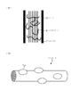
- cellulose and hemicellulose have a structure protected by lignin, as shown in FIG.
- an enzyme such as cellulase is added.
- a saccharified solution such as glucose as a fermentation raw material
- fermenting bacteria the final product alcohol
- This alcohol is then concentrated (distilled) to a predetermined concentration as required, for example.
- a saccharification reaction tank 101 for obtaining a saccharified solution and a fermentation reaction tank 102 for carrying out fermentation are used. And the biomass after the pretreatment are put into the saccharification reaction tank 101 for reaction, and then the saccharified solution and the fermenting bacteria obtained in the saccharification reaction tank 101 are supplied to the fermentation reaction tank 102 for fermentation and ethanol.
- the apparatus etc. which manufacture are used.
- the enzyme hydrolyzes cellulose and hemicellulose in the saccharification reaction tank 101 to produce a saccharified solution composed of monosaccharides such as glucose and xylose.
- an enzyme used for obtaining a saccharified solution is very expensive. Therefore, it is necessary to recover and reuse this enzyme without discarding it every reaction.
- the enzyme is recovered, for example, by performing membrane separation. In this case, the membrane becomes dirty and the life is shortened. The cost will be increased.
- the enzyme adsorbed on the biomass decomposition residue cannot be recovered. Therefore, it is necessary to examine a method that can reuse the enzyme at low cost including consumables such as membranes.
- the ratio of saccharified liquid obtained from input biomass (saccharification rate: weight of generated sugar / weight of cellulose and hemicellulose in biomass) ) Must be as high as possible.
- saccharified liquid obtained from input biomass saccharified liquid obtained from input biomass
- saccharification rate weight of generated sugar / weight of cellulose and hemicellulose in biomass
- Biomass contains a mixture of sites that are susceptible to enzymatic degradation, such as non-crystalline sites in cellulose, and sites that are difficult to decompose, such as sites with high crystallinity in cellulose.
- the decomposition proceeds first from the portion that is easily decomposed, and the amount of the portion that is easily decomposed decreases as the reaction proceeds, so the reaction rate is considered to be further slowed down.
- the amount of biomass charged into the reaction tank 101 and keeping the sugar concentration low can be reduced and the saccharification rate can be increased without spending so many days in the reaction.
- the concentration of the saccharified solution obtained is low, the fermentation ethanol concentration is also low. Therefore, the amount of energy required for distillation when producing concentrated ethanol, which is the final product, is increased, and the equipment capacity is increased.
- FIG. 26 (b) a method of performing an enzyme reaction and ethanol fermentation in the same reaction vessel 103 has been studied.
- biomass and enzyme are supplied into the reaction tank 103, and then fermented bacteria are supplied into the reaction tank 103, whereby the saccharified solution obtained by the reaction between the biomass and the enzyme is fermented with the fermenting bacteria at any time to produce ethanol.
- the saccharification rate can be increased because the concentration of the saccharified solution, which is an inhibitory factor of the saccharification reaction, is suppressed to reduce saccharide inhibition.
- the optimum reaction temperature for enzyme reaction is generally 50 ° C.
- the optimum reaction temperature for fermentation is 30 ° C. to 35 ° C. due to the heat resistance of the fermentation bacteria. Therefore, in this method, it is necessary to perform the reaction at 30 ° C. to 35 ° C. in order not to kill the fermenting bacteria, so that the reactivity of the enzyme is lowered. Therefore, the amount of enzyme to be added increases or, on the contrary, the reaction time becomes longer.
- a saccharified solution which is a precursor of ethanol, at as high a concentration as possible, for example, in order to suppress the energy required for ethanol concentration.
- a high-concentration saccharified solution can be obtained by increasing the amount of enzyme supplied and the amount of biomass charged in the reaction tank 101.
- this method increases the amount of enzyme used and further increases the amount of unreacted residue. Will increase the cost.
- Patent Document 2 in a simultaneous saccharification-fermentation reaction from fibrin to ethanol, a liquid part containing an enzyme and alcohol is brought into contact with a solid containing fibrin useful for the simultaneous saccharification-enzymization reaction. Although a technique for adsorbing an enzyme to the solid is described, production of a high-concentration saccharified solution has not been studied.
- JP 2006-87319 A Japanese Patent Laid-Open No. 55-144885 (claims, etc.)
- the present invention has been made under such circumstances, and an object thereof is to obtain a high-concentration saccharified solution at a low cost when an enzyme and biomass containing cellulose are reacted to obtain a saccharified solution.
- the object is to provide a method for producing a saccharified solution and a saccharification reaction apparatus.
- the method for producing a saccharified solution of the present invention comprises: In a method for obtaining a saccharified solution by reacting a cellulosic biomass, which is an aggregate of plants or an aggregate of plant processed products containing cellulose, and a saccharifying enzyme having cellulose saccharifying ability, A first reaction step of mixing a saccharifying enzyme and a cellulosic biomass in an aqueous solution, and saccharifying the biomass with a saccharifying enzyme; A first separation step of solid-liquid separation of the reaction solution obtained in the first reaction step to obtain a saccharified solution and a residue; A second reaction step of adding an added water to the residue obtained in the first separation step to prepare an aqueous solution, and saccharifying the residue with a saccharifying enzyme adsorbed to the residue in the aqueous solution; A third reaction step of adding cellulose-based biomass before saccharification reaction to the saccharified solution obtained in the first separation step, and saccharifying the biomass newly added by the saccharifying enzyme in the saccharified solution. It
- the first reaction step, the second reaction step, and the third reaction step are preferably performed using different reaction vessels.
- the proportion of lignin contained in the biomass is preferably 10% or less.
- the saccharification reaction apparatus of the present invention comprises: A saccharification reaction apparatus for carrying out the method for producing a saccharified solution described above, Two reaction vessels for mixing saccharifying enzyme and cellulosic biomass in an aqueous solution, and subjecting the biomass to a saccharification reaction with saccharifying enzyme; A biomass supply section for supplying biomass into these reaction vessels; A first enzyme supply unit for supplying a saccharifying enzyme into these reaction vessels; An additional water supply unit for supplying additional water into one of the two reaction tanks; A first separation unit for performing solid-liquid separation of a reaction solution generated by a reaction between biomass and a saccharifying enzyme in the one reaction tank to obtain a saccharified solution and a residue; A first transport unit for transporting the saccharified solution separated by the first separation unit to the other reaction tank of the two reaction tanks; The first reaction step is performed in the one reaction tank, the saccharified solution obtained by the first separation unit is then supplied to the other reaction tank, and then the reaction tank in which the residue is stored and the saccharified liquid Supply water and
- the first enzyme supply unit is for supplying a saccharification enzyme into the one reaction tank instead of supplying the saccharification enzyme into the two reaction tanks
- the additional water supply unit is for supplying the additional water into the other reaction tank instead of supplying the additional water into the one reaction tank
- the first transport unit is for transporting the residue instead of transporting the saccharified solution to the other reaction tank
- the control unit after performing the first reaction step, supplies the residue obtained by the first separation unit to the other instead of supplying the saccharified solution obtained by the first separation unit to the other reaction tank.
- a control signal may be output so as to be supplied to the reaction vessel.
- the first separation unit may be a means for separating the saccharified solution and the residue by sedimentation separation in the one reaction tank.
- the saccharification reaction apparatus of the present invention comprises: A saccharification reaction apparatus for carrying out the method for producing a saccharified solution described above, A first reaction tank, a second reaction tank, and a third reaction tank for mixing a saccharification enzyme and a cellulosic biomass in an aqueous solution, and subjecting the biomass to a saccharification reaction with a saccharification enzyme; A biomass supply unit for supplying biomass to each of the first reaction tank and the third reaction tank; An enzyme supply unit for supplying a saccharification enzyme into the first reaction tank; An additional water supply unit for supplying additional water into the second reaction tank; A first separation unit for solid-liquid separation of a reaction liquid obtained by the reaction of saccharifying enzyme and biomass in the first reaction tank to obtain a saccharified liquid and a residue; A first saccharified solution supply unit and a first residue supply unit for supplying the saccharified solution and the residue separated by the first separation unit to the third reaction tank and the second reaction tank, respectively; The first reaction step is performed in the first reaction tank,
- This step corresponds to the first reaction step, and the biomass used in the first reaction step is preferably a residue separated by the second separation unit.
- the first separation unit, the second separation unit, and the third separation unit are means for separating the saccharified solution and the residue by sedimentation separation in the first reaction tank, the second reaction tank, and the third reaction tank, respectively. It may be.
- the biomass is pretreated by an appropriate method, and the lignin content in the biomass is 10% or less, or the biomass is used paper, pulp, cotton, cotton fiber, etc. It is preferably a processed product of a plant material having a high cellulose content and a low lignin content.
- a high-concentration saccharified solution is obtained by reacting an enzyme with biomass containing cellulose
- the residue containing the saccharified solution (I) and unreacted biomass adsorbed by the enzyme by reacting biomass with the enzyme are separated, and a pH adjusting solution is supplied to the residue (I) to supply the residue (I) and the residue (I).
- the saccharified solution (II) is generated by reacting with the adsorbed enzyme.
- new biomass is supplied to the saccharified liquid (I), and the biomass and an enzyme remaining in the saccharified liquid (I) are reacted to generate a saccharified liquid (III) and a residue (III).
- the residue (III) and the saccharified solution (II) are reacted with the enzyme contained in the residue (III) and the saccharified solution (II) to further produce a monosaccharide. Therefore, the enzyme can be used effectively, and the amount of residue to be discarded can be suppressed, so that a high-concentration saccharified solution can be obtained at low cost.
- This saccharified liquid production apparatus is an apparatus for producing a saccharified liquid (a liquid in which a monosaccharide is dissolved) by reacting an enzyme with biomass containing cellulose made of a glucose polymer as a fermentation raw material. Yes, for example, compared with the apparatus shown in FIG.
- the sugar concentration contained in the saccharified liquid taken out to the outside is high, and the amount of residue consisting of unreacted biomass discharged to the outside is small, That is, the saccharification rate is high, and further, the amount of the enzyme discharged to the outside together with the saccharified solution and the residue is suppressed to be small.
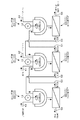
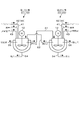
- This apparatus is provided with three reaction vessels 10 and each of these reaction vessels 10.
- a device for separating the saccharified solution produced in each reaction tank 10 and the residue comprising unreacted biomass such as a sedimentation separator, a pressure filtration device, a suction filtration device, a centrifugal separation device, a cyclone separation device or And a separation device 11 which is a separation unit composed of a filter press device and the like.
- Each reaction vessel 10 is provided with a heater for keeping the internal reaction solution at a reaction temperature of, for example, about 50 ° C. to 60 ° C., a thermocouple for measuring the temperature of the reaction solution, etc. (none of which are shown). ing.
- a heater for keeping the internal reaction solution at a reaction temperature of, for example, about 50 ° C. to 60 ° C.
- a thermocouple for measuring the temperature of the reaction solution, etc. (none of which are shown).
- the screw type stirrer was described in the figure, the type of the stirring device is not limited.
- the central reaction tank 10 in FIG. 1 is referred to as a first reaction tank 21, the left reaction tank 10 is referred to as a second reaction tank 22, and the right reaction tank 10 is referred to as a third reaction tank 23.
- the separation devices 11 connected to the first reaction tank 21, the second reaction tank 22, and the third reaction tank 23 are also referred to as a first separation device 31, a second separation device 32, and a third separation device 33, respectively. I will do it.
- reference numeral 12 denotes a stirrer for stirring the reaction solution containing the enzyme and biomass in the reaction tank 10 by, for example, a stirring blade, a stirring pump, air stirring, or the like, and a solid charged into each reaction tank 10.
- the stirring force and the stirring speed are individually adjusted.
- reference numerals 41, 42, 43 and 44 denote an enzyme supply path, a biomass supply path, a pH adjusting liquid supply path and a biomass addition path, respectively
- the first reaction tank 21 is a liquid containing an enzyme such as cellulase ( Aqueous solution), for example, water adjusted to about pH 5 (pH adjusting solution) and biomass containing cellulose
- the second reaction tank 22 can be supplied with added water, for example, water adjusted to about pH 5.
- the third reaction tank 23 is configured to be supplied with biomass in the same manner as the first reaction tank 21.
- Said enzyme supply path 41, biomass supply path 42 (biomass addition path 44), and pH adjustment liquid supply path 43 comprise an enzyme supply part, a biomass supply part, and an additional water supply part, respectively.
- These supply paths 41 to 43 are provided with valves (not shown) for supplying and disconnecting enzymes, biomass and pH adjusting liquid.
- the added water is for preparing a low sugar concentration solution as will be described later, and may be, for example, a buffer solution or pure water in addition to the pH adjusting solution.
- a screw feeder is used to supply (convey) solids such as biomass, and a belt conveyor or the like may be used in combination with the screw feeder. The same applies to the residues described later.
- the first separation device 31 includes a first saccharified solution supply path 51 and a first residue for supplying the saccharified solution and the residue separated by the separation device 31 to the third reaction tank 23 and the second reaction tank 22, respectively.
- the supply paths 52 are connected as a first saccharified solution supply unit and a first residue supply unit, respectively.
- the second separation device 32 includes a second saccharified solution supply path 53 that is a second saccharified solution supply unit for supplying the saccharified solution separated by the separation device 32 to the first reaction tank 21, and the second saccharified solution supply path 53.
- a residue discharge path 54 for discarding the residue separated by the separation device 32 is connected.
- the residue discharged from the residue discharge path 54 is lignin 3 contained in the biomass, and heat energy is recovered by burning, for example.
- the third separation device 33 includes a third residue supply path 55 for supplying the residue separated by the separation device 33 to the first reaction tank 21, and a saccharified solution recovery path 56 for taking out the saccharified solution separated by the separation device 33 to the outside.
- a third residue supply unit and a saccharified solution recovery unit are connected as a third residue supply unit and a saccharified solution recovery unit, and the saccharified solution recovered from the saccharified solution recovery path 56 is used as a raw material for chemical products or fermented by fermenting bacteria in a fermenter (not shown).
- an alcohol such as an ethanol solution is obtained.
- this ethanol solution is refine
- Each of the separation devices 31 to 33 is provided with a valve (not shown) so that residues and saccharified liquid discharged from the separation devices 31 to 33 can be supplied and disconnected.
- the biomass supplied to each of the first reaction tank 21 and the third reaction tank 23 is obtained by subjecting woody or herbaceous biomass to an appropriate pretreatment to destroy or dissolve and remove lignin.
- the pretreatment method include dilute sulfuric acid decomposition treatment, steam explosion treatment, ammonia explosion treatment, supercritical ammonia treatment, hot water / supercritical water treatment, microbial decomposition treatment, pulverization treatment, or chemical treatment.
- the lignin content in the biomass is, for example, 10% or less, preferably 5% or less.
- processed plant products such as waste paper, pulp, cotton, and cotton fibers are also treated biomass.
- the enzyme supplied to the first reaction tank 21 is a cellulose-degrading enzyme or a hemicellulose-degrading enzyme, and is, for example, a particle (solid) having a size of about several tens of millimeters. Further, as shown in FIG. 2 (b), this enzyme is adsorbed on the surface of cellulose 1 or hemicellulose 2, decomposes these cellulose 1 or hemicellulose 2 into monosaccharides, and adsorbs on cellulose 1 or hemicellulose 2. Before or after being decomposed, it has the property of being dispersed in the reaction solution and flowing like a liquid together with the reaction solution. This enzyme 7 is a very expensive substance.
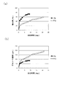
- FIG. 14 shows the results of an experiment conducted to confirm how the sugar concentration in the reaction solution increases when the biomass and the enzyme are reacted in the reaction solution (pH adjusting solution). It can be seen that the rate of increase in sugar concentration (biomass degradation rate) decreases with time. The reason why the degradation rate decreases in this way is that the enzymatic reaction is inhibited by the presence of sugar, and the biomass is degraded from the site where it is easily degraded, so the sugar concentration in the reaction solution over time (progress of reaction) It is thought that this is because the proportion of biomass that is difficult to decompose increases.
- saccharification rate the weight of the produced sugar / the weight of cellulose 1 and hemicellulose 2 in the biomass is called saccharification rate
- FIG. 16 shows the results of measuring how the enzyme concentration in the buffer changes with time when biomass is added to the buffer.
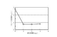
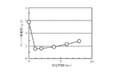
- FIG. 16 shows that when biomass is added to the buffer solution, the enzyme concentration in the buffer solution decreases, that is, the enzyme in the buffer solution is adsorbed to the biomass.
- the enzyme once adsorbed to the biomass returns to the buffer again as time passes, as shown in FIG. That is, it is considered that when the biomass is decomposed and saccharified (liquefied) so that the enzyme cannot be adsorbed to the biomass, the enzyme returns to the buffer solution.
- the enzyme reaction is inhibited by the saccharified solution filled around the residue, in addition to the fact that the residue is more difficult to decompose as described above,
- the decomposition reaction may be more difficult to proceed. Therefore, by placing the residue in a solution that is less affected by sugar inhibition, that is, separating the residue from the saccharified solution when the enzymatic reaction has progressed to some extent and the reaction has become difficult to proceed, It was verified whether or not the reaction proceeded by setting it to a small state (mixing the separated residue with a buffer solution containing no sugar).
- FIG. 18 and FIG. 19 show the results of separating the residue from the saccharified solution when 168 hours and 144 hours have elapsed from the start of the reaction, adding a buffer solution to the residue, and measuring the sugar concentration in the solution. It is. From this result, it was found that even if the reaction was difficult to proceed in the saccharified solution before separation, the reaction proceeded rapidly in a solution (low sugar concentration solution) having little influence of sugar inhibition. At this time, from the results of FIG. 16 and FIG. 17 described above, it was considered that the enzyme had already been adsorbed to the residue. Therefore, when the enzyme was not added to the buffer solution, the enzyme reaction still proceeded. It was found that even an enzyme whose reaction was difficult to proceed due to sugar inhibition could sufficiently contribute to the reaction in a low sugar concentration solution.
- FIGS. 14 to 19 are summarized as follows. After the enzyme and the biomass are reacted, the unreacted biomass (residue) is separated from the saccharified solution and reacted in a dilute solution having a sugar concentration. In other words, it has been found that the amount of biomass residue decreases through a two-step reaction process. However, since the sugar concentration of the saccharified solution obtained by enzymatic decomposition of this residue is low, this saccharified solution and new biomass or residue (residue containing more parts that are more easily decomposed than the above residue) are further reacted. Therefore, it is necessary to increase the saccharified liquid sugar concentration.
- the saccharified solution obtained by decomposing biomass is ethanolized by fermentation and then concentrated by, for example, distillation. Therefore, in order to produce ethanol as the final product at a low cost, it is necessary to suppress the energy required for the concentration. Therefore, it is desirable to increase the concentration of sugar contained in the saccharified solution as much as possible.
- it is necessary to increase the amount of enzyme to be added In order to increase the sugar concentration of the saccharified solution without spending a long reaction time, it is necessary to increase the amount of enzyme to be added.
- an enzyme recovery method using a separation membrane has been proposed, but this method increases the cost of the separation membrane facility.
- the enzyme added efficiently is recovered and reused by a simple method, and the operation further increases the concentration of the saccharified solution.
- FIG. 20 is a diagram of centrifuging the supernatant liquid (saccharified liquid) after 6 days from the start of the reaction in FIG. 14 from the residue, adding biomass to the supernatant liquid, and protein (enzyme) in the supernatant liquid. It is the result of measuring the concentration. From this result, it can be seen that a large amount of enzyme is present in the saccharified solution before the start of the experiment, but after adding biomass, the amount of enzyme in the saccharified solution decreases with the passage of time. That is, it can be said that the enzyme in the saccharified solution is adsorbed on the biomass. Therefore, as shown in FIGS.
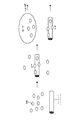
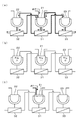
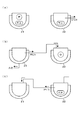
- an enzyme (enzyme solution) and pretreated biomass are charged into the first reaction tank 21 (step S1).
- the enzyme 7 is adsorbed to biomass (cellulose 1 and hemicellulose 2), and the decomposition reaction proceeds. Not all enzymes in solution are adsorbed to biomass, and some of them are in solution.
- Increasing the amount of enzyme added increases the amount of enzyme adsorbed to the biomass and increases the reaction rate, but at the same time increases the enzyme concentration in the solution.
- the reaction progresses and the sugar concentration increases, the influence of sugar inhibition and the proportion of the residue that is difficult to decompose in the residue increase, and the reaction rate gradually decreases.
- the saccharified solution and the residue generated in the first reaction tank 21 are separated by the first separation device 31, and the saccharified solution is subjected to the third reaction.
- a residue is supplied to the 2nd reaction tank 22 (step S2).
- the saccharified solution and the residue separated by the first separation device 31 each contain an enzyme as described above.
- pH adjustment liquid is supplied to the 2nd reaction tank 22 to which the residue was supplied from the 1st reaction tank 21 as a 2nd reaction process (step S31), and 3rd reaction.
- biomass is supplied to the third reaction tank 23 supplied with the saccharified solution from the first reaction tank 21 (step S32).
- step S32 biomass is supplied to the third reaction tank 23 supplied with the saccharified solution from the first reaction tank 21 (step S32).
- the second reaction tank 22 most of cellulose 1 and hemicellulose 2 in the residue supplied from the first reaction tank 21 are decomposed, and the enzyme 7 adsorbed on these cellulose 1 and hemicellulose 2 is absorbed. It diffuses into the reaction solution, and lignin 3 and the like contained in the residue remain as a residue. At this time, the sugar concentration of the saccharified liquid obtained in the second reaction tank 22 is lower than the sugar concentration of the saccharified liquid obtained in the first reaction tank 21.
- the enzyme contained in the saccharified solution generated in the first reaction tank 21 is adsorbed to the added biomass, and the enzyme concentration in the reaction solution is rapidly reduced.
- function strongly by the saccharified liquid supplied from the 1st reaction tank 21, as already mentioned, the site
- FIG. 6 (a) as a second separation step, the saccharified solution generated in the second reaction tank 22 and the residue are separated by the second separation device 32, and the saccharified solution is separated into the first saccharified solution.
- step S41 While supplying to the reaction tank 21, a residue is discarded out of the system (step S41). At this time, the enzyme adsorbed on the residue is discarded together with the residue. However, since the amount of the residue is extremely reduced by the reaction in the diluted sugar concentration solution as described above, most of the enzymes Is supplied to the first reaction tank 21 together with the saccharified solution, and the amount of discarded enzyme is extremely small.
- the obtained high-concentration saccharified solution and residue are separated by the third separation device 33, and the high-concentration saccharified solution is discharged out of the system.
- the residue is supplied to the first reaction tank 21 (step S42).
- the high-concentration saccharified solution is discharged out of the system together with the enzyme contained in the high-concentration saccharified solution, but most of the enzyme in the third reaction tank 23 (about 60% from the result of FIG. 20 described above). (About) is adsorbed to the unreacted biomass added to the third reaction tank 23, so that the amount of the enzyme discharged can be reduced.
- This high-concentration saccharified solution is sent, for example, to a fermenter (not shown), fermented to alcohol such as ethanol, and then concentrated by distillation or the like.
- step S5 this reaction process corresponds to the reaction process of step S1 described above.
- the saccharified solution and the residue obtained in the first reaction tank 21 are supplied to the third reaction tank 23 and the second reaction tank 22, respectively, and the above-described steps S2 to S5 are repeated. That is, as shown in FIG. 7, supplying biomass and a pH adjusting liquid to the saccharified liquid and the residue obtained in the first reaction tank 21 in the third reaction tank 23 and the second reaction tank 22, respectively.
- a high-concentration saccharified liquid can be obtained continuously. It will be. Therefore, in this apparatus, the biomass and the pH adjusting liquid are intermittently charged into the third reaction tank 23 and the second reaction tank 22.
- reaction solutions having different sugar concentrations are prepared in each reaction tank 10, that is, as shown in FIG. 8A, in the three reaction tanks 10, from the second reaction tank 22 on the left side to the right side.
- the sugar concentration will increase in order toward the third reaction tank 23. Therefore, the degree of sugar inhibition increases in order from the second reaction tank 22 on the left side toward the third reaction tank 23 on the right side, and therefore, added to the third reaction tank 23 on the right side as shown in FIG.
- the done biomass is sequentially decomposed from the highly reactive site (the site that is not easily affected by sugar inhibition) toward the second reaction tank 22 on the left side. Further, the pH adjustment liquid supplied to the second reaction tank 22 on the left side gradually increases in sugar concentration toward the third reaction tank 23 on the right side, and the third separation device 33 leaves the system as a high-concentration saccharified liquid. It will be taken out.
- the enzyme supplied to the first reaction tank 21 is adsorbed to the residue from the second reaction tank 22 and discharged out of the system, or is discharged out of the system together with the high-concentration saccharified solution from the third reaction tank 23.
- the amount of residue produced is reduced, and in the third reaction tank 23, the amount of enzyme adsorbed by the residue and returned to the first reaction tank 21 is increased.
- it circulates between the three reaction tanks 10. That is, in order to utilize the property that the enzyme is adsorbed on the biomass (residue) and the enzyme returns to the reaction solution by the decomposition of the biomass, the amount of residue in the three reaction vessels 10 as shown in FIG.
- the amount of the residue is increased in order from the second reaction tank 22 on the left side toward the third reaction tank 23 on the right side. Therefore, it can be said that the second reaction tank 22 has an enzyme recovery function from the residue, and the third reaction tank 23 has an enzyme recovery function from the reaction solution.
- the tank 21 is supplemented with the enzyme (step S6).
- the saccharification reaction apparatus is provided with a control unit (not shown). Then, a control signal is output to the saccharification reaction apparatus so as to stir and heat the reaction liquid in each of the reaction tanks 21 to 23.
- a saccharified solution when a saccharified solution is obtained by reacting an enzyme and biomass containing cellulose, the saccharified solution in which the enzyme and the enzyme are dispersed in the first reaction tank 21 and the enzyme are adsorbed.
- the residue containing the unreacted biomass is generated, and then the saccharified solution and the residue are separated, and the pH adjustment solution is supplied to the residue in the second reaction tank 22 to increase the sugar concentration than the saccharified solution.
- a saccharified solution is prepared by reacting the residue and the enzyme adsorbed on the residue in the diluted solution. Therefore, the enzyme can be effectively used and recovered, and the amount of the discarded residue can be suppressed (a high saccharification rate can be obtained), so that a saccharified solution can be obtained at low cost.
- the enzyme can be collected and reused, for example, the amount of enzyme input can be increased, and in this case, the saccharified solution can be obtained in a short time.
- the enzyme dispersed in the saccharified solution is reacted with the easily reactive site in the newly added biomass. Therefore, the enzyme can be effectively used and the sugar concentration in the saccharified solution can be quickly increased. Furthermore, the enzyme dispersed in the saccharified solution can be recovered by adsorbing to the newly added biomass residue. If it becomes possible to produce a saccharified solution with a high sugar concentration and reduce the amount of enzyme to be discharged, the size of each reaction tank 10 can be reduced, the cost of equipment can be reduced, and the energy required for subsequent distillation can be reduced. Furthermore, since the enzyme cost can be reduced, a saccharified solution and ethanol can be obtained at a low cost.
- generated in the 2nd reaction tank 22 and the 3rd reaction tank 23 are returned again to the 1st reaction tank 21, they utilize these saccharified liquid and residue effectively, and are continuously. While obtaining a high concentration saccharified solution, it is possible to reduce the amount of residues and enzymes discarded. Moreover, since said process is performed using the three reaction tanks 10, a process can be performed efficiently. In addition, when the enzymes are circulated (reused) in the three reaction tanks 10, for example, no consumables such as membranes are used, so that a high-concentration saccharified solution can be obtained at low cost. Further, in the second reaction tank 22, the enzyme is discharged out of the system together with the residue. Since this residue is mainly lignin, the content of lignin in the biomass to be charged is as described above. By reducing in advance, the amount of enzyme discharged together with the residue can be suppressed.
- the enzyme is supplied to the first reaction tank 21, but may be supplied to the second reaction tank 22.
- the three reaction vessels 10 are provided.
- the sugar concentration of the pH adjusting liquid supplied to the second reaction tank 22 gradually increases toward the third reaction tank 23 on the right side. Therefore, since the biomass supplied to the third reaction tank 23 having a very high sugar concentration is strongly subjected to sugar inhibition, a highly reactive site reacts in the biomass, and most of the enzymes in the third reaction tank 23 react. Is recovered from the third reaction tank 23 together with the residue.
- each reaction vessel 10 the same separation device 11 can be shared with each reaction vessel.
- the sedimentation and filtration of the residue may be performed in each reaction tank 10, for example, the supernatant liquid may be sucked, and the deposits and filtrate (residue) may be taken out or left in the reaction tank.
- each reaction vessel 10 also serves as a separation means.
- the number of reaction tanks 10 may be two.
- An example will be described with reference to FIG.
- symbol is attached
- each of the reaction tanks 21 and 22 includes an enzyme supply path 41 and a biomass supply path 42 (biomass, respectively).
- An additional path 44), a pH adjusting liquid supply path 43, a residue discharge path 54, and a saccharified liquid recovery path 56 are connected.
- the supply path and the recovery path enzyme supply path 41, biomass supply path 42 (biomass addition path 44), pH adjusting liquid supply path 43, residue discharge path 54, and saccharified liquid recovery path 56
- a first supply path for sucking the saccharified liquid, which is a supernatant in the reaction tanks 21 and 22, and supplying the reaction tanks 21 and 22 to the other reaction tanks 22 and 21.
- Part) 61 and the second supply path 62 are connected to each other.
- step S1 first, when an enzyme, a pH adjusting solution, and biomass are supplied to the first reaction tank 21, a saccharified solution and a residue are generated (step S1).
- the saccharified solution and the residue are separated by, for example, sedimentation separation, and the saccharified solution is supplied to the second reaction tank 22 as shown in FIG.
- step S31 while supplying pH adjustment liquid to the 1st reaction tank 21 with which the residue was left (step S31), biomass is supplied to the 2nd reaction tank 22 (step S32).
- step S42 the saccharified solution and the residue generated in each of the reaction tanks 21 and 22 are settled and separated, and the high-concentration saccharified solution generated in the second reaction tank 22 is removed from the system as shown in FIG. 13 (a).
- step S42 the saccharified liquid produced
- the residue remaining in the tank 21 is discarded outside the system (step S41).
- the residue reacts with the saccharified solution (step S5), and thus the steps S2 (FIG. 13C) to S5 are performed on the saccharified solution and the residue, respectively. .
- the high-concentration saccharified solution and the dilute solution are prepared alternately in the first reaction tank 21 and the second reaction tank 22. Further, when the enzyme is insufficient, the enzyme is replenished to any one of the reaction tanks 21 and 22. Also in this embodiment, the same operation and effect as the above-described embodiment can be obtained.
- the biomass used as the raw material for the saccharified liquid in each of the above examples is a processed product of plant raw materials such as waste paper, pulp, cotton fibers, etc., in addition to woody or herbaceous raw materials, and contains cellulose 1. Moreover, you may be comprised from the multiple types of raw material containing these celluloses 1.
- the enzyme a cellulose-degrading enzyme or a combination of cellulose-degrading enzyme and hemicellulose-degrading enzyme is preferable.
- biomass and enzyme are reacted outside the system in advance to produce a saccharified solution and a residue.
- the above-mentioned treatment is performed by supplying the same to separate reaction vessels 10.
- FIG. 18 Experiment for confirming change in sugar concentration by putting residue in buffer (dilute sugar concentration solution) (Experimental conditions)
- Substrate (biomass) Centrifugated residue produced under the following residue production conditions 16 g (wet condition) Reaction solution: the above residue + buffer solution 50 ml (Residue generation conditions)
- Substrate (biomass) Filter paper 10g Enzyme: 5ml Buffer solution: 95ml Saccharification time: 168h (Experimental result) Even if the decomposition reaction is difficult to proceed, if the residue is separated from the saccharified solution having a high sugar concentration and put into a dilute sugar concentration solution, the decomposition reaction proceeds rapidly.
- FIG. 19 Experiment for confirming change in sugar concentration by putting residue in buffer (dilute sugar concentration solution) (Experimental conditions)
- Substrate (biomass) 10 g of residue obtained by centrifuging the reaction solution 6 days after the start of the reaction in the experiment of FIG.
- Reaction solution the above residue + buffer solution 100 ml (Experimental result)
- the residue is difficult to proceed with the decomposition reaction, the decomposition reaction proceeded quickly in the diluted sugar concentration solution.
Landscapes
- Organic Chemistry (AREA)
- Chemical & Material Sciences (AREA)
- Engineering & Computer Science (AREA)
- Zoology (AREA)
- Life Sciences & Earth Sciences (AREA)
- Wood Science & Technology (AREA)
- Chemical Kinetics & Catalysis (AREA)
- Microbiology (AREA)
- General Chemical & Material Sciences (AREA)
- Biotechnology (AREA)
- Health & Medical Sciences (AREA)
- Biochemistry (AREA)
- Bioinformatics & Cheminformatics (AREA)
- General Engineering & Computer Science (AREA)
- General Health & Medical Sciences (AREA)
- Genetics & Genomics (AREA)
- Preparation Of Compounds By Using Micro-Organisms (AREA)
- Apparatus Associated With Microorganisms And Enzymes (AREA)
Abstract
Description
植物の集合体またはセルロースを含む植物の加工物の集合体であるセルロース系バイオマスと、セルロース糖化能力を有する糖化酵素とを反応させて糖化液を得る方法において、
糖化酵素とセルロース系バイオマスとを水溶液中で混合し、バイオマスを糖化酵素により糖化反応させる第1の反応工程と、
前記第1の反応工程で得られた反応液を固液分離して糖化液と残渣とを得る第1の分離工程と、
前記第1の分離工程で得られた残渣に添加水を加えて水溶液を調製し、この水溶液中にて当該残渣に吸着している糖化酵素によりこの残渣を糖化反応させる第2の反応工程と、
前記第1の分離工程で得られた糖化液に糖化反応前のセルロース系バイオマスを加えて、当該糖化液中の糖化酵素により新たに加えたバイオマスを糖化反応させる第3の反応工程と、を含むことを特徴とする。
前記第2の反応工程で得られた反応液を固液分離して糖化液と残渣とを得る第2の分離工程と、
前記第3の反応工程で得られた反応液を固液分離して高濃度糖化液と残渣とを得る第3の分離工程と、
前記第2の分離工程で得られた糖化液と、前記第3の分離工程で得られた残渣と、を混合して糖化反応させる反応工程と、を含み、
この反応工程は前記第1の反応工程に相当し、前記第1の反応工程に用いたバイオマスは、前記第3の分離工程で得られた残渣であることが好ましい。
前記第2の反応工程の水溶液及び前記第2の分離工程で分離された糖化液の少なくとも1つに対して糖化酵素を補充する工程を行うことが好ましい。
前記バイオマスに含まれているリグニンの割合は、10%以下であることが好ましい。
上記記載の糖化液の製造方法を実施するための糖化反応装置であって、
糖化酵素とセルロース系バイオマスとを水溶液中で混合し、バイオマスを糖化酵素により糖化反応させるための2つの反応槽と、
これら反応槽内にバイオマスを供給するためのバイオマス供給部と、
これら反応槽内に糖化酵素を供給するための第1酵素供給部と、
前記2つの反応槽のうちの一方の反応槽内に添加水を供給するための添加水供給部と、
前記一方の反応槽においてバイオマスと糖化酵素との反応により生成する反応液の固液分離を行って糖化液と残渣とを得るための第1分離部と、
前記第1分離部により分離した糖化液を前記2つの反応槽のうちの他方の反応槽に搬送するための第1搬送部と、
前記一方の反応槽において前記第1の反応工程を行い、次いで前記第1分離部により得られた糖化液を前記他方の反応槽に供給し、しかる後残渣が貯留された反応槽及び糖化液の貯留された反応槽に夫々添加水及び糖化反応前のセルロース系バイオマスを供給して、前記2つの反応槽において夫々前記第2の反応工程及び前記第3の反応工程を行うように制御信号を出力する制御部と、を備えたことを特徴とする。
前記添加水供給部は、添加水を前記一方の反応槽内に供給する代わりに前記他方の反応槽内に供給するためのものであり、
前記第1搬送部は、前記他方の反応槽に糖化液を搬送する代わりに残渣を搬送するためのものであり、
前記制御部は、前記第1の反応工程を行った後、前記第1分離部により得られた糖化液を他方の反応槽に供給する代わりに前記第1分離部により得られた残渣を前記他方の反応槽に供給するように制御信号を出力しても良い。
前記第1分離部は、前記一方の反応槽内において沈降分離により糖化液と残渣とを分離する手段であっても良い。
上記に記載の糖化液の製造方法を実施するための糖化反応装置であって、
糖化酵素とセルロース系バイオマスとを水溶液中で混合し、バイオマスを糖化酵素により糖化反応させるための第1反応槽、第2反応槽及び第3反応槽と、
前記第1反応槽及び前記第3反応槽の各々にバイオマスを供給するためのバイオマス供給部と、
前記第1反応槽内に糖化酵素を供給するための酵素供給部と、
前記第2反応槽内に添加水を供給するための添加水供給部と、
前記第1反応槽において糖化酵素とバイオマスとの反応により得られた反応液を固液分離して糖化液と残渣とを得る第1分離部と、
前記第1分離部により分離された糖化液及び残渣を夫々前記第3反応槽及び前記第2反応槽に供給するための第1糖化液供給部及び第1残渣供給部と、
前記第1反応槽において前記第1の反応工程を行い、次いで前記第1反応槽で得られた反応液から前記第1分離部により残渣と糖化液とを分離して前記第2反応槽及び前記第3反応槽にこれらの残渣と糖化液とを夫々供給し、しかる後前記第2反応槽及び前記第3反応槽に夫々添加水及び糖化反応前のセルロース系バイオマスを供給して、夫々の反応槽において前記第2の反応工程及び前記第3の反応工程を行うように制御信号を出力する制御部と、を備えたことを特徴とする。
前記第3反応槽において生成した反応液を固液分離して高濃度糖化液と残渣とを得る第3分離部と、
前記第2分離部において分離した糖化液を前記第1反応槽に供給する第2糖化液供給部と、
前記第3分離部において分離された残渣を前記第1反応槽に供給する第3残渣供給部と、
前記第3分離部において分離された高濃度糖化液を外部に取り出すための糖化液回収部と、を備え、
前記第2反応槽で得られた反応液から前記第2分離部を用いて糖化液と残渣とを得ると共に、前記第3反応槽で得られた反応液から前記第3分離部を用いて高濃度糖化液と残渣とを得て、前記第2分離部で分離した糖化液と前記第3分離部で分離した残渣とを前記第1反応槽において反応させる工程を行い、
この工程は前記第1の反応工程に相当し、前記第1の反応工程に用いたバイオマスは、前記第2分離部で分離した残渣であることが好ましい。
前記バイオマスは、適当な方法により前処理操作が施され、前記バイオマスにに含まれているリグニンの割合は、10%以下であること、あるいは前記バイオマスは、古紙、パルプ、綿、綿繊維などのセルロース含有率が高くかつリグニン含有率が低い、植物原料の加工製品であることが好ましい。
本発明の糖化液製造方法を行うための糖化液製造装置の第1の実施の形態について、図1を参照して説明する。この糖化液製造装置(糖化反応装置)は、酵素と発酵原料であるグルコースの重合物からなるセルロースを含むバイオマスとを反応させて糖化液(単糖が溶解した液)を製造するための装置であり、例えば既述の図26に示した装置と比較して、外部に取り出される糖化液中に含まれる糖濃度が高く、且つ外部に排出される未反応のバイオマスからなる残渣の量が少なく、即ち糖化率が高く、更には糖化液や残渣と共に外部に排出される酵素の量が少なく抑えられるように構成されている。この装置が上記のように構成されている理由については後で詳述するが、先ず装置の構成について簡単に説明すると、この装置は、3つの反応槽10と、これらの反応槽10毎に設けられ、各反応槽10にて生成した糖化液と未反応のバイオマスからなる残渣とを分離するための装置、例えば沈降分離装置、加圧濾過装置、吸引濾過装置、遠心分離装置、サイクロン分離装置またはフィルタープレス装置などからなる分離部である分離装置11と、を備えている。
第1反応槽21及び第3反応槽23に各々供給されるバイオマスは、木質系あるいは草本系バイオマスに適当な前処理を施し、リグニンを破壊あるいは溶解除去したものである。この前処理方法としては、例えば希硫酸分解処理、水蒸気爆砕処理、アンモニア爆砕処理、超臨界アンモニア処理、熱水・超臨界水処理、微生物分解処理、微粉砕処理または化学薬品処理などがあてはまる。バイオマス中におけるリグニンの含有量は、例えば10%以下好ましくは5%以下となっている。また、前処理を施したバイオマス以外に、古紙、パルプ、綿、綿繊維などの植物加工品も処理対象バイオマスとなる。
次に、上記の装置において、既述の図26に示した装置と比較して、外部に取り出される糖化液中に含まれる糖濃度が高く、且つ外部に排出される残渣の量が少なく、更には糖化液や残渣と共に外部に排出される酵素の量が少なく抑えられている理由について、以下の実施例における図14~図24に示す実験結果及び考察に基づいて詳述する。尚、これらの図14~図24について、詳細な実験条件や結果については後述の実施例にて説明する。
以上の実験結果により得られた知見に基づいてバイオマスの分解を行う本発明の糖化液製造方法において、既述のように、図26に示す装置と比べて、外部に取り出される糖化液中の糖濃度が高く、且つ外部に廃棄される残渣の量が少なく、更には糖化液や残渣と共に外部に排出される酵素の量が少なく抑えられながらバイオマスが分解されていく様子について、図3に示す反応全体のフローに基づいて以下に説明する。
ここで、上記の各ステップを自動で行う場合には、この糖化反応装置には図示しない制御部が設けられ、この制御部は上記の各ステップを行うように既述の図示しないバルブの給断、各反応槽21~23内の反応液の撹拌及び加熱などを行うように糖化反応装置に制御信号を出力することとなる。
また、第2反応槽22において、残渣と共に酵素が系外に排出されることになるが、この残渣が主にリグニンであることから、投入するバイオマス中のリグニンの含有量を既述のように予め少なくしておくことによって、残渣と共に排出される酵素の量を抑えることができる。
また、上記の例では3つの反応槽10を設けたが、例えば図10に示すように、3つ以上例えば5つ設けても良い。その場合には、第2反応槽22に供給されたpH調整液は、右側の第3反応槽23に向かうにつれて次第に糖濃度が高くなっていく。そのため、糖濃度の極めて高い第3反応槽23に供給されたバイオマスは、糖阻害を強く受けるため、バイオマス中において反応性の極めて高い部位が反応し、当該第3反応槽23の酵素の大部分が第3反応槽23から残渣と共に回収されることになる。また、右側の第3反応槽23から左側の第2反応槽22に向かうにつれて糖濃度が低くなっていくので、第2反応槽22には反応性の極めて低いバイオマスが残渣として供給され、当該第2反応槽22にて分解されることになる。そのため、第2反応槽22から系外に排出される残渣の量が微量になり、そのため残渣と共に排出される酵素の量も少なくなる。従って、反応槽10の数量を増やすほど、上記の例よりも更に高濃度の糖化液が得られ、また廃棄される残渣の量及び酵素の量が一層少なくなることになる。
また、反応槽10の数量としては2つであっても良い。このような糖化液製造装置について、上記のように残渣を沈降させることにより2つの第1反応槽21及び第2反応槽22が夫々第1分離装置31及び第2分離装置32を兼用する場合を例に挙げて図11を参照して説明する。尚、既述の実施の形態と同じ部位については同じ符号を付して説明を省略する。
この実施の形態においても、前記の実施の形態と同様の作用及び効果が得られる。
また、上記の各例にて糖化液の原料として用いられるバイオマスとしては、木質系や草本系原料の他、古紙、パルプ、綿繊維などの植物原料の加工製品で、セルロース1を含んでいれば良いし、またこれらのセルロース1を含む原料の複数種類から構成されていても良い。酵素としては、セルロース分解酵素あるいはセルロース分解酵素とヘミセルロース分解酵素の組み合わせなどが良い。また、上記のように糖化液を製造するにあたって、予め初期段階においては系外でバイオマスと酵素とを反応させて糖化液と残渣とを生成させ、連続運転時においてはこれらの糖化液と残渣とを夫々別の反応槽10に供給して上記の処理を行う方法も本発明に含まれる。
・図14:反応時間と糖濃度との相関関係評価実験
(実験条件)
基質(バイオマス):ろ紙 10g
酵素:5ml
緩衝液:95ml
(実験結果)
時間の経過と共に分解速度(糖濃度の増加速度)が減少していた。
(実験条件)
基質(バイオマス):ろ紙
基質充填量:10g、25g、30g、35g、40g
酵素:5ml
緩衝液:95ml
反応温度:50℃
(実験結果)
原料の充填量を多くすると、糖化率は減少していた。
(実験条件)
基質(バイオマス):ろ紙 10g
酵素:5ml
緩衝液:95ml
(実験結果)
酵素液にバイオマスを投入すると、溶液中の酵素(タンパク質)濃度が減少していた。
(実験条件)
基質(バイオマス):ろ紙 10g
酵素:5ml
pH調整液:95ml
(実験結果)
酵素液にバイオマスを投入すると、バイオマスに酵素が吸着して溶液中の酵素量が減少したが、その後しばらく経過すると、バイオマスに吸着した酵素がバイオマスの分解により再度溶液中に戻ってきていた。
(実験条件)
基質(バイオマス):以下の残渣生成条件で生成した残渣を遠心分離したもの 16g(ウェット状態)
反応液:上記の残渣+緩衝液 50ml
(残渣生成条件)
基質(バイオマス):ろ紙 10g
酵素:5ml
緩衝液:95ml
糖化時間:168h
(実験結果)
分解反応が進みにくくなっていた残渣であっても、糖濃度の高くなった糖化液から分離して希薄糖濃度溶液中に投入すると、速やかに分解反応が進行していた。
(実験条件)
基質(バイオマス):図14の実験において反応開始から6日経過した反応溶液を遠心分離して得られた残渣 10g
反応液:上記の残渣+緩衝液 100ml
(実験結果)
同様に分解反応が進みにくくなっていた残渣であっても、希薄糖濃度溶液中において速やかに分解反応が進行していた。
(実験条件)
基質(バイオマス):ろ紙 10g
反応液:図14と同条件の実験において実験開始から6日経過した反応溶液を遠心分離して得られた糖化液 100ml
(実験結果)
糖阻害が起こって分解反応が進みにくくなる程度の糖化液にバイオマスを投入すると、糖化液中の酵素(タンパク質)濃度が減少していた。
(実験条件)
基質(バイオマス):ろ紙 10g
反応液:図14と同条件の実験において実験開始から1日経過した反応溶液を遠心分離して得られた糖化液 100ml
(実験結果)
糖阻害が起こって分解反応が進みにくくなる程度に糖濃度が高くなった糖化液であっても、新たにバイオマスを投入すると、バイオマスが速やかに分解されて糖濃度が上昇していた。
(実験条件)
基質(バイオマス):ろ紙 10g
反応液:図14と同条件の実験において実験開始から6日経過した反応溶液を遠心分離して得られた糖化液 100ml
(実験結果)
上記の実験と同様に、糖濃度が高くなった糖化液であっても、新たにバイオマスを投入することによってバイオマスが速やかに分解されて糖濃度が上昇していた。
(実験条件)
基質(バイオマス):ろ紙
基質濃度:10重量/体積%
酵素:5体積%
pH調整液:50mM酢酸緩衝液 pH5
反応温度:50℃
(実験結果)
実験開始から50h経過した時に、新たに10重量/体積%のろ紙を追加すると、追加前には上昇速度が遅くなっていた糖濃度が速やかに上昇した。
(実験条件)
基質(バイオマス):ろ紙
基質濃度:10重量/体積%
酵素:5体積%
pH調整液:50mM酢酸緩衝液 pH5
反応温度:50℃
(実験結果)
実験開始から50h経過した時に、新たに10重量/体積%のろ紙を追加すると、追加前よりも追加後のバイオマスの糖化率が低くなっていた。
2 ヘミセルロース
7 酵素
21 第1反応槽
22 第2反応槽
23 第3反応槽
31~33 分離装置
41 酵素供給路
42 バイオマス供給路
43 pH調整液供給路
44 バイオマス追加路
Claims (12)
- 植物の集合体またはセルロースを含む植物の加工物の集合体であるセルロース系バイオマスと、セルロース糖化能力を有する糖化酵素とを反応させて糖化液を得る方法において、
糖化酵素とセルロース系バイオマスとを水溶液中で混合し、バイオマスを糖化酵素により糖化反応させる第1の反応工程と、
前記第1の反応工程で得られた反応液を固液分離して糖化液と残渣とを得る第1の分離工程と、
前記第1の分離工程で得られた残渣に添加水を加えて水溶液を調製し、この水溶液中にて当該残渣に吸着している糖化酵素によりこの残渣を糖化反応させる第2の反応工程と、
前記第1の分離工程で得られた糖化液に糖化反応前のセルロース系バイオマスを加えて、当該糖化液中の糖化酵素により新たに加えたバイオマスを糖化反応させる第3の反応工程と、を含むことを特徴とする糖化液の製造方法。 - 前記第1の反応工程と前記第2の反応工程と前記第3の反応工程とは、夫々互いに異なる反応槽を用いて行われることを特徴とする請求項1に記載の糖化液の製造方法。
- 前記第2の反応工程で得られた反応液を固液分離して糖化液と残渣とを得る第2の分離工程と、
前記第3の反応工程で得られた反応液を固液分離して高濃度糖化液と残渣とを得る第3の分離工程と、
前記第2の分離工程で得られた糖化液と、前記第3の分離工程で得られた残渣と、を混合して糖化反応させる反応工程と、を含み、
この反応工程は前記第1の反応工程に相当し、前記第1の反応工程に用いたバイオマスは、前記第3の分離工程で得られた残渣であることを特徴とする請求項1に記載の糖化液の製造方法。 - 前記第2の反応工程の水溶液及び前記第2の分離工程で分離された糖化液の少なくとも1つに対して糖化酵素を補充する工程を行うことを特徴とする請求項3に記載の糖化液の製造方法。
- 前記バイオマスに含まれているリグニンの割合は、10%以下であることを特徴とする請求項1に記載の糖化液の製造方法。
- 請求項1に記載の糖化液の製造方法を実施するための糖化反応装置であって、
糖化酵素とセルロース系バイオマスとを水溶液中で混合し、バイオマスを糖化酵素により糖化反応させるための2つの反応槽と、
これら反応槽内にバイオマスを供給するためのバイオマス供給部と、
これら反応槽内に糖化酵素を供給するための第1酵素供給部と、
前記2つの反応槽のうちの一方の反応槽内に添加水を供給するための添加水供給部と、
前記一方の反応槽においてバイオマスと糖化酵素との反応により生成する反応液の固液分離を行って糖化液と残渣とを得るための第1分離部と、
前記第1分離部により分離した糖化液を前記2つの反応槽のうちの他方の反応槽に搬送するための第1搬送部と、
前記一方の反応槽において前記第1の反応工程を行い、次いで前記第1分離部により得られた糖化液を前記他方の反応槽に供給し、しかる後残渣が貯留された反応槽及び糖化液の貯留された反応槽に夫々添加水及び糖化反応前のセルロース系バイオマスを供給して、前記2つの反応槽において夫々前記第2の反応工程及び前記第3の反応工程を行うように制御信号を出力する制御部と、を備えたことを特徴とする糖化反応装置。 - 前記第1酵素供給部は、糖化酵素を前記2つの反応槽内に供給する代わりに前記一方の反応槽内に供給するためのものであり、
前記添加水供給部は、添加水を前記一方の反応槽内に供給する代わりに前記他方の反応槽内に供給するためのものであり、
前記第1搬送部は、前記他方の反応槽に糖化液を搬送する代わりに残渣を搬送するためのものであり、
前記制御部は、前記第1の反応工程を行った後、前記第1分離部により得られた糖化液を他方の反応槽に供給する代わりに前記第1分離部により得られた残渣を前記他方の反応槽に供給するように制御信号を出力することを特徴とする請求項6に記載の糖化反応装置。 - 前記第1分離部は、前記一方の反応槽内において沈降分離により糖化液と残渣とを分離する手段であることを特徴とする請求項7に記載の糖化反応装置。
- 請求項1に記載の糖化液の製造方法を実施するための糖化反応装置であって、
糖化酵素とセルロース系バイオマスとを水溶液中で混合し、バイオマスを糖化酵素により糖化反応させるための第1反応槽、第2反応槽及び第3反応槽と、
前記第1反応槽及び前記第3反応槽の各々にバイオマスを供給するためのバイオマス供給部と、
前記第1反応槽内に糖化酵素を供給するための酵素供給部と、
前記第2反応槽内に添加水を供給するための添加水供給部と、
前記第1反応槽において糖化酵素とバイオマスとの反応により得られた反応液を固液分離して糖化液と残渣とを得る第1分離部と、
前記第1分離部により分離された糖化液及び残渣を夫々前記第3反応槽及び前記第2反応槽に供給するための第1糖化液供給部及び第1残渣供給部と、
前記第1反応槽において前記第1の反応工程を行い、次いで前記第1反応槽で得られた反応液から前記第1分離部により残渣と糖化液とを分離して前記第2反応槽及び前記第3反応槽にこれらの残渣と糖化液とを夫々供給し、しかる後前記第2反応槽及び前記第3反応槽に夫々添加水及び糖化反応前のセルロース系バイオマスを供給して、夫々の反応槽において前記第2の反応工程及び前記第3の反応工程を行うように制御信号を出力する制御部と、を備えたことを特徴とする糖化反応装置。 - 前記第2反応槽において生成した反応液を固液分離して糖化液と残渣とを得る第2分離部と、
前記第3反応槽において生成した反応液を固液分離して高濃度糖化液と残渣とを得る第3分離部と、
前記第2分離部において分離した糖化液を前記第1反応槽に供給する第2糖化液供給部と、
前記第3分離部において分離された残渣を前記第1反応槽に供給する第3残渣供給部と、
前記第3分離部において分離された高濃度糖化液を外部に取り出すための糖化液回収部と、を備え、
前記第2反応槽で得られた反応液から前記第2分離部を用いて糖化液と残渣とを得ると共に、前記第3反応槽で得られた反応液から前記第3分離部を用いて高濃度糖化液と残渣とを得て、前記第2分離部で分離した糖化液と前記第3分離部で分離した残渣とを前記第1反応槽において反応させる工程を行い、
この工程は前記第1の反応工程に相当し、前記第1の反応工程に用いたバイオマスは、前記第2分離部で分離した残渣であることを特徴とする請求項9に記載の糖化反応装置。 - 前記第1分離部、前記第2分離部及び前記第3分離部は、夫々前記第1反応槽、前記第2反応槽及び前記第3反応槽において沈降分離により糖化液と残渣とを分離する手段であることを特徴とする請求項10に記載の糖化反応装置。
- 前記バイオマスに含まれているリグニンの割合は、10%以下であることを特徴とする請求項6または9に記載の糖化反応装置。
Priority Applications (2)
| Application Number | Priority Date | Filing Date | Title |
|---|---|---|---|
| US13/261,131 US20120107920A1 (en) | 2009-07-17 | 2010-07-15 | Method of producing sugar solution and saccharification device |
| BR112012000840A BR112012000840A2 (pt) | 2009-07-17 | 2010-07-15 | método para produzir uma solução de açucar, e dispositivo de sacarificação. |
Applications Claiming Priority (2)
| Application Number | Priority Date | Filing Date | Title |
|---|---|---|---|
| JP2009-169527 | 2009-07-17 | ||
| JP2009169527A JP2011019483A (ja) | 2009-07-17 | 2009-07-17 | 糖化液製造方法及び糖化反応装置 |
Publications (1)
| Publication Number | Publication Date |
|---|---|
| WO2011007574A1 true WO2011007574A1 (ja) | 2011-01-20 |
Family
ID=43449184
Family Applications (1)
| Application Number | Title | Priority Date | Filing Date |
|---|---|---|---|
| PCT/JP2010/004608 Ceased WO2011007574A1 (ja) | 2009-07-17 | 2010-07-15 | 糖化液製造方法及び糖化反応装置 |
Country Status (4)
| Country | Link |
|---|---|
| US (1) | US20120107920A1 (ja) |
| JP (1) | JP2011019483A (ja) |
| BR (1) | BR112012000840A2 (ja) |
| WO (1) | WO2011007574A1 (ja) |
Cited By (7)
| Publication number | Priority date | Publication date | Assignee | Title |
|---|---|---|---|---|
| JP2012100617A (ja) * | 2010-11-12 | 2012-05-31 | Oji Paper Co Ltd | リグノセルロース系原料の酵素糖化処理方法 |
| US20140004573A1 (en) * | 2012-07-02 | 2014-01-02 | Xyleco, Inc. | Processing biomass |
| EP2682472A4 (en) * | 2011-03-03 | 2014-10-08 | Toray Industries | METHOD FOR PRODUCING A SUGAR SOLUTION |
| AU2012309473B2 (en) * | 2011-09-14 | 2016-09-15 | Toray Industries, Inc. | Sugar solution production apparatus and sugar solution production system |
| TWI554611B (zh) * | 2011-03-23 | 2016-10-21 | 可樂麗股份有限公司 | 糖之製造方法 |
| WO2021198826A1 (en) | 2020-04-03 | 2021-10-07 | Flooring Industries Limited, Sarl | Panel |
| PL447217A1 (pl) * | 2023-12-21 | 2025-06-23 | Politechnika Poznańska | Urządzenie do precyzyjnego kształtowania powierzchni kostnych |
Families Citing this family (10)
| Publication number | Priority date | Publication date | Assignee | Title |
|---|---|---|---|---|
| JP2005229822A (ja) * | 2004-02-17 | 2005-09-02 | Jgc Corp | バイオマスから単糖を製造する方法及び単糖製造装置 |
| WO2011115039A1 (ja) * | 2010-03-15 | 2011-09-22 | 東レ株式会社 | 糖液の製造方法およびその装置 |
| JP6002550B2 (ja) * | 2011-12-15 | 2016-10-05 | 新日鉄住金エンジニアリング株式会社 | エタノール製造設備及び残さの減量方法 |
| JP6307789B2 (ja) | 2013-01-07 | 2018-04-11 | 東レ株式会社 | 糖液の製造装置及び糖液の製造方法 |
| EP2971016A1 (en) | 2013-03-14 | 2016-01-20 | Abengoa Bioenergy New Technologies, LLC | Method for adding enzymes to obtain high ethanol yield from cereal mash |
| US9611493B2 (en) * | 2013-08-01 | 2017-04-04 | Renmatix, Inc. | Method for biomass hydrolysis |
| JP6206017B2 (ja) * | 2013-09-10 | 2017-10-04 | 王子ホールディングス株式会社 | バイオマス原料からの酢酸の製造方法 |
| JP2017139973A (ja) * | 2016-02-08 | 2017-08-17 | 川崎重工業株式会社 | セルロース系バイオマスを原料とする酵素法による糖化液製造方法 |
| FI131491B1 (en) * | 2016-06-03 | 2025-05-19 | Upm Kymmene Corp | Enzymatic hydrolysis method |
| CN109943424A (zh) * | 2019-04-03 | 2019-06-28 | 广东嘉仪仪器集团有限公司 | 一种自动糖化仪 |
Citations (4)
| Publication number | Priority date | Publication date | Assignee | Title |
|---|---|---|---|---|
| JPS59213396A (ja) * | 1983-05-20 | 1984-12-03 | Agency Of Ind Science & Technol | セルロースの糖化方法 |
| JPS637781A (ja) * | 1986-06-26 | 1988-01-13 | Agency Of Ind Science & Technol | セルラ−ゼ類の回収方法 |
| JPS63137691A (ja) * | 1986-11-28 | 1988-06-09 | Kobe Steel Ltd | 糖化酵素の回収方法 |
| JP2006087319A (ja) * | 2004-09-22 | 2006-04-06 | Research Institute Of Innovative Technology For The Earth | リグノセルロースの連続糖化法 |
Family Cites Families (2)
| Publication number | Priority date | Publication date | Assignee | Title |
|---|---|---|---|---|
| US4220721A (en) * | 1979-04-27 | 1980-09-02 | University Of Arkansas Foundation | Method for enzyme reutilization |
| US4713334A (en) * | 1983-03-18 | 1987-12-15 | Agency Of Industrial Science And Technology | Process for the saccharification of celluloses |
-
2009
- 2009-07-17 JP JP2009169527A patent/JP2011019483A/ja not_active Withdrawn
-
2010
- 2010-07-15 WO PCT/JP2010/004608 patent/WO2011007574A1/ja not_active Ceased
- 2010-07-15 BR BR112012000840A patent/BR112012000840A2/pt not_active IP Right Cessation
- 2010-07-15 US US13/261,131 patent/US20120107920A1/en not_active Abandoned
Patent Citations (4)
| Publication number | Priority date | Publication date | Assignee | Title |
|---|---|---|---|---|
| JPS59213396A (ja) * | 1983-05-20 | 1984-12-03 | Agency Of Ind Science & Technol | セルロースの糖化方法 |
| JPS637781A (ja) * | 1986-06-26 | 1988-01-13 | Agency Of Ind Science & Technol | セルラ−ゼ類の回収方法 |
| JPS63137691A (ja) * | 1986-11-28 | 1988-06-09 | Kobe Steel Ltd | 糖化酵素の回収方法 |
| JP2006087319A (ja) * | 2004-09-22 | 2006-04-06 | Research Institute Of Innovative Technology For The Earth | リグノセルロースの連続糖化法 |
Cited By (12)
| Publication number | Priority date | Publication date | Assignee | Title |
|---|---|---|---|---|
| JP2012100617A (ja) * | 2010-11-12 | 2012-05-31 | Oji Paper Co Ltd | リグノセルロース系原料の酵素糖化処理方法 |
| EP2682472A4 (en) * | 2011-03-03 | 2014-10-08 | Toray Industries | METHOD FOR PRODUCING A SUGAR SOLUTION |
| US9212377B2 (en) | 2011-03-03 | 2015-12-15 | Toray Industries, Inc. | Method for producing sugar solution |
| RU2582649C2 (ru) * | 2011-03-03 | 2016-04-27 | Торэй Индастриз, Инк. | Способ получения сахарного раствора |
| TWI554611B (zh) * | 2011-03-23 | 2016-10-21 | 可樂麗股份有限公司 | 糖之製造方法 |
| AU2012309473B2 (en) * | 2011-09-14 | 2016-09-15 | Toray Industries, Inc. | Sugar solution production apparatus and sugar solution production system |
| US20140004573A1 (en) * | 2012-07-02 | 2014-01-02 | Xyleco, Inc. | Processing biomass |
| WO2021198826A1 (en) | 2020-04-03 | 2021-10-07 | Flooring Industries Limited, Sarl | Panel |
| BE1028185A1 (nl) | 2020-04-03 | 2021-10-27 | Flooring Ind Ltd Sarl | Paneel |
| EP4589094A2 (en) | 2020-04-03 | 2025-07-23 | Unilin, BV | Panel |
| PL447217A1 (pl) * | 2023-12-21 | 2025-06-23 | Politechnika Poznańska | Urządzenie do precyzyjnego kształtowania powierzchni kostnych |
| PL248114B1 (pl) * | 2023-12-21 | 2025-10-20 | Politechnika Poznanska | Urządzenie do precyzyjnego kształtowania powierzchni kostnych |
Also Published As
| Publication number | Publication date |
|---|---|
| JP2011019483A (ja) | 2011-02-03 |
| BR112012000840A2 (pt) | 2019-09-24 |
| US20120107920A1 (en) | 2012-05-03 |
Similar Documents
| Publication | Publication Date | Title |
|---|---|---|
| WO2011007574A1 (ja) | 糖化液製造方法及び糖化反応装置 | |
| EP2612920B1 (en) | Method for enzymatic saccharification of lignocellulosic biomass, and method for manufacturing ethanol from lignocellulosic biomass | |
| JP5265013B2 (ja) | リグノセルロース系バイオマスからエタノールを製造する方法 | |
| CN101815788A (zh) | 用于从预处理过的木质纤维素原料产生醇和葡萄糖的基于纤维素酶的方法 | |
| WO2011037194A1 (ja) | バイオマス処理装置及び方法 | |
| CN103547677A (zh) | 用于生物质水解的体系和方法 | |
| CN103748232A (zh) | 以纤维素系生物质为原料的乙醇制造方法 | |
| CN103068998A (zh) | 木质纤维素原料的稀酸预处理方法 | |
| JP2010279255A (ja) | バイオマスの糖化方法 | |
| CN104884603B (zh) | 糖液的制造装置和糖液的制造方法 | |
| JP5278991B2 (ja) | リグノセルロース系バイオマスからエタノール原料およびエタノールを製造する方法 | |
| KR101039792B1 (ko) | 바이오 연료 및 바이오 화학물질 제조용 전처리 장치, 및 이를 이용한 전처리 공정과 바이오 연료 및 바이오 화학물질의 제조 공정 | |
| CN106103725A (zh) | 由生物质生产可溶性糖的方法 | |
| JP5687694B2 (ja) | 糖溶液の製造方法及びそれに用いる糖溶液製造装置 | |
| JP2011050950A (ja) | セルロース含有材料からその分解産物を生産する方法 | |
| JP2014090707A (ja) | リグノセルロース含有バイオマスの酵素糖化処理方法及びリグノセルロース含有バイオマスからのエタノール製造方法 | |
| JP2009100713A (ja) | バイオエタノールの製造装置および製造方法 | |
| JP5901128B2 (ja) | バイオマスを原料とする糖液製造装置 | |
| JP5910427B2 (ja) | リグノセルロース含有バイオマスからのエタノール製造方法 | |
| JP6528928B2 (ja) | リグノセルロース系原料からのエタノール製造方法 | |
| JP7708482B1 (ja) | バイオエタノールの製造方法及びバイオエタノールの製造装置 | |
| JP2020145991A (ja) | 親水性リグニン誘導体を含む酵素安定化剤、酵素安定化剤の製造方法、酵素の安定化方法、リグノセルロース系バイオマスの糖化方法、及び酵素安定化剤の製造装置 | |
| JP2015167487A (ja) | リグノセルロース含有リグノセルロースからのエタノール製造方法 | |
| JP6226286B2 (ja) | バイオマスの処理装置および処理方法 | |
| WO2019124143A1 (ja) | セルロース系バイオマスを原料とする酵素法によるバイオエタノール製造方法 |
Legal Events
| Date | Code | Title | Description |
|---|---|---|---|
| 121 | Ep: the epo has been informed by wipo that ep was designated in this application |
Ref document number: 10799638 Country of ref document: EP Kind code of ref document: A1 |
|
| WWE | Wipo information: entry into national phase |
Ref document number: 13261131 Country of ref document: US |
|
| NENP | Non-entry into the national phase |
Ref country code: DE |
|
| REG | Reference to national code |
Ref country code: BR Ref legal event code: B01A Ref document number: 112012000840 Country of ref document: BR Kind code of ref document: A2 |
|
| 122 | Ep: pct application non-entry in european phase |
Ref document number: 10799638 Country of ref document: EP Kind code of ref document: A1 |
|
| ENP | Entry into the national phase |
Ref document number: 112012000840 Country of ref document: BR Kind code of ref document: A2 Effective date: 20120113 |