WO2011007490A1 - カッティングプロッタ - Google Patents
カッティングプロッタ Download PDFInfo
- Publication number
- WO2011007490A1 WO2011007490A1 PCT/JP2010/003480 JP2010003480W WO2011007490A1 WO 2011007490 A1 WO2011007490 A1 WO 2011007490A1 JP 2010003480 W JP2010003480 W JP 2010003480W WO 2011007490 A1 WO2011007490 A1 WO 2011007490A1
- Authority
- WO
- WIPO (PCT)
- Prior art keywords
- guide rail
- cutting
- carriage
- control
- medium
- Prior art date
- Legal status (The legal status is an assumption and is not a legal conclusion. Google has not performed a legal analysis and makes no representation as to the accuracy of the status listed.)
- Ceased
Links
Images





Classifications
-
- B—PERFORMING OPERATIONS; TRANSPORTING
- B23—MACHINE TOOLS; METAL-WORKING NOT OTHERWISE PROVIDED FOR
- B23Q—DETAILS, COMPONENTS, OR ACCESSORIES FOR MACHINE TOOLS, e.g. ARRANGEMENTS FOR COPYING OR CONTROLLING; MACHINE TOOLS IN GENERAL CHARACTERISED BY THE CONSTRUCTION OF PARTICULAR DETAILS OR COMPONENTS; COMBINATIONS OR ASSOCIATIONS OF METAL-WORKING MACHINES, NOT DIRECTED TO A PARTICULAR RESULT
- B23Q17/00—Arrangements for observing, indicating or measuring on machine tools
- B23Q17/22—Arrangements for observing, indicating or measuring on machine tools for indicating or measuring existing or desired position of tool or work
- B23Q17/2233—Arrangements for observing, indicating or measuring on machine tools for indicating or measuring existing or desired position of tool or work for adjusting the tool relative to the workpiece
-
- B—PERFORMING OPERATIONS; TRANSPORTING
- B23—MACHINE TOOLS; METAL-WORKING NOT OTHERWISE PROVIDED FOR
- B23Q—DETAILS, COMPONENTS, OR ACCESSORIES FOR MACHINE TOOLS, e.g. ARRANGEMENTS FOR COPYING OR CONTROLLING; MACHINE TOOLS IN GENERAL CHARACTERISED BY THE CONSTRUCTION OF PARTICULAR DETAILS OR COMPONENTS; COMBINATIONS OR ASSOCIATIONS OF METAL-WORKING MACHINES, NOT DIRECTED TO A PARTICULAR RESULT
- B23Q17/00—Arrangements for observing, indicating or measuring on machine tools
-
- B—PERFORMING OPERATIONS; TRANSPORTING
- B23—MACHINE TOOLS; METAL-WORKING NOT OTHERWISE PROVIDED FOR
- B23C—MILLING
- B23C1/00—Milling machines not designed for particular work or special operations
- B23C1/007—Milling machines not designed for particular work or special operations movable milling machines, e.g. on rails
-
- B—PERFORMING OPERATIONS; TRANSPORTING
- B23—MACHINE TOOLS; METAL-WORKING NOT OTHERWISE PROVIDED FOR
- B23C—MILLING
- B23C1/00—Milling machines not designed for particular work or special operations
- B23C1/06—Milling machines not designed for particular work or special operations with one vertical working-spindle
-
- B—PERFORMING OPERATIONS; TRANSPORTING
- B23—MACHINE TOOLS; METAL-WORKING NOT OTHERWISE PROVIDED FOR
- B23Q—DETAILS, COMPONENTS, OR ACCESSORIES FOR MACHINE TOOLS, e.g. ARRANGEMENTS FOR COPYING OR CONTROLLING; MACHINE TOOLS IN GENERAL CHARACTERISED BY THE CONSTRUCTION OF PARTICULAR DETAILS OR COMPONENTS; COMBINATIONS OR ASSOCIATIONS OF METAL-WORKING MACHINES, NOT DIRECTED TO A PARTICULAR RESULT
- B23Q15/00—Automatic control or regulation of feed movement, cutting velocity or position of tool or work
- B23Q15/20—Automatic control or regulation of feed movement, cutting velocity or position of tool or work before or after the tool acts upon the workpiece
- B23Q15/22—Control or regulation of position of tool or workpiece
- B23Q15/24—Control or regulation of position of tool or workpiece of linear position
-
- B—PERFORMING OPERATIONS; TRANSPORTING
- B26—HAND CUTTING TOOLS; CUTTING; SEVERING
- B26F—PERFORATING; PUNCHING; CUTTING-OUT; STAMPING-OUT; SEVERING BY MEANS OTHER THAN CUTTING
- B26F1/00—Perforating; Punching; Cutting-out; Stamping-out; Apparatus therefor
- B26F1/38—Cutting-out; Stamping-out
- B26F1/3806—Cutting-out; Stamping-out wherein relative movements of tool head and work during cutting have a component tangential to the work surface
- B26F1/3813—Cutting-out; Stamping-out wherein relative movements of tool head and work during cutting have a component tangential to the work surface wherein the tool head is moved in a plane parallel to the work in a coordinate system fixed with respect to the work
-
- G—PHYSICS
- G05—CONTROLLING; REGULATING
- G05B—CONTROL OR REGULATING SYSTEMS IN GENERAL; FUNCTIONAL ELEMENTS OF SUCH SYSTEMS; MONITORING OR TESTING ARRANGEMENTS FOR SUCH SYSTEMS OR ELEMENTS
- G05B19/00—Program-control systems
- G05B19/02—Program-control systems electric
- G05B19/18—Numerical control [NC], i.e. automatically operating machines, in particular machine tools, e.g. in a manufacturing environment, so as to execute positioning, movement or co-ordinated operations by means of program data in numerical form
- G05B19/404—Numerical control [NC], i.e. automatically operating machines, in particular machine tools, e.g. in a manufacturing environment, so as to execute positioning, movement or co-ordinated operations by means of program data in numerical form characterised by control arrangements for compensation, e.g. for backlash, overshoot, tool offset, tool wear, temperature, machine construction errors, load, inertia
-
- B—PERFORMING OPERATIONS; TRANSPORTING
- B26—HAND CUTTING TOOLS; CUTTING; SEVERING
- B26D—CUTTING; DETAILS COMMON TO MACHINES FOR PERFORATING, PUNCHING, CUTTING-OUT, STAMPING-OUT OR SEVERING
- B26D7/00—Details of apparatus for cutting, cutting-out, stamping-out, punching, perforating, or severing by means other than cutting
- B26D7/26—Means for mounting or adjusting the cutting member; Means for adjusting the stroke of the cutting member
- B26D2007/2678—Means for mounting or adjusting the cutting member; Means for adjusting the stroke of the cutting member for cutting pens mounting in a cutting plotter
-
- G—PHYSICS
- G05—CONTROLLING; REGULATING
- G05B—CONTROL OR REGULATING SYSTEMS IN GENERAL; FUNCTIONAL ELEMENTS OF SUCH SYSTEMS; MONITORING OR TESTING ARRANGEMENTS FOR SUCH SYSTEMS OR ELEMENTS
- G05B2219/00—Program-control systems
- G05B2219/30—Nc systems
- G05B2219/41—Servomotor, servo controller till figures
- G05B2219/41139—Compensate dynamic deflection of slide, calculated with position, speed, torque deflection values
-
- G—PHYSICS
- G05—CONTROLLING; REGULATING
- G05B—CONTROL OR REGULATING SYSTEMS IN GENERAL; FUNCTIONAL ELEMENTS OF SUCH SYSTEMS; MONITORING OR TESTING ARRANGEMENTS FOR SUCH SYSTEMS OR ELEMENTS
- G05B2219/00—Program-control systems
- G05B2219/30—Nc systems
- G05B2219/45—Nc applications
- G05B2219/45038—Cutting plotter
-
- G—PHYSICS
- G05—CONTROLLING; REGULATING
- G05B—CONTROL OR REGULATING SYSTEMS IN GENERAL; FUNCTIONAL ELEMENTS OF SUCH SYSTEMS; MONITORING OR TESTING ARRANGEMENTS FOR SUCH SYSTEMS OR ELEMENTS
- G05B2219/00—Program-control systems
- G05B2219/30—Nc systems
- G05B2219/49—Nc machine tool, till multiple
- G05B2219/49189—Bending of driven table, lag between real and commanded position
-
- G—PHYSICS
- G05—CONTROLLING; REGULATING
- G05B—CONTROL OR REGULATING SYSTEMS IN GENERAL; FUNCTIONAL ELEMENTS OF SUCH SYSTEMS; MONITORING OR TESTING ARRANGEMENTS FOR SUCH SYSTEMS OR ELEMENTS
- G05B2219/00—Program-control systems
- G05B2219/30—Nc systems
- G05B2219/50—Machine tool, machine tool null till machine tool work handling
- G05B2219/50173—Machine tool hang and move on rail above workpiece
-
- Y—GENERAL TAGGING OF NEW TECHNOLOGICAL DEVELOPMENTS; GENERAL TAGGING OF CROSS-SECTIONAL TECHNOLOGIES SPANNING OVER SEVERAL SECTIONS OF THE IPC; TECHNICAL SUBJECTS COVERED BY FORMER USPC CROSS-REFERENCE ART COLLECTIONS [XRACs] AND DIGESTS
- Y10—TECHNICAL SUBJECTS COVERED BY FORMER USPC
- Y10T—TECHNICAL SUBJECTS COVERED BY FORMER US CLASSIFICATION
- Y10T409/00—Gear cutting, milling, or planing
- Y10T409/30—Milling
- Y10T409/306664—Milling including means to infeed rotary cutter toward work
- Y10T409/307224—Milling including means to infeed rotary cutter toward work with infeed control means energized in response to activator stimulated by condition sensor
-
- Y—GENERAL TAGGING OF NEW TECHNOLOGICAL DEVELOPMENTS; GENERAL TAGGING OF CROSS-SECTIONAL TECHNOLOGIES SPANNING OVER SEVERAL SECTIONS OF THE IPC; TECHNICAL SUBJECTS COVERED BY FORMER USPC CROSS-REFERENCE ART COLLECTIONS [XRACs] AND DIGESTS
- Y10—TECHNICAL SUBJECTS COVERED BY FORMER USPC
- Y10T—TECHNICAL SUBJECTS COVERED BY FORMER US CLASSIFICATION
- Y10T409/00—Gear cutting, milling, or planing
- Y10T409/30—Milling
- Y10T409/306664—Milling including means to infeed rotary cutter toward work
- Y10T409/307728—Milling including means to infeed rotary cutter toward work including gantry-type cutter-carrier
-
- Y—GENERAL TAGGING OF NEW TECHNOLOGICAL DEVELOPMENTS; GENERAL TAGGING OF CROSS-SECTIONAL TECHNOLOGIES SPANNING OVER SEVERAL SECTIONS OF THE IPC; TECHNICAL SUBJECTS COVERED BY FORMER USPC CROSS-REFERENCE ART COLLECTIONS [XRACs] AND DIGESTS
- Y10—TECHNICAL SUBJECTS COVERED BY FORMER USPC
- Y10T—TECHNICAL SUBJECTS COVERED BY FORMER US CLASSIFICATION
- Y10T409/00—Gear cutting, milling, or planing
- Y10T409/30—Milling
- Y10T409/30784—Milling including means to adustably position cutter
- Y10T409/307952—Linear adjustment
- Y10T409/308008—Linear adjustment with control for adjustment means responsive to activator stimulated by condition sensor
-
- Y—GENERAL TAGGING OF NEW TECHNOLOGICAL DEVELOPMENTS; GENERAL TAGGING OF CROSS-SECTIONAL TECHNOLOGIES SPANNING OVER SEVERAL SECTIONS OF THE IPC; TECHNICAL SUBJECTS COVERED BY FORMER USPC CROSS-REFERENCE ART COLLECTIONS [XRACs] AND DIGESTS
- Y10—TECHNICAL SUBJECTS COVERED BY FORMER USPC
- Y10T—TECHNICAL SUBJECTS COVERED BY FORMER US CLASSIFICATION
- Y10T409/00—Gear cutting, milling, or planing
- Y10T409/30—Milling
- Y10T409/309576—Machine frame
- Y10T409/309744—Machine frame including means to compensate for deformation
-
- Y—GENERAL TAGGING OF NEW TECHNOLOGICAL DEVELOPMENTS; GENERAL TAGGING OF CROSS-SECTIONAL TECHNOLOGIES SPANNING OVER SEVERAL SECTIONS OF THE IPC; TECHNICAL SUBJECTS COVERED BY FORMER USPC CROSS-REFERENCE ART COLLECTIONS [XRACs] AND DIGESTS
- Y10—TECHNICAL SUBJECTS COVERED BY FORMER USPC
- Y10T—TECHNICAL SUBJECTS COVERED BY FORMER US CLASSIFICATION
- Y10T83/00—Cutting
- Y10T83/141—With means to monitor and control operation [e.g., self-regulating means]
Definitions
- the present invention relates to a processing table having a support surface for supporting a sheet-like processing medium, a first guide rail provided on the processing table, and a second guide rail supported so as to be movable along the first guide rail.
- a processing tool support means comprising a carriage supported so as to be movable along the second guide rail, and a processing tool such as an end mill that is attached to the carriage and cuts the processing medium into a desired shape. It relates to a cutting plotter.
- printer device a cutting plotter, and the like as a medium processing device that performs a desired processing on a sheet-like processing medium.
- These medium processing apparatuses place and hold a medium to be processed on a flat processing table, and a first guide rail provided so as to extend linearly above the processing table, and a direction in which the first guide rail extends.
- a second guide rail (also referred to as a Y bar) provided so as to extend in a direction intersecting with the first guide rail and movably supported along the first guide rail, and supported movably along the second guide rail
- a processing tool support means configured by a carriage, a processing tool attached to the processing tool support means for processing a workpiece medium, and a control for controlling the processing by controlling movement of the processing tool support means and the processing tool.
- a device including a mechanism is well known (for example, see Patent Document 1).
- a cutting plotter is a type of medium processing apparatus as described above, and is an apparatus for cutting a medium to be processed into a desired shape. Also in the cutting plotter, the thing of the above structures is known.
- a cutter blade, an end mill, or the like is used as a processing tool.
- the processing tool is moved up and down with respect to the carriage under the control of a control mechanism and pressed against or separated from the processing medium.
- movement control on the two guide rails and movement control on the first guide rail of the second guide rail it becomes possible to move the processing tool up and down, front and rear, left and right with respect to the workpiece medium,
- the workpiece medium can be cut into a desired shape.
- a minute bend due to tolerance or the like may exist in the first guide rail or the second guide rail.
- some second guide rails have a length of about 1 m and have a curvature of about 0.9 mm.
- the present invention has been made in view of the above problems, and provides a cutting plotter that can prevent deterioration in cutting quality due to the bending even if the guide rail or the like that supports the carriage to be movable is bent. For the purpose.
- a cutting plotter includes a medium supporting means (for example, the processing table 20 in the embodiment) having a supporting surface for supporting a sheet-like workpiece medium, and a medium supporting means on the supporting surface.
- a first guide rail (for example, guide rail 31 in the embodiment) provided extending in a first direction parallel to the first guide rail, and attached to be movable in the first direction along the first guide rail.
- a second guide rail (for example, the Y bar 32 in the embodiment) provided to extend in a second direction that is parallel to and intersects the first direction, and is attached to be movable in the second direction along the second guide rail.
- a carriage for example, the slider 41 in the embodiment
- a carriage that is movably attached in a third direction perpendicular to the support surface, and that cuts the workpiece medium.
- a working tool for example, the end mill 43 in the embodiment
- Processing control means for example, the control unit 50 in the embodiment that performs control for moving and control for moving the processing tool in the third direction with respect to the carriage to cut the processing medium by the processing tool is provided.
- Second direction deviation detecting means for measuring the second guide rail deviation amount indicating the magnitude of deviation for example, the displacement sensor in the embodiment 01, an X-direction jig 103
- the machining control means includes a second guide rail on the first guide rail so as to correct the shift amount of the second guide rail in the carriage movement control on the second guide rail. It is characterized in that control is added to the above movement control.
- first direction deviation detecting means for example, the displacement sensor 101 and the Y direction jig 104 in the embodiment
- the machining control means performs control including carriage movement control on the second guide rail so as to correct the shift amount of the first guide rail in the movement control of the second guide rail on the first guide rail. Is preferred.
- the first and second guide rails are provided so as to extend on a straight line, the first direction deviation detecting means measures the bending of the first guide rail, and the second direction deviation detecting means is provided on the second guide rail. It is preferable to measure the bending.
- the second direction deviation detection for detecting a deviation in the direction orthogonal to the second direction with respect to the intended movement path from the movement path when the carriage is moved along the second guide rail.
- Means are provided for performing control to move the second guide rail in the first direction with respect to the first guide rail so as to correct the deviation. Accordingly, the bending of the second guide rail supporting the carriage is measured before cutting, and the movement of the second guide rail in the first direction relative to the first guide rail is controlled based on the measurement result. Since the movement of the tool relative to the workpiece medium can be corrected, even when the second guide rail that supports the carriage has a bend or the like, it is possible to prevent the quality of the cutting process from being deteriorated due to the bend.
- a deviation detecting means for detecting a deviation in a direction perpendicular to the first direction with respect to an intended movement path from a movement path when the second guide rail is moved along the first guide rail. Control is performed to move the carriage in the second direction along the second guide rail so as to correct the deviation in the direction orthogonal to the one direction.
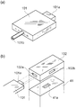
- (B) is a perspective view which shows a mode that a displacement sensor is attached to a sensor support member, and a sensor support member is attached on a slider. It is a perspective view which shows a mode that the curvature of the X-axis direction of a Y bar is measured using the X direction jig
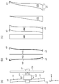
- (A) is the top view which showed a mode that the bending of Y bar
- (B) is a figure which shows the measurement data produced based on the measurement result of the bending of the Y bar measured by the displacement sensor, and the measurement result.
- (C) is a figure which shows the cutting data for cutting into a desired process area
- (A) is the top view which showed a mode that the curve of the guide rail bent in the Y-axis direction was measured using a displacement sensor.
- (B) is a figure which shows the measurement result of the bending of the guide rail measured by the said displacement sensor, and the cutting data produced based on the measurement result.
- (C) is a figure which shows the cutting data for cutting into a desired process area
- FIG. 1 shows a schematic configuration of an XY plotter type cutting plotter 1 in which a workpiece is cut in a desired shape by moving up and down in the vertical direction and moving in two orthogonal axes in a horizontal plane. .
- FIG. 1 is the positive Z-axis direction
- the lower right direction (the direction parallel to the Y bar 32 described later) on the paper surface of FIG.
- a lower left direction (a direction parallel to a guide rail 31 described later) is defined as a positive X-axis direction.
- the cutting plotter 1 includes a processing table 20 that holds the processing medium 2 fixedly, a main body frame 10 that holds the processing table 20 horizontally and serves as a mounting base for each mechanism, and an X-axis direction (front and rear) above the processing table 20.
- X-axis carriage 30 that is movably supported in a direction) and is movable in the X-axis direction by an X-axis drive mechanism 35 described later, and is supported movably in the Y-axis direction (left-right direction) along a Y-bar 32 described later.
- a cutting unit 40 that can be moved in the Y-axis direction by a Y-axis drive mechanism 45, which will be described later, and a horizontal movement of the X-axis carriage 30 and a vertical movement of an end mill 43, which will be described later, are controlled.
- the control unit 50 is configured to control cutting of the workpiece medium 2.
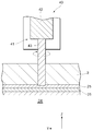
- the processing table 20 includes a support plate 21 having a flat surface, a decompression chamber 22 provided on the lower surface side of the support plate 21, and a vacuum blower capable of setting the decompression chamber 22 to a negative pressure by exhausting air from the decompression chamber 22.
- a rectangular vacuum table 24 which is provided at the center portion when viewed from above the processing table 20 and on which the sheet-like processing medium 2 can be placed and fixedly held, and covers the upper surface of the vacuum table 24
- it is configured by two felts 25 having a thickness of about 3 mm for supporting the processing medium 2 (see FIGS. 1 and 2).
- mounting portions 21 a and 21 b for mounting legs of an X-direction jig 103 and a Y-direction jig 104 to be described later are provided on the upper surface of the support board 21.
- the vacuum table 24 has a number of fine air holes (not shown) penetrating vertically.
- the air holes and the decompression chamber 22 are provided on the lower surface side of the vacuum table 24, and the upper surface of the vacuum table 24 is By adopting a configuration covered with two sheet-like felts 25, it is possible to allow air to pass through the air holes and the felts 25 in the vertical direction. Therefore, by setting the decompression chamber 22 to a negative pressure by the vacuum blower 23, the workpiece medium 2 can be vacuum-sucked and held on the vacuum table 24.
- the X-axis carriage 30 has a pair of left and right guide rails 31 and 31 provided on the upper surface of the support plate 21 so as to extend in parallel with the X-axis direction, and an X-axis carriage provided on the guide rails 31 and 31 so as to extend in the Y-axis direction.
- Y bar 32 held movably in the direction, slide blocks 33 and 34 fitted to guide rails 31 and 31, respectively, for fixing the left end and right end of Y bar 32, and Y bar 32 It is comprised by the X-axis drive mechanism 35 moved to an axial direction.
- a support rail of a linear motion bearing that is also referred to as a linear motion guide or a linear guide is used.
- the Y bar 32 is formed using an aluminum material so as to extend in a rod shape, and is supported so as to be slidable in the X-axis direction while straddling the upper side of the support board 21.
- the X-axis drive mechanism 35 includes a ball screw (not shown) disposed on the lower surface side of the processing table 20 so as to extend back and forth in parallel with the guide rail 31, a servo motor (not shown) that rotationally drives the ball screw, It consists of a ball nut fitted and supported by a ball screw and fixed to the X-axis carriage 30, and the Y bar 32 and slide blocks 33 and 34 can be moved in the X-axis direction by rotating the servo motor. It has become.
- the cutting unit 40 is fitted to a Y-axis guide rail 32a fixed to the front surface of the Y bar 32 so as to extend in the Y-axis direction, and is slidable to the left and right.
- the end mill 43 configured to cut the workpiece medium 2
- the Y-axis drive mechanism 45 capable of moving the slider 41 in the Y-axis direction
- the rotation drive unit 42 rotate the end mill 43, and the end mill 43 is rotated to the rotation drive unit.
- the cutting drive mechanism 46 is configured to be movable in the vertical direction with respect to 42.
- the slider 41 has an engagement hole 41 a on the upper surface thereof, and a carriage shape measuring mechanism 100 (detailed later) is attached to the slider 41 by fitting a protrusion of a sensor support member 102 to be described later into the engagement hole 41 a. It is possible. Further, the end mill 43 can be moved up and down with respect to the rotation drive unit 42, and the end mill 43 obtained by rotating and rotating the end mill 43 using the rotation drive unit 42 is rotated by the cutting drive mechanism 46. It is possible to perform cutting of the medium 2 by pressing and moving it 2. In addition, not only the end mill 43 but also a cutter blade or the like can be attached to and detached from the rotation drive unit 42.
- the Y-axis drive mechanism 45 includes a drive pulley (not shown) and a driven pulley (not shown) that are rotatably provided on the left end side and the right end side of the Y bar 32, and a servo motor (rotatingly driving the drive pulley). (Not shown) and an endless belt-like drive belt (not shown) wound around the drive pulley and the driven pulley, and the slider 41 is fixed to the intermediate portion of the drive belt.
- a timing belt having a large number of teeth formed on the inner peripheral surface of the drive belt, and a timing pulley is used for the drive pulley and the driven pulley to move the cutting unit 40 (moving direction, moving speed, left-right position, etc.). It can be finely controlled.
- the control unit 50 includes a cutting shape data reading unit 52, a cutting shape setting unit 53, a drive control unit 54, an input unit 55, a display unit 56, and the like.
- the cutting shape data reading unit 52 is configured to read a predetermined machining program and a desired machining shape (hereinafter referred to as machining shape data) input by the user, and transmit the machining shape data to the cutting shape setting unit 53.
- the cutting shape setting unit 53 refers to the machining shape data received from the cutting shape data reading unit 52 to create cutting data (shape data) used when cutting the workpiece medium 2 and uses the created cutting data. It transmits to the drive control part 54.
- the drive control unit 54 can control the entire apparatus including each axis driving mechanism of the cutting plotter 1, and based on the cutting data received from the cutting shape setting unit 53, the above-described X-axis driving mechanism 35, Y
- the horizontal movement of the X-axis carriage 30 and the cutting unit 40 and the vertical movement of the end mill 43 are controlled by controlling the operations of the shaft drive mechanism 45, the cutting drive mechanism 46, and the like.
- the workpiece medium 2 can be cut.
- the input unit 55 is a touch panel provided for a user to input an instruction for operating the cutting plotter 1, and the user can input a cutting procedure instruction (for example, clockwise or counterclockwise) via the input unit 55. Instructing to perform cutting, cutting speed, and cutting conditions such as the pressing force of the end mill against the work medium) and reciprocating the slider 41 in the Y-axis direction and the Y bar 32 in the X-axis direction. Thus, the shape of the guide rail 31 and the Y bar 32 can be measured (detailed later).
- the display unit 59 is used as a display that displays the cutting conditions, the cutting shape, and the operation result of the cutting plotter 1.
- a fine bend may occur in the manufacturing stage.
- some Y bars 32 have a length of about 1 m and have a curvature of about 0.9 mm.
- the cutting unit 40 cannot be moved straight in the X direction and the Y direction, and cutting is performed in the shape of the machining shape data. There arises a problem that the quality of the cutting process is deteriorated such that it cannot be performed.
- a carriage shape reading unit 51 and a carriage shape measuring mechanism 100 are provided, and a guide is provided by the carriage shape measuring mechanism 100 before the cutting plotter 1 is manufactured and shipped.
- a guide is provided by the carriage shape measuring mechanism 100 before the cutting plotter 1 is manufactured and shipped.
- the carriage shape reading unit 51 is provided in the control unit 50 as shown in FIG. 3, reads the bending of the guide rail 31 and the Y bar 32 (hereinafter referred to as carriage shape data) by the carriage shape measuring mechanism 100, and reads the read carriage.
- the shape data is configured to be transmitted to the cutting shape setting unit 53.
- the cutting shape setting unit 53 corrects the machining shape data received from the cutting shape data reading unit 52 using the carriage shape data and creates cutting data (detailed later).
- the carriage shape measuring mechanism 100 is fitted with a displacement sensor 101 that measures the bending of the guide rail 31 and the Y bar 32, and a protrusion 101 a provided on the displacement sensor 101.
- a sensor support member 102 having fitting holes 102a and 102b and projections (not shown) for mating, an X-direction jig 103 that can be arranged to extend in the Y-axis direction, and an X-axis direction. It is comprised with the Y direction jig
- the displacement sensor 101 By fitting the convex portions 101a of the displacement sensor 101 into the fitting holes 102a and 102b of the sensor support member 102, the displacement sensor 101 can be fixedly supported by the sensor support member 102, and the sensor support member 102 is also supported.
- the displacement sensor 101 and the sensor support member 102 can be fixedly supported on the slider 41 by engaging the protrusions (not shown) of the protrusions with the engagement holes 41 a of the slider 41.
- the displacement sensor 101 in the present embodiment is a contact-type displacement sensor 101, and when measuring an object, the displacement is measured by bringing the tip of a measuring unit 101b extending in a bar shape into contact with the object. It is possible.
- the displacement sensor used here is not limited to the contact type displacement sensor 101.
- a non-contact type displacement sensor such as a dial gauge type, an eddy current type, an optical type, an air sensor or the like may be used. Good.
- the X-direction jig 103 has a hole 103 a for fixing the Y-direction jig 104, and a convex portion provided at one end extending in the longitudinal direction of the Y-direction jig 104 (see FIG. 6). 4), the Y-direction jig 104 can be fixed to the X-direction jig 103 as shown in FIG.
- the jigs 103 and 104 have legs at both end portions extending in the longitudinal direction, and the lower surfaces of the rod-like portions extending in the longitudinal direction of the jigs 103 and 104 do not come into contact with the workpiece medium 2 and the support plate 21. ing.
- the tip of the measurement unit 101b of the displacement sensor 101 is in contact with a surface (side surface) orthogonal to the XY plane of the rod-shaped portion extending in the longitudinal direction of the jigs 103 and 104.
- a method of measuring the bending of the guide rail 31 and the Y bar 32 using the cutting plotter 1 and the carriage shape measuring mechanism 100 configured as described above and reflecting the measurement results in actual cutting will be described below.
- a method for measuring the bending of the Y bar 32 provided extending in the Y-axis direction and reflecting the measurement result will be described.
- the protrusion (not shown) of the sensor support member 102 is the engagement hole 41a of the slider 41
- the projection 101a of the displacement sensor 101 is the engagement hole of the sensor support member 102.
- the displacement sensor 101 is fitted to 102a so that the tip of the measuring unit 101b faces the positive direction of the X axis. Then, as shown in FIG.
- the X-direction jig 103 is arranged so that the leg portion provided at one end thereof is placed on the upper surface of the placement portion 21 a, and the distal end of the measurement portion 101 b of the displacement sensor 101. Is finely adjusted so as to contact the side surface of the X-direction jig 103.
- the input unit 55 is operated to reciprocate the slider 41 in the Y-axis direction to measure the bending of the Y bar 32. Do.
- the displacement sensor 101 fixedly supported by the slider 41 also reciprocates in the Y-axis direction.
- the displacement sensor 101 has a long left end portion as shown in FIG.
- the Y bar shape measurement result 121 in which the right end portion is bent in the negative direction of the X axis by the length e2 is output as carriage shape data.
- the carriage shape reading unit 51 reads the carriage shape data (Y bar shape measurement result 121) and transmits it to the cutting shape setting unit 53.
- the machining shape data (desired machining shape) is a straight line 122 parallel to the Y-axis direction as shown in FIG. 7B
- the cutting shape setting unit 53 calculates the displacement of the bend in the X-axis direction of the Y bar shape measurement result 121 with respect to the intended straight line 122, the left end portion is the length e1, and the right end portion Cutting data 123 bent in the positive direction of the X axis by the length e2.
- the bending of the Y bar 32 is offset by the cutting data 123 and can be cut like a straight line 122. .
- the machining shape data (desired machining shape)
- creating the cutting data 123 it becomes possible to perform cutting without being affected by the bending of the Y bar 32.
- cutting data 132 as shown in FIG. 7C is created and cut, and as a result, cutting can be performed as in the region 131.
- the desired machining area is a right triangle such as the area 161, the cutting data 162 is created and cut, so that the cutting can be performed like the area 161 as a result.
- the leg portion is arranged so as to be placed on the placement portion 21b (see FIG. 1), and the position is finely adjusted so that the tip of the measurement portion 101b of the displacement sensor 101 contacts the side surface of the Y-direction jig 104. .
- the guide rail 31 is bent at the upper end portion in the Y-axis negative direction by the length e3 and the lower end portion by the length e4 in the Y-axis positive direction.
- the input unit 55 is operated to reciprocate the slider 41 in the X-axis direction and measure the bending of the guide rail 31.
- the displacement sensor 101 fixedly supported by the slider 41 also reciprocates in the X-axis direction.
- the displacement sensor 101 has a long upper end as shown in FIG.
- a guide rail shape measurement result 141 having a shape in which the lower end portion is bent in the Y-axis positive direction by the length e4 by the length e3 is output as carriage shape data.
- the carriage shape reading unit 51 reads the carriage shape data (guide rail shape measurement result 141) and transmits it to the cutting shape setting unit 53.
- the cutting shape setting unit 53 calculates the displacement of the bending in the Y-axis direction of the guide rail shape measurement result 141 with respect to the straight line 142, and the upper end portion has the length e3.
- Cutting data 143 is created in which the lower end portion is bent in the Y-axis negative direction only by the length e4.
- machining shape data (desired machining shape) and creating the cutting data 143
- a desired machining area can be obtained.
- the desired processing area is a right triangle such as the area 171
- the cutting data 172 is created and cut, and as a result, the cutting can be performed like the area 171.
- the displacement sensor 101 is attached to the slider 41, and the carriage shape data acquired using the jigs 103 and 104 is held in the carriage shape reading unit 51. After the carriage shape data is held, cutting is always performed.
- the shape setting unit 53 operates to correct the machining shape data (desired machining shape) with the carriage shape data for cutting.
- the carriage shape data can be updated as needed by using the carriage shape measuring mechanism 100 as described above. For example, when the shape of the guide rail 31 and the Y bar 32 is changed for a long time using the cutting plotter 1, the carriage shape data of the carriage shape reading unit 51 is updated again using the carriage shape measuring mechanism 100.
- the bending of the guide rail 31 and the Y bar 32 is measured by the carriage shape measuring mechanism 100, and the machining shape data (desired machining shape) is corrected using the measurement result.
- the machining shape data (desired machining shape) is corrected using the measurement result.
- the carriage shape data of the carriage shape reading unit 51 is updated using the carriage shape measuring mechanism 100 before the cutting plotter 1 is manufactured and before shipment is shown.
- the carriage shape data is updated.
- the timing is not limited to before the production of the cutting plotter 1 and before shipment. For example, the timing may be executed every time the power switch is turned on, or may be executed during maintenance of the cutting plotter 1.
- the displacement sensor must be used as a device for measuring the bending.
- a laser side length measuring device, a straightness measuring device, or the like may be used.
- the present invention is characterized in that the cutting is performed by correcting the bending of the guide rail 31 and the Y bar 32 using the carriage shape measuring mechanism 100 and the carriage shape reading unit 51.
- the present invention can be applied to other types of cutting plotters or printer apparatuses such as a work medium drive type.
- the machining surface of the workpiece medium 2 is transverse (parallel to the XY plane).
- the present invention can also be applied to a cutting plotter of the type in which the end mill 43 is pressed from the lateral direction and is cut and processed by suction.
- Cutting plotter Work medium 20 Work table (medium support means) 31 Guide rail (first guide rail) 32 Y bar (second guide rail) 41 Slider (carriage) 43 End mill (processing tool) 50 Control unit (processing control means) 101 Displacement sensor (first direction deviation detection means, second direction deviation detection means) 103 X direction jig (second direction deviation detecting means) 104 Y direction jig (first direction deviation detecting means)
Landscapes
- Engineering & Computer Science (AREA)
- Mechanical Engineering (AREA)
- Physics & Mathematics (AREA)
- Manufacturing & Machinery (AREA)
- General Physics & Mathematics (AREA)
- Automation & Control Theory (AREA)
- Human Computer Interaction (AREA)
- Life Sciences & Earth Sciences (AREA)
- Forests & Forestry (AREA)
- Control Of Cutting Processes (AREA)
- Manufacture Or Reproduction Of Printing Formes (AREA)
- Machine Tool Sensing Apparatuses (AREA)
- Numerical Control (AREA)
- Manipulator (AREA)
- Automatic Control Of Machine Tools (AREA)
Abstract
Description
2 被加工媒体
20 加工テーブル(媒体支持手段)
31 ガイドレール(第1ガイドレール)
32 Yバー(第2ガイドレール)
41 スライダ(キャリッジ)
43 エンドミル(加工具)
50 コントロールユニット(加工制御手段)
101 変位センサ(第1方向ずれ検出手段、第2方向ずれ検出手段)
103 X方向治具(第2方向ずれ検出手段)
104 Y方向治具(第1方向ずれ検出手段)
Claims (3)
- シート状の被加工媒体を支持する支持面を有する媒体支持手段と、
前記媒体支持手段に前記支持面に対して平行な第1方向に延びて設けられた第1ガイドレールと、
前記第1ガイドレールに沿って前記第1方向に移動可能に取り付けられ、前記支持面に対して平行且つ前記第1方向に交差する第2方向に延びて設けられた第2ガイドレールと、
前記第2ガイドレールに沿って前記第2方向に移動可能に取り付けられたキャリッジと、
前記キャリッジに前記支持面に対して垂直な第3方向に移動可能に取り付けられ、前記被加工媒体の切削加工を行う加工具と、
前記第2ガイドレールを前記第1ガイドレールに沿って前記第1方向に移動させる制御と、前記キャリッジを前記第2ガイドレールに沿って前記第2方向に移動させる制御と、前記加工具を前記キャリッジに対して前記第3方向に移動させる制御とを行って、前記加工具により前記被加工媒体を切削加工させる加工制御手段とを備えたカッティングプロッタにおいて、
前記キャリッジを前記第2ガイドレールに沿って前記第2方向に移動させたときの前記第2ガイドレールに対する前記キャリッジの移動経路が所期の移動経路に対して前記第2方向と直交する方向にずれるずれの大きさを示す第2ガイドレールずれ量を測定する第2方向ずれ検出手段を備え、
前記加工制御手段は、前記第2ガイドレール上での前記キャリッジの移動制御において前記第2ガイドレールずれ量を補正するように前記第1ガイドレール上での前記第2ガイドレールの移動制御を加えた制御を行うことを特徴とするカッティングプロッタ。 - 前記第2ガイドレールを前記第1ガイドレールに沿って前記第1方向に移動させたときの前記第1ガイドレールに対する前記第2ガイドレールの移動経路が所期の移動経路に対して前記第1方向と直交する方向にずれるずれの大きさを示す第1ガイドレールずれ量を測定する第1方向ずれ検出手段を備え、
前記加工制御手段は、前記第1ガイドレール上での前記第2ガイドレールの移動制御において前記第1ガイドレールずれ量を補正するように前記第2ガイドレール上での前記キャリッジの移動制御を加えた制御を行うことを特徴とする請求項1に記載のカッティングプロッタ。 - 前記第1及び第2ガイドレールは、直線上に延びて設けられ、
前記第1方向ずれ検出手段は、前記第1ガイドレールの曲がりを測定し、
前記第2方向ずれ検出手段は、前記第2ガイドレールの曲がりを測定することを特徴とする請求項1または2に記載のカッティングプロッタ。
Priority Applications (3)
| Application Number | Priority Date | Filing Date | Title |
|---|---|---|---|
| CN201080040944.1A CN102497956B (zh) | 2009-07-14 | 2010-05-25 | 切绘机 |
| EP10799554.0A EP2455184B1 (en) | 2009-07-14 | 2010-05-25 | Cutting plotter |
| US13/348,982 US8757941B2 (en) | 2009-07-14 | 2012-01-12 | Cutting plotter |
Applications Claiming Priority (2)
| Application Number | Priority Date | Filing Date | Title |
|---|---|---|---|
| JP2009-166046 | 2009-07-14 | ||
| JP2009166046A JP5606697B2 (ja) | 2009-07-14 | 2009-07-14 | カッティングプロッタ |
Related Child Applications (1)
| Application Number | Title | Priority Date | Filing Date |
|---|---|---|---|
| US13/348,982 Continuation US8757941B2 (en) | 2009-07-14 | 2012-01-12 | Cutting plotter |
Publications (1)
| Publication Number | Publication Date |
|---|---|
| WO2011007490A1 true WO2011007490A1 (ja) | 2011-01-20 |
Family
ID=43449102
Family Applications (1)
| Application Number | Title | Priority Date | Filing Date |
|---|---|---|---|
| PCT/JP2010/003480 Ceased WO2011007490A1 (ja) | 2009-07-14 | 2010-05-25 | カッティングプロッタ |
Country Status (6)
| Country | Link |
|---|---|
| US (1) | US8757941B2 (ja) |
| EP (1) | EP2455184B1 (ja) |
| JP (1) | JP5606697B2 (ja) |
| KR (1) | KR20120027533A (ja) |
| CN (1) | CN102497956B (ja) |
| WO (1) | WO2011007490A1 (ja) |
Families Citing this family (18)
| Publication number | Priority date | Publication date | Assignee | Title |
|---|---|---|---|---|
| JP6285093B2 (ja) * | 2012-09-07 | 2018-02-28 | 株式会社ミマキエンジニアリング | インクジェットプリンタ及び印刷方法 |
| DE102013015792A1 (de) | 2012-10-31 | 2014-04-30 | Heidelberger Druckmaschinen Ag | Vorrichtung und Verfahren zum Erzeugen von Rilllinien |
| JP2014124757A (ja) * | 2012-12-27 | 2014-07-07 | Mitsuboshi Diamond Industrial Co Ltd | 加工装置 |
| US10245803B2 (en) * | 2013-03-13 | 2019-04-02 | Xerox Corporation | Apparatus, system and method for cutting and creasing media |
| CN103706850A (zh) * | 2013-12-25 | 2014-04-09 | 镇江市大兴机械制造有限公司 | 一种新型铣床 |
| CN104890063B (zh) * | 2015-06-23 | 2017-06-23 | 安阳市凤舞木工机械有限公司 | 一种多功能木料加工设备 |
| NL2015103B1 (nl) * | 2015-07-07 | 2017-01-31 | Securo B V | Inrichting en werkwijze voor het bewerken van een flexibel vel. |
| CN105150290A (zh) * | 2015-08-13 | 2015-12-16 | 王永志 | 一种建筑木板自动钻孔装置 |
| CN105290477A (zh) * | 2015-10-12 | 2016-02-03 | 广西平果恒通铜铝门业有限公司 | 一种铝材板洗槽机 |
| JP1571646S (ja) * | 2016-09-09 | 2017-03-13 | ||
| KR101937028B1 (ko) * | 2017-06-02 | 2019-01-09 | 안영재 | 아크릴판 절삭장치 및 이를 이용한 아크릴판 절삭방법 |
| CN109093176B (zh) * | 2018-07-10 | 2020-01-21 | 常德瑞齐隆科技发展有限公司 | 一种机械设备生产用具有角料收集功能的切割装置 |
| USD971278S1 (en) * | 2019-01-25 | 2022-11-29 | Marshalltown Company | Portable scoring and cutting machine |
| US11826956B2 (en) | 2019-10-04 | 2023-11-28 | Kana Holdings, LLC | System and method for providing three-dimensional features on large format print products |
| US20230001599A1 (en) * | 2019-12-12 | 2023-01-05 | Cricut, Inc. | Matless Cutting Machine and Methods |
| US20240353211A1 (en) * | 2023-04-20 | 2024-10-24 | Roy Blanchette | Trim Block Measuring Guide Device |
| USD1025203S1 (en) * | 2023-09-07 | 2024-04-30 | Beaver Technology (Shenzhen) Co., Ltd. | Cutting machine |
| CN117742239B (zh) * | 2024-02-19 | 2024-05-14 | 南京超颖新能源科技有限公司 | 机床的垂直矫正系统及矫正方法 |
Citations (3)
| Publication number | Priority date | Publication date | Assignee | Title |
|---|---|---|---|---|
| JP2004148745A (ja) | 2002-10-31 | 2004-05-27 | Seiko Epson Corp | ヘッド移動データ生成方法および印刷方法 |
| JP2009050978A (ja) * | 2007-08-28 | 2009-03-12 | Mimaki Engineering Co Ltd | カッティングプロッタ |
| JP2009068957A (ja) * | 2007-09-12 | 2009-04-02 | Mitsutoyo Corp | 真直度測定装置、厚み変動測定装置及び直交度測定装置 |
Family Cites Families (9)
| Publication number | Priority date | Publication date | Assignee | Title |
|---|---|---|---|---|
| CN1025578C (zh) * | 1991-05-06 | 1994-08-03 | 华中理工大学 | 闭环定位装置 |
| DE4134371A1 (de) * | 1991-10-17 | 1993-04-22 | Zeiss Carl Fa | Verfahren zur messung der effektiven momentanposition eines von einem schlitten getragenen tastelementes bzw. werkzeugs |
| JPH06312347A (ja) * | 1993-04-28 | 1994-11-08 | Ando Electric Co Ltd | Nc加工機 |
| JP2002333923A (ja) * | 2001-05-10 | 2002-11-22 | Yokogawa Electric Corp | モータの精度検査装置 |
| US6949733B2 (en) * | 2003-03-10 | 2005-09-27 | Asm Technology Singapore Pte Ltd | Determination of a movable gantry position including a dual measurement module |
| CN2633936Y (zh) * | 2003-06-26 | 2004-08-18 | 上海理工大学附属二厂 | 非接触式两向钢轨直线自动测量装置 |
| DE102005003321A1 (de) * | 2005-01-18 | 2006-07-27 | Carl Zeiss Industrielle Messtechnik Gmbh | Verfahren zum Bestimmen einer Raumkoordinate eines Messpunktes an einem Messobjekt sowie entsprechendes Koordinatenmessgerät |
| DE102006044358A1 (de) * | 2006-09-20 | 2008-04-03 | Etel S.A. | Positioniereinrichtung in Portalbauweise |
| CN101105389A (zh) * | 2007-05-30 | 2008-01-16 | 中国人民解放军第二炮兵装备研究院第四研究所 | 高精度非接触三维面型测量装置 |
-
2009
- 2009-07-14 JP JP2009166046A patent/JP5606697B2/ja active Active
-
2010
- 2010-05-25 WO PCT/JP2010/003480 patent/WO2011007490A1/ja not_active Ceased
- 2010-05-25 CN CN201080040944.1A patent/CN102497956B/zh not_active Expired - Fee Related
- 2010-05-25 KR KR20127001069A patent/KR20120027533A/ko not_active Ceased
- 2010-05-25 EP EP10799554.0A patent/EP2455184B1/en not_active Withdrawn - After Issue
-
2012
- 2012-01-12 US US13/348,982 patent/US8757941B2/en active Active
Patent Citations (3)
| Publication number | Priority date | Publication date | Assignee | Title |
|---|---|---|---|---|
| JP2004148745A (ja) | 2002-10-31 | 2004-05-27 | Seiko Epson Corp | ヘッド移動データ生成方法および印刷方法 |
| JP2009050978A (ja) * | 2007-08-28 | 2009-03-12 | Mimaki Engineering Co Ltd | カッティングプロッタ |
| JP2009068957A (ja) * | 2007-09-12 | 2009-04-02 | Mitsutoyo Corp | 真直度測定装置、厚み変動測定装置及び直交度測定装置 |
Non-Patent Citations (1)
| Title |
|---|
| See also references of EP2455184A4 |
Also Published As
| Publication number | Publication date |
|---|---|
| EP2455184B1 (en) | 2017-03-15 |
| JP2011020202A (ja) | 2011-02-03 |
| US20120103154A1 (en) | 2012-05-03 |
| CN102497956B (zh) | 2014-07-23 |
| US8757941B2 (en) | 2014-06-24 |
| CN102497956A (zh) | 2012-06-13 |
| KR20120027533A (ko) | 2012-03-21 |
| JP5606697B2 (ja) | 2014-10-15 |
| EP2455184A4 (en) | 2013-09-04 |
| EP2455184A1 (en) | 2012-05-23 |
Similar Documents
| Publication | Publication Date | Title |
|---|---|---|
| JP5606697B2 (ja) | カッティングプロッタ | |
| TWI332423B (en) | Method and apparatus for machining work by cutting tool | |
| JP5333816B2 (ja) | ガラス板の切線加工装置及び切線加工方法 | |
| JPWO2008126502A1 (ja) | スクライブ装置及びスクライブ方法 | |
| KR101209826B1 (ko) | 정밀부품 면삭가공을 위한 밀링머신용 지그 | |
| KR101082972B1 (ko) | 양두 밀링 가공 장치 | |
| US11471961B2 (en) | Method for machining plate material by using linear saw and numerical control saw machine apparatus | |
| CN101720266B (zh) | 手持式工具机 | |
| JP2008126322A (ja) | バイト加工方法及びバイト加工装置 | |
| KR101365376B1 (ko) | 스크라이브 장치 | |
| JP6940663B1 (ja) | 放電加工装置およびセンサユニット | |
| JP5670032B2 (ja) | カッティングプロッタ | |
| CN207508425U (zh) | 数控锯床设备及用该数控锯床设备加工的板材 | |
| JP5597328B2 (ja) | カッティングプロッタ、およびそれを用いたカッティング方法 | |
| JPH10296339A (ja) | 曲げ加工方法およびその装置 | |
| CN118081868A (zh) | 裁剪机及裁剪刀的磨损程度取得方法 | |
| CN106270770B (zh) | 手持式往复锯 | |
| JP2009160670A (ja) | カット条件の入力支援プログラム、入力支援方法、及びカッティングプロッタ | |
| CN222830819U (zh) | 圆钢切断机 | |
| JP5702972B2 (ja) | 切断装置 | |
| JP5016898B2 (ja) | バイト加工装置 | |
| JP2004284000A (ja) | 真直度制御ステージ | |
| JP2019171392A (ja) | パネルベンダー | |
| JP2004090054A (ja) | レーザ溶接方法およびレーザ溶接装置 | |
| JP2002036023A (ja) | プレス機におけるスライド下面修正方法と装置 |
Legal Events
| Date | Code | Title | Description |
|---|---|---|---|
| WWE | Wipo information: entry into national phase |
Ref document number: 201080040944.1 Country of ref document: CN |
|
| 121 | Ep: the epo has been informed by wipo that ep was designated in this application |
Ref document number: 10799554 Country of ref document: EP Kind code of ref document: A1 |
|
| REEP | Request for entry into the european phase |
Ref document number: 2010799554 Country of ref document: EP |
|
| WWE | Wipo information: entry into national phase |
Ref document number: 2010799554 Country of ref document: EP |
|
| ENP | Entry into the national phase |
Ref document number: 20127001069 Country of ref document: KR Kind code of ref document: A |
|
| NENP | Non-entry into the national phase |
Ref country code: DE |