WO2011004898A1 - 光拡散フィルムおよびそれを含む液晶表示装置 - Google Patents
光拡散フィルムおよびそれを含む液晶表示装置 Download PDFInfo
- Publication number
- WO2011004898A1 WO2011004898A1 PCT/JP2010/061729 JP2010061729W WO2011004898A1 WO 2011004898 A1 WO2011004898 A1 WO 2011004898A1 JP 2010061729 W JP2010061729 W JP 2010061729W WO 2011004898 A1 WO2011004898 A1 WO 2011004898A1
- Authority
- WO
- WIPO (PCT)
- Prior art keywords
- light
- film
- liquid crystal
- resin
- crystal display
- Prior art date
Links
Images


Classifications
-
- G—PHYSICS
- G02—OPTICS
- G02B—OPTICAL ELEMENTS, SYSTEMS OR APPARATUS
- G02B5/00—Optical elements other than lenses
- G02B5/02—Diffusing elements; Afocal elements
- G02B5/0205—Diffusing elements; Afocal elements characterised by the diffusing properties
- G02B5/0236—Diffusing elements; Afocal elements characterised by the diffusing properties the diffusion taking place within the volume of the element
- G02B5/0242—Diffusing elements; Afocal elements characterised by the diffusing properties the diffusion taking place within the volume of the element by means of dispersed particles
-
- G—PHYSICS
- G02—OPTICS
- G02B—OPTICAL ELEMENTS, SYSTEMS OR APPARATUS
- G02B5/00—Optical elements other than lenses
- G02B5/02—Diffusing elements; Afocal elements
- G02B5/0205—Diffusing elements; Afocal elements characterised by the diffusing properties
- G02B5/021—Diffusing elements; Afocal elements characterised by the diffusing properties the diffusion taking place at the element's surface, e.g. by means of surface roughening or microprismatic structures
- G02B5/0221—Diffusing elements; Afocal elements characterised by the diffusing properties the diffusion taking place at the element's surface, e.g. by means of surface roughening or microprismatic structures the surface having an irregular structure
-
- G—PHYSICS
- G02—OPTICS
- G02B—OPTICAL ELEMENTS, SYSTEMS OR APPARATUS
- G02B5/00—Optical elements other than lenses
- G02B5/04—Prisms
- G02B5/045—Prism arrays
-
- G—PHYSICS
- G02—OPTICS
- G02B—OPTICAL ELEMENTS, SYSTEMS OR APPARATUS
- G02B6/00—Light guides; Structural details of arrangements comprising light guides and other optical elements, e.g. couplings
- G02B6/0001—Light guides; Structural details of arrangements comprising light guides and other optical elements, e.g. couplings specially adapted for lighting devices or systems
- G02B6/0011—Light guides; Structural details of arrangements comprising light guides and other optical elements, e.g. couplings specially adapted for lighting devices or systems the light guides being planar or of plate-like form
- G02B6/0013—Means for improving the coupling-in of light from the light source into the light guide
- G02B6/0023—Means for improving the coupling-in of light from the light source into the light guide provided by one optical element, or plurality thereof, placed between the light guide and the light source, or around the light source
- G02B6/0025—Diffusing sheet or layer; Prismatic sheet or layer
-
- G—PHYSICS
- G02—OPTICS
- G02B—OPTICAL ELEMENTS, SYSTEMS OR APPARATUS
- G02B6/00—Light guides; Structural details of arrangements comprising light guides and other optical elements, e.g. couplings
- G02B6/0001—Light guides; Structural details of arrangements comprising light guides and other optical elements, e.g. couplings specially adapted for lighting devices or systems
- G02B6/0011—Light guides; Structural details of arrangements comprising light guides and other optical elements, e.g. couplings specially adapted for lighting devices or systems the light guides being planar or of plate-like form
- G02B6/0033—Means for improving the coupling-out of light from the light guide
- G02B6/005—Means for improving the coupling-out of light from the light guide provided by one optical element, or plurality thereof, placed on the light output side of the light guide
- G02B6/0051—Diffusing sheet or layer
-
- G—PHYSICS
- G02—OPTICS
- G02B—OPTICAL ELEMENTS, SYSTEMS OR APPARATUS
- G02B6/00—Light guides; Structural details of arrangements comprising light guides and other optical elements, e.g. couplings
- G02B6/0001—Light guides; Structural details of arrangements comprising light guides and other optical elements, e.g. couplings specially adapted for lighting devices or systems
- G02B6/0011—Light guides; Structural details of arrangements comprising light guides and other optical elements, e.g. couplings specially adapted for lighting devices or systems the light guides being planar or of plate-like form
- G02B6/0033—Means for improving the coupling-out of light from the light guide
- G02B6/005—Means for improving the coupling-out of light from the light guide provided by one optical element, or plurality thereof, placed on the light output side of the light guide
- G02B6/0053—Prismatic sheet or layer; Brightness enhancement element, sheet or layer
-
- G—PHYSICS
- G02—OPTICS
- G02F—OPTICAL DEVICES OR ARRANGEMENTS FOR THE CONTROL OF LIGHT BY MODIFICATION OF THE OPTICAL PROPERTIES OF THE MEDIA OF THE ELEMENTS INVOLVED THEREIN; NON-LINEAR OPTICS; FREQUENCY-CHANGING OF LIGHT; OPTICAL LOGIC ELEMENTS; OPTICAL ANALOGUE/DIGITAL CONVERTERS
- G02F1/00—Devices or arrangements for the control of the intensity, colour, phase, polarisation or direction of light arriving from an independent light source, e.g. switching, gating or modulating; Non-linear optics
- G02F1/01—Devices or arrangements for the control of the intensity, colour, phase, polarisation or direction of light arriving from an independent light source, e.g. switching, gating or modulating; Non-linear optics for the control of the intensity, phase, polarisation or colour
- G02F1/13—Devices or arrangements for the control of the intensity, colour, phase, polarisation or direction of light arriving from an independent light source, e.g. switching, gating or modulating; Non-linear optics for the control of the intensity, phase, polarisation or colour based on liquid crystals, e.g. single liquid crystal display cells
- G02F1/133—Constructional arrangements; Operation of liquid crystal cells; Circuit arrangements
- G02F1/1333—Constructional arrangements; Manufacturing methods
- G02F1/1335—Structural association of cells with optical devices, e.g. polarisers or reflectors
- G02F1/133504—Diffusing, scattering, diffracting elements
-
- G—PHYSICS
- G02—OPTICS
- G02F—OPTICAL DEVICES OR ARRANGEMENTS FOR THE CONTROL OF LIGHT BY MODIFICATION OF THE OPTICAL PROPERTIES OF THE MEDIA OF THE ELEMENTS INVOLVED THEREIN; NON-LINEAR OPTICS; FREQUENCY-CHANGING OF LIGHT; OPTICAL LOGIC ELEMENTS; OPTICAL ANALOGUE/DIGITAL CONVERTERS
- G02F1/00—Devices or arrangements for the control of the intensity, colour, phase, polarisation or direction of light arriving from an independent light source, e.g. switching, gating or modulating; Non-linear optics
- G02F1/01—Devices or arrangements for the control of the intensity, colour, phase, polarisation or direction of light arriving from an independent light source, e.g. switching, gating or modulating; Non-linear optics for the control of the intensity, phase, polarisation or colour
- G02F1/13—Devices or arrangements for the control of the intensity, colour, phase, polarisation or direction of light arriving from an independent light source, e.g. switching, gating or modulating; Non-linear optics for the control of the intensity, phase, polarisation or colour based on liquid crystals, e.g. single liquid crystal display cells
- G02F1/133—Constructional arrangements; Operation of liquid crystal cells; Circuit arrangements
- G02F1/1333—Constructional arrangements; Manufacturing methods
- G02F1/1335—Structural association of cells with optical devices, e.g. polarisers or reflectors
- G02F1/1336—Illuminating devices
- G02F1/133602—Direct backlight
- G02F1/133606—Direct backlight including a specially adapted diffusing, scattering or light controlling members
-
- G—PHYSICS
- G02—OPTICS
- G02F—OPTICAL DEVICES OR ARRANGEMENTS FOR THE CONTROL OF LIGHT BY MODIFICATION OF THE OPTICAL PROPERTIES OF THE MEDIA OF THE ELEMENTS INVOLVED THEREIN; NON-LINEAR OPTICS; FREQUENCY-CHANGING OF LIGHT; OPTICAL LOGIC ELEMENTS; OPTICAL ANALOGUE/DIGITAL CONVERTERS
- G02F1/00—Devices or arrangements for the control of the intensity, colour, phase, polarisation or direction of light arriving from an independent light source, e.g. switching, gating or modulating; Non-linear optics
- G02F1/01—Devices or arrangements for the control of the intensity, colour, phase, polarisation or direction of light arriving from an independent light source, e.g. switching, gating or modulating; Non-linear optics for the control of the intensity, phase, polarisation or colour
- G02F1/13—Devices or arrangements for the control of the intensity, colour, phase, polarisation or direction of light arriving from an independent light source, e.g. switching, gating or modulating; Non-linear optics for the control of the intensity, phase, polarisation or colour based on liquid crystals, e.g. single liquid crystal display cells
- G02F1/133—Constructional arrangements; Operation of liquid crystal cells; Circuit arrangements
- G02F1/1333—Constructional arrangements; Manufacturing methods
- G02F1/1335—Structural association of cells with optical devices, e.g. polarisers or reflectors
- G02F1/13356—Structural association of cells with optical devices, e.g. polarisers or reflectors characterised by the placement of the optical elements
- G02F1/133562—Structural association of cells with optical devices, e.g. polarisers or reflectors characterised by the placement of the optical elements on the viewer side
Definitions
- the present invention relates to a light diffusion film and a liquid crystal display device including the same.
- liquid crystal display devices In recent years, the use of liquid crystal display devices is rapidly advancing and is used in mobile phones, personal computer monitors, televisions, liquid crystal projectors, and the like.
- a liquid crystal display device operates a liquid crystal in a display mode such as a TN (Twisted Nematic) mode, a VA (Vertical Alignment) mode, an IPS (In-Plane Switching) mode, and electrically transmits light passing through the liquid crystal.
- a display mode such as a TN (Twisted Nematic) mode, a VA (Vertical Alignment) mode, an IPS (In-Plane Switching) mode, and electrically transmits light passing through the liquid crystal.
- TN Transmission Nematic
- VA Very Alignment
- IPS In-Plane Switching
- the liquid crystal display device has a viewing angle dependency problem in that when the display screen is viewed from an oblique direction, the display characteristics deteriorate due to a decrease in contrast or a gradation inversion phenomenon in which the brightness is reversed in gradation display. .
- a light diffusing film having a high haze light diffusing layer obtained by coating a resin containing fine particles on a transparent substrate and curing is used to widen the viewing angle (for example, JP2007-94369-A and JP2000-352607-A). ).
- a light diffusing film has too high light diffusibility, so that the contrast of the display image is lowered.
- a light diffusion film containing fine particles in the resin coating layer and having fine irregularities on the surface of the resin coating layer is also known (for example, JP2008-152268-A and JP2000-121809-A).
- JP2008-152268-A and JP2000-121809-A have a low light diffusibility and cannot sufficiently widen the viewing angle.
- An object of the present invention is to provide a light diffusion film having a high front contrast and a wide viewing angle without causing scintillation, and a display device equipped with the light diffusion film.
- a light diffusing film comprising a base film, a translucent resin and a translucent fine particle dispersed in the translucent resin, and a light diffusing layer having a flat surface
- the translucent fine particles have an average particle size of 0.5 ⁇ m or more and less than 20 ⁇ m
- the content of the translucent fine particles is 25 parts by weight or more and 60 parts by weight or less with respect to 100 parts by weight of the translucent resin
- the refractive index of the translucent fine particles is larger than the refractive index of the translucent resin
- the difference between the refractive index of the translucent fine particles and the refractive index of the translucent resin is 0.04 or more and 0.2 or less
- the light diffusion layer has a thickness of 1 to 3 times the average particle diameter of the light-transmitting fine particles.
- the first polarizing plate and the second polarizing plate are liquid crystal display devices arranged such that their transmission axes have a crossed Nicols relationship, wherein the light diffusion film is [1] to [3 ]
- the liquid crystal display device which is a light-diffusion film in any one of.
- the light deflecting means includes two prism films each having a plurality of linear prism portions having ridge lines on the light emitting side at a predetermined interval on the light emitting surface side, and one prism film is the linear prism.
- the other prism film is arranged such that the direction of the ridgeline of the linear prism is substantially parallel to the transmission axis of the first polarizing plate, and the direction of the ridgeline of the linear prism is the transmission axis of the second polarizing plate.
- the liquid crystal display device according to [4] or [5] which is disposed so as to be substantially parallel to the surface.
- the average particle diameter of the light-transmitting fine particles is a weight average particle diameter that can be stopped by Coulter Multisizer (manufactured by Beckman Coulter, Inc.) based on the Coulter principle (pore electrical resistance method).
- the “light emitting side” is a side from which light incident from a light source such as a backlight is emitted when a light diffusion film or the like is installed in a liquid crystal display device (opposite side of the light source). It is the side close to. Conversely, the side on which light is incident from a light source such as a backlight may be referred to as the “light incident side”.
- substantially parallel to the transmission axis of the first polarizing plate means an angle with respect to the transmission axis when parallel to the transmission axis of the first polarizing plate and within a range not impairing the effects of the present invention. (For example, 15 degrees or less) is included, and the case where it is parallel is the most preferable.
- substantially parallel to the transmission axis of the second polarizing plate means that the transmission axis is parallel to the transmission axis of the second polarizing plate and within a range not impairing the effects of the present invention. The meaning includes the case of having an angle (for example, 15 ° or less), and the case of being parallel is the most preferable.
- the light diffusing film 7 in FIG. 1 includes a light transmissive resin 721 and light transmissive fine particles 722 dispersed in the light transmissive resin on one surface side of a base film 71, and a light diffusing layer 72 having a flat surface. Are laminated.
- the translucent fine particles 722 used here have an average particle size of 0.5 ⁇ m or more and less than 20 ⁇ m, and the blending amount in the translucent resin 721 is 25 parts by weight or more and 60 parts by weight with respect to 100 parts by weight of the translucent resin. Or less.
- the average particle size and blending amount of the translucent resin 721 within the above ranges, excellent light diffusibility can be obtained without causing a decrease in front contrast.
- high transparency of the transmitted image can be obtained.
- the preferable average particle diameter of the light-transmitting fine particles 722 is 4 to 8 ⁇ m, and the preferable blending amount is 30 to 40 parts by weight.
- the translucent fine particles 722 used in the present invention are not particularly limited as long as they have the above average particle diameter and translucency, and conventionally known ones can be used.
- organic fine particles such as acrylic resin, melamine resin, polyethylene, polystyrene, organic silicone resin, acrylic-styrene copolymer, and calcium carbonate, silica, aluminum oxide, barium carbonate, barium sulfate, titanium oxide, glass, etc.
- Inorganic fine particles and the like Each of these may be used alone or in combination with one or more other.
- Organic polymer balloons and glass hollow beads can also be used.
- the shape of the translucent fine particles may be any of a spherical shape, a flat shape, a plate shape, a needle shape, etc., but a spherical shape is particularly desirable.
- the refractive index of the translucent fine particles 722 is set larger than the refractive index of the translucent resin 721, and the difference is 0.04 or more and 0.2 or less, and the range of 0.04 to 0.15 is set. preferable.
- the difference in refractive index between the translucent fine particles 722 and the translucent resin 721 within the above range, the translucent fine particles 722 and the translucent resin 721 are made of light incident on the light diffusion layer 72. Internal scattering due to the difference in refractive index can be expressed, and the occurrence of scintillation can be suppressed.
- the translucent resin 721 used in the present invention is not particularly limited as long as it has translucency.
- ionizing radiation curable resins such as ultraviolet curable resins and electron beam curable resins, and thermosetting types. Resins, thermoplastic resins, metal alkoxides, and the like can be used. Of these, plastic resins are used as they are.
- curable resins such as ionizing radiation curable resins and thermosetting resins such as ultraviolet curable resins and electron beam curable resins
- curable resins are ionized radiation, heat, etc.
- the metal alkoxide is used after being converted into a cured product by hydrolysis, dehydration condensation or the like.
- ionizing radiation curable resins are preferably used from the viewpoint of high hardness and imparting sufficient scratch resistance to the light diffusion film provided on the display surface.
- ionizing radiation curable resins are polyfunctional acrylates such as polyhydric alcohol acrylic esters or methacrylic esters, and polyfunctional compounds synthesized from diisocyanates and polyhydric alcohols and hydroxy esters of acrylic acid or methacrylic acid.
- polyfunctional acrylates such as polyhydric alcohol acrylic esters or methacrylic esters
- urethane acrylate polyether resins having an acrylate functional group, polyester resins, epoxy resins, alkyd resins, spiroacetal resins, polybutadiene resins, polythiol polyene resins, and the like can also be used.
- a photopolymerization initiator when an ultraviolet curable resin is used, a photopolymerization initiator is added. It is preferable to use a photopolymerization initiator suitable for the resin used.
- a photopolymerization initiator radiation polymerization initiator
- benzoin such as benzoin, benzoin methyl ether, benzoin ethyl ether, benzoin isopropyl ether, benzyl methyl ketal, and alkyl ethers thereof are used.
- the amount of the photopolymerization initiator used is usually 0.5 to 20 parts by mass with respect to 100 parts by mass of the resin. The amount is preferably 1 to 5 parts by mass.
- thermosetting resin examples include thermosetting urethane resin composed of acrylic polyol and isocyanate prepolymer, phenol resin, urea melamine resin, epoxy resin, unsaturated polyester resin, and silicone resin.
- thermoplastic resin examples include cellulose derivatives such as acetylcellulose, nitrocellulose, acetylbutylcellulose, ethylcellulose and methylcellulose, vinyl acetate and copolymers thereof, vinyl chloride and copolymers thereof, vinylidene chloride and copolymers thereof and the like.
- Resin, acetal resin such as polyvinyl formal, polyvinyl butyral, acrylic resin and its copolymer, acrylic resin such as methacrylic resin and its copolymer, polystyrene resin, polyamide resin, linear polyester resin, polycarbonate resin, etc. it can.
- a silicon oxide matrix made of a silicon alkoxide material can be used. Specific examples include tetramethoxysilane and tetraethoxysilane, and a cured product in which an inorganic or organic-inorganic composite matrix is formed by hydrolysis and dehydration condensation can be used.
- the translucent resin 721 When an ionizing radiation curable resin is used as the translucent resin 721, it is necessary to irradiate the base film 71 with ionizing radiation such as ultraviolet rays and electron beams after being applied and dried.
- ionizing radiation such as ultraviolet rays and electron beams
- the substrate film 71 may be heated after being applied and dried.
- the layer thickness of the light diffusion layer 72 is 1 to 3 times the average particle diameter of the translucent fine particles 722.
- the texture of the light diffusion film 7 to be obtained becomes rough and scintillation easily occurs and the visibility of the display surface decreases. To do.
- the layer thickness of the light diffusion layer 72 is thicker than three times the average particle diameter of the light-transmitting fine particles 722, the light diffusion becomes too strong and the contrast is lowered, so that the display quality is lowered.
- the layer thickness of the light diffusion layer 72 is usually preferably 5 to 25 ⁇ m. When the thickness of the light diffusion layer 72 is less than 5 ⁇ m, sufficient scratch resistance sufficient to be provided on the display surface may not be obtained. On the other hand, when the thickness of the light diffusion layer 72 is greater than 25 ⁇ m, the light diffusion layer 72 is manufactured. The degree of curling of the light diffusing film 7 is increased, and the handleability may be deteriorated.
- any material may be used as long as it is translucent.
- glass or plastic film can be used.
- the plastic film only needs to have appropriate transparency and mechanical strength. Examples include cellulose acetate resins such as TAC (triacetyl cellulose), acrylic resins, polycarbonate resins, and polyester resins such as polyethylene terephthalate.
- the light diffusion film 7 of the present invention can be produced, for example, as follows.
- a solvent liquid such as an ionizing radiation curable resin, a thermosetting resin, a thermoplastic resin, or a metal alkoxide, in which the light transmitting fine particles 722 are dispersed, is formed on the base film 71.
- the light diffusion layer 72 having a flat surface is formed on the surface of the base film 71 so that the light-transmitting fine particles 722 do not appear on the surface of the coating film by adjusting the coating thickness.
- the dispersion of the translucent fine particles 722 in the resin liquid is preferably isotropic dispersion.
- the resin may be used as it is without adding a solvent. it can.
- a method of performing a surface treatment on the light diffusion layer 72 using a roll having a mirror mold surface is used in the manufacturing process of the light diffusion layer 72. Can do.
- the degree of flatness of the light diffusion layer 72 can be represented by external haze, and is preferably 1% or less, more preferably 0.5% or less.
- the solvent used for the resin liquid examples include alcohols such as ethanol, glycol ethers such as propylene glycol monomethyl ether, esters such as ethyl acetate and propylene glycol monomethyl ether acetate, ketones such as methyl ethyl ketone, and carbonization such as toluene.
- alcohols such as ethanol
- glycol ethers such as propylene glycol monomethyl ether
- esters such as ethyl acetate and propylene glycol monomethyl ether acetate
- ketones such as methyl ethyl ketone
- carbonization such as toluene.
- Including hydrogen and alkyl halides such as methylene chloride.
- the base film 71 may be subjected to a surface treatment before application of the resin liquid in order to improve coatability and adhesiveness with the light diffusion layer.
- a surface treatment include corona discharge treatment, glow discharge treatment, acid treatment, alkali treatment, and ultraviolet irradiation treatment.
- the base film 71 and the polarizer 61 are effectively used.
- the base film 71 is hydrophilized by acid treatment or alkali treatment.
- a gravure coating method for example, a gravure coating method, a micro gravure coating method, a roll coating method, a rod coating method, a knife coating method, an air knife coating method, a kiss coating method, and a die coating method. Etc. can be used.
- the solvent is dried by heating if necessary.
- ionizing radiation curable resin, thermosetting resin, metal alkoxide, or the like is used, the coating film is further cured by ionizing radiation and / or heat.
- the ionizing radiation species can be appropriately selected from ultraviolet rays, electron beams, near ultraviolet rays, visible light, near infrared rays, infrared rays, X-rays, etc., depending on the type of translucent resin 721, preferably ultraviolet rays and electron beams.
- ultraviolet rays are preferable because they are easy to handle and high energy can be easily obtained.
- any light source that generates ultraviolet light can be used.
- a low pressure mercury lamp, a medium pressure mercury lamp, a high pressure mercury lamp, an ultrahigh pressure mercury lamp, a carbon arc lamp, a metal halide lamp, a xenon lamp, or the like can be used.
- An ArF excimer laser, a KrF excimer laser, an excimer lamp, synchrotron radiation, or the like can also be used.
- an ultrahigh pressure mercury lamp, a high pressure mercury lamp, a low pressure mercury lamp, a carbon arc, a xenon arc, and a metal halide lamp can be preferably used.
- an electron beam can be used in the same manner.
- the electron beam is usually 50 to 1000 keV, preferably 100, emitted from various electron beam accelerators such as cockroft walton type, bandegraph type, resonance transformer type, insulated core transformer type, linear type, dynamitron type, and high frequency type.
- An electron beam having an energy of ⁇ 300 keV can be mentioned.
- the base film 71 wound in a roll shape is used. Winding the light diffusion film 7 on which the cured light diffusion layer 72 is formed, the step of applying and drying the resin solution in which the translucent fine particles 722 are dispersed, the step of curing the coating film, It is preferable to use a manufacturing method having a step of taking.
- a curable resin such as an ionizing radiation curable resin or an electron beam curable resin
- FIG. 2 Another embodiment of the light diffusion film of the present invention is shown in FIG.
- the light diffusing film 7 shown in FIG. 2 is obtained by further laminating a light transmissive resin layer 73 on a light diffusing layer 72 in which light transmissive fine particles 722 are dispersed and mixed in a light transmissive resin 721.
- the light diffusion film of the present invention preferably further has an antireflection layer on the side surface opposite to the base film of the light diffusion layer.
- the antireflection layer is a layer that is given a function by controlling the refractive index and thickness of each layer, such as by increasing the refractive index of the hard coat layer and providing a thin film of low refractive index on the hard coat layer. By making it as low as possible, it is possible to prevent external objects from being reflected on the display screen.
- FIG. 3 An example of a polarizing plate using the light diffusion film of the present invention is shown in FIG.
- a general polarizing plate has a structure in which a support film 62 is bonded to both sides of a polarizer 61.
- the polarizing plate shown in FIG. 3 uses the light diffusion film 7 of the present invention as one support film. It is a multifunctional film having a polarizing function and an antiglare (light diffusion) function. That is, the support film 62 is attached to one surface of the polarizer 61, and the light diffusion film 7 in which the light diffusion layer 72 is formed on the base film 71 is attached to the other surface.
- the polarizing plate having such a configuration is attached to the liquid crystal display device, the polarizing plate is attached to a glass substrate of the liquid crystal display panel so that the light diffusion film 7 is on the light emitting side.
- the base film 71 and the polarizer 61 may be bonded together via an adhesive layer, it is preferable to directly bond them without using an adhesive layer.
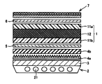
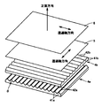
- FIG. 4 is a schematic view showing an example of a liquid crystal display device according to the present invention.
- the liquid crystal display device of FIG. 4 is a normally white mode TN liquid crystal display device, which includes a backlight device 2, a light diffusing plate 3, two prism films 4a and 4b as light deflecting means, and a first polarized light.
- the liquid crystal cell 1 in which the liquid crystal layer 12 is provided between the plate 5 and the pair of transparent substrates 11a and 11b, the second polarizing plate 6, and the light diffusion film 7 are arranged in this order.
- the 1st polarizing plate 5 and the 2nd polarizing plate 6 are arrange
- Each of the two prism films 4a and 4b has a flat surface on the light incident side, and a plurality of linear prism portions 41a and 41b formed in parallel on the surface on the light emitting side. 41a and 41b have ridge lines 42a and 42b on the light emitting side.
- the prism film 4a is arranged so that the ridge line of the linear prism part 41a is substantially parallel to the transmission axis direction of the first polarizing plate 5, and the prism film 4b is ridge line of the linear prism part 41b.
- the cross-sectional shape in the vertical cross section orthogonal to the ridge lines of the linear prism portions 41a and 41b is a triangle, and the apex angle ⁇ of the apex corresponding to the ridge line among the apexes of the triangle is 90 ° to 110 °.
- a range is preferable.
- this triangle may have either an equal side or an unequal side, and when concentrating in the front direction (normal direction of the display surface of the liquid crystal display device), It is preferable that the two sides are equal isosceles triangles.
- a plurality of linear prism portions 41a and 42a having such an isosceles triangular cross section are sequentially arranged such that the bases corresponding to the apex angle ⁇ of the triangle are adjacent to each other, and a plurality of linear prisms are arranged.
- the ridgelines 42a and 42b of the prism portions 41a and 42a are arranged so as to be substantially parallel to each other.
- the triangles of the cross-sectional shapes of the linear prism portions 41a and 42a may have a curved shape at each vertex.
- the distance between the vertices is usually in the range of 10 ⁇ m to 500 ⁇ m, and preferably in the range of 30 ⁇ m to 200 ⁇ m.
- the light emitted from the backlight device 2 is diffused by the light diffusion plate 3 and then enters the prism film 4a.
- a vertical cross section perpendicular to the transmission axis direction of the first polarizing plate 5 light incident obliquely with respect to the lower surface of the prism film 4a is emitted with its path changed in the front direction.
- the prism film 4b in the vertical cross section perpendicular to the transmission axis direction of the second polarizing plate 6, the light incident obliquely with respect to the lower surface of the prism film 4b changes its course in the front direction as described above. Is emitted. Therefore, the light passing through the two prism films 4a and 4b is condensed in the front direction in any vertical cross section, and the luminance in the front direction is improved.
- the light having directivity in the front direction is changed from circularly polarized light to linearly polarized light by the first polarizing plate 5 and enters the liquid crystal cell 1.
- the light incident on the liquid crystal cell 1 is emitted from the liquid crystal cell 1 with its polarization plane controlled for each pixel by the orientation of the liquid crystal layer 12 controlled by the electric field.
- the light emitted from the liquid crystal cell 1 is imaged by the second polarizing plate 6, passes through the light diffusion film 7, and exits to the display surface side.
- the light diffusing film is disposed so that the light diffusing layer is closer to the light emitting side than the base film.
- the directivity of the light incident on the liquid crystal cell 1 in the front direction is higher than before by the two prism films 4a and 4b.
- the brightness in the front direction is improved as compared with the conventional apparatus.
- the above-mentioned light diffusion film 7 is used, excellent light diffusibility and high transmitted image definition can be obtained without causing a decrease in front contrast.
- a liquid crystal is sealed between a pair of transparent substrates 11a and 11b arranged to face each other at a predetermined distance by a spacer (not shown), and the pair of transparent substrates 11a and 11b.
- the liquid crystal layer 12 is provided.
- a transparent electrode and an alignment film are laminated on each of the pair of transparent substrates 11a and 11b, and the liquid crystal is formed by applying a voltage based on display data between the transparent electrodes.
- the display method of the liquid crystal cell 1 is the TN method, but a display method such as an IPS method or a VA method may be adopted.
- the backlight device 2 includes a rectangular parallelepiped case 21 having an upper surface opening, and a plurality of cold cathode tubes 22 serving as linear light sources arranged in parallel in the case 21.
- the case 21 is formed from a resin material or a metal material, and at least the case inner peripheral surface is preferably white or silver from the viewpoint of reflecting the light emitted from the cold cathode tube 22 on the case inner peripheral surface.
- a light source in addition to a cold cathode tube, a hot cathode tube, a linearly arranged LED, and the like can be used.
- the number of the linear light sources to be arranged is not particularly limited, but the distance between the centers of the adjacent linear light sources is in a range of 15 to 150 mm from the viewpoint of suppressing luminance unevenness on the light emitting surface. It is preferable to do so.
- the backlight device 2 used in the present invention is not limited to the direct type shown in FIG. 4, but is a side-ride type in which a linear light source or a point light source is arranged on the side surface of the light guide plate, or a light source.
- the light diffusing plate 3 includes a base material in which a diffusing agent is dispersed and mixed.
- a base material polycarbonate, methacrylic resin, methyl methacrylate-styrene copolymer resin, acrylonitrile-styrene copolymer resin, methacrylic acid- Styrene copolymer resins, polyolefins such as polystyrene, polyvinyl chloride, polypropylene, polymethylpentene, cyclic polyolefins, polyester resins such as polyethylene terephthalate, polybutylene terephthalate, polyethylene naphthalate, polyamide resins, polyarylate, polyimide, etc. Can be used.
- the diffusing agent mixed and dispersed in the base material is fine particles made of a material having a refractive index different from that of the base material, and specific examples include acrylic resins and melamine resins of a different type from the base material.
- Organic fine particles such as polyethylene, polystyrene, organic silicone resin, acrylic-styrene copolymer, and inorganic fine particles such as calcium carbonate, silica, aluminum oxide, barium carbonate, barium sulfate, titanium oxide, and glass. One of them is used alone or in combination with one or more other.
- Organic polymer balloons and glass hollow beads can also be used as the diffusing agent.
- the average particle diameter of the diffusing agent is preferably in the range of 0.5 to 30 ⁇ m. Further, the shape of the diffusing agent may be not only spherical but also flat, plate-like, and needle-like.
- the light incident surface side is a flat surface, and a plurality of linear prisms having a triangular cross section are formed in parallel on the light output surface side.
- the material of the prism films 4a and 4b include polycarbonate resin, ABS resin, methacrylic resin, methyl methacrylate-styrene copolymer resin, polystyrene resin, acrylonitrile-styrene copolymer resin, polyolefin resin such as polyethylene / polypropylene, Alternatively, ionizing radiation curable resins such as ultraviolet curable resins and electron beam curable resins can be used.
- the prism film can be produced by a known method such as a profile extrusion method, a press molding method, an injection molding method, a roll transfer method, a laser ablation method, a mechanical cutting method, a mechanical grinding method, or a photopolymer process method. It can. Each of these methods may be used alone, or two or more methods may be combined. Further, a light diffusing agent may be dispersed in these prism sheets.
- the thickness of the prism films 4a and 4b is usually 0.1 to 15 mm, preferably 0.5 to 10 mm.
- polarizers are those obtained by adsorbing and orienting dichroic dyes or iodine on polarizer substrates such as polyvinyl alcohol resins, polyvinyl acetate resins, ethylene / vinyl acetate (EVA) resins, polyamide resins, and polyester resins. And a polyvinyl alcohol / polyvinylene copolymer containing an oriented molecular chain of a dichroic dehydrated product of polyvinyl alcohol (polyvinylene) in a molecularly oriented polyvinyl alcohol film.
- a polarizer substrate made of polyvinyl alcohol resin obtained by adsorbing and orienting a dichroic dye or iodine is preferably used as the polarizer.
- the thickness of the polarizer is not particularly limited, but is generally preferably 100 ⁇ m or less, more preferably 10 to 50 ⁇ m, still more preferably 25 to 35 ⁇ m for the purpose of reducing the thickness of the polarizing plate.
- a film made of a polymer having low birefringence, excellent transparency, mechanical strength, thermal stability, moisture shielding property and the like is preferable.
- films include cellulose acetate resins such as TAC (triacetyl cellulose), acrylic resins, fluorine resins such as tetrafluoroethylene / hexafluoropropylene copolymers, polycarbonate resins, polyethylene terephthalate, etc.
- a triacetyl cellulose film or a norbornene-based thermoplastic resin film whose surface is saponified with an alkali or the like can be preferably used from the viewpoints of polarization characteristics and durability.
- the norbornene-based thermoplastic resin film is particularly suitable because the film is a good barrier from heat and wet heat, so the durability of the polarizing plate is greatly improved and the dimensional stability is greatly improved due to its low moisture absorption rate.
- a conventionally known method such as a casting method, a calendar method, or an extrusion method can be used.
- the thickness of the support film is not limited, but is usually preferably 500 ⁇ m or less, more preferably 5 to 300 ⁇ m, still more preferably 5 to 150 ⁇ m from the viewpoint of thinning the polarizing plate.
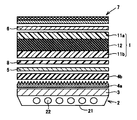
- FIG. 6 shows another embodiment of the liquid crystal display device of the present invention.
- the liquid crystal display device of FIG. 6 is different from the liquid crystal display device of FIG. 4 in that a phase difference plate 8 is disposed between the first polarizing plate 5 and the liquid crystal cell 1.
- This phase difference plate 8 has a substantially zero phase difference in a direction perpendicular to the surface of the liquid crystal cell 1, has no optical effect from the front, and has a phase difference when viewed from an oblique direction. It is intended to compensate for the phase difference that occurs and occurs in the liquid crystal cell 1. As a result, a wider viewing angle can be obtained, and better display quality and color reproducibility can be obtained.
- the phase difference plate 8 can be disposed between the first polarizing plate 5 and the liquid crystal cell 1 and at one or both between the second polarizing plate 6 and the liquid crystal cell 1.
- phase difference plate 8 examples include those obtained by using a polycarbonate resin or a cyclic olefin polymer resin as a film and further biaxially stretching the film, or a liquid crystal monomer having a molecular arrangement fixed by a photopolymerization reaction. Since the phase difference plate 8 optically compensates the alignment of the liquid crystal, the retardation plate 8 having a refractive index characteristic opposite to that of the liquid crystal alignment is used.
- a TN mode liquid crystal display cell for example, “WV film” (manufactured by Fuji Film Co., Ltd.), and for an STN mode liquid crystal display cell, for example, “LC film” (manufactured by Nippon Oil Corporation), IPS
- a biaxial retardation film for a mode liquid crystal cell, and for a VA mode liquid crystal cell for example, a retardation plate combining an A plate and a C-plate, a biaxial retardation film, a ⁇ cell mode liquid crystal cell
- “OCV WV film” manufactured by Fuji Film Co., Ltd.
- Example 1 Production of mirror surface mold Industrial chrome plating is performed on the surface of a 200 mm diameter iron roll (STKM13A by JIS), and then the surface of the mold is mirror polished using this iron roll to produce a mirror mold. did.
- the Vickers hardness of the chromium plating surface of the obtained mold was 1000.
- the Vickers hardness was measured according to JIS Z 2244 using an ultrasonic hardness tester MIC10 (manufactured by Krautkramer) (the measurement method of Vickers hardness is the same in the following examples).
- Pentaerythritol triacrylate 60 parts by mass
- polyfunctional urethanized acrylate reaction product of hexamethylene diisocyanate and pentaerythritol triacrylate, 40 parts by mass
- pentaerythritol triacrylate 40 parts by mass
- the refractive index of the cured product after removing propylene glycol monomethyl ether from the composition and curing with ultraviolet rays was 1.53.
- polystyrene particles having a weight average particle diameter of 12.0 ⁇ m (SBX-12 manufactured by Sekisui Plastics Co., Ltd.) are used as translucent fine particles.
- 30 parts by mass 5 parts by mass of “Lucirin TPO” (manufactured by BASF Corp., chemical name: 2,4,6-trimethylbenzoyldiphenylphosphine oxide) as a photopolymerization initiator is added, and the solid content is 60% by mass.
- a coating solution was prepared by diluting with propylene glycol monomethyl ether.
- This coating solution was coated on a 80 ⁇ m thick triacetyl cellulose (TAC) film (base film) and dried for 1 minute in a dryer set at 80 ° C.
- TAC triacetyl cellulose
- the dried base film was brought into close contact with the mirror surface of the mold produced in (1) above with a rubber roll so that the ultraviolet curable resin composition layer was on the mold side.
- light from a high-pressure mercury lamp with an intensity of 20 mW / cm 2 is irradiated from the base film side so as to be 300 mJ / cm 2 in terms of the amount of h-ray to cure the ultraviolet curable resin composition layer
- Example 2 A light diffusing film was produced in the same manner as in Example 1 except that 35 parts by mass of polystyrene-based particles (SBX-6 manufactured by Sekisui Plastics Co., Ltd.) having a weight average particle size of 6.0 ⁇ m were used as the translucent fine particles. did.
- SBX-6 polystyrene-based particles manufactured by Sekisui Plastics Co., Ltd.
- Comparative Example 1 A light diffusion film was produced in the same manner as in Example 1 except that 10 parts by mass of polystyrene-based particles having a weight average particle size of 6.0 ⁇ m (SBX-6 manufactured by Sekisui Plastics Co., Ltd.) were used as the light-transmitting fine particles. did.
- Comparative Example 2 A light diffusion film was prepared in the same manner as in Example 1 except that 80 parts by mass of polystyrene-based particles having a weight average particle size of 6.0 ⁇ m (SBX-6 manufactured by Sekisui Plastics Co., Ltd.) were used as the light-transmitting fine particles. did.
- Comparative Example 3 Light diffusion in the same manner as in Example 1 except that 40 parts by mass of styrene-methyl methacrylate copolymer particles (manufactured by Sekisui Plastics Co., Ltd.) having a weight average particle size of 6.0 ⁇ m were used as translucent fine particles. A film was prepared.
- Weight average particle diameter of translucent fine particles The weight average particle diameter of the light-transmitting fine particles used in Examples 1 and 2 and Comparative Examples 1 to 3 was measured using a Coulter Multisizer (manufactured by Beckman Coulter, Inc.) based on the Coulter principle (pore electrical resistance method). did.
- the layer thicknesses of the light diffusion films obtained in Examples 1 and 2 and Comparative Examples 1 to 3 were measured using DIGIMICRO MH-15 (main body) and ZC-101 (counter) manufactured by NIKON. The thickness of the light diffusion layer was determined by subtracting the material thickness of 80 ⁇ m.
- the sample In order to prevent the sample from warping, it was bonded to a glass substrate using an optically transparent adhesive so that the second light diffusion layer was on the surface, and the total haze was measured in that state.
- the measurement of the internal haze was performed in the same manner as the measurement of the total haze by sticking a triacetyl cellulose film having a haze of almost 0 to the film surface with glycerin to eliminate the influence of the outside of the film.
- the direction is arranged so that the direction is substantially parallel to the transmission axis of the first polarizing plate, and the other prism film is arranged so that the direction of the ridge line of the linear prism is substantially parallel to the transmission axis of the second polarizing plate.
- the polarizing plate on the light emitting surface side of the liquid crystal cell was peeled off, and an iodine-based normal polarizing plate “TRW842AP7” (manufactured by Sumitomo Chemical Co., Ltd.) was bonded so as to be crossed Nicol. 2 and Comparative Examples 1 to 3 were bonded together to produce a liquid crystal display device.
- the front contrast was measured using the luminance meter "BM5A” type
- the display quality as viewed from the direction in which the viewing angle (angle formed with the front direction of the liquid crystal display device) is 40 °, 50 °, and 60 ° was evaluated.
- Table 2 shows the measurement results of the front contrast
- Table 3 shows the evaluation results of the viewing angles for the liquid crystal display devices using the light diffusion films of Examples 1 and 2 and Comparative Examples 1 to 3.
- Comparative Example 1 since the blending amount of the translucent particles in the light diffusion layer is small, the light diffusion is weak and the front contrast is high, but the viewing angle is narrow. In Comparative Example 2, the amount of translucent particles in the light diffusion layer is too large, so that the light diffusibility is too strong and the viewing angle is wide, but the front contrast is greatly reduced. In Comparative Example 3, since the difference in refractive index between the translucent resin used for the light diffusion layer and the translucent particles is small, the light diffusion is weak and the front contrast is high, but the viewing angle is narrow.
- the liquid crystal display device including the light diffusion film of the present invention has little front scintillation, high front contrast, and wide viewing angle.
Landscapes
- Physics & Mathematics (AREA)
- General Physics & Mathematics (AREA)
- Optics & Photonics (AREA)
- Nonlinear Science (AREA)
- Chemical & Material Sciences (AREA)
- Mathematical Physics (AREA)
- Crystallography & Structural Chemistry (AREA)
- Dispersion Chemistry (AREA)
- Optical Elements Other Than Lenses (AREA)
- Liquid Crystal (AREA)
- Planar Illumination Modules (AREA)
- Laminated Bodies (AREA)
Priority Applications (1)
| Application Number | Priority Date | Filing Date | Title |
|---|---|---|---|
| CN2010800299992A CN102472841A (zh) | 2009-07-08 | 2010-07-05 | 光扩散膜及包含该光扩散膜的液晶显示装置 |
Applications Claiming Priority (2)
| Application Number | Priority Date | Filing Date | Title |
|---|---|---|---|
| JP2009161896 | 2009-07-08 | ||
| JP2009-161896 | 2009-07-08 |
Publications (1)
| Publication Number | Publication Date |
|---|---|
| WO2011004898A1 true WO2011004898A1 (ja) | 2011-01-13 |
Family
ID=43429322
Family Applications (1)
| Application Number | Title | Priority Date | Filing Date |
|---|---|---|---|
| PCT/JP2010/061729 WO2011004898A1 (ja) | 2009-07-08 | 2010-07-05 | 光拡散フィルムおよびそれを含む液晶表示装置 |
Country Status (5)
| Country | Link |
|---|---|
| JP (1) | JP2011034070A (zh) |
| KR (1) | KR20120038445A (zh) |
| CN (1) | CN102472841A (zh) |
| TW (1) | TWI507740B (zh) |
| WO (1) | WO2011004898A1 (zh) |
Cited By (1)
| Publication number | Priority date | Publication date | Assignee | Title |
|---|---|---|---|---|
| CN114114496A (zh) * | 2020-08-31 | 2022-03-01 | 宁波激智科技股份有限公司 | 一种保偏光学膜及其制备方法 |
Families Citing this family (23)
| Publication number | Priority date | Publication date | Assignee | Title |
|---|---|---|---|---|
| CN102483475B (zh) * | 2009-09-04 | 2014-05-21 | 住友化学株式会社 | 光扩散膜及其制造方法、光扩散性偏振板以及液晶显示装置 |
| JP2012212121A (ja) * | 2011-03-18 | 2012-11-01 | Sumitomo Chemical Co Ltd | 偏光子保護フィルム |
| KR101273099B1 (ko) | 2011-05-24 | 2013-06-13 | 엘지이노텍 주식회사 | 광학 시트, 이를 포함하는 표시장치 및 이의 제조방법 |
| JP2013041240A (ja) * | 2011-07-20 | 2013-02-28 | Fujifilm Corp | 液晶表示装置 |
| WO2013080902A1 (ja) * | 2011-12-01 | 2013-06-06 | シャープ株式会社 | 照明装置、照明灯、バックライト、液晶表示装置、およびテレビジョン受信装置 |
| CN102902101B (zh) * | 2012-10-13 | 2015-08-19 | 江苏和成显示科技股份有限公司 | 广视角的液晶显示器 |
| CN103939844A (zh) * | 2013-01-17 | 2014-07-23 | 鸿富锦精密工业(深圳)有限公司 | 扩散片及背光模组 |
| JP6778999B2 (ja) * | 2015-08-12 | 2020-11-04 | 三菱電機株式会社 | 拡散カバー、照明ランプ及び照明装置 |
| JP6753660B2 (ja) * | 2015-10-02 | 2020-09-09 | デクセリアルズ株式会社 | 拡散板、表示装置、投影装置及び照明装置 |
| CN105700263B (zh) | 2016-04-21 | 2019-08-27 | 京东方科技集团股份有限公司 | 一种画质改善膜及其制备方法、显示面板及显示装置 |
| WO2018094645A1 (zh) * | 2016-11-24 | 2018-05-31 | 美的集团股份有限公司 | 空调面板及其制造工艺和空调器 |
| WO2018094651A1 (zh) * | 2016-11-24 | 2018-05-31 | 美的集团股份有限公司 | 空调面板及其制造方法和空调器 |
| CN109946772A (zh) * | 2017-12-21 | 2019-06-28 | 张家港康得新光电材料有限公司 | 一种光扩散层及光扩散片 |
| CN109946773A (zh) * | 2017-12-21 | 2019-06-28 | 张家港康得新光电材料有限公司 | 一种薄型光扩散层及光扩散片 |
| CN109946774A (zh) * | 2017-12-21 | 2019-06-28 | 张家港康得新光电材料有限公司 | 一种薄型高透光的光扩散层及光扩散片 |
| WO2020026891A1 (ja) * | 2018-07-31 | 2020-02-06 | 東洋紡株式会社 | 偏光子保護用ポリエステルフィルム及び液晶表示装置 |
| CN108983336B (zh) * | 2018-08-22 | 2022-12-27 | 张家港康得新光电材料有限公司 | 一种朗伯体扩散片及应用 |
| CN109270611A (zh) * | 2018-12-11 | 2019-01-25 | 宁波激智科技股份有限公司 | 一种高亮度高遮盖的复合光学膜 |
| CN109343268B (zh) * | 2018-12-21 | 2020-06-30 | 深圳市华星光电技术有限公司 | 彩色滤光基板、液晶显示面板及液晶显示装置 |
| US11892665B2 (en) * | 2019-01-23 | 2024-02-06 | Panasonic Intellectual Property Management Co., Ltd. | Colloidal crystal structure, and light-emitting device and lighting system using same |
| CN110236587B (zh) * | 2019-07-11 | 2024-03-01 | 上海联影医疗科技股份有限公司 | 防散射栅格制备方法、探测器装置及医疗影像设备 |
| CN113946070A (zh) * | 2021-09-26 | 2022-01-18 | 深圳市三利谱光电科技股份有限公司 | 一种相位延迟偏光片及其加工工艺和光学显示装置 |
| CN114815372B (zh) * | 2022-05-07 | 2023-10-31 | 深圳市华星光电半导体显示技术有限公司 | 显示面板与显示装置 |
Citations (6)
| Publication number | Priority date | Publication date | Assignee | Title |
|---|---|---|---|---|
| JPH09197109A (ja) * | 1996-01-12 | 1997-07-31 | Kimoto & Co Ltd | 光拡散性シート |
| JPH10506500A (ja) * | 1994-09-27 | 1998-06-23 | ミネソタ マイニング アンド マニュファクチャリング カンパニー | 輝度調節フィルム |
| JP2003114304A (ja) * | 2001-08-02 | 2003-04-18 | Fuji Photo Film Co Ltd | 反射防止フィルム、偏光板、および画像表示装置 |
| JP2006053538A (ja) * | 2004-07-12 | 2006-02-23 | Fuji Photo Film Co Ltd | 反射防止フィルム、偏光板、及びそれを用いた画像表示装置 |
| JP2008040064A (ja) * | 2006-08-04 | 2008-02-21 | Toppan Printing Co Ltd | 防眩性光拡散部材及び防眩性光拡散部材を有するディスプレイ |
| JP2008258141A (ja) * | 2007-03-15 | 2008-10-23 | Sony Corp | 面発光装置、液晶表示装置及び光学シート組合せ体 |
Family Cites Families (4)
| Publication number | Priority date | Publication date | Assignee | Title |
|---|---|---|---|---|
| CN1503009A (zh) * | 2002-11-20 | 2004-06-09 | 力特光电科技股份有限公司 | 抗眩膜 |
| WO2006006254A1 (en) * | 2004-07-12 | 2006-01-19 | Fujifilm Corporation | Antireflection film, polarizing plate, and image display device using the same |
| KR101382369B1 (ko) * | 2006-08-21 | 2014-04-08 | 가부시기가이샤 닛뽕쇼꾸바이 | 미립자, 미립자의 제조방법, 이 미립자를 포함하는 수지 조성물 및 광학 필름 |
| TWM353471U (en) * | 2008-08-15 | 2009-03-21 | Chunghwa Picture Tubes Ltd | Substrate stage |
-
2010
- 2010-07-05 KR KR1020127001270A patent/KR20120038445A/ko not_active Application Discontinuation
- 2010-07-05 CN CN2010800299992A patent/CN102472841A/zh active Pending
- 2010-07-05 JP JP2010152921A patent/JP2011034070A/ja not_active Withdrawn
- 2010-07-05 WO PCT/JP2010/061729 patent/WO2011004898A1/ja active Application Filing
- 2010-07-06 TW TW099122263A patent/TWI507740B/zh active
Patent Citations (6)
| Publication number | Priority date | Publication date | Assignee | Title |
|---|---|---|---|---|
| JPH10506500A (ja) * | 1994-09-27 | 1998-06-23 | ミネソタ マイニング アンド マニュファクチャリング カンパニー | 輝度調節フィルム |
| JPH09197109A (ja) * | 1996-01-12 | 1997-07-31 | Kimoto & Co Ltd | 光拡散性シート |
| JP2003114304A (ja) * | 2001-08-02 | 2003-04-18 | Fuji Photo Film Co Ltd | 反射防止フィルム、偏光板、および画像表示装置 |
| JP2006053538A (ja) * | 2004-07-12 | 2006-02-23 | Fuji Photo Film Co Ltd | 反射防止フィルム、偏光板、及びそれを用いた画像表示装置 |
| JP2008040064A (ja) * | 2006-08-04 | 2008-02-21 | Toppan Printing Co Ltd | 防眩性光拡散部材及び防眩性光拡散部材を有するディスプレイ |
| JP2008258141A (ja) * | 2007-03-15 | 2008-10-23 | Sony Corp | 面発光装置、液晶表示装置及び光学シート組合せ体 |
Cited By (2)
| Publication number | Priority date | Publication date | Assignee | Title |
|---|---|---|---|---|
| CN114114496A (zh) * | 2020-08-31 | 2022-03-01 | 宁波激智科技股份有限公司 | 一种保偏光学膜及其制备方法 |
| CN114114496B (zh) * | 2020-08-31 | 2023-03-21 | 宁波激智科技股份有限公司 | 一种保偏光学膜及其制备方法 |
Also Published As
| Publication number | Publication date |
|---|---|
| CN102472841A (zh) | 2012-05-23 |
| KR20120038445A (ko) | 2012-04-23 |
| TWI507740B (zh) | 2015-11-11 |
| TW201113560A (en) | 2011-04-16 |
| JP2011034070A (ja) | 2011-02-17 |
Similar Documents
| Publication | Publication Date | Title |
|---|---|---|
| WO2011004898A1 (ja) | 光拡散フィルムおよびそれを含む液晶表示装置 | |
| WO2011027903A1 (ja) | 光拡散フィルムおよびその製造方法、光拡散性偏光板、ならびに液晶表示装置 | |
| WO2010073985A1 (ja) | 光学フィルム及びそれを含む液晶表示装置 | |
| WO2011027905A1 (ja) | 光拡散フィルムおよびその製造方法、光拡散性偏光板、ならびに液晶表示装置 | |
| WO2009123114A1 (ja) | 液晶表示装置 | |
| WO2010113873A1 (ja) | 液晶表示装置 | |
| WO2010073997A1 (ja) | 光学フィルム及びそれを含む液晶表示装置 | |
| WO2011162133A1 (ja) | 光拡散性偏光板および液晶表示装置 | |
| WO2011162184A1 (ja) | 光拡散性偏光板および液晶表示装置 | |
| WO2012043410A1 (ja) | 光拡散性偏光板および液晶表示装置 | |
| WO2010113879A1 (ja) | 液晶表示装置 | |
| WO2010018812A1 (ja) | 光路装置及び液晶表示装置 | |
| WO2011162188A1 (ja) | 光拡散性偏光板および液晶表示装置 | |
| JP6058905B2 (ja) | 光拡散フィルムの製造方法及び偏光板の製造方法 | |
| WO2011004906A1 (ja) | 液晶表示装置および光拡散フィルム | |
| JP5827811B2 (ja) | 液晶表示装置 | |
| WO2012074123A1 (ja) | 光学フィルムおよび液晶表示装置 | |
| WO2011162132A1 (ja) | 光拡散性偏光板および液晶表示装置 |
Legal Events
| Date | Code | Title | Description |
|---|---|---|---|
| WWE | Wipo information: entry into national phase |
Ref document number: 201080029999.2 Country of ref document: CN |
|
| 121 | Ep: the epo has been informed by wipo that ep was designated in this application |
Ref document number: 10797209 Country of ref document: EP Kind code of ref document: A1 |
|
| NENP | Non-entry into the national phase |
Ref country code: DE |
|
| ENP | Entry into the national phase |
Ref document number: 20127001270 Country of ref document: KR Kind code of ref document: A |
|
| 122 | Ep: pct application non-entry in european phase |
Ref document number: 10797209 Country of ref document: EP Kind code of ref document: A1 |