WO2011001941A1 - 流路切換バルブ - Google Patents
流路切換バルブ Download PDFInfo
- Publication number
- WO2011001941A1 WO2011001941A1 PCT/JP2010/060986 JP2010060986W WO2011001941A1 WO 2011001941 A1 WO2011001941 A1 WO 2011001941A1 JP 2010060986 W JP2010060986 W JP 2010060986W WO 2011001941 A1 WO2011001941 A1 WO 2011001941A1
- Authority
- WO
- WIPO (PCT)
- Prior art keywords
- rotor
- stator
- flow path
- contact surface
- switching valve
- Prior art date
- Legal status (The legal status is an assumption and is not a legal conclusion. Google has not performed a legal analysis and makes no representation as to the accuracy of the status listed.)
- Ceased
Links
Images





Classifications
-
- F—MECHANICAL ENGINEERING; LIGHTING; HEATING; WEAPONS; BLASTING
- F16—ENGINEERING ELEMENTS AND UNITS; GENERAL MEASURES FOR PRODUCING AND MAINTAINING EFFECTIVE FUNCTIONING OF MACHINES OR INSTALLATIONS; THERMAL INSULATION IN GENERAL
- F16K—VALVES; TAPS; COCKS; ACTUATING-FLOATS; DEVICES FOR VENTING OR AERATING
- F16K11/00—Multiple-way valves, e.g. mixing valves; Pipe fittings incorporating such valves
- F16K11/02—Multiple-way valves, e.g. mixing valves; Pipe fittings incorporating such valves with all movable sealing faces moving as one unit
- F16K11/06—Multiple-way valves, e.g. mixing valves; Pipe fittings incorporating such valves with all movable sealing faces moving as one unit comprising only sliding valves, i.e. sliding closure elements
- F16K11/072—Multiple-way valves, e.g. mixing valves; Pipe fittings incorporating such valves with all movable sealing faces moving as one unit comprising only sliding valves, i.e. sliding closure elements with pivoted closure members
- F16K11/074—Multiple-way valves, e.g. mixing valves; Pipe fittings incorporating such valves with all movable sealing faces moving as one unit comprising only sliding valves, i.e. sliding closure elements with pivoted closure members with flat sealing faces
- F16K11/0743—Multiple-way valves, e.g. mixing valves; Pipe fittings incorporating such valves with all movable sealing faces moving as one unit comprising only sliding valves, i.e. sliding closure elements with pivoted closure members with flat sealing faces with both the supply and the discharge passages being on one side of the closure plates
-
- F—MECHANICAL ENGINEERING; LIGHTING; HEATING; WEAPONS; BLASTING
- F16—ENGINEERING ELEMENTS AND UNITS; GENERAL MEASURES FOR PRODUCING AND MAINTAINING EFFECTIVE FUNCTIONING OF MACHINES OR INSTALLATIONS; THERMAL INSULATION IN GENERAL
- F16K—VALVES; TAPS; COCKS; ACTUATING-FLOATS; DEVICES FOR VENTING OR AERATING
- F16K39/00—Devices for relieving the pressure on the sealing faces
- F16K39/04—Devices for relieving the pressure on the sealing faces for sliding valves
- F16K39/045—Devices for relieving the pressure on the sealing faces for sliding valves of rotating or pivoting type
-
- G—PHYSICS
- G01—MEASURING; TESTING
- G01N—INVESTIGATING OR ANALYSING MATERIALS BY DETERMINING THEIR CHEMICAL OR PHYSICAL PROPERTIES
- G01N30/00—Investigating or analysing materials by separation into components using adsorption, absorption or similar phenomena or using ion-exchange, e.g. chromatography or field flow fractionation
- G01N30/02—Column chromatography
- G01N30/04—Preparation or injection of sample to be analysed
- G01N30/16—Injection
- G01N30/20—Injection using a sampling valve
-
- G—PHYSICS
- G01—MEASURING; TESTING
- G01N—INVESTIGATING OR ANALYSING MATERIALS BY DETERMINING THEIR CHEMICAL OR PHYSICAL PROPERTIES
- G01N30/00—Investigating or analysing materials by separation into components using adsorption, absorption or similar phenomena or using ion-exchange, e.g. chromatography or field flow fractionation
- G01N30/02—Column chromatography
- G01N30/26—Conditioning of the fluid carrier; Flow patterns
- G01N30/28—Control of physical parameters of the fluid carrier
- G01N30/36—Control of physical parameters of the fluid carrier in high pressure liquid systems
-
- G—PHYSICS
- G01—MEASURING; TESTING
- G01N—INVESTIGATING OR ANALYSING MATERIALS BY DETERMINING THEIR CHEMICAL OR PHYSICAL PROPERTIES
- G01N30/00—Investigating or analysing materials by separation into components using adsorption, absorption or similar phenomena or using ion-exchange, e.g. chromatography or field flow fractionation
- G01N30/02—Column chromatography
- G01N30/04—Preparation or injection of sample to be analysed
- G01N30/16—Injection
- G01N30/20—Injection using a sampling valve
- G01N2030/201—Injection using a sampling valve multiport valves, i.e. having more than two ports
-
- G—PHYSICS
- G01—MEASURING; TESTING
- G01N—INVESTIGATING OR ANALYSING MATERIALS BY DETERMINING THEIR CHEMICAL OR PHYSICAL PROPERTIES
- G01N30/00—Investigating or analysing materials by separation into components using adsorption, absorption or similar phenomena or using ion-exchange, e.g. chromatography or field flow fractionation
- G01N30/02—Column chromatography
- G01N30/04—Preparation or injection of sample to be analysed
- G01N30/16—Injection
- G01N30/20—Injection using a sampling valve
- G01N2030/202—Injection using a sampling valve rotary valves
Definitions
- the present invention relates to a flow path switching valve in a sample introduction apparatus for introducing a liquid sample into an analytical instrument, and more particularly to a flow path switching valve for a liquid sample introduced at a high pressure.
- FIG. 1 is a diagram showing an outline of a general flow path of a liquid sample when the liquid sample is analyzed.
- the sample introduction apparatus 30 there are a sample container 31 containing a liquid sample, a cleaning liquid container 32 containing a cleaning liquid, a sampling needle 33, an injection port 34, and the like.
- the liquid in the injection port 34 and the cleaning liquid container 32 flows through the flow path. It is connected to the flow path from the liquid feeding device 20 via the switching valve 1.
- the liquid feeding device 20 sends the mobile phase from the mobile phase container 10 to the sample introduction device 30.
- a large number of liquid samples are sent to the flow path in a predetermined order by the flow path switching valve 1 and are sent to the analysis apparatus 40.
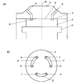
- the switching valve 1 includes a stator 3 having a plurality of ports a to f (only a and d are shown in FIG. 2A) connectable to each flow path, A slidable rotor 2 is provided.
- the rotor 2 is pressed against the stator 3 by a shaft 5 supported by an elastic member (not shown) such as a spring, and the fluid tightness of the flow path is maintained.
- FIG. 2B is a plan view of the contact surface 4 of the rotor 2 with the stator 3, and also shows the openings of the ports a to f of the stator 3.
- the contact surface 4 is provided with arc-shaped channel grooves X, Y, and Z connecting the openings of the ports a to f. These channel grooves X, Y, and Z are connected to the ports a to f. By connecting to f, a flow path is formed. By rotating the rotor 2 around the rotation center 6, the port to which the channel grooves X, Y, Z are connected is changed, and the channel is switched.
- the stator 3 is usually made of metal or ceramic, and the rotor 2 is made of resin.
- an analyzer such as a high-performance liquid chromatograph may send liquid at a higher pressure than before.
- the liquid feeding pressure by the liquid feeding device is high (for example, 50 MPa or more)
- a high-pressure liquid flows from the port connected to the liquid feeding device 20 into the flow path groove of the rotor 2.
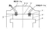
- FIG. 3 is a cross-sectional view of the flow path switching valve 1 that crosses the ports ad during high-pressure liquid feeding.
- FIG. 2 (b) the state where both the openings of the ports a and d are connected to the channel grooves X and Y, respectively, is shown.
- a flow path from the high-pressure liquid feeding device 20 is connected to the port a, and a high-pressure liquid flows into the flow path groove X to which the port a is connected.
- the port to which the channel groove X is not connected is connected to the channel having a substantially atmospheric pressure, only the substantially atmospheric pressure is applied to the openings of the ports cf.
- the rotor 2 Since the rotor 2 is pressed against the stator 3 by a shaft 5 supported by a spring in order to maintain the fluid tightness of the flow path, the rotor 2 is slightly lifted when a high pressure is applied to a part of the rotor 2. Lean on. That is, when high-pressure liquid flows into one port a, the contact surface 4 is opposite to the rotation center 6 of the opening of the high-pressure port a, that is, around the opening of the port d. It is more strongly pressed against the stator 3. When the rotor 2 is rotated while being inclined as described above, there is a problem that the contact surface 4 of the rotor 2 made of a material softer than the stator 3 is damaged and worn.
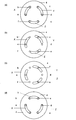
- FIG. 4 is a plan view of the contact surface of the rotor 2 with the stator 3 and shows the switching operation from the communication state of the port ab to the communication state of the port af. .
- FIG. 4A showing the communication state of the port ab
- the port d at the counter electrode of the high-pressure port a communicates with the port c through the channel groove Y
- the port a- showing the communication state of f
- the port d communicates with the port e through the channel groove Z.
- FIG. 4B shows a state immediately after the start of switching from the state of FIG. 4A
- FIG. 4B shows a state immediately after the start of switching from the state of FIG. 4A
- FIG. 4B shows a state immediately after the start of switching from the state of FIG. 4A
- FIG. 4C shows the state where the rotor 2 is further rotated from FIG. The position is shown.
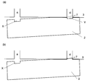
- 5 (a) and 5 (b) are cross-sectional views crossing the ports ad in the states of FIGS. 4 (a) and 4 (b), respectively.
- 6 (a) to 6 (d) are taken along the flow path grooves in the vicinity of the contact surface 4 of the stator 3 and the rotor 2 in the state corresponding to FIGS. 4 (a) to 4 (d), respectively. It is sectional drawing.
- the high-pressure port a is connected to the channel groove X when the port ab is switched to the port af. Therefore, the rotor 2 is pushed downward by the high pressure in the vicinity of the channel groove X. Due to this force, the rotor 2 is slightly tilted (see FIG. 5), and the contact surface 4 of the rotor 2 is strongly pressed against the stator 3 at the counter electrode side portion of the flow channel X, and a load is applied.
- a portion where the load is applied to the contact surface 4 (hereinafter referred to as a load portion) is located at a portion between the ports d and e (see FIG. 6A).
- FIG. 5A shows a cross-sectional view across the port ad at this time.
- the present invention has been made in view of the above problems, and an object thereof is to prevent the contact surface from being scraped off by the edge of the port opening when the rotor is rotated.
- the flow path switching valve according to the first aspect of the present invention made to solve the above problems is a flow path switching valve into which a high pressure liquid and a low pressure liquid flow,
- a rotor having a surface in contact with one surface of the stator and rotating while sliding on the contact surface;
- the stator has a plurality of liquid flow ports that open to the contact surface,
- the rotor is a switching valve having a plurality of channel grooves connecting the liquid circulation ports.
- the channel grooves into which high-pressure liquid flows are configured to be located on both sides of the rotation center of the rotor.
- the flow path switching valve according to the second aspect of the present invention which has been made to solve the above problems,
- a rotor having a surface in contact with one surface of the stator and rotating while sliding on the contact surface;
- the stator has a plurality of liquid flow ports that open to the contact surface,
- the rotor is a switching valve having a flow channel connecting the liquid circulation port,
- the channel groove is configured to be located on both sides of the rotation center of the rotor.
- the flow path switching valve according to the third aspect of the present invention, which has been made to solve the above problems,
- the stator A rotor having a surface in contact with one surface of the stator and rotating while sliding on the contact surface;
- the stator has a plurality of liquid flow ports that open to the contact surface,
- the rotor is a switching valve having a plurality of channel grooves connecting the liquid circulation ports.
- One of the channel grooves is a straight line passing through the rotation center of the rotor, Another channel groove is arranged in line symmetry with the channel groove on the straight line as an axis of symmetry.
- the flow path groove for connecting the high-pressure liquid circulation port is configured to be located on both sides of the rotation center of the rotor.
- FIG. 9 is a plan view of a contact surface of a rotor with a stator, and is an explanatory diagram showing a switching operation from a communication state of a port ab to a communication state of a port af.
- A Cross-sectional view of the contact surface between the rotor and the stator in the communication state of the ports ab, (b) Near the contact surface of the rotor and the stator in the state of switching from the same state FIG. FIG.
- FIG. 10 is a cross-sectional view along the flow path groove in the vicinity of the contact surface between the rotor and the stator, and illustrates the switching operation from the communication state of port ab to the communication state of port af Figure.
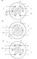
- A A plan view of a contact surface with a rotor of a rotor according to Embodiment 1 of the present invention, (b) a plan view of a contact surface with a rotor of a rotor during channel switching, c) Plan view of the contact surface of the rotor with the stator after the flow path is switched.
- the top view of the contact surface with the stator of the rotor which concerns on the modification 1 of Example 1 of this invention.
- FIG. 7 shows the contact surface 4 with the stator 3 of the rotor 2 of the flow path switching valve 1 having 6 ports according to Embodiment 1 of the present invention.
- the contact surface 4 is provided with three flow channel grooves X1, Y, and Z.
- the openings of ports a to f provided in the stator 3 are also shown.
- the port a is connected to a flow path from the high-pressure liquid feeder 20.
- the flow path groove X1 connected to the high-pressure port a is composed of a straight groove X11 and an arcuate groove X12.
- the groove X11 is a linear groove extending toward the rotation center 6 from the opening of each of the ports a and f to be connected, and the groove X12 is an arc between two grooves X11 extending toward the rotation center. It is the groove
- FIG. 7B shows a state during switching
- FIG. 7C shows a switching completed state.
- the high-pressure liquid flows from the high-pressure port a into the flow path groove X1, and a high-pressure load is applied to the flow path groove X1.
- the channel groove X1 is positioned on both sides of the rotation center
- the portion where the high pressure load is applied on the contact surface 4 of the rotor 2 is on both sides of the rotation center.
- the inclination of the contact surface 4 of the rotor 2 becomes smaller than that of the conventional switching valve. Accordingly, the contact surface 4 can be prevented from being scraped off by the edge of the port opening when the rotor 2 is rotated.
- the flow path groove X2 of the first modification includes an arc-shaped groove X21 and a circular groove X23, and a linear groove X22 connecting the two.
- the groove X21 is a groove formed by connecting the port openings in an arc shape at the shortest distance, as in the conventional flow path switching valve.
- the groove X23 is a circular groove having the rotation center 6 as the center, and the groove X22 has a shape connecting the center portion of the groove X21 and the groove X23. Also in this modified example 1, since the flow channel X2 is located on both sides of the rotation center 6, the inclination of the rotor 2 can be made gentle even during high pressure liquid feeding.
- the first modification is easier to process the channel grooves than the first embodiment and other modifications described later.
- the flow path groove X3 is a U-shaped groove that connects the port openings to be connected to each other via the opposite side of the rotation center 6. Since the channel groove X3 is also composed of the linear groove X31 and the arc-shaped groove X32, it is similar to the shape of the channel groove X1 of the first embodiment. However, in the first embodiment, since the linear groove X11 extends toward the center of rotation, it is necessary to lengthen the portion where the arc-shaped groove X12 extends in the rotation direction. Therefore, the flow path groove X3 of the modified example 2 is somewhat easier to process the flow path groove than the first embodiment. In the second modification as well, the inclination of the rotor 2 can be made gentle even during high pressure liquid feeding.
- the flow path groove X4 also includes two linear grooves X41 and an arc-shaped groove X42.
- the groove X41 extends from the opening of the port toward the outer periphery of the contact surface.
- the groove X42 is composed of a dominant arc connecting the outer peripheral ends of the two grooves X41, and is located on the outer peripheral side of the flow path grooves Y and Z. Since the flow path groove X4 of the third modification is provided on the contact surface 4 in the widest range of the first embodiment and the modification of the present invention, it is very effective in terms of pressure dispersion.
- the inclination of the contact surface 4 of the rotor 2 can be made most gradual as compared with the first embodiment and other modified examples.
- the arc-shaped groove is formed on the outer periphery of the other flow channel grooves Y and Z, if there is not enough space on the outer periphery of the other flow channel grooves X and Y in the contact surface 4, processing is difficult. Further, there is a possibility that the strength of the contact surface 4 is lowered by forming the flow channel groove X4 over a wide range on the contact surface 4. Since the contact surface 4 is provided in a wide range, it is very effective in terms of pressure dispersion. For this reason, the inclination of the contact surface 4 of the rotor 2 can be made most gradual as compared with the first embodiment and other modified examples.
- FIG. 11 shows a fourth modification of the flow path switching valve in which only one flow path groove is provided on the contact surface 4.
- the channel groove X5 has a shape similar to the channel groove X1 of the first embodiment shown in FIG.
- the solid line shows the state where the high-pressure port a is connected to the port c through the flow channel X5, and the dotted line shows the high-pressure port a connected to the port b by rotating the rotor 2. Indicates the state. Even in the flow path switching valve according to this modification, the local load applied to the rotor during high-pressure liquid feeding is reduced.
- the channel grooves connected to the high pressure port are all located on both sides of the rotation center 6, the inclination of the rotor 2 during high pressure liquid feeding can be made gentle. . Therefore, the contact surface 4 can be prevented from being scraped off by the edge 7 of the port opening when the rotor 2 rotates.
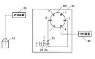
- FIG. 12 is a flow path configuration diagram using the flow path switching valve 101 according to the second embodiment of the present invention.
- the flow path switching valve 101 uses a valve that rotates and slides a disk-shaped rotor having flow path grooves P, Q1, and Q2 shown in FIG. 13 with respect to a disk-shaped stator having six ports g to l. It is done.
- the liquid feeding device 20 and the analysis device 40 are connected to the opposed ports h and k, and the sampling needle 33 is connected to the port g adjacent to the port h to which the liquid feeding device 20 is connected.
- the injection port 34 is connected to the port j facing the port g.
- the contact surface 104 of the rotor and stator is as shown in FIG. 13, but the assembly of the rotor and stator is the same as in FIG.
- the channel groove P on the rotor connects two opposing ports with a straight line passing through the rotation center 6 of the rotor.
- the other channel grooves Q1 and Q2 each connect adjacent ports in an arc shape, and these are arranged line-symmetrically with the channel groove P as an axis of symmetry.
- FIG. 13 is an explanatory diagram of channel switching using the channel switching valve 101 according to this embodiment.
- FIG. 13A shows the flow channel configuration during loading of the sample in the sample container 31
- FIG. 13C shows the flow channel configuration during sample injection
- FIGS. 13B and 13D show the contact surface 104 during switching. ing.
- a flow path under a high pressure load is indicated by a bold line.
- the high-pressure port h to which the liquid delivery device 20 is connected is open to the linear flow channel P, and the high-pressure mobile phase is passed through the flow channel P. Is flowing in.
- Ports g and j to which the sampling needle 33 and the injection port 34 are connected open to the arc-shaped flow channel grooves Q1 and Q2, and are sucked from the sampling needle 33 and passed through the injection port 34 in the sample container 31.
- the sample is loaded into a sample loop (not shown).
- FIG. 13B shows the state of the flow path switching valve 101 during switching.
- a high pressure load is applied to the flow channel P immediately before switching the flow channel.
- the flow channel P is a straight line passing through the rotation center 6, a portion where a high pressure load is applied on the contact surface 104 of the rotor.
- the contact surface 104 can be prevented from being scraped off by the edge of the port opening.
- the sample loaded in the sample loop in the loading state (a) is injected into the analysis device 40 on the mobile phase fed from the liquid feeding device 20.
- the high-pressure port h to which the liquid feeding device 20 is connected opens in the arc-shaped channel groove Q1, and the high-pressure mobile phase flows from the channel groove Q1 through the injection port 34 into the channel groove Q2. That is, in the injection state (c), a high pressure load is applied to the flow channel grooves Q1 and Q2.
- the flow path grooves Q1 and Q2 to which a high-pressure load is applied are evenly distributed on both sides around the rotation axis. Sometimes, the contact surface 104 can be prevented from being scraped off.
- this invention is not limited to said Example and modification, A suitable structure is accept
- the flow path switching valve of the above embodiment has 6 ports, it is naturally possible to increase the number of ports.
Landscapes
- Engineering & Computer Science (AREA)
- General Engineering & Computer Science (AREA)
- Mechanical Engineering (AREA)
- Physics & Mathematics (AREA)
- Health & Medical Sciences (AREA)
- Life Sciences & Earth Sciences (AREA)
- Chemical & Material Sciences (AREA)
- Analytical Chemistry (AREA)
- Biochemistry (AREA)
- General Health & Medical Sciences (AREA)
- General Physics & Mathematics (AREA)
- Immunology (AREA)
- Pathology (AREA)
- Multiple-Way Valves (AREA)
Abstract
Description
図4はロ-タ2のステ-タ3との接触面の平面図であり、ポ-トa-bの連通状態からポ-トa-fの連通状態への切り換え動作を示すものである。ポ-トa-bの連通状態を示す図4(a)では、高圧ポ-トaの対極にあるポ-トdが流路溝Yによってポ-トcと連通し、ポ-トa-fの連通状態を示す図4(d)では、ポ-トdが流路溝Zによってポ-トeと連通している。図4(b)は(a)の状態から切り換え始めた直後の状態、(c)は(b)から更にロ-タ2を回転させ、ポ-トdが流路溝YとZの中間に位置する状態を示している。図5(a)、(b)はそれぞれ、図4(a)、(b)の状態におけるポ-トa-dを横断する断面図である。また、図6(a)~(d)はそれぞれ、図4(a)~(d)に対応する状態にあるステ-タ3とロ-タ2の接触面4付近における流路溝に沿った断面図である。
エッジ7によって負荷部分が削り取られる現象は流路の切り換え動作毎に起こるため、流路切換を繰り返すうちにロ-タ2の接触面4が部分的に摩耗、損傷する。損傷の場所によっては流路溝が延長され、本来とは異なるタイミングで流路切換が生じることもある。さらには、隣の流路溝同士が連結するという問題も生じる。
ステ-タと、
このステ-タの一面と接触する面を有し、この接触面で摺動しつつ回転するロ-タとを備え、
前記ステ-タは前記接触面に開口する複数の液体流通ポ-トを有し、
前記ロ-タは前記液体流通ポ-トを連結する複数の流路溝を有する切換バルブにおいて、
前記流路溝のうち高圧の液体が流入する流路溝は、ロ-タの回転中心を挟んで両側に位置するように構成されていることを特徴とする。
ステ-タと、
このステ-タの一面と接触する面を有し、この接触面で摺動しつつ回転するロ-タとを備え、
前記ステ-タは前記接触面に開口する複数の液体流通ポ-トを有し、
前記ロ-タは前記液体流通ポ-トを連結する流路溝を有する切換バルブにおいて、
前記流路溝は、ロ-タの回転中心を挟んで両側に位置するように構成されていることを特徴とする。
ステ-タと、
このステ-タの一面と接触する面を有し、この接触面で摺動しつつ回転するロ-タとを備え、
前記ステ-タは前記接触面に開口する複数の液体流通ポ-トを有し、
前記ロ-タは前記液体流通ポ-トを連結する複数の流路溝を有する切換バルブにおいて、
前記流路溝の一つは、前記ロータの回転中心を通る直線状であり、
前記直線上の流路溝を対称軸として線対称に他の流路溝が配置されていることを特徴とする。
この変形例1は実施例1や後述する他の変形例と比べ、流路溝の加工が容易である。
本変形例3の流路溝X4は、本発明の実施例1、変形例の中で一番広範囲に接触面4に設けられるため、圧力の分散化の面で非常に有効である。このため、実施例1や他の変形例に比べると、ロ-タ2の接触面4の傾斜をもっとも緩やかにできる。ただし、他の流路溝Y、Zの外周に円弧状の溝を形成するため、接触面4のうち他の流路溝X、Yの外周に十分なスペースがない場合には加工が難しく、また、接触面4に広範囲にわたる流路溝X4を形成することにより接触面4の強度が低下する可能性があるが、流路溝X4は、本発明の実施例1、変形例の中で最も広範囲に接触面4に設けられるため、圧力の分散化の面で非常に有効である。このため、実施例1や他の変形例に比べると、ロ-タ2の接触面4の傾斜をもっとも緩やかにできる。
図13(a)のロード状態では、送液装置20の接続された高圧ポートhは直線状の流路溝Pに開口しており、高圧の移動相が流路溝Pを介して分析装置40に流入している。サンプリングニードル33と注入ポート34の接続されたポートg、jは円弧状の流路溝Q1、Q2に開口しており、サンプリングニードル33から吸引され、注入ポート34を介して、試料容器31中の試料がサンプルループ(図示なし)中にロードされる。
2…ロ-タ
3…ステ-タ
4、104…ロ-タとステ-タの接触面
5…シャフト
6…ロ-タ回転中心
7…高圧ポ-ト開口部のエッジ
10…移動相容器
20…送液装置
30…試料導入装置
31…試料容器
32…洗浄容器
33…サンプリングニードル
34…注入ポート
40…分析装置
a~f、g~l…ポ-ト
X~Z、P、Q1、Q2…流路溝
Claims (3)
- ステ-タと、
このステ-タの一面と接触する面を有し、この接触面で摺動しつつ回転するロ-タとを備え、
前記ステ-タは前記接触面に開口する複数の液体流通ポ-トを有し、
前記ロ-タは前記液体流通ポ-トを連結する複数の流路溝を有する切換バルブにおいて、
前記流路溝の一つは、前記ロータの回転中心を通る直線状であり、
前記直線上の流路溝を対称軸として線対称に他の流路溝が配置されていることを特徴とする流路切換バルブ。 - ステ-タと、
このステ-タの一面と接触する面を有し、この接触面で摺動しつつ回転するロ-タとを備え、
前記ステ-タは前記接触面に開口する複数の液体流通ポ-トを有し、
前記ロ-タは前記液体流通ポ-トを連結する流路溝を有する切換バルブにおいて、
前記流路溝は、ロ-タの回転中心を挟んで両側に位置するように構成されていることを特徴とする流路切換バルブ。 - 高圧の液体と低圧の液体が流入する流路切換バルブであって、
ステ-タと、
このステ-タの一面と接触する面を有し、この接触面で摺動しつつ回転するロ-タとを備え、
前記ステ-タは前記接触面に開口する複数の液体流通ポ-トを有し、
前記ロ-タは前記液体流通ポ-トを連結する複数の流路溝を有する切換バルブにおいて、
前記流路溝のうち高圧の液体が流入する流路溝は、ロ-タの回転中心を挟んで両側に位置するように構成されていることを特徴とする流路切換バルブ。
Priority Applications (4)
| Application Number | Priority Date | Filing Date | Title |
|---|---|---|---|
| US13/379,603 US8236175B2 (en) | 2009-06-29 | 2010-06-28 | Liquid chromatograph system |
| CN2010800291632A CN102472400B (zh) | 2009-06-29 | 2010-06-28 | 液相色谱仪系统 |
| JP2011520913A JP5573838B2 (ja) | 2009-06-29 | 2010-06-28 | 液体クロマトグラフ装置 |
| US13/541,193 US8382979B2 (en) | 2009-06-29 | 2012-07-03 | Liquid chromatograph system |
Applications Claiming Priority (2)
| Application Number | Priority Date | Filing Date | Title |
|---|---|---|---|
| PCT/JP2009/002990 WO2011001460A1 (ja) | 2009-06-29 | 2009-06-29 | 流路切換バルブ |
| JPPCT/JP2009/002990 | 2009-06-29 |
Related Child Applications (2)
| Application Number | Title | Priority Date | Filing Date |
|---|---|---|---|
| US13/379,603 A-371-Of-International US8236175B2 (en) | 2009-06-29 | 2010-06-28 | Liquid chromatograph system |
| US13/541,193 Division US8382979B2 (en) | 2009-06-29 | 2012-07-03 | Liquid chromatograph system |
Publications (1)
| Publication Number | Publication Date |
|---|---|
| WO2011001941A1 true WO2011001941A1 (ja) | 2011-01-06 |
Family
ID=43410564
Family Applications (2)
| Application Number | Title | Priority Date | Filing Date |
|---|---|---|---|
| PCT/JP2009/002990 Ceased WO2011001460A1 (ja) | 2009-06-29 | 2009-06-29 | 流路切換バルブ |
| PCT/JP2010/060986 Ceased WO2011001941A1 (ja) | 2009-06-29 | 2010-06-28 | 流路切換バルブ |
Family Applications Before (1)
| Application Number | Title | Priority Date | Filing Date |
|---|---|---|---|
| PCT/JP2009/002990 Ceased WO2011001460A1 (ja) | 2009-06-29 | 2009-06-29 | 流路切換バルブ |
Country Status (3)
| Country | Link |
|---|---|
| US (2) | US8236175B2 (ja) |
| CN (1) | CN102472400B (ja) |
| WO (2) | WO2011001460A1 (ja) |
Cited By (2)
| Publication number | Priority date | Publication date | Assignee | Title |
|---|---|---|---|---|
| JP2011185850A (ja) * | 2010-03-10 | 2011-09-22 | Ckd Corp | サンプルインジェクタ |
| WO2013069401A1 (ja) * | 2011-11-11 | 2013-05-16 | 株式会社島津製作所 | 流路切換バルブ |
Families Citing this family (24)
| Publication number | Priority date | Publication date | Assignee | Title |
|---|---|---|---|---|
| US8881582B2 (en) * | 2005-01-31 | 2014-11-11 | Waters Technologies Corporation | Method and apparatus for sample injection in liquid chromatography |
| US20130112604A1 (en) * | 2010-06-16 | 2013-05-09 | Waters Technologies Corporation | Valve For High Pressure Analytical System |
| US9939415B2 (en) | 2011-01-12 | 2018-04-10 | Dionex Softron Gmbh | High-pressure control valve for high-performance liquid chromatography |
| DE102011000104B4 (de) * | 2011-01-12 | 2013-02-07 | Dionex Softron Gmbh | Hochdruck-Schaltventil für die Hochleistungsflüssigkeitschromatographie |
| US8813785B2 (en) * | 2012-01-09 | 2014-08-26 | Promochrom Technologies Ltd. | Fluid selection valve |
| US9625044B2 (en) | 2012-08-22 | 2017-04-18 | Ge Healthcare Bio-Sciences Ab | Versatile rotary valve |
| CN102928555A (zh) * | 2012-09-29 | 2013-02-13 | 聚光科技(杭州)股份有限公司 | 一种烟气复合分析系统及方法 |
| CN102996855A (zh) * | 2012-10-23 | 2013-03-27 | 苏州宇东暖通技术有限公司 | 液压助力阀三通开关陶瓷控制装置 |
| JP5999252B2 (ja) * | 2013-03-11 | 2016-09-28 | 株式会社島津製作所 | 流路切換バルブ |
| JP6575946B2 (ja) * | 2013-12-19 | 2019-09-18 | ジーイー・ヘルスケア・バイオサイエンス・アクチボラグ | 回転弁及びクロマトグラフィシステム |
| JP6612242B2 (ja) * | 2014-02-14 | 2019-11-27 | ジーイー・ヘルスケア・バイオサイエンス・アクチボラグ | 自動化された多段階精製システム及び多段階クロマトグラフィー精製方法 |
| US9739383B2 (en) * | 2014-07-29 | 2017-08-22 | Idex Health & Science Llc | Multi-path selector valve |
| CN104633182A (zh) * | 2015-02-16 | 2015-05-20 | 苏州赛谱仪器有限公司 | 柱位阀 |
| DE102016101658B4 (de) | 2016-01-29 | 2018-04-05 | Dionex Softron Gmbh | Probenvorkompressionsventil für die Flüssigkeitschromatographie, insbesondere für die Hochleistungsflüssigkeitschromatographie |
| DE102017101629A1 (de) | 2017-01-27 | 2018-08-02 | Agilent Technologies, Inc. - A Delaware Corporation - | Fluidventil mit goldhaltiger und/oder platinhaltiger Beschichtung |
| US11812525B2 (en) | 2017-06-27 | 2023-11-07 | Wangs Alliance Corporation | Methods and apparatus for controlling the current supplied to light emitting diodes |
| US11214479B2 (en) | 2017-11-10 | 2022-01-04 | Pentair Flow Technologies, Llc | Probe assembly for use in a closed transfer system |
| US11119076B2 (en) * | 2018-02-26 | 2021-09-14 | Valco Instruments Company, L.P. | System and valve for liquid chromatography |
| CN108397571B (zh) * | 2018-02-28 | 2021-08-06 | 深圳市罗伯医疗科技有限公司 | 旋转式换向阀 |
| JP6922837B2 (ja) * | 2018-05-16 | 2021-08-18 | 株式会社デンソー | 電磁弁 |
| JP7144611B2 (ja) * | 2018-11-01 | 2022-09-29 | アイデックス ヘルス アンド サイエンス エルエルシー | 複数チャネル・セレクター・バルブ |
| JP7133499B2 (ja) | 2019-03-07 | 2022-09-08 | 株式会社日立ハイテク | 流路切替バルブ及びそれを有する液体クロマトグラフ |
| JP7303723B2 (ja) * | 2019-10-17 | 2023-07-05 | 株式会社日立ハイテク | 流路切替バルブシステムおよび液体クロマトグラフ |
| US12320441B1 (en) * | 2021-02-08 | 2025-06-03 | Schivo Medical Limited | Centering electronic rotary valve |
Citations (5)
| Publication number | Priority date | Publication date | Assignee | Title |
|---|---|---|---|---|
| JPS4939833A (ja) * | 1972-08-26 | 1974-04-13 | ||
| JPS60149973A (ja) * | 1984-01-17 | 1985-08-07 | Toyo Soda Mfg Co Ltd | 液注入装置 |
| JPS61233363A (ja) * | 1984-09-12 | 1986-10-17 | Toyo Soda Mfg Co Ltd | 液注入装置 |
| JPH04204156A (ja) * | 1990-11-30 | 1992-07-24 | Yokogawa Electric Corp | 試料注入装置 |
| JP2008215494A (ja) * | 2007-03-05 | 2008-09-18 | Shimadzu Corp | 流路切換えバルブ |
Family Cites Families (14)
| Publication number | Priority date | Publication date | Assignee | Title |
|---|---|---|---|---|
| US4625569A (en) * | 1984-01-17 | 1986-12-02 | Toyo Soda Manufacturing Co., Ltd. | Liquid injection device |
| JPS6123363A (ja) | 1984-07-11 | 1986-01-31 | Toshiba Corp | 半導体装置およびその製造方法 |
| JPH0939833A (ja) * | 1995-07-26 | 1997-02-10 | Honda Motor Co Ltd | 自動車のフロントピラー |
| DE19926163B4 (de) * | 1998-06-19 | 2008-07-03 | Shimadzu Corp. | Flüssigchromatograph |
| FR2794836B1 (fr) * | 1999-06-09 | 2001-08-03 | Inst Francais Du Petrole | Vanne rotative amelioree |
| JP3823092B2 (ja) * | 2003-03-11 | 2006-09-20 | 株式会社日立ハイテクノロジーズ | 分離分析装置 |
| EP1789708B1 (en) * | 2004-08-25 | 2011-10-19 | Mécanique Analytique Inc. | Rotary valve and analytical chromatographic system using the same |
| JP4670590B2 (ja) * | 2005-10-28 | 2011-04-13 | 株式会社島津製作所 | 流路切換バルブ及びそれを用いた高速液体クロマトグラフ |
| JP4913470B2 (ja) * | 2006-04-26 | 2012-04-11 | 株式会社島津製作所 | 流路切換えバルブを用いた高速液体クロマトグラフ及び分析方法 |
| JP5377477B2 (ja) * | 2007-05-15 | 2013-12-25 | ジーイー・ヘルスケア・バイオ−サイエンシズ・アーベー | 流れ分配弁 |
| US8567441B2 (en) | 2007-09-28 | 2013-10-29 | Shimadzu Corporation | Sample introduction device |
| DE102007059651B4 (de) * | 2007-12-10 | 2017-05-24 | Dionex Softron Gmbh | Probengeber für die Hochleistungsflüssigkeitschromatographie |
| US9316324B2 (en) * | 2008-10-29 | 2016-04-19 | Agilent Technologies, Inc. | Shear valve with silicon carbide member |
| WO2010083147A1 (en) * | 2009-01-14 | 2010-07-22 | Waters Technologies Corporation | Rotating valve |
-
2009
- 2009-06-29 WO PCT/JP2009/002990 patent/WO2011001460A1/ja not_active Ceased
-
2010
- 2010-06-28 CN CN2010800291632A patent/CN102472400B/zh active Active
- 2010-06-28 US US13/379,603 patent/US8236175B2/en active Active
- 2010-06-28 WO PCT/JP2010/060986 patent/WO2011001941A1/ja not_active Ceased
-
2012
- 2012-07-03 US US13/541,193 patent/US8382979B2/en active Active
Patent Citations (5)
| Publication number | Priority date | Publication date | Assignee | Title |
|---|---|---|---|---|
| JPS4939833A (ja) * | 1972-08-26 | 1974-04-13 | ||
| JPS60149973A (ja) * | 1984-01-17 | 1985-08-07 | Toyo Soda Mfg Co Ltd | 液注入装置 |
| JPS61233363A (ja) * | 1984-09-12 | 1986-10-17 | Toyo Soda Mfg Co Ltd | 液注入装置 |
| JPH04204156A (ja) * | 1990-11-30 | 1992-07-24 | Yokogawa Electric Corp | 試料注入装置 |
| JP2008215494A (ja) * | 2007-03-05 | 2008-09-18 | Shimadzu Corp | 流路切換えバルブ |
Cited By (3)
| Publication number | Priority date | Publication date | Assignee | Title |
|---|---|---|---|---|
| JP2011185850A (ja) * | 2010-03-10 | 2011-09-22 | Ckd Corp | サンプルインジェクタ |
| WO2013069401A1 (ja) * | 2011-11-11 | 2013-05-16 | 株式会社島津製作所 | 流路切換バルブ |
| US9200715B2 (en) | 2011-11-11 | 2015-12-01 | Shimadzu Corporation | Passage-switching valve |
Also Published As
| Publication number | Publication date |
|---|---|
| CN102472400A (zh) | 2012-05-23 |
| CN102472400B (zh) | 2013-11-13 |
| US20120103887A1 (en) | 2012-05-03 |
| WO2011001460A1 (ja) | 2011-01-06 |
| US8236175B2 (en) | 2012-08-07 |
| US8382979B2 (en) | 2013-02-26 |
| US20130000390A1 (en) | 2013-01-03 |
Similar Documents
| Publication | Publication Date | Title |
|---|---|---|
| WO2011001941A1 (ja) | 流路切換バルブ | |
| US10113995B2 (en) | Multi-position, micro-fluidic valve assembly with multiple radial grooves to enable individual or combined flows | |
| EP2196801B1 (en) | Method and apparatus for injecting a liquid sample in an HPLC analyzing device, and valve assembly for use therein. | |
| CN103314289B (zh) | 用于高效液相色谱分析法的高压控制阀 | |
| US8656955B2 (en) | Rotary column selector valve | |
| US9679757B2 (en) | Liquid chromatography systems and methods | |
| US20160377184A1 (en) | Fluid Switching Valve and Liquid Chromatograph Apparatus Using the Same | |
| CN107121519A (zh) | 一种内置流通通道结构的切换阀 | |
| JP5573838B2 (ja) | 液体クロマトグラフ装置 | |
| JP7133499B2 (ja) | 流路切替バルブ及びそれを有する液体クロマトグラフ | |
| KR100757512B1 (ko) | 초고압 이중 온라인 고체상 추출 및 역상 액체크로마토그래피 장치 | |
| CN104024847A (zh) | 流路切换阀 | |
| KR20150088867A (ko) | 스퍼터링 장치 및 기판 처리 장치 | |
| WO2013069401A1 (ja) | 流路切換バルブ | |
| US10914394B2 (en) | Fluidic valve with contactless force transmission for pressing together stator and rotor | |
| JP6019516B2 (ja) | 基板処理装置 | |
| Svejdal et al. | Thiol-ene microfluidic chip for fast on-chip sample clean-up, separation and ESI mass spectrometry of peptides and proteins | |
| US20220326197A1 (en) | Flow passage switching valve, flow passage switching valve system, and liquid chromatograph | |
| JP6562508B2 (ja) | 基板保持装置 | |
| CN102052489A (zh) | 具有带倾斜外表面的球形座的用于高效液相色谱仪的阀 | |
| US20220128521A1 (en) | Autosampler for chromatograph | |
| CN108398514A (zh) | 一种测定肽分子量的一体式阀切换二维液相色谱及其应用 | |
| US20100212595A1 (en) | Support Assembly For Substrate Holder, As Well As A Device Provided With Such A Support Assembly For Layered Deposition Of Various Semiconductor Materials On A Semiconductor Substrate | |
| JP7474691B2 (ja) | 流路切替バルブおよび液体クロマトグラフ | |
| JPH11315942A (ja) | スライド式切換弁 |
Legal Events
| Date | Code | Title | Description |
|---|---|---|---|
| WWE | Wipo information: entry into national phase |
Ref document number: 201080029163.2 Country of ref document: CN |
|
| 121 | Ep: the epo has been informed by wipo that ep was designated in this application |
Ref document number: 10794110 Country of ref document: EP Kind code of ref document: A1 |
|
| WWE | Wipo information: entry into national phase |
Ref document number: 2011520913 Country of ref document: JP |
|
| WWE | Wipo information: entry into national phase |
Ref document number: 13379603 Country of ref document: US |
|
| WWE | Wipo information: entry into national phase |
Ref document number: 9871/CHENP/2011 Country of ref document: IN |
|
| NENP | Non-entry into the national phase |
Ref country code: DE |
|
| 122 | Ep: pct application non-entry in european phase |
Ref document number: 10794110 Country of ref document: EP Kind code of ref document: A1 |