WO2011001505A1 - 現金自動取引装置 - Google Patents
現金自動取引装置 Download PDFInfo
- Publication number
- WO2011001505A1 WO2011001505A1 PCT/JP2009/061933 JP2009061933W WO2011001505A1 WO 2011001505 A1 WO2011001505 A1 WO 2011001505A1 JP 2009061933 W JP2009061933 W JP 2009061933W WO 2011001505 A1 WO2011001505 A1 WO 2011001505A1
- Authority
- WO
- WIPO (PCT)
- Prior art keywords
- shutter
- unit
- opening
- fixed shaft
- shutter member
- Prior art date
- Legal status (The legal status is an assumption and is not a legal conclusion. Google has not performed a legal analysis and makes no representation as to the accuracy of the status listed.)
- Ceased
Links
Images




Classifications
-
- G—PHYSICS
- G07—CHECKING-DEVICES
- G07F—COIN-FREED OR LIKE APPARATUS
- G07F19/00—Complete banking systems; Coded card-freed arrangements adapted for dispensing or receiving monies or the like and posting such transactions to existing accounts, e.g. automatic teller machines
-
- G—PHYSICS
- G07—CHECKING-DEVICES
- G07F—COIN-FREED OR LIKE APPARATUS
- G07F19/00—Complete banking systems; Coded card-freed arrangements adapted for dispensing or receiving monies or the like and posting such transactions to existing accounts, e.g. automatic teller machines
- G07F19/20—Automatic teller machines [ATMs]
- G07F19/205—Housing aspects of ATMs
-
- B—PERFORMING OPERATIONS; TRANSPORTING
- B65—CONVEYING; PACKING; STORING; HANDLING THIN OR FILAMENTARY MATERIAL
- B65H—HANDLING THIN OR FILAMENTARY MATERIAL, e.g. SHEETS, WEBS, CABLES
- B65H1/00—Supports or magazines for piles from which articles are to be separated
- B65H1/26—Supports or magazines for piles from which articles are to be separated with auxiliary supports to facilitate introduction or renewal of the pile
-
- G—PHYSICS
- G07—CHECKING-DEVICES
- G07D—HANDLING OF COINS OR VALUABLE PAPERS, e.g. TESTING, SORTING BY DENOMINATIONS, COUNTING, DISPENSING, CHANGING OR DEPOSITING
- G07D11/00—Devices accepting coins; Devices accepting, dispensing, sorting or counting valuable papers
- G07D11/10—Mechanical details
- G07D11/14—Inlet or outlet ports
-
- G—PHYSICS
- G07—CHECKING-DEVICES
- G07F—COIN-FREED OR LIKE APPARATUS
- G07F19/00—Complete banking systems; Coded card-freed arrangements adapted for dispensing or receiving monies or the like and posting such transactions to existing accounts, e.g. automatic teller machines
- G07F19/20—Automatic teller machines [ATMs]
-
- B—PERFORMING OPERATIONS; TRANSPORTING
- B65—CONVEYING; PACKING; STORING; HANDLING THIN OR FILAMENTARY MATERIAL
- B65H—HANDLING THIN OR FILAMENTARY MATERIAL, e.g. SHEETS, WEBS, CABLES
- B65H2402/00—Constructional details of the handling apparatus
- B65H2402/40—Details of frames, housings or mountings of the whole handling apparatus
- B65H2402/45—Doors
-
- B—PERFORMING OPERATIONS; TRANSPORTING
- B65—CONVEYING; PACKING; STORING; HANDLING THIN OR FILAMENTARY MATERIAL
- B65H—HANDLING THIN OR FILAMENTARY MATERIAL, e.g. SHEETS, WEBS, CABLES
- B65H2407/00—Means not provided for in groups B65H2220/00 – B65H2406/00 specially adapted for particular purposes
- B65H2407/10—Safety means, e.g. for preventing injuries or illegal operations
-
- B—PERFORMING OPERATIONS; TRANSPORTING
- B65—CONVEYING; PACKING; STORING; HANDLING THIN OR FILAMENTARY MATERIAL
- B65H—HANDLING THIN OR FILAMENTARY MATERIAL, e.g. SHEETS, WEBS, CABLES
- B65H2407/00—Means not provided for in groups B65H2220/00 – B65H2406/00 specially adapted for particular purposes
- B65H2407/30—Means for preventing damage of handled material, e.g. by controlling atmosphere
Definitions
- the present invention relates to an automatic teller machine, and in particular, includes a shutter that closes an opening on the customer service side that opens when a unit that is retractably stored in the case is pulled out to the back side of the case. It relates to an automatic teller machine.
- An automatic teller machine such as an automated teller machine installed in a financial institution has a plurality of openings in the front panel on the customer service side of the case, and the inside of the case corresponding to each opening.
- Some of these units are installed on the back side of the casing so that they can be pulled out in preparation for maintenance work such as repair, parts replacement, cash storage / collection, and replenishment of statement slip sheets.
- the shutter mechanism described in Patent Document 1 includes a shutter that can be moved up and down, an arm that has one end pivotally provided on an arm base, and the other end that is engaged with a roller provided on the shutter; And a spring that urges the arm in the direction of lifting to lift the shutter to the position of the opening.
- the projection provided on the unit pushes down the arm in conjunction with the storing operation of the unit, and the shutter is retracted from the opening by its own weight.
- the arm is rotated by the biasing force of the spring, lifts the shutter to the position of the opening, and closes the opening.
- the shutter lock mechanism includes a stopper bracket that is rotatably attached to the arm base in the horizontal direction, and a stopper spring that rotates the stopper bracket.
- the stopper bracket When the unit is pulled out to the back side of the automatic teller machine, the stopper bracket is rotated by the stopper spring, and the stopper pin provided at the tip is engaged with the engagement hole of the arm that has pushed up the shutter. As a result, the arm is locked, so that the shutter cannot be opened even if the shutter is subjected to a pressing force in the direction of opening through the opening.
- Patent Document 1 since the device described in Patent Document 1 includes a mechanism for opening and closing the shutter and a mechanism for locking the shutter, the number of parts constituting the mechanism is large, and the manufacturing cost is high. There is a problem that a large installation space is required to accommodate many parts.
- the present invention has been made in view of such a point, and an object thereof is to provide an automatic teller machine capable of realizing a shutter with locking at a low cost with a simple configuration.
- an operation port is located in an opening provided in the front panel on the customer service side of the housing during storage, and from the storage position to the back side of the housing during maintenance.
- the automatic teller machine comprising at least one unit detachably mounted in the housing so that it can be pulled out, and a shutter mechanism that closes the opening in conjunction with a pulling operation of the unit.
- the shutter mechanism includes a base plate that is fixed to the frame of the casing so as to oppose the vicinity of both ends in the width direction of the opening, and has a fixed shaft provided on the opposite surface side, and a shutter that closes or opens the opening A first rotation position at which the shutter plate closes the opening and the unit; and brackets provided at both ends in the width direction of the plate and the shutter plate.
- a shutter member that is pivotally supported by the fixed shaft so that the bracket can be rotated between a second rotational position where the shutter plate is located below the operation port when the shutter is stored;
- a latch pin that is pivotally supported and is provided at the other end by being pushed in the storage direction by the unit when the unit is moved to the storage position, and is hooked on the bracket.
- a shutter drive lever that rotates the shutter plate from the first rotation position to the second rotation position, and the shutter member when the unit is pulled out from the storage position, the first rotation position.
- a shaft hole through which the fixed shaft of the shutter drive lever passes is a direction of a center line passing through the centers of the fixed shaft and the latch pin
- a latch hole that is drilled in a long hole shape having a shaft and through which the latch pin of the bracket passes is a long hole shape that has a long axis in the direction of a center line passing through the center of the fixed shaft and the latch hole.
- the base plate includes a latch groove formed along a movement locus of the latch pin when the shutter drive lever reciprocates in the longitudinal direction of the long axis of the shaft hole, and the latch groove.
- the latch pin is allowed to move when the shutter plate is connected to the end of the stop groove opposite to the fixed shaft to rotate the shutter plate from the first rotation position to the second rotation position. And when the shutter plate is in the first rotational position by constantly urging the shutter drive lever from the latch pin toward the shaft hole.
- a lock mechanism having a second elastic body for latching the pin in the latching groove.
- the first elastic body rotates the shutter member to the first rotation position to close the opening
- the second The elastic body urges the shutter drive lever to lock the locking pin that extends through the locking hole of the shutter member in the locking groove of the base plate.
- the shutter drive lever is rotated, and accordingly, the shutter member that is latched by the latch pin is rotated to open the opening.
- the shutter member stops at the second rotation position below the operation port of the unit and is stored in that position.
- the automatic teller machine having the above-described configuration has a very simple structure because the shutter mechanism with a lock mechanism is mainly composed of a base plate, a shutter member, a shutter drive lever, and first and second elastic bodies.
- the shutter mechanism with a lock mechanism is mainly composed of a base plate, a shutter member, a shutter drive lever, and first and second elastic bodies.
- the lock mechanism since most of the components of the lock mechanism are shared with the components of the shutter mechanism, there is an advantage that the number of parts can be further reduced.
- the shutter mechanism with the lock mechanism is configured with a small number of parts, the shutter mechanism can be installed in a narrow space, and the operation of opening the shutter mechanism can be continuously performed following the operation of releasing the lock. There is no need to separately perform the releasing operation and the operation of opening the shutter member.
- FIG. 6 is a side view showing a state in which the unit moves from the pulling position toward the storage position and the lever on the unit side contacts the roller. It is a side view which shows the state which the lever of the unit side released the lock
- FIG. 1 is a perspective view showing an external appearance of an automatic teller machine
- FIG. 2 is an enlarged view showing a shutter mounting portion of the automatic teller machine.
- FIG. 2 the state by which two units are mounted in the automatic teller machine is shown.
- the automatic teller machine has a plurality of functions stored in the housing 10 as a unit. These units are configured to be directly accessible through the opening of the front panel 11 provided on the customer service side of the housing 10. For example, a unit that handles the passbook is located in the opening 13 corresponding to the passbook operation port 12, and a unit that handles the card is located in the opening 15 corresponding to the card operation port 14.
- the unit 16 that handles coins, the unit 17 that handles banknotes, and the unit 18 that performs display and operation are arranged on the back side of the opening provided in the housing 10.
- a unit that handles a passbook has a passbook operation port 12 that protrudes to the customer service side through the opening 13 at the storage position, but is pulled out to the back side of the housing 10 for maintenance. Will open the opening 13. For this reason, a shutter mechanism that opens and closes in conjunction with the operation of storing and pulling out the unit is provided inside such an opening 13.
- FIG. 3 is an exploded perspective view showing a configuration example of the shutter mechanism
- FIG. 4 is an enlarged view showing components of the main part of the shutter mechanism.
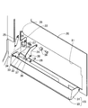
- An opening 21 is formed in the frame 20 of the housing 10 so as to correspond to the opening 13 where the passbook operation port 12 of the front panel 11 is located, for example, and base plates 22 are provided at both ends of the opening 21 in the width direction. It is integrally formed.
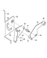
- the base plate 22 constitutes a shutter mechanism together with the shutter member 23, the shutter drive lever 24, and a tension coil spring (first elastic body) 25. Further, the shutter mechanism is a tension coil for adding a function of a lock mechanism.
- a spring (second elastic body) 26 is provided.
- the base plate 22 is provided with a fixed shaft 27 that pivotally supports the shutter member 23 and the shutter drive lever 24 on the side of the opposing surface.
- the base plate 22 is provided with a retaining groove 28 and an arc-shaped slit 29.
- the latching groove 28 has a rectangular shape extending toward the center of the fixed shaft 27, and the arc-shaped slit 29 has an arc shape centered on the fixed shaft 27. What is the fixed shaft 27 of the latching groove 28? Connected at the opposite end to form a continuous groove.
- the shutter member 23 includes a shutter plate 30 that closes or opens the opening 13 and brackets 31 provided at both ends of the shutter plate 30 in the width direction.
- the bracket 31 is provided with a shaft hole 32 and a retaining hole 33, and a spring retaining hole 34 is formed in the upper portion of the shutter plate 30 close to the connection portion with the bracket 31.
- the shaft hole 32 has a first rotation position where the shutter plate 30 closes the opening 13 by the insertion of the fixed shaft 27 and a space below the passbook operation port 12 when the unit is in the storage position.
- the shutter member 23 is pivotally supported so that the shutter member 23 can be rotated between the second rotation position and the second rotation position.
- the retaining hole 33 has a shape of a long hole, and its long axis is directed in a direction passing through the center of the fixed shaft 27.
- the spring latching hole 34 is for latching one end of the tension coil spring 25 that urges the shutter member 23 to the first rotation position, and the other end of the tension coil spring 25 is formed in the frame 20. It is latched by the spring latching hole 35 made.
- the shutter drive lever 24 has a roller 36 attached to one end thereof, a latch pin 37 fixed to the other end, a shaft hole 38 through which the fixed shaft 27 passes, and one end of the tension coil spring 26. And a spring latching portion 39 to be stopped.
- the roller 36 is for reducing contact resistance when a lever provided in the unit comes into contact.
- the latch pin 37 extends into the latch groove 28 and the arc-shaped slit 29 drilled in the base plate 22 through the latch hole 33 drilled in the bracket 31.
- the shaft hole 38 through which the fixed shaft 27 is inserted has a shape of a long hole, and the long axis is directed in a direction passing through the center of the latch pin 37.
- the spring latching portion 39 is formed integrally with the shutter drive lever 24 on the extended line of the long axis of the shaft hole 38.
- the other end of the tension coil spring 26 whose one end is hooked on the spring hooking portion 39 is hooked on a fixed shaft 27 that pivotally supports the shutter drive lever 24.
- the fixed shaft 27 is fixed to the base plate 22 through the shaft hole 32 of the bracket 31, and the tension coil spring 25 is connected to the spring retaining hole 34 of the shutter plate 30 and the spring retaining hole 35 of the frame 20.
- the shutter member 23 is pivotally attached and is urged to maintain the shutter member 23 in the first rotational position.
- the shutter drive lever 24 has its latch pin 37 inserted into the latch groove 28 of the base plate 22 through the latch hole 33 of the bracket 31, and the fixed shaft 27 is passed through the shaft hole 38, and the washer is fixed to the fixed shaft 27. And by attaching the retaining ring, the shutter member 23 becomes rotatable.
- the tension coil spring 26 is latched by the spring latching portion 39 of the shutter drive lever 24 and the fixed shaft 27, thereby energizing the shutter drive lever 24 to be always pulled toward the fixed shaft 27, and the shutter.
- the latch pin 37 is latched in the latch groove 28 of the base plate 22, and the shutter member 23 is locked.
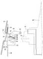
- FIG. 5 is a side view showing a state in which the unit is pulled out from the storage position and the shutter member is locked.
- FIG. 6 is a diagram showing the unit moving from the pull-out position toward the storage position, and the lever on the unit side contacts the roller.
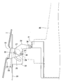
- FIG. 7 is a side view showing a state where the lever on the unit side unlocks the shutter member
- FIG. 8 is a side view showing a state where the shutter member is rotating
- FIG. 9 is a side view showing the unit. It is a side view which shows the state returned to the storage position.
- the unit 40 is mounted on a pair of telescopic slide rails and is housed in the housing 10 so that it can easily reciprocate between a storage position during normal operation and a drawer position during maintenance. ing.
- a lever 41 is provided at the front end side of the unit 40, and this operates the shutter mechanism in conjunction with the storing / drawing operation of the unit 40.
- the shutter member 23 is pulled up by the tension coil spring 25, so that it rotates in the clockwise direction around the fixed shaft 27. Rotation is stopped at a position where the latch pin 37 of the shutter drive lever 24 contacts the upper end of the arc-shaped slit 29. At this time, the shutter plate 30 of the shutter member 23 is in the first rotation position where the opening 13 is closed. At the same time, since the tension coil spring 26 pulls the shutter drive lever 24 in the direction of the fixed shaft 27, the latch pin 37 of the shutter drive lever 24 moves from the arc-shaped slit 29 to the latch groove 28.
- the shutter drive lever 24 becomes non-rotatable, and the latch hole 33 is latched by the non-rotatable latch pin 37 so that the shutter member 23 is also non-rotatable and locked. It has become. Therefore, in a state where the shutter mechanism closes the opening 13 and is locked, the shutter cannot be opened even if the shutter plate 30 receives an external force that pushes down through the opening 13.
- the shutter drive lever 24 causes the latch pin 37 to rotate the bracket 31 counterclockwise to the lower end of the arc-shaped slit 29.
- the shutter plate 30 of the shutter member 23 has been moved to the second rotational position, that is, the space below the passbook operation port 12, which is the storage location.
- the unit 40 is locked by a lock mechanism (not shown), and the passbook operation port 12 projects from the opening 13.
- the unit 40 when storing the unit 40 that has been pulled out for maintenance, the unit 40 is simply moved in the storing direction to release the lock first, and the shutter member 23 is moved by the series of storing operations. The operation of rotating to open the opening 13 can be continuously performed.
- the retaining groove 28 formed in the base plate 22 is formed in a rectangular shape, but can be formed in an oval shape. Further, the arc-shaped slit 29 need only be rotated in a state in which the latch pin 37 is kept at a fixed distance from the fixed shaft 27, so that the arc-shaped slit 29 does not need to have a slit shape, and an arc-shaped wall is formed on the fixed shaft 27 side. It can be set as the notch which has.
- latching groove 28 and the arc-shaped slit 29 are formed through the base plate 22, the latching groove 37 and the arc-shaped slit 29 are adapted to the movement locus of the latching pin 37 during the lock / unlock operation and the rotation operation of the shutter drive lever 24.
- a recessed groove may be used.
Landscapes
- Physics & Mathematics (AREA)
- General Physics & Mathematics (AREA)
- Business, Economics & Management (AREA)
- Accounting & Taxation (AREA)
- Finance (AREA)
- Engineering & Computer Science (AREA)
- Mechanical Engineering (AREA)
- Financial Or Insurance-Related Operations Such As Payment And Settlement (AREA)
- Devices For Checking Fares Or Tickets At Control Points (AREA)
Abstract
Description
図1は現金自動取引装置の外観を示す斜視図、図2は現金自動取引装置のシャッタ搭載部を示す拡大図である。図2の例では、現金自動取引装置に2台のユニットが搭載されている状態を示している。
筐体10のフレーム20には、前面パネル11のたとえば通帳操作口12が位置する開口部13に対応して開口部21が形成されており、その開口部21の幅方向両端側にベースプレート22が一体に形成されている。このベースプレート22は、シャッタ部材23、シャッタ駆動レバー24および引張コイルばね(第1の弾性体)25とともにシャッタ機構を構成し、さらに、このシャッタ機構は、ロック機構の機能を付加するために引張コイルばね(第2の弾性体)26を備えている。
図5はユニットがその収納位置から引き出されてシャッタ部材がロックされている状態を示す側面図、図6はユニットが引き出し位置から収納位置の方へ移動してユニット側のレバーがローラに当接した状態を示す側面図、図7はユニット側のレバーがシャッタ部材のロックを解除した状態を示す側面図、図8はシャッタ部材が回動している状態を示す側面図、図9はユニットをその収納位置に戻した状態を示す側面図である。
11 前面パネル
12 通帳操作口
13 開口部
14 カード操作口
15 開口部
16 硬貨を取り扱うユニット
17 紙幣を取り扱うユニット
18 表示・操作を行うユニット
20 フレーム
21 開口部
22 ベースプレート
23 シャッタ部材
24 シャッタ駆動レバー
25,26 引張コイルばね
27 固定軸
28 掛止溝
29 弧状スリット
30 シャッタ板
31 ブラケット
32 軸孔
33 掛止孔
34,35 ばね掛止孔
36 ローラ
37 掛止ピン
38 軸孔
39 ばね掛止部
40 ユニット
41 レバー
Claims (5)
- 収納時に、筐体の接客面側の正面パネルに設けられた開口部に操作口が位置し、メンテナンス時には、収納位置から前記筐体の背面側へ引き出すことができるように前記筐体内に引き出し自在に装着された少なくとも1つのユニットと、前記ユニットの引き出し動作に連動して前記開口部を閉鎖するシャッタ機構とを備えた現金自動取引装置において、
前記シャッタ機構は、
前記開口部の幅方向両端の近傍に対向して前記筐体のフレームに固設され、対向面側にそれぞれ固定軸が設けられたベースプレートと、
前記開口部を閉鎖または開放するシャッタ板および前記シャッタ板の幅方向両端に設けられたブラケットを有し、前記シャッタ板が前記開口部を閉鎖する第1の回動位置と前記ユニットが収納されたときの前記操作口の下部に前記シャッタ板が位置する第2の回動位置との間で回動できるよう前記ブラケットが前記固定軸によって軸支されたシャッタ部材と、
前記固定軸に回動自在に軸支され、前記ユニットがその収納位置まで移動されるとき前記ユニットにより一端が収納方向に押されることで他端に設けられて前記ブラケットに掛止されている掛止ピンが前記シャッタ板を前記第1の回動位置から前記第2の回動位置まで回動させるシャッタ駆動レバーと、
前記ユニットがその収納位置から引き出されたときに前記シャッタ部材を前記第1の回動位置まで回動するように付勢する第1の弾性体と、
を備え、
前記シャッタ駆動レバーの前記固定軸が貫通する軸孔は、前記固定軸および前記掛止ピンの中心を通る中心線の方向に長軸を有する長孔形状に穿設され、
前記ブラケットの前記掛止ピンが貫通する掛止孔は、前記固定軸および前記掛止孔の中心を通る中心線の方向に長軸を有する長孔形状に穿設され、
前記ベースプレートは、前記シャッタ駆動レバーが前記軸孔の長軸の長さ方向に往復運動するときの前記掛止ピンの移動軌跡に沿って形成された掛止溝と、前記掛止溝の前記固定軸とは反対側の端部に接続されて前記シャッタ板を前記第1の回動位置から前記第2の回動位置まで回動させるときの前記掛止ピンの移動を許容する切欠き部とを有し、
前記シャッタ駆動レバーを前記掛止ピンから前記軸孔に向けて常時付勢することにより、前記シャッタ板が前記第1の回動位置にあるとき、前記掛止ピンを前記掛止溝に掛止させる第2の弾性体を備えてロック機構を構成したことを特徴とする現金自動取引装置。 - 前記シャッタ駆動レバーは、前記ユニットに当接する側の一端にローラを有していることを特徴とする請求の範囲第1項記載の現金自動取引装置。
- 前記シャッタ駆動レバーは、前記ユニットに設けたレバーによって駆動されることを特徴とする請求の範囲第1項記載の現金自動取引装置。
- 前記ベースプレートは、前記掛止溝を長孔または長方形の形状に穿設し、前記切欠き部を前記固定軸を中心とした円弧状のスリットを穿設することで形成していることを特徴とする請求の範囲第1項記載の現金自動取引装置。
- 前記ベースプレートは、前記開口部の内側に配置されるフレームと一体に形成されていることを特徴とする請求の範囲第1項記載の現金自動取引装置。
Priority Applications (4)
| Application Number | Priority Date | Filing Date | Title |
|---|---|---|---|
| KR1020117005465A KR101148387B1 (ko) | 2009-06-30 | 2009-06-30 | 현금 자동 거래 장치 |
| CN2009801364411A CN102160094B (zh) | 2009-06-30 | 2009-06-30 | 现金自动交易装置 |
| PCT/JP2009/061933 WO2011001505A1 (ja) | 2009-06-30 | 2009-06-30 | 現金自動取引装置 |
| JP2011520697A JP5215465B2 (ja) | 2009-06-30 | 2009-06-30 | 現金自動取引装置 |
Applications Claiming Priority (1)
| Application Number | Priority Date | Filing Date | Title |
|---|---|---|---|
| PCT/JP2009/061933 WO2011001505A1 (ja) | 2009-06-30 | 2009-06-30 | 現金自動取引装置 |
Publications (1)
| Publication Number | Publication Date |
|---|---|
| WO2011001505A1 true WO2011001505A1 (ja) | 2011-01-06 |
Family
ID=43410603
Family Applications (1)
| Application Number | Title | Priority Date | Filing Date |
|---|---|---|---|
| PCT/JP2009/061933 Ceased WO2011001505A1 (ja) | 2009-06-30 | 2009-06-30 | 現金自動取引装置 |
Country Status (4)
| Country | Link |
|---|---|
| JP (1) | JP5215465B2 (ja) |
| KR (1) | KR101148387B1 (ja) |
| CN (1) | CN102160094B (ja) |
| WO (1) | WO2011001505A1 (ja) |
Cited By (9)
| Publication number | Priority date | Publication date | Assignee | Title |
|---|---|---|---|---|
| CN102733704A (zh) * | 2011-03-29 | 2012-10-17 | 富士通先端科技株式会社 | 开闭部件的开闭机构 |
| JP2014092901A (ja) * | 2012-11-02 | 2014-05-19 | Oki Electric Ind Co Ltd | シャッタ機構、及び、当該シャッタ機構を実装する自動取引装置 |
| JP2015176290A (ja) * | 2014-03-14 | 2015-10-05 | 沖電気工業株式会社 | シャッタ開閉装置及び媒体授受装置 |
| JP2015185128A (ja) * | 2014-03-26 | 2015-10-22 | 沖電気工業株式会社 | 開閉装置 |
| CN107862788A (zh) * | 2017-11-22 | 2018-03-30 | 深圳怡化电脑股份有限公司 | 一种介质鉴别终端及金融自助终端 |
| JP2019046074A (ja) * | 2017-08-31 | 2019-03-22 | 富士通フロンテック株式会社 | 投票券処理装置 |
| CN115095192A (zh) * | 2022-06-21 | 2022-09-23 | 江西建邦科技有限公司 | 一种装配式生态浇灌公共厕所 |
| JP2023103130A (ja) * | 2022-01-13 | 2023-07-26 | 富士通フロンテック株式会社 | 貨幣取扱装置 |
| JP2024088541A (ja) * | 2022-12-20 | 2024-07-02 | 富士通フロンテック株式会社 | 貨幣取扱装置 |
Families Citing this family (9)
| Publication number | Priority date | Publication date | Assignee | Title |
|---|---|---|---|---|
| JP5365672B2 (ja) * | 2011-09-22 | 2013-12-11 | 沖電気工業株式会社 | 自動取引装置 |
| CN102568087A (zh) * | 2011-12-31 | 2012-07-11 | 东方通信股份有限公司 | 自动柜员机机壳存取款口防护装置 |
| JP5527347B2 (ja) * | 2012-03-26 | 2014-06-18 | 沖電気工業株式会社 | 紙葉類収納庫及び紙葉類取扱装置 |
| JP5919953B2 (ja) * | 2012-03-29 | 2016-05-18 | 沖電気工業株式会社 | 引出装置及び媒体取引装置 |
| JP6225409B2 (ja) * | 2012-05-16 | 2017-11-08 | 沖電気工業株式会社 | 自動取引装置 |
| JP5971119B2 (ja) * | 2012-12-28 | 2016-08-17 | 沖電気工業株式会社 | シャッタ装置及び媒体取引装置 |
| CN103903330B (zh) * | 2014-03-11 | 2016-06-15 | 杭州九聚科技有限公司 | 一种旋转板式金融自助设备出钞闸门 |
| CN109747771B (zh) * | 2017-11-02 | 2024-10-29 | 南通中远海运川崎船舶工程有限公司 | 一种轻便型可转动收藏的船用组装式平台 |
| CN108171870B (zh) * | 2018-02-07 | 2024-02-06 | 深圳怡化电脑股份有限公司 | 一种接客模块及自助金融设备 |
Citations (2)
| Publication number | Priority date | Publication date | Assignee | Title |
|---|---|---|---|---|
| JP2004110640A (ja) * | 2002-09-20 | 2004-04-08 | Oki Electric Ind Co Ltd | 顧客操作口シャッタロック機構 |
| WO2008111148A1 (ja) * | 2007-03-12 | 2008-09-18 | Glory Ltd. | シャッタ装置 |
Family Cites Families (2)
| Publication number | Priority date | Publication date | Assignee | Title |
|---|---|---|---|---|
| CN201215668Y (zh) * | 2008-03-11 | 2009-04-01 | 广州广电运通金融电子股份有限公司 | 一种双层滑动闸门机构 |
| CN101425200B (zh) * | 2008-11-17 | 2010-08-11 | 广州广电运通金融电子股份有限公司 | 暂存装置 |
-
2009
- 2009-06-30 CN CN2009801364411A patent/CN102160094B/zh not_active Expired - Fee Related
- 2009-06-30 WO PCT/JP2009/061933 patent/WO2011001505A1/ja not_active Ceased
- 2009-06-30 JP JP2011520697A patent/JP5215465B2/ja active Active
- 2009-06-30 KR KR1020117005465A patent/KR101148387B1/ko not_active Expired - Fee Related
Patent Citations (2)
| Publication number | Priority date | Publication date | Assignee | Title |
|---|---|---|---|---|
| JP2004110640A (ja) * | 2002-09-20 | 2004-04-08 | Oki Electric Ind Co Ltd | 顧客操作口シャッタロック機構 |
| WO2008111148A1 (ja) * | 2007-03-12 | 2008-09-18 | Glory Ltd. | シャッタ装置 |
Cited By (12)
| Publication number | Priority date | Publication date | Assignee | Title |
|---|---|---|---|---|
| CN102733704A (zh) * | 2011-03-29 | 2012-10-17 | 富士通先端科技株式会社 | 开闭部件的开闭机构 |
| JP2014092901A (ja) * | 2012-11-02 | 2014-05-19 | Oki Electric Ind Co Ltd | シャッタ機構、及び、当該シャッタ機構を実装する自動取引装置 |
| JP2015176290A (ja) * | 2014-03-14 | 2015-10-05 | 沖電気工業株式会社 | シャッタ開閉装置及び媒体授受装置 |
| JP2015185128A (ja) * | 2014-03-26 | 2015-10-22 | 沖電気工業株式会社 | 開閉装置 |
| JP2019046074A (ja) * | 2017-08-31 | 2019-03-22 | 富士通フロンテック株式会社 | 投票券処理装置 |
| CN107862788A (zh) * | 2017-11-22 | 2018-03-30 | 深圳怡化电脑股份有限公司 | 一种介质鉴别终端及金融自助终端 |
| JP2023103130A (ja) * | 2022-01-13 | 2023-07-26 | 富士通フロンテック株式会社 | 貨幣取扱装置 |
| JP7606480B2 (ja) | 2022-01-13 | 2024-12-25 | 富士通フロンテック株式会社 | 貨幣取扱装置 |
| CN115095192A (zh) * | 2022-06-21 | 2022-09-23 | 江西建邦科技有限公司 | 一种装配式生态浇灌公共厕所 |
| CN115095192B (zh) * | 2022-06-21 | 2023-06-16 | 江西建邦科技有限公司 | 一种装配式生态浇灌公共厕所 |
| JP2024088541A (ja) * | 2022-12-20 | 2024-07-02 | 富士通フロンテック株式会社 | 貨幣取扱装置 |
| JP7774551B2 (ja) | 2022-12-20 | 2025-11-21 | 株式会社富士通フロンテックシステムズ | 貨幣取扱装置 |
Also Published As
| Publication number | Publication date |
|---|---|
| KR20110051242A (ko) | 2011-05-17 |
| KR101148387B1 (ko) | 2012-05-21 |
| JP5215465B2 (ja) | 2013-06-19 |
| CN102160094B (zh) | 2013-01-23 |
| JPWO2011001505A1 (ja) | 2012-12-10 |
| CN102160094A (zh) | 2011-08-17 |
Similar Documents
| Publication | Publication Date | Title |
|---|---|---|
| JP5215465B2 (ja) | 現金自動取引装置 | |
| EP2458125B1 (en) | Cash box provided with self-locking mechanism | |
| US6843409B2 (en) | Media container module | |
| JP4480122B2 (ja) | 貸出機および貸出機システム | |
| JP5355427B2 (ja) | 自動取引装置のシャッタ構造 | |
| JP2004121512A (ja) | 遊技機のパネル開閉装置 | |
| WO2019218913A1 (zh) | 闸门机构、钞箱及自助设备 | |
| CN112365650B (zh) | 硬币存储箱及硬币存储系统 | |
| KR20100080029A (ko) | 금융자동화기기의 표시장치 | |
| JP6120135B2 (ja) | 錠装置及びこれを備えた収納装置 | |
| JP7774551B2 (ja) | 貨幣取扱装置 | |
| JP7606480B2 (ja) | 貨幣取扱装置 | |
| JP7700619B2 (ja) | 現金取扱装置、及び、扉同時開き防止構造 | |
| JP5906207B2 (ja) | カバーロック装置 | |
| JP6527769B2 (ja) | 金銭処理機 | |
| JP5835816B2 (ja) | キャッシュドロア | |
| JP2013014977A (ja) | ロック装置 | |
| KR101428167B1 (ko) | 잠금장치 및 이를 이용한 금융기기 | |
| JP6744659B2 (ja) | 券売機および券売機拡張装置 | |
| JP2024078869A (ja) | 宅配ロッカー | |
| KR200350040Y1 (ko) | 현금자동지급기의 잠금장치 | |
| JP2003006704A (ja) | 硬貨回収金庫、および自動販売機 | |
| JP4597025B2 (ja) | 電気錠 | |
| JP6020049B2 (ja) | シャッタ機構、及び、当該シャッタ機構を実装する自動取引装置 | |
| WO2025204018A1 (ja) | 施錠開閉装置 |
Legal Events
| Date | Code | Title | Description |
|---|---|---|---|
| WWE | Wipo information: entry into national phase |
Ref document number: 200980136441.1 Country of ref document: CN |
|
| ENP | Entry into the national phase |
Ref document number: 2011520697 Country of ref document: JP Kind code of ref document: A |
|
| 121 | Ep: the epo has been informed by wipo that ep was designated in this application |
Ref document number: 09846798 Country of ref document: EP Kind code of ref document: A1 |
|
| ENP | Entry into the national phase |
Ref document number: 20117005465 Country of ref document: KR Kind code of ref document: A |
|
| NENP | Non-entry into the national phase |
Ref country code: DE |
|
| 122 | Ep: pct application non-entry in european phase |
Ref document number: 09846798 Country of ref document: EP Kind code of ref document: A1 |