WO2010150405A1 - ろ過方法及び膜ろ過装置 - Google Patents
ろ過方法及び膜ろ過装置 Download PDFInfo
- Publication number
- WO2010150405A1 WO2010150405A1 PCT/JP2009/061753 JP2009061753W WO2010150405A1 WO 2010150405 A1 WO2010150405 A1 WO 2010150405A1 JP 2009061753 W JP2009061753 W JP 2009061753W WO 2010150405 A1 WO2010150405 A1 WO 2010150405A1
- Authority
- WO
- WIPO (PCT)
- Prior art keywords
- filtration
- pressure
- raw water
- membrane
- water side
- Prior art date
- Legal status (The legal status is an assumption and is not a legal conclusion. Google has not performed a legal analysis and makes no representation as to the accuracy of the status listed.)
- Ceased
Links
Images




Classifications
-
- B—PERFORMING OPERATIONS; TRANSPORTING
- B01—PHYSICAL OR CHEMICAL PROCESSES OR APPARATUS IN GENERAL
- B01D—SEPARATION
- B01D61/00—Processes of separation using semi-permeable membranes, e.g. dialysis, osmosis or ultrafiltration; Apparatus, accessories or auxiliary operations specially adapted therefor
- B01D61/14—Ultrafiltration; Microfiltration
- B01D61/22—Controlling or regulating
-
- B—PERFORMING OPERATIONS; TRANSPORTING
- B01—PHYSICAL OR CHEMICAL PROCESSES OR APPARATUS IN GENERAL
- B01D—SEPARATION
- B01D35/00—Filtering devices having features not specifically covered by groups B01D24/00 - B01D33/00, or for applications not specifically covered by groups B01D24/00 - B01D33/00; Auxiliary devices for filtration; Filter housing constructions
- B01D35/14—Safety devices specially adapted for filtration; Devices for indicating clogging
-
- B—PERFORMING OPERATIONS; TRANSPORTING
- B01—PHYSICAL OR CHEMICAL PROCESSES OR APPARATUS IN GENERAL
- B01D—SEPARATION
- B01D61/00—Processes of separation using semi-permeable membranes, e.g. dialysis, osmosis or ultrafiltration; Apparatus, accessories or auxiliary operations specially adapted therefor
- B01D61/14—Ultrafiltration; Microfiltration
-
- B—PERFORMING OPERATIONS; TRANSPORTING
- B01—PHYSICAL OR CHEMICAL PROCESSES OR APPARATUS IN GENERAL
- B01D—SEPARATION
- B01D63/00—Apparatus in general for separation processes using semi-permeable membranes
-
- B—PERFORMING OPERATIONS; TRANSPORTING
- B01—PHYSICAL OR CHEMICAL PROCESSES OR APPARATUS IN GENERAL
- B01D—SEPARATION
- B01D65/00—Accessories or auxiliary operations, in general, for separation processes or apparatus using semi-permeable membranes
- B01D65/02—Membrane cleaning or sterilisation ; Membrane regeneration
-
- C—CHEMISTRY; METALLURGY
- C02—TREATMENT OF WATER, WASTE WATER, SEWAGE, OR SLUDGE
- C02F—TREATMENT OF WATER, WASTE WATER, SEWAGE, OR SLUDGE
- C02F1/00—Treatment of water, waste water, or sewage
- C02F1/44—Treatment of water, waste water, or sewage by dialysis, osmosis or reverse osmosis
- C02F1/444—Treatment of water, waste water, or sewage by dialysis, osmosis or reverse osmosis by ultrafiltration or microfiltration
-
- B—PERFORMING OPERATIONS; TRANSPORTING
- B01—PHYSICAL OR CHEMICAL PROCESSES OR APPARATUS IN GENERAL
- B01D—SEPARATION
- B01D2311/00—Details relating to membrane separation process operations and control
- B01D2311/14—Pressure control
-
- B—PERFORMING OPERATIONS; TRANSPORTING
- B01—PHYSICAL OR CHEMICAL PROCESSES OR APPARATUS IN GENERAL
- B01D—SEPARATION
- B01D2311/00—Details relating to membrane separation process operations and control
- B01D2311/16—Flow or flux control
-
- B—PERFORMING OPERATIONS; TRANSPORTING
- B01—PHYSICAL OR CHEMICAL PROCESSES OR APPARATUS IN GENERAL
- B01D—SEPARATION
- B01D2311/00—Details relating to membrane separation process operations and control
- B01D2311/24—Quality control
-
- B—PERFORMING OPERATIONS; TRANSPORTING
- B01—PHYSICAL OR CHEMICAL PROCESSES OR APPARATUS IN GENERAL
- B01D—SEPARATION
- B01D2321/00—Details relating to membrane cleaning, regeneration, sterilization or to the prevention of fouling
- B01D2321/04—Backflushing
-
- C—CHEMISTRY; METALLURGY
- C02—TREATMENT OF WATER, WASTE WATER, SEWAGE, OR SLUDGE
- C02F—TREATMENT OF WATER, WASTE WATER, SEWAGE, OR SLUDGE
- C02F2209/00—Controlling or monitoring parameters in water treatment
- C02F2209/001—Upstream control, i.e. monitoring for predictive control
-
- C—CHEMISTRY; METALLURGY
- C02—TREATMENT OF WATER, WASTE WATER, SEWAGE, OR SLUDGE
- C02F—TREATMENT OF WATER, WASTE WATER, SEWAGE, OR SLUDGE
- C02F2209/00—Controlling or monitoring parameters in water treatment
- C02F2209/005—Processes using a programmable logic controller [PLC]
-
- C—CHEMISTRY; METALLURGY
- C02—TREATMENT OF WATER, WASTE WATER, SEWAGE, OR SLUDGE
- C02F—TREATMENT OF WATER, WASTE WATER, SEWAGE, OR SLUDGE
- C02F2209/00—Controlling or monitoring parameters in water treatment
- C02F2209/03—Pressure
-
- C—CHEMISTRY; METALLURGY
- C02—TREATMENT OF WATER, WASTE WATER, SEWAGE, OR SLUDGE
- C02F—TREATMENT OF WATER, WASTE WATER, SEWAGE, OR SLUDGE
- C02F2209/00—Controlling or monitoring parameters in water treatment
- C02F2209/11—Turbidity
-
- C—CHEMISTRY; METALLURGY
- C02—TREATMENT OF WATER, WASTE WATER, SEWAGE, OR SLUDGE
- C02F—TREATMENT OF WATER, WASTE WATER, SEWAGE, OR SLUDGE
- C02F2209/00—Controlling or monitoring parameters in water treatment
- C02F2209/20—Total organic carbon [TOC]
-
- C—CHEMISTRY; METALLURGY
- C02—TREATMENT OF WATER, WASTE WATER, SEWAGE, OR SLUDGE
- C02F—TREATMENT OF WATER, WASTE WATER, SEWAGE, OR SLUDGE
- C02F2209/00—Controlling or monitoring parameters in water treatment
- C02F2209/40—Liquid flow rate
Definitions
- the present invention relates to a filtration method and a membrane filtration for filtering water, industrial water, river water, lake water, ground water, storage water, secondary treated water of sewage, sewage, waste water, etc. using a membrane module as a driving force. Relates to the device.
- Raw water side pressure filtration is a method in which the raw water side of the membrane is pressurized, and the filtered water side is normally opened to atmospheric pressure to create a pressure difference (membrane differential pressure) between the raw water side of the membrane and the filtrate water side. is there.
- the filtered water-side vacuum filtration is a method in which the raw water side of the membrane is usually opened to atmospheric pressure, and the filtered water side is decompressed to generate a membrane differential pressure and perform filtration.
- membrane contamination the substance causing membrane contamination is referred to as “membrane contamination causing substance”.
- membrane filtration flow the membrane differential pressure rises as the operation of the bundle is continued.
- chemical cleaning is required, but it is preferable that the number of chemical cleaning be small in view of both cost and environmental load. In other words, in continuing the membrane filtration operation, it is desirable to suppress an increase in the membrane differential pressure while ensuring a constant amount of membrane filtration flux for a long period of time.
- the liquid supplied in the intermembrane flow path is circulated with the pressure of the circulation pump to wash the film, and the liquid is filtered through a filtration membrane using a suction pump.
- a membrane treatment method for taking out water is described in JP-A-11-300188. Japanese Patent Laid-Open No. 11-300188
- the power for taking out the filtrate depends on the suction force of the suction pump and does not substantially depend on the pressure of the circulation pump.
- the design filtration flux may not be secured.
- An object of the present invention is to provide a filtration method and a membrane filtration device that can suppress an increase in membrane differential pressure while maintaining a designed membrane filtration flux and can continue a stable filtration operation for a long time.
- the present invention provides: (1) A filtration method for obtaining filtered water by filtering a raw water by performing a filtration operation using a pressure as a driving force for the membrane module, the filtration operation comprising a raw water side pressure filtration and a filtration It consists of three aspects of water-side vacuum filtration and combined filtration that combines the raw water-side pressure filtration and the filtered water-side vacuum filtration, and measures at least one of raw water-side water quality, membrane filtration flux, and membrane differential pressure. Depending on the measured value, the filtration method is characterized by switching from any one of the three aspects to another filtration.
- the measured value is a characteristic value X representing a concentration of a membrane contamination causative substance calculated from the raw water side water quality, and when the characteristic value X is below a preset threshold value, the raw water side pressurization Filtration is performed, and when the characteristic value X exceeds the threshold, the raw water side pressure filtration is switched to the composite filtration.
- the measured value is a membrane filtration flux, and when the measured value falls below a preset membrane filtration flux during a constant flow filtration operation at a design flow rate by the filtered water-side vacuum filtration, The filtration method according to the above (1), wherein the filtered water side vacuum filtration is switched to the raw water side pressure filtration or the combined filtration.
- the measured value is a suction head on the filtrate side corresponding to the membrane differential pressure
- a membrane filtration apparatus including a membrane module using pressure as a driving force, the first pressure adjusting means for adjusting the raw water side pressure of the membrane module, and the filtrate side pressure of the membrane module A second pressure adjusting unit; a measuring unit that measures water quality on the raw water side of the membrane module; and the first pressure adjusting unit and the second pressure adjusting unit based on a measurement value measured by the measuring unit.
- Control means for driving and controlling at least one of the means comprising: raw water side pressure filtration, filtered water side vacuum filtration, combined filtration of the raw water side pressure filtration and filtered water side vacuum filtration, Of these three aspects, switching from one filtration to another is characterized.
- the membrane filtration device wherein the second pressure adjusting means is a vacuum pump, and the measuring means is at least one of a turbidimeter and a total organic carbon content measuring device.
- the control means drives and controls at least one of the first pressure regulating means and the second pressure regulating means, and pressurization backwash that pressurizes the filtrate water side and decompresses the raw water side.
- the backwashing is carried out by any one of a backwashing under reduced pressure and a combined backwashing combined with a backwashing under pressure in which the filtered water side is pressurized and under reduced pressure backwashing under reduced pressure on the raw water side.
- the present invention it is possible to suppress an increase in the membrane differential pressure while maintaining the designed membrane filtration flux and to continue a stable filtration operation for a long time.
- FIG. 1 is an explanatory diagram illustrating a schematic configuration of a membrane filtration apparatus that can switch between raw water-side pressure filtration, filtered water-side vacuum filtration, and composite filtration according to an embodiment of the present invention.
- FIG. 2 is an explanatory diagram showing the flow of fluid in the filtration step of the raw water side pressure filtration in the membrane filtration device according to the present embodiment.
- Drawing 3 is an explanatory view showing the flow of the fluid in the filtration process of filtration water side vacuum filtration, or the filtration process of compound filtration.
- FIG. 4 is an explanatory diagram showing the flow of fluid in a cleaning process in which backwashing and gas cleaning are simultaneously performed in connection with filtered water pressure backwashing.
- FIG. 1 is an explanatory diagram illustrating a schematic configuration of a membrane filtration apparatus that can switch between raw water-side pressure filtration, filtered water-side vacuum filtration, and composite filtration according to an embodiment of the present invention.
- FIG. 2 is an explanatory diagram showing the flow of fluid
- FIG. 5 is an explanatory diagram showing a flow of fluid in a cleaning process in which backwashing and gas cleaning are performed simultaneously in connection with raw water side reduced pressure backwashing or combined backwashing.
- FIG. 6 is an explanatory view showing the flow of fluid in the discharging step of discharging the peeled off substance to be removed from the membrane module.
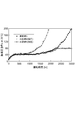
- FIG. 7 is a diagram showing the film differential pressure change characteristics in Example 1, Comparative Example 1, and Comparative Example 2.
- FIG. 8 is a graph showing turbidity change characteristics in Example 1, Comparative Example 1, and Comparative Example 2.
- FIG. 9 is a diagram showing the membrane filtration flux variation characteristics in Example 1, Comparative Example 1, and Comparative Example 2.
- FIG. 10 is a diagram showing the film differential pressure change characteristics in Example 2 and Comparative Example 3.
- FIG. 11 is a diagram showing the film differential pressure change characteristics in Example 3, Comparative Example 4, and Comparative Example 5.
- FIG. 12 is a diagram showing the membrane filtration flux variation characteristics in Example 3, Comparative Example 4, and Comparative Example 5.
- FIG. 13 is a diagram showing the film differential pressure change characteristics in Example 4, Comparative Example 6, and Comparative Example 7.
- FIG. 14 is a diagram showing the membrane filtration flux variation characteristics in Example 4, Comparative Example 6, and Comparative Example 7.
- a membrane filtration device 50 includes a membrane module 4 in which a solid-liquid separation membrane (hereinafter referred to as “membrane”) is accommodated in a case.
- the membrane filtration apparatus 50 is equipment for obtaining filtered water by separating and removing suspended substances and substances having a size larger than the pore diameter of the membrane from the raw water 1 by the membrane module 4 using the pressure as a driving force.
- the membrane according to this embodiment is a polyvinylidene fluoride (PVDF) hollow fiber microfiltration (MF) membrane having an inner diameter of 0.7 mm ⁇ , an outer diameter of 1.2 mm ⁇ , and an average pore diameter of 0.1 ⁇ m, and the outer surface area of the hollow fiber.
- PVDF polyvinylidene fluoride
- MF hollow fiber microfiltration
- the effective membrane area of the membrane module 4 taken out from the above is 7.4 m 2 .
- the membrane module 4 is an external pressure raw water side pressure filtration module housed in a 1 m long, 84 mm diameter polyvinyl chloride (PVC) casing.
- the material of the membrane is not particularly limited, but for example, polyolefins such as polyethylene, polypropylene, polybutene; tetrafluoroethylene-perfluoroalkyl vinyl ether copolymer (PFA), tetrafluoroethylene-hexafluoropropylene copolymer (FEP) , Tetrafluoroethylene-hexafluoropropylene-perfluoroalkyl vinyl ether copolymer (EPE), tetrafluoroethylene-ethylene copolymer (ETFE), polychlorotrifluoroethylene (PCTFE), chlorotrifluoroethylene-ethylene copolymer Fluorine resins such as (ECTFE) and polyvinylidene fluoride (PVDF); polysulfone, polyethersulfone, polyetherketone, polyetheretherketone, polyphenylenes Cellulose acetate, cellulose such as ethyl cellulose; super engineering plastics such as Fido poly
- any shape such as a hollow fiber shape, a flat membrane shape, a pleated shape, a spiral shape or a tubular shape can be used.
- a hollow fiber shape is particularly preferred because of the high backwashing effect.
- both ends or one of the ends of a membrane bundle composed of a number of hollow fiber separation membranes are bonded and fixed, and one or both of the hollow fiber membranes at both ends Those having an open end are preferably used.
- the cross-sectional shape of the end part to be bonded and fixed may be a circle, a triangle, a quadrangle, a hexagon, an ellipse, or the like. Note that the membrane according to this embodiment and the membrane module 4 including the membrane are examples for explaining the present invention.
- the membrane filtration device 50 also introduces a raw water tank 2 that receives the raw water 1, a filtered water tank 6 that stores filtrate water that has permeated through the membrane module 4, and a raw water introduction that connects the raw water side inlet 4 a of the membrane module 4 and the raw water tank 2.
- the raw water circulation pipe 53 for returning the waste water from the pipe 51 and the drain side outlet 4c of the membrane module 4 to the raw water tank 2 is provided.
- the raw water introduction pipe 51 is provided with a pressure regulation filtration pump 3 that pumps the raw water 1 stored in the raw water tank 2 to the membrane module 4.
- the pressure regulation filtration pump 3 has an upstream side and a downstream side, respectively. Valves 14 and 24 are provided.
- An air introduction pipe 51 a is connected between the valve 24 on the downstream side of the pressure regulation filtration pump 3 and the membrane module 4.
- the air introduction pipe 51a is connected to the compressor 10 that supplies air for performing gas cleaning on the membrane of the membrane module 4, and a valve 22 is provided in the air introduction pipe 51a.
- the drainage discharge pipe 52 is provided with a valve 23 that opens the pipe when draining the drainage.
- the pressure regulation filtration pump 3 corresponds to first pressure regulation means for adjusting the raw water side pressure.
- the raw water introduction pipe 51 is connected to a first backwash water pipe 71 and a second backwash water pipe 72 that communicate with the raw water circulation pipe 53 and flows backwash water.
- the first backwash water pipe 71 and the second backwash water pipe 72 are for driving the pressure regulating filtration pump 3 to draw waste water from the drain side outlet 4 c of the membrane module 4 mouth and send it to the drain discharge pipe 52.
- Valves 26 and 27 are provided in the first backwash water pipe 71 and the second backwash water pipe 72, respectively.
- the raw water tank 2 is provided with an inlet 2a for the raw water 1, and further connected to a raw water circulation pipe 53 that communicates with the drain side outlet 4c of the membrane module 4.
- the raw water circulation pipe 53 is provided with a valve 15.
- the raw water tank 2 is provided with a water quality measuring device 11 for measuring the water quality on the raw water side.
- the water quality measuring device 11 is at least one of a turbidimeter and a total organic carbon content measuring device.
- the water quality measuring device 11 corresponds to a measuring means for measuring the water quality on the raw water side.
- the membrane filtration device 50 includes a filtrate water line 55 that connects the filtrate water side outlet 4 b of the membrane module 4 and the filtrate water tank 6.
- the filtrate water line 55 branches in two directions in the middle, and becomes a first pipe line 57 that feeds filtrate water to the filtrate water tank 6 in a state where one side is not decompressed, and the other side is decompressed to reduce the filtrate water to the membrane module 4. From this, the second pipe 58 is fed into the filtrate water tank 6.
- a valve 16 is provided at the entrance of the first pipeline 57, and a valve 17 is provided at the entrance of the second pipeline 58.
- the membrane filtration device 50 includes a raw water inlet pressure measuring device 12 a disposed in the raw water introduction conduit 51, a filtrate water pressure measuring device 12 b disposed in the filtered water conduit 55, and a raw water outlet disposed in the raw water circulation tube 53.
- a pressure measuring device 12c and a membrane filtration flux measuring device 13 are provided.
- the raw water inlet pressure measuring device 12a, the raw water outlet pressure measuring device 12c, and the filtered water side pressure measuring device 12b are devices that measure the pressure at each position, and the membrane filtration flux measuring device 13 flows through the first pipe 57. It is an instrument that measures the membrane filtration flux of filtered water.
- the second pipe 58 branches in two directions along the way, one side becomes a filtration side pipe 59 and the other side becomes a backwash side pipe 61.
- the filtration side pipe 59 is provided with a vacuum filtration pump 5, and valves 18 and 19 are provided on the upstream side and the downstream side, respectively, so as to sandwich the vacuum filtration pump 5.
- the backwash side pipe line 61 is provided with a pressure backwash pump 7, which is provided on the downstream side and the upstream side of the pressure backwash pump 7 on the basis of the flow direction of the backwash water.
- a valve 21 and a valve 20 are provided.
- the vacuum filtration pump 5 corresponds to a second pressure adjusting means for adjusting the filtrate water side pressure.
- the pressure regulation filtration pump 3 and the pressure reduction filtration pump 5 are connected in series so that the pressure regulation filtration pump 3 is provided on the raw water side of the membrane module 4 and the pressure reduction filtration pump 5 is provided on the filtration water side.
- the filtration pump 3 and the vacuum filtration pump 5 are arranged so that they can be turned on and off independently, it is also possible to adopt an arrangement other than this mode.
- the membrane filtration device 50 includes an oxidant tank 8 that stores an oxidant as a chemical solution, and a chemical solution supply line 63 that supplies the oxidant stored in the oxidant tank 8 to the membrane module 4. Yes.
- the chemical liquid supply pipe 63 is provided with an oxidant liquid feed pump 9, and further, a valve 25 is provided downstream of the oxidant liquid feed pump 9. The downstream end of the chemical liquid supply pipe 63 is connected to the filtered water pipe 55 at a position upstream of the branch point between the first pipe 57 and the second pipe 58.
- the membrane filtration apparatus 50 controls the backwash operation which performs simultaneously the filtration operation which filters the raw
- a control unit 40 is provided.
- the control unit 40 is connected to the pumps 3, 5, 7, 9 and the compressor 10 so as to be able to transmit and receive control signals.
- the control unit 40 is connected to each of the valves 14, 15, 16, 17, 18, 19, 20, 21, 22, 24, 25, 26, and 27 so as to be able to transmit and receive control signals.
- control unit 40 is connected so as to be able to receive the measurement value data relating to the water quality of the raw water 1 measured by the water quality measuring device 11, and further, the raw water inlet pressure measuring device 12a, the filtered water side pressure measuring device 12b, and the raw water outlet.
- the measurement value data related to the membrane differential pressure measured by the pressure measuring device 12c is connected so as to be receivable, and further the measurement value data related to the membrane filtration flux measured by the membrane filtration flux measuring device 13 is connected so as to be receivable. ing.
- the control unit 40 includes a central processing unit.
- the central processing unit includes a CPU, a RAM, a ROM, and the like as hardware configurations, and includes a control unit, a calculation unit, and a storage unit as functional configurations. Further, the control unit 40 evaluates a predetermined set value, for example, a threshold value preset for evaluating the characteristic value X representing the concentration of the membrane contamination causative substance calculated from the raw water side water quality, the membrane filtration flux.
- a predetermined set value for example, a threshold value preset for evaluating the characteristic value X representing the concentration of the membrane contamination causative substance calculated from the raw water side water quality, the membrane filtration flux.
- an input device for capturing information and data such as a membrane filtration flux set in advance as a reference or effective NPSH (available positive suction ⁇ ⁇ head), an output device such as a monitor for outputting various information, and the like.
- the control unit 40 is driven by transmitting a control signal to each of the pumps 3, 5, 7, 9 and the compressor 10, and by stopping the driving, each of the pumps 3, 5, 7, 9 and the compressor 10 is stopped.
- the drive control is performed.
- the control unit 40 transmits the control signal to each of the valves 14, 15, 16, 17, 18, 19, 20, 21, 22, 24, 25, 26, 27, thereby , 17, 18, 19, 20, 21, 22, 24, 25, 26, 27.
- the control unit 40 measures the measured value related to the water quality of the raw water 1 measured by the water quality measuring device 11, the membrane difference measured by the raw water inlet pressure measuring device 12a, the filtered water side pressure measuring device 12b, and the raw water outlet pressure measuring device 12c.
- the measured value related to the pressure and the measured value related to the membrane filtration flux measured by the membrane filtration flux measuring device 13 are monitored, and the suction head in the vacuum filtration pump 5 is monitored.
- the control unit 40 of the membrane filtration device 50 performs a filtration operation using the pressure as a driving force for the membrane module 4.
- the control unit 40 executes a backwash operation in which backwashing for sending a mixed liquid of filtered water and an oxidizing agent from the filtrate water side to the raw water side of the membrane module 4 and gas washing for the membrane of the membrane module 4 simultaneously.
- the control unit 40 effectively suppresses the blockage of the membrane by repeatedly performing the filtration operation and the backwash operation alternately.
- the filtration operation performed by the control unit 40 has three modes: raw water side pressure filtration, filtered water side vacuum filtration, and combined filtration combining raw water side pressure filtration and filtered water side vacuum filtration. (Raw water side pressure filtration)
- the control unit 40 when performing raw water side pressure filtration, the control unit 40 is provided in the valves 14 and 24 provided in the raw water introduction pipe 51 and the first pipe 57 of the filtrate water pipe 55.
- the valve 16 is opened, and the valve 22 for supplying air for gas cleaning, the valve 25 for supplying oxidant, and the valve 17 provided in the second pipe 58 of the filtrate water pipe 55 are closed. As a result, a fluid flow path for raw water pressure filtration is formed.
- the control unit 40 drives the pressure regulation filtration pump 3.
- the raw water 1 is pumped to the membrane module 4 via the raw water tank 2 by driving the pressure regulating filtration pump 3.
- the filtered water that has passed through the membrane module 4 is sent to the filtered water tank 6 through the first pipe 57 of the filtrate pipe 55.
- the valve 15 provided in the raw water circulation pipe 53 is closed and filtered, the total amount filtration method is used, and when the opening degree of the valve 15 is adjusted and opened, the circulation filtration method is used. (Filtered water side vacuum filtration)
- the control unit 40 when performing filtered water-side vacuum filtration, the control unit 40 is provided in the valves 14 and 24 provided in the raw water introduction pipe 51 and the second pipe 58 of the filtrate water pipe 55.
- the valves 18 and 19 provided in the filtration side pipe 59 of the valve 17 and the second pipe 58 are opened. Further, the valve 22 for supplying the air for gas cleaning, the valve 25 for supplying the oxidizing agent, and the valve 16 provided in the first pipe 57 of the filtrate water pipe 55 are closed.
- a fluid flow path for filtered water side vacuum filtration is formed.
- the fluid flow path for filtration water side pressure reduction filtration and the fluid flow path of composite filtration are the same.
- the control unit 40 drives and controls the pressure regulation filtration pump 3 and the vacuum filtration pump 5.
- the raw water 1 is sent to the membrane module 4 by the pressure regulation filtration pump 3 through the raw water tank 2 and depressurized by the vacuum filtration pump 5 connected to the filtrate water side of the membrane module 4.
- the control unit 40 drives and controls the pressure regulating filtration pump 3 so that the raw water 1 can be supplied to the membrane module 4 so that the filtered water is supplied.
- the driving force to obtain is substantially provided only by the vacuum filtration pump 5.
- the control unit 40 when performing complex filtration, forms the same fluid flow path as the filtered water-side vacuum flow path.
- the control unit 40 drives the pressure regulation filtration pump 3 and the vacuum filtration pump 5 that also serve as raw water supply.
- the raw water 1 is pumped to the membrane module 4 through the raw water tank 2b by the pressure regulation filtration pump 3, and further, both the pressurization and the decompression are performed simultaneously by depressurizing the filtrate water side by the vacuum filtration pump 5.
- Filtered water is obtained by the method.
- the obtained filtrate is stored in a filtrate tank 6 that also serves as a backwash tank. [Backwash operation]
- Backwashing is a method of removing membrane contaminants adhering in the pores of the membrane or on the raw water side by allowing filtered water to permeate from the filtered water side of the membrane of the membrane module 4 to the raw water side.
- gas cleaning is a method of removing a membrane contamination causing substance deposited on the raw water side of the membrane by introducing a gas such as air as bubbles on the raw water side of the membrane to shake the membrane.
- the membrane filtration device 50 repeatedly performs the above filtration operation and backwash operation alternately.
- the backwash operation performed by the control unit 40 of the membrane filtration apparatus 50 will be described.
- the backwashing operation according to this embodiment includes three steps of filtered water side pressure backwashing, raw water side vacuum backwashing, combined backwashing combined with filtered water side pressure backwashing and raw water side vacuum backwashing. There are aspects. (Filtered water side pressure backwash)
- the control unit 40 opens the valve 17 provided in the second pipe 58 of the filtrate water pipe 55 and the valves 20 and 21 provided in the backwash side pipe 61, and further opens the drain discharge pipe 52.
- the provided valve 23 is opened.
- the valve 18 provided in the filtration side pipeline 59 and the valve 24 provided in the raw water introduction pipeline 51 are closed.
- a fluid channel for backwashing is formed.
- the valve 25 provided in the chemical solution supply line 63 is opened to supply the oxidant to the membrane module 4, and the air for gas washing is further passed through the membrane.
- the valve 22 provided in the air introduction pipe 51 a is opened.
- control unit 40 drives the pressurized backwash pump 7 to pump the filtrate stored in the filtrate tank 6 also serving as the backwash tank to the membrane module 4. Further, the control unit 40 is driven by the oxidant feed pump 9 to supply the oxidant to the backwash filtered water via the chemical solution supply line 63 to generate a mixed liquid. The liquid is fed from the filtered water side to the raw water side and backwashed. Further, the control unit 40 drives the compressor 10 and supplies compressed air to the raw water 1 side of the membrane module 4 via the air introduction pipe 51a to perform gas cleaning of the membrane.
- the control unit 40 executes a draining process.
- the draining step is a step of discharging the removal target substance that has peeled off the film in the backwashing step.
- the control unit 40 opens the valves 14 and 24 of the raw water introduction pipe 51 and the valve 23 of the drainage discharge pipe 52 and closes the other valves 16, 17, 22, 25, etc. A fluid flow path is formed.
- control unit 40 drives the pressure regulation filtration pump 3 to supply the raw water 1 to the membrane module 4.
- the substance to be removed collected on the raw water 1 side of the membrane module 4 is discharged together with the raw water 1 through the drain side outlet 4 c of the membrane module 4 to the drain discharge pipe 52. (Raw water side reduced pressure backwash)
- a backwashing process and a draining process are performed.
- the control unit 40 opens the valve 17 provided in the second pipe 58 of the filtrate water pipe 55 and the valves 20 and 21 provided in the backwash side pipe 61, and further, the drainage discharge pipe.
- the valve 23 provided in 52 is opened, and the valves 26 and 27 provided in the first backwash water pipe 71 and the second backwash water pipe 72 communicating with the pressure regulating filtration pump 3 are opened.
- the valve 18 provided in the filtration side pipeline 59 and the valves 14 and 24 provided in the raw water introduction pipeline 51 are closed. As a result, a fluid channel for backwashing is formed.
- the valve 22 for supplying the air for gas cleaning and the valve 25 for supplying the oxidizing agent are opened.
- the control unit 40 drives and controls the pressure regulating filtration pump 3 so as to depressurize the raw water side of the membrane module 4, and further drives and controls the pressure backwash pump 7.
- the filtrate stored in the filtrate tank 6 also serving as a backwash tank is sent to the membrane module 4 and supplied to the pressure regulating filtration pump 3 connected to the raw water side of the membrane module 4.
- Backwashing is performed by reducing the pressure.
- the control unit 40 drives and controls the pressurization backwashing pump 7 so as to be the minimum pressurization that can supply filtered water to the membrane module 4.
- the driving force for is provided substantially only by the pressure regulating filtration pump 3.
- control unit 40 After said backwashing process, control unit 40 performs the drainage process similar to the drainage process of the filtration water side pressurization backwashing (refer FIG. 6). (Composite backwash)
- the backwashing process and the draining process are performed in the composite backwashing.
- the control unit 40 forms a fluid passage for backwashing similarly to the raw water side decompression backwashing, and further supplies a valve 22 for supplying air for gas cleaning and an oxidizing agent.
- the valve 25 is opened.
- control unit 40 drives and controls the pressure regulating filtration pump 3 so as to depressurize the raw water side of the membrane module 4, and further drives and controls the pressure backwash pump 7.
- the filtrate stored in the filtrate tank 6 also serving as a backwash tank is pumped to the membrane module 4 by the pressure backwash pump 7, and the raw water side is further removed by the pressure regulation filter 3.
- backwashing is performed by a method in which both pressurization and depressurization are performed simultaneously.
- control unit 40 After said backwashing process, control unit 40 performs the drainage process similar to the drainage process of the filtration water side pressurization backwashing (refer FIG. 6). [Switching control]
- the control unit 40 monitors all of the raw water side water quality measured by the water quality measuring device 11, the membrane differential pressure measured by the membrane differential pressure measuring device 12, and the membrane filtration flux measured by the membrane filtration flux measuring device 13. ing. And the control unit 40 performs control which switches from any one filtration of the said 3 aspect filtration to another filtration according to at least one of each measured value. The switching control performed by the control unit 40 will be described.
- the control unit 4 acquires the raw water side water quality as a measurement value, calculates a characteristic value X representing the concentration of the membrane contamination causing substance from the acquired measurement value, and the characteristic value X is set in advance.
- the pressure falls below the threshold value, raw water side pressure filtration is performed, and when the characteristic value X exceeds the threshold value, the raw water side pressure filtration may be switched to the combined filtration.
- Characteristic value X is calculated from raw water side water quality.
- the raw water side water quality includes turbidity (degree), TOC (mg / L), CODMn (mg / L), CODCr (mg / L), BOD (mg / L), or metal concentrations described below, Fe (Mg / L), Mn (mg / L), Al (mg / L), Si (mg / L), Ca (mg / L), and Mg (mg / L). It is possible to use each measured water quality value as the characteristic value X representing the membrane contamination causing substance.
- the water quality measuring instrument 11 acquires at least one of turbidity (degree) and TOC (mg / L) and calculates the characteristic value X from each measured value.
- the characteristic value X may be calculated only from turbidity (degree) or from TOC (mg / L), or from turbidity (degree) and TOC (mg / L).
- the characteristic value X is calculated from the turbidity (degree) and the TOC (mg / L)
- the turbidity can be calculated as A (degree)
- TOC (mg / L) is the total amount of organic carbon.
- the threshold value is preferably set to a turbidity of 0.01 to 1000 degrees, more preferably 1 to 100 degrees.
- the threshold is preferably set to TOC 0.01 mg / L to 1000 mg / L, more preferably 1 mg / L to 100 mg / L.
- the threshold value is preferably set to a value of A + B of 0.01 to 1000, more preferably a value of A + B of 1 to 100. preferable.
- control unit 4 acquires a membrane filtration flux as a measurement value, and the acquired measurement value is obtained in advance during the constant flow filtration operation at the design flow rate by the filtrate-side vacuum filtration. When it falls below the set membrane filtration flux, it may be switched from filtered water side vacuum filtration to raw water side pressure filtration or composite filtration.
- the control unit 4 acquires a filtered water side suction head corresponding to the membrane differential pressure as a measured value, and is performing a constant flow filtration operation at a design flow rate by the filtered water side vacuum filtration. Furthermore, when the suction head on the filtrate water side reaches the effective NPSH, the filtered water side vacuum filtration may be switched to the raw water side pressure filtration or composite filtration.
- Preferred raw water as treated water in this embodiment is water, industrial water, river water, lake water, ground water, stored water, sewage secondary treated water, waste water, sewage, or the like.
- this kind of raw water 1 is filtered through a membrane, membrane contamination causing an increase in filtration resistance due to formation of a cake layer and clogging of pores occurs due to the membrane contamination causing substances in the raw water 1.
- the differential pressure increases.
- the present inventor conducted quantitative filtration operation with an equivalent membrane filtration flux with a membrane differential pressure of less than atmospheric pressure for raw water with a high amount of membrane contamination causing substances and at least one of turbidity and TOC (total organic carbon content) being high. In this case, it was found that the increase in the membrane differential pressure was faster in the raw water side pressure filtration than in the filtrate side vacuum filtration.
- the water quality generally varies, and the amount of the membrane contamination causing substance also varies.
- the inventor of the present invention when the membrane contamination causing substance in the raw water 1 is rapidly increased, the membrane contamination proceeds abruptly. Was found to be able to suppress an increase in the membrane differential pressure.
- the difference between the raw water side pressure filtration and the filtered water side vacuum filtration as described above is caused by the difference in pressure actually applied to the raw water side of the membrane where the membrane contamination causing substance exists. That is, in the raw water side pressure filtration, the pressure actually applied to the raw water side is the sum of the atmospheric pressure and the membrane differential pressure, while in the filtered water side vacuum filtration, the actual pressure applied to the raw water side is the atmospheric pressure. In fact, the pressure applied to the raw water side is higher by the membrane differential pressure.
- the maximum membrane differential pressure is at atmospheric pressure, so it is not possible to operate the filtrate under reduced pressure filtration alone under conditions where the membrane differential pressure exceeds atmospheric pressure. Unable to ensure the membrane filtration flux of the design. In other words, in the case of raw water with few substances causing membrane contamination, it is common to operate with a high membrane filtration flux, and the membrane differential pressure during stable operation is high. I can't drive. Therefore, raw water pressure filtration or complex filtration is required.
- the combined filtration is selected and the filtered water side vacuum filtration is used as the driving force to extract the filtered water. It is more preferable to make the contribution of as much as possible and make up for the lack of membrane filtration flux by raw water pressure filtration.
- the amount of substances causing membrane contamination in the raw water is small, it is advantageous to operate only with the raw water side pressure filtration in view of energy efficiency, and the frequency and period of use of the filtrate side pressure reduction pump are minimized. The life of the pump can be extended by keeping the pressure on.
- the filtration is performed so that the optimum filtration operation is performed according to the water quality variation of the raw water 1, the membrane filtration flux, and the membrane differential pressure. Since the mode is switched, even when the raw water quality is fluctuating, high membrane filtration flux suppresses the increase in membrane differential pressure, reduces the number of chemical washings, and extends the life of the pump with minimal energy consumption It becomes possible to do. As a result, it is possible to suppress an increase in the membrane differential pressure while maintaining the designed membrane filtration flux and to continue a stable filtration operation for a long time.
- the membrane filtration apparatus 50 and the membrane filtration apparatus 50 selects and performs any one backwashing of filtered water side pressure backwashing, raw
- the actual pressure on the membrane surface where membrane contamination causing substances are deposited is reduced by the atmospheric pressure compared to the filtered water side pressure backwashing. Therefore, the compression of the film contamination causative substance deposited on the film surface is alleviated and the backwashing effect is considered to be high.
- the design backwashing flux cannot be secured only by the raw water side decompression backwashing.
- the first and second pressure regulating means for performing raw water side pressure filtration, filtered water side vacuum filtration, composite filtration, filtered water side pressure backwash, raw water side vacuum backwash and composite backwash
- the pressure means include a pressurizing pump, a pressure adjusting pump, a high-pressure gas, and a water head difference
- the pressure reducing means include a suction pump and a vacuum pump.
- Example 1 River surface water with an average turbidity of 1 degree was used as raw water. Filtration operation and backwash operation were performed using an apparatus corresponding to the membrane filtration apparatus 50 described above. This filtration operation was started with raw water pressure filtration. The signal from the water quality measuring device 11 was sent to the control unit 40, and the control unit 40 automatically switched to composite filtration from the time when the measured value reached 5 degrees.
- the raw water side pressure filtration uses a pressure regulation filtration pump 3 to the membrane module 4 to feed the raw water 1 at a constant flow rate (membrane filtration flux 2.5 m 3 / m 2 / day, 2.5 m 3 per 1 m 2 membrane area per day.
- the flow rate was such that the filtered water was obtained at a constant flow rate, and the whole amount was filtered.
- the raw water 1 is filtered at a constant flow rate (membrane filtration flux 2.5 m 3 / m 2 / day, 2.5 m 3 per 1 m 2 of membrane area per day using the pressure regulation filtration pump 3 in the membrane module 4.
- the flow rate was such that water was obtained), and at the same time, the flow rate was reduced by the reduced pressure filtration pump 5, and the whole amount was filtered.
- the rotation speed of the vacuum filtration pump 5 in the combined filtration was operated at 50 hertz which is the maximum rotation speed of the pump.
- the raw water side pressure filtration or combined filtration and the washing operation are alternately repeated, and as the operation conditions, the filtration operation is 29 minutes, the backwashing simultaneous gas washing is 1 minute, and the discharge is 30 minutes. Repeated in seconds.
- the backwash operation is performed at 3.0 m 3 / m 2 / day, and at the same time, sodium hypochlorite in the oxidant tank 8 is supplied using the oxidant feed pump 9, and the residual chlorine concentration in the backwash water is 3 mg. / Liter.
- the gas for gas cleaning was performed using air compressed by the compressor 10 and the air flow rate was 1.5 Nm 3 / hr.
- Example 2 River surface water with an average turbidity of 0.1 degrees was used as raw water. A filtration operation and a backwash operation were performed using an apparatus having the same configuration as in Example 1. The filtration operation was started by filtration under reduced pressure on the filtrate side, and the measured value with the membrane differential pressure measuring device 12 reached 80 kPa. From the time, it switched automatically to the filtration method which combined the raw water side pressure filtration and the filtration water side decompression filtration. The rotation speed of the vacuum filtration pump 5 of the filtration method combining raw water side pressure filtration and filtered water side vacuum filtration was operated at the time when the membrane pressure difference reached 80 kPa by continuing the filtrate side vacuum filtration.
- the raw water 1 is filtered at a constant flow rate (membrane filtration flux 5.0 m 3 / m 2 / day using a pressure regulation filtration pump 3 on the membrane module 4, and 5.0 m 3 per 1 m 2 of membrane area per day.
- the flow rate was such that water was obtained), and at the same time, the flow rate was reduced by the reduced pressure filtration pump 5, and the whole amount was filtered.
- Example 2 As operation conditions of Example 2, filtration operation was performed for 29 minutes, backwashing simultaneous gas cleaning was performed for 1 minute, and discharging was repeated for 30 seconds.
- the backwash operation is performed at 3.8 m 3 / m 2 / day, and at the same time, sodium hypochlorite in the oxidant tank 8 is supplied using the oxidant feed pump 9, and the residual chlorine concentration in the backwash water is 3 mg. / Liter.
- the gas for gas cleaning was performed using air compressed by the compressor 10 and the air flow rate was 1.5 Nm 3 / hr.
- the membrane differential pressure reached 80 kPa after about 400 hours, and thus switched to composite filtration. Stable filtration was continued until about 2000 hours, and after about 2500 hours, the membrane differential pressure became 200 kPa, which required chemical cleaning (see FIG. 10).
- the filtration operation was performed for 29 minutes, the backwashing simultaneous gas cleaning was performed for 1 minute, and the discharging was repeated for 30 seconds.
- the backwash operation is performed at 3.8 m 3 / m 2 / day, and at the same time, sodium hypochlorite in the oxidant tank 8 is supplied using the oxidant feed pump 9, and the residual chlorine concentration in the backwash water is 3 mg. / Liter.
- the gas for gas cleaning was performed using air compressed by the compressor 10 and the air flow rate was 1.5 Nm 3 / hr.
- the stable operating time was short, and after about 1900 hours, the film differential pressure became 200 kPa, which required chemical cleaning (see FIG. 10).
- Example 3 As raw water, backwash wastewater from a river water sand filter having an average turbidity of 100 degrees was used. A filtration operation and a backwash operation are performed using an apparatus having the same configuration as in Example 1. The filtration operation is started by filtration under reduced pressure on the filtrate side, and the measured value of the membrane filtration flux measuring device 13 is the designed membrane filtration flow. The composite filtration was automatically switched from the time when the bundle fell below 1.0 m 3 / m 2 / day. The rotation speed of the vacuum filtration pump 5 for composite filtration was operated at a maximum rotation speed of 50 Hz.
- the raw water 1 is filtered at a constant flow rate (membrane filtration flux 1.0 m 3 / m 2 / day using a pressure regulation filtration pump 3 in the membrane module 4, and 1.0 m 3 per 1 m 2 of membrane area per day.
- the flow rate was such that water was obtained), and the flow rate was reduced by the simultaneous vacuum filtration pump 5 to obtain a constant flow rate filtration.
- Example 3 As operation conditions of Example 3, filtration operation was performed for 29 minutes, backwashing simultaneous gas cleaning was performed for 1 minute, and discharging was repeated for 30 seconds.
- the backwash operation is performed at 1.0 m 3 / m 2 / day, and at the same time, sodium hypochlorite in the oxidant tank 8 is supplied using the oxidant feed pump 9, and the residual chlorine concentration in the backwash water is 3 mg. / Liter.
- the gas for gas cleaning was performed using air compressed by the compressor 10 and the air flow rate was 1.5 Nm 3 / hr.
- the measured value of the membrane filtration flux measuring device 13 When continuous operation was started from the filtered water-side vacuum filtration method under the above operating conditions, the measured value of the membrane filtration flux measuring device 13 after about 2250 hours was 1.0 m 3 / m 2 / day of the designed membrane filtration flux. Since it was lower, it switched to composite filtration automatically. After about 3000 hours, the membrane differential pressure became 200 kPa that required chemical cleaning (see FIG. 11), and the membrane could be operated for about 3000 hours at the design membrane filtration flux of 1.0 m 3 / m 2 / day (see FIG. 12).
- the filtration operation was performed for 29 minutes, the backwashing simultaneous gas cleaning was performed for 1 minute, and the discharge was repeated for 30 seconds.
- the backwash operation is performed at 1.0 m 3 / m 2 / day, and at the same time, sodium hypochlorite in the oxidant tank 8 is supplied using the oxidant feed pump 9, and the residual chlorine concentration in the backwash water is 3 mg. / Liter.
- the gas for gas cleaning was compressed by the compressor 10 and used air, and the air flow rate was 1.5 Nm 3 / hr.
- Example 4 River surface water with an average turbidity of 2 degrees was used as raw water. A filtration operation and a backwash operation were performed using an apparatus having the same configuration as in Example 1. The filtration operation was started by filtration under reduced pressure on the filtrate side, and the measured value with the membrane differential pressure measuring device 12 reached 80 kPa. It switched automatically to the composite filtration from the time. The rotation speed of the vacuum filtration pump 5 for composite filtration was operated at the value at the time when the membrane pressure difference reached 80 kPa by continuing the filtration water side vacuum filtration.
- the composite filter constant flow raw water 1 with pressure regulating filtration pump 3 to the membrane module 4 (membrane filtration flux 1.7 m 3 / m 2 / day, filtration membrane area 1 m 2 per 1.7 m 3 a day
- the flow rate was such that water was obtained), and at the same time, the flow rate was reduced by the reduced pressure filtration pump 5, and the whole amount was filtered.
- Example 4 As operation conditions of Example 4, filtration operation was performed for 29 minutes, backwashing simultaneous gas cleaning was performed for 1 minute, and discharging was repeated for 30 seconds.
- the backwash operation is performed at 1.7 m 3 / m 2 / day, and at the same time, sodium hypochlorite in the oxidant tank 8 is supplied using the oxidant feed pump 9, and the residual chlorine concentration in the backwash water is 3 mg. / Liter.
- the gas for gas cleaning was performed using air compressed by the compressor 10 and the air flow rate was 1.5 Nm 3 / hr.
- Example 6 River surface water with an average turbidity of 2 degrees was used as raw water. A filtration operation and a backwash operation were performed using an apparatus having the same configuration as in Example 1, and the filtration operation was performed by filtration under reduced pressure on the filtrate side. Using the pressure regulation filtration pump 3 to the membrane module 4, raw water 1 is obtained at a constant flow rate (membrane filtration flux of 1.7 m 3 / m 2 / day, and 1.0 m 3 of filtered water per 1 m 2 of membrane area can be obtained in one day. The flow rate was constant and the pressure was reduced by the vacuum filtration pump 5, and the entire amount was filtered.
- Example 6 As operating conditions of Example 6, filtration operation was performed for 29 minutes, backwashing simultaneous gas cleaning was performed for 1 minute, and discharging was repeated for 30 seconds.
- the backwash operation is performed at 1.7 m 3 / m 2 / day, and at the same time, sodium hypochlorite in the oxidant tank 8 is supplied using the oxidant feed pump 9, and the residual chlorine concentration in the backwash water is 3 mg. / Liter.
- the gas for gas cleaning was compressed by the compressor 10 and used air, and the air flow rate was 1.5 Nm 3 / hr. When continuously operated under the above operating conditions, the film differential pressure became 45 kPa after 100 hours.
- the membrane differential pressure increased up to 69 kPa and then decreased (see FIG. 11).
- the membrane filtration flux was 1.7 m 3 / of the designed membrane filtration flux after about 260 hours (about 10 hours after the addition of turbidity). It was less than m 2 / day, and the minimum was 0.82 m 3 / m 2 / day (see FIG. 14).
Landscapes
- Chemical & Material Sciences (AREA)
- Engineering & Computer Science (AREA)
- Water Supply & Treatment (AREA)
- Chemical Kinetics & Catalysis (AREA)
- Life Sciences & Earth Sciences (AREA)
- Hydrology & Water Resources (AREA)
- Environmental & Geological Engineering (AREA)
- Organic Chemistry (AREA)
- Separation Using Semi-Permeable Membranes (AREA)
Abstract
Description
(1)膜モジュールに対して圧力を駆動力とするろ過運転を実行することにより、原水をろ過してろ過水を得るろ過方法であって、前記ろ過運転は、原水側加圧ろ過と、ろ過水側減圧ろ過と、前記原水側加圧ろ過及び前記ろ過水側減圧ろ過を組み合わせた複合ろ過との三態様からなり、原水側水質、膜ろ過流束、膜差圧の少なくとも一つを測定し、測定値に応じて、前記三態様のうちのいずれか一のろ過から他のろ過に切り替えることを特徴とするろ過方法。
(2)前記測定値は、前記原水側水質から算出される膜汚染原因物質の濃度を表す特性値Xであり、前記特性値Xが、予め設定した閾値を下回る場合には前記原水側加圧ろ過を行い、前記特性値Xが前記閾値を上回る場合には、前記原水側加圧ろ過から前記複合ろ過に切り替えることを特徴とする上記(1)のろ過方法。
(3)前記特性値Xは、原水側濁度A(度)及び原水側全有機炭素量(mg/L)の少なくとも一方から算出されることを特徴とする上記(2)のろ過方法。
(4)前記原水側濁度がA(度)、原水側全有機炭素量がB(mg/L)である場合に、前記特性値Xは、X=A+Bで算出されることを特徴とする上記(3)のろ過方法。
(5)前記測定値は膜ろ過流束であり、前記ろ過水側減圧ろ過による設計流量での定流量ろ過運転中に、前記測定値が予め設定された膜ろ過流束を下回った場合に、前記ろ過水側減圧ろ過から、前記原水側加圧ろ過または前記複合ろ過に切り替えることを特徴とする上記(1)のろ過方法。
(6)前記測定値は前記膜差圧に対応する前記ろ過水側の吸い込み揚程であり、
前記ろ過水側減圧ろ過による設計流量での定流量ろ過運転中に、前記ろ過水側の吸い込み揚程が有効NPSHに達した場合に、前記ろ過水側減圧ろ過から、前記原水側加圧ろ過または前記複合ろ過に切り替えることを特徴とする上記(1)のろ過方法。
(7)前記ろ過運転と、前記膜モジュールのろ過水側から原水側へ送液する逆洗と前記膜モジュールに対する気体洗浄とを同時に行う逆洗運転とを交互に繰り返すことを特徴とする上記(1)~(6)のいずれか一のろ過方法。
(8)逆洗運転を行う場合には、ろ過水側から加圧した加圧逆洗を行うことを特徴とする上記(7)のろ過方法。
(9)逆洗運転を行う場合には、原水側を減圧した減圧逆洗を行うことを特徴とする上記(7)のろ過方法。
(10)逆洗運転を行う場合には、ろ過水側から加圧した加圧逆洗と原水側を減圧した減圧逆洗とを組み合わせた複合逆洗を行うことを特徴とする上記(7)のろ過方法。
(11)ろ過水側から加圧した加圧逆洗と、原水側を減圧した減圧逆洗と、ろ過水側から加圧した加圧逆洗と原水側を減圧した減圧逆洗とを組み合わせた複合逆洗とのいずれか一の逆洗を選択可能であり、逆洗運転を行う場合には、加圧逆洗と、減圧逆洗と、複合逆洗のいずれか一の逆洗を選択することを特徴とする上記(7)のろ過方法。
(12)圧力を駆動力とする膜モジュールを備えた膜ろ過装置であって、前記膜モジュールの原水側圧力を調整する第1の調圧手段と、前記膜モジュールのろ過水側圧力を調整する第2の調圧手段と、前記膜モジュールの原水側の水質を測定する測定手段と、前記測定手段で測定された測定値に基づいて、前記第1の調圧手段及び前記第2の調圧手段の少なくとも一方を駆動制御する制御手段と、を備え、前記制御手段は、原水側加圧ろ過と、ろ過水側減圧ろ過と、前記原水側加圧ろ過及びろ過水側減圧ろ過の複合ろ過との三態様のうち、一のろ過から他のろ過に切り替えることを特徴とする。
(13)前記第2の調圧手段は減圧ポンプであり、前記測定手段は濁度計及び全有機炭素量測定器の少なくとも一方であることを特徴とする上記(12)の膜ろ過装置。
(14)前記制御手段は、前記第1の調圧手段及び前記第2の調圧手段の少なくとも一方を駆動制御して、ろ過水側を加圧した加圧逆洗と、原水側を減圧した減圧逆洗と、ろ過水側を加圧した加圧逆洗及び原水側を減圧した減圧逆洗を組み合わせた複合逆洗とのいずれか一の逆洗を行うことを特徴とする上記(12)または(13)の膜ろ過装置。
なお、原水入口圧力測定器12aで測定された圧力をPi、原水出口圧力測定器12cで測定された圧力をPp、ろ過水側圧力測定器12bで測定された圧力をPoとした時、膜差圧Pdは、以下の式によって算出される。
Pd=(Pi+Po)/2-Pp・・・・(式)
[ろ過運転]
(原水側加圧ろ過)
また、原水循環管53に設けられたバルブ15を閉じてろ過すると全量ろ過方式、バルブ15の開度を調節して開放すると循環ろ過方式となる。
(ろ過水側減圧ろ過)
(複合ろ過)
[逆洗運転]
(ろ過水側加圧逆洗)
(原水側減圧逆洗)
(複合逆洗)
[切り替え制御]
原水として平均濁度1度の河川表流水を用いた。上記の膜ろ過装置50に対応する装置を用いてろ過運転及び逆洗運転を行った。このろ過運転は、原水側加圧ろ過で開始した。水質測定器11からの信号は制御ユニット40に送られ、測定値が5度に達した時点から制御ユニット40により複合ろ過に自動的に切り替えた。
原水として平均濁度1度の河川表流水を用いた。制御ユニット40を除いて実施例1と同様の構成を備えた装置を用いてろ過運転及び逆洗運転を行い、ろ過運転は原水側加圧ろ過で実施例1と同時に並行して行った。膜モジュール4に調圧ろ過ポンプ3を用いて原水1を一定流量(膜ろ過流束2.5m3/m2/日、1日で膜面積1m2あたり2.5m3のろ過水が得られる流量)で供給する定流量ろ過とし、全量ろ過方式にて行った。
原水として平均濁度1度の河川表流水を用いた。比較例1と同様の構成を備えた装置を用いてろ過運転及び逆洗運転を行い、ろ過運転はろ過水側減圧ろ過で実施例1と同時に並行して行った。膜モジュール4に調圧ろ過ポンプ3を用いて原水1を一定流量(膜ろ過流束2.5m3/m2/日、1日で膜面積1m2あたり2.5m3のろ過水が得られる流量)で供給する定流量ろ過とし、全量ろ過方式にて行った。
原水として平均濁度0.1度の河川表流水を用いた。実施例1と同様の構成を備えた装置を用いてろ過運転及び逆洗運転を行い、ろ過運転はろ過水側減圧ろ過で開始し、膜差圧測定器12での測定値が80kPaに達した時点から原水側加圧ろ過とろ過水側減圧ろ過を組み合わせたろ過方法に自動的に切り替えた。原水側加圧ろ過とろ過水側減圧ろ過を組み合わせたろ過方法の減圧ろ過ポンプ5の回転数は、ろ過水側減圧ろ過を続けて膜差圧が80kPaに達した時点の値で運転した。複合ろ過では、膜モジュール4に調圧ろ過ポンプ3を用いて原水1を一定流量(膜ろ過流束5.0m3/m2/日、1日で膜面積1m2あたり5.0m3のろ過水が得られる流量)で供給し、同時に減圧ろ過ポンプ5で減圧する定流量ろ過とし、全量ろ過方式にて行った。
原水として平均濁度0.1度の河川表流水を用いた。比較例1と同様の構成を備えた装置を用いてろ過運転及び逆洗運転を行い、ろ過運転は原水側加圧ろ過で行った。膜モジュール4に調圧ろ過ポンプ3を用いて原水1を一定流量(膜ろ過流束5.0m3/m2/日、1日で膜面積1m2あたり5.0m3のろ過水が得られる流量)で供給する定流量ろ過とし、全量ろ過方式にて行った。
原水として平均濁度は100度の河川水砂ろ過機の逆洗排水を用いた。実施例1と同様の構成を備えた装置を用いてろ過運転及び逆洗運転を行い、ろ過運転はろ過水側減圧ろ過で開始し、膜ろ過流束測定器13の測定値が設計膜ろ過流束の1.0m3/m2/日を下回った時点から複合ろ過に自動的に切り替えた。複合ろ過の減圧ろ過ポンプ5の回転数は、最大回転数の50ヘルツで運転した。複合ろ過では、膜モジュール4に調圧ろ過ポンプ3を用いて原水1を一定流量(膜ろ過流束1.0m3/m2/日、1日で膜面積1m2あたり1.0m3のろ過水が得られる流量)で供給し、同時減圧ろ過ポンプ5で減圧する定流量ろ過とし、全量ろ過方式にて行った。
原水として平均濁度100度の河川水砂ろ過機の逆洗排水を用いた。比較例1と同様の構成を備えた装置を用いてろ過運転及び逆洗運転を行い、ろ過運転はろ過水側減圧ろ過で行った。膜モジュール4に調圧ろ過ポンプ3を用いて原水1を一定流量(膜ろ過流束1.0m3/m2/日、1日で膜面積1m2あたり1.0m3のろ過水が得られる流量)で供給し、減圧ろ過ポンプ5で減圧する定流量ろ過とし、全量ろ過方式にて行った。
原水として平均濁度100度の河川水砂ろ過機の逆洗排水を用いた。比較例1と同様の構成を備えた装置を用いてろ過運転及び逆洗運転を行い、ろ過運転は原水側加圧ろ過で行った。膜モジュール4に調圧ろ過ポンプ3を用いて原水1を一定流量(膜ろ過流束1.0m3/m2/日、1日で膜面積1m2あたり1.0m3のろ過水が得られる流量)で供給する定流量ろ過とし、全量ろ過方式にて行った。
原水として平均濁度2度の河川表流水を用いた。実施例1と同様の構成を備えた装置を用いてろ過運転及び逆洗運転を行い、ろ過運転はろ過水側減圧ろ過で開始し、膜差圧測定器12での測定値が80kPaに達した時点から複合ろ過に自動的に切り替えた。複合ろ過の減圧ろ過ポンプ5の回転数は、ろ過水側減圧ろ過を続けて膜差圧が80kPaに達した時点の値で運転した。複合ろ過では、膜モジュール4に調圧ろ過ポンプ3を用いて原水1を一定流量(膜ろ過流束1.7m3/m2/日、1日で膜面積1m2あたり1.7m3のろ過水が得られる流量)で供給し、同時に減圧ろ過ポンプ5で減圧する定流量ろ過とし、全量ろ過方式にて行った。
原水として平均濁度2度の河川表流水を用いた。実施例1と同様の構成を備えた装置を用いてろ過運転及び逆洗運転を行い、ろ過運転はろ過水側減圧ろ過で行った。膜モジュール4に調圧ろ過ポンプ3を用いて原水1を一定流量(膜ろ過流束1.7m3/m2/日、1日で膜面積1m2あたり1.0m3のろ過水が得られる流量)で供給し、減圧ろ過ポンプ5で減圧する定流量ろ過とし、全量ろ過方式にて行った。
原水として平均濁度2度の河川表流水を用いた。比較例1と同様の構成を備えた装置を用いてろ過運転及び逆洗運転を行い、ろ過運転は原水側加圧ろ過で行った。膜モジュール4に調圧ろ過ポンプ3を用いて原水1を一定流量(膜ろ過流束1.7m3/m2/日、1日で膜面積1m2あたり1.7m3のろ過水が得られる流量)で供給する定流量ろ過とし、全量ろ過方式にて行った。
Claims (14)
- 膜モジュールに対して圧力を駆動力とするろ過運転を実行することにより、原水をろ過してろ過水を得るろ過方法であって、
前記ろ過運転は、原水側加圧ろ過と、ろ過水側減圧ろ過と、前記原水側加圧ろ過及び前記ろ過水側減圧ろ過を組み合わせた複合ろ過との三態様からなり、
原水側水質、膜ろ過流束、膜差圧の少なくとも一つを測定し、測定値に応じて、前記三態様のうちのいずれか一のろ過から他のろ過に切り替えることを特徴とするろ過方法。 - 前記測定値は、前記原水側水質から算出される膜汚染原因物質の濃度を表す特性値Xであり、前記特性値Xが、予め設定した閾値を下回る場合には前記原水側加圧ろ過を行い、前記特性値Xが前記閾値を上回る場合には、前記原水側加圧ろ過から前記複合ろ過に切り替えることを特徴とする請求項1記載のろ過方法。
- 前記特性値Xは、原水側濁度A(度)及び原水側全有機炭素量(mg/L)の少なくとも一方から算出されることを特徴とする請求項2記載のろ過方法。
- 前記原水側濁度がA(度)、原水側全有機炭素量がB(mg/L)である場合に、前記特性値Xは、X=A+Bで算出されることを特徴とする請求項3記載のろ過方法。
- 前記測定値は膜ろ過流束であり、前記ろ過水側減圧ろ過による設計流量での定流量ろ過運転中に、前記測定値が予め設定された膜ろ過流束を下回った場合に、前記ろ過水側減圧ろ過から、前記原水側加圧ろ過または前記複合ろ過に切り替えることを特徴とする請求項1記載のろ過方法。
- 前記測定値は前記膜差圧に対応する前記ろ過水側の吸い込み揚程であり、
前記ろ過水側減圧ろ過による設計流量での定流量ろ過運転中に、前記ろ過水側の吸い込み揚程が有効NPSHに達した場合に、前記ろ過水側減圧ろ過から、前記原水側加圧ろ過または前記複合ろ過に切り替えることを特徴とする請求項1に記載のろ過方法。 - 前記ろ過運転と、前記膜モジュールのろ過水側から原水側へ送液する逆洗と前記膜モジュールに対する気体洗浄とを同時に行う逆洗運転とを交互に繰り返すことを特徴とする請求項1~6のいずれか一項記載のろ過方法。
- 前記逆洗運転を行う場合には、ろ過水側から加圧した加圧逆洗を行うことを特徴とする請求項7記載のろ過方法。
- 前記逆洗運転を行う場合には、原水側を減圧した減圧逆洗を行うことを特徴とする請求項7記載のろ過方法。
- 前記逆洗運転を行う場合には、ろ過水側から加圧した加圧逆洗と原水側を減圧した減圧逆洗とを組み合わせた複合逆洗を行うことを特徴とする請求項7記載のろ過方法。
- ろ過水側から加圧した加圧逆洗と、原水側を減圧した減圧逆洗と、ろ過水側から加圧した加圧逆洗と原水側を減圧した減圧逆洗とを組み合わせた複合逆洗とのいずれか一の逆洗を選択可能であり、
前記逆洗運転を行う場合には、前記加圧逆洗と、前記減圧逆洗と、前記複合逆洗のいずれか一の逆洗を選択することを特徴とする請求項7記載のろ過方法。 - 圧力を駆動力とする膜モジュールを備えた膜ろ過装置であって、
前記膜モジュールの原水側圧力を調整する第1の調圧手段と、
前記膜モジュールのろ過水側圧力を調整する第2の調圧手段と、
前記膜モジュールの原水側の水質を測定する測定手段と、
前記測定手段で測定された測定値に基づいて、前記第1の調圧手段及び前記第2の調圧手段の少なくとも一方を駆動制御する制御手段と、を備え、
前記制御手段は、原水側加圧ろ過と、ろ過水側減圧ろ過と、前記原水側加圧ろ過及びろ過水側減圧ろ過の複合ろ過との三態様のうち、一のろ過から他のろ過に切り替えることを特徴とする膜ろ過装置。 - 前記第2の調圧手段は減圧ポンプであり、前記測定手段は濁度計及び全有機炭素量測定器の少なくとも一方であることを特徴とする請求項12記載の膜ろ過装置。
- 前記制御手段は、前記第1の調圧手段及び前記第2の調圧手段の少なくとも一方を駆動制御して、ろ過水側を加圧した加圧逆洗と、原水側を減圧した減圧逆洗と、ろ過水側を加圧した加圧逆洗及び原水側を減圧した減圧逆洗を組み合わせた複合逆洗とのいずれか一の逆洗を行うことを特徴とする請求項12または13記載の膜ろ過装置。
Priority Applications (6)
| Application Number | Priority Date | Filing Date | Title |
|---|---|---|---|
| KR1020117024505A KR101354403B1 (ko) | 2009-06-26 | 2009-06-26 | 여과 방법 및 막여과 장치 |
| JP2011519458A JP5431474B2 (ja) | 2009-06-26 | 2009-06-26 | ろ過方法及び膜ろ過装置 |
| PCT/JP2009/061753 WO2010150405A1 (ja) | 2009-06-26 | 2009-06-26 | ろ過方法及び膜ろ過装置 |
| CN200980160084.2A CN102802769B (zh) | 2009-06-26 | 2009-06-26 | 过滤方法及膜过滤装置 |
| SG2011095056A SG177313A1 (en) | 2009-06-26 | 2009-06-26 | Filtering method, and membrane-filtering apparatus |
| US13/379,919 US20120125846A1 (en) | 2009-06-26 | 2009-06-26 | Filtering method, and membrane-filtering apparatus |
Applications Claiming Priority (1)
| Application Number | Priority Date | Filing Date | Title |
|---|---|---|---|
| PCT/JP2009/061753 WO2010150405A1 (ja) | 2009-06-26 | 2009-06-26 | ろ過方法及び膜ろ過装置 |
Publications (1)
| Publication Number | Publication Date |
|---|---|
| WO2010150405A1 true WO2010150405A1 (ja) | 2010-12-29 |
Family
ID=43386198
Family Applications (1)
| Application Number | Title | Priority Date | Filing Date |
|---|---|---|---|
| PCT/JP2009/061753 Ceased WO2010150405A1 (ja) | 2009-06-26 | 2009-06-26 | ろ過方法及び膜ろ過装置 |
Country Status (6)
| Country | Link |
|---|---|
| US (1) | US20120125846A1 (ja) |
| JP (1) | JP5431474B2 (ja) |
| KR (1) | KR101354403B1 (ja) |
| CN (1) | CN102802769B (ja) |
| SG (1) | SG177313A1 (ja) |
| WO (1) | WO2010150405A1 (ja) |
Cited By (9)
| Publication number | Priority date | Publication date | Assignee | Title |
|---|---|---|---|---|
| JP2013188710A (ja) * | 2012-03-14 | 2013-09-26 | Toshiba Corp | 膜ろ過装置及び造水装置並びに膜ろ過装置の洗浄方法 |
| JP2013233483A (ja) * | 2012-05-07 | 2013-11-21 | Mitsubishi Rayon Co Ltd | 廃水処理装置及び廃水処理方法 |
| JP2013240752A (ja) * | 2012-05-21 | 2013-12-05 | Sekisui Chem Co Ltd | 水処理方法 |
| US20140299551A1 (en) * | 2011-11-28 | 2014-10-09 | General Electric Company | Desalination system and method |
| WO2017098941A1 (ja) * | 2015-12-11 | 2017-06-15 | 三菱重工環境・化学エンジニアリング株式会社 | 生物処理装置 |
| JP2017525563A (ja) * | 2014-08-12 | 2017-09-07 | ウォーター プラネット,インコーポレイテッド | インテリジェント流体濾過管理システム |
| KR101870598B1 (ko) * | 2017-05-18 | 2018-06-22 | 미츠비시 쥬코 칸쿄 카가쿠 엔지니어링 가부시키가이샤 | 생물 처리 장치, 생물 처리 방법, 및 프로그램 |
| JP2021106670A (ja) * | 2019-12-27 | 2021-07-29 | 旭化成メディカル株式会社 | 濾過器の試験装置及び試験方法 |
| CN117379978A (zh) * | 2023-12-11 | 2024-01-12 | 河北建投水务投资有限公司 | 超滤膜池运行方法及装置、电子设备、可读存储介质 |
Families Citing this family (14)
| Publication number | Priority date | Publication date | Assignee | Title |
|---|---|---|---|---|
| EP4218991A1 (en) | 2014-05-13 | 2023-08-02 | Amgen Inc. | Process control systems and methods for use with filters and filtration processes |
| KR102263140B1 (ko) * | 2014-07-23 | 2021-06-10 | 엘지전자 주식회사 | 필터 시스템 |
| AU2016278355B2 (en) * | 2015-06-15 | 2021-12-02 | Dmac Ip Pty Ltd | Water treatment system and method |
| KR101612230B1 (ko) * | 2015-07-22 | 2016-04-14 | 성균관대학교산학협력단 | 연속식 막오염 지수 측정 장치 및 측정 방법 |
| JP2017104832A (ja) * | 2015-12-11 | 2017-06-15 | 三菱重工環境・化学エンジニアリング株式会社 | 膜分離装置 |
| CN105510209B (zh) * | 2016-02-23 | 2018-03-02 | 中国石油化工股份有限公司 | 一种油田污水处理用过滤材料试验装置 |
| CN105758181B (zh) * | 2016-03-18 | 2018-11-16 | 新疆鑫聚能热力设备有限公司 | 一种高效环保的新型工业锅炉 |
| US20170321184A1 (en) | 2016-05-09 | 2017-11-09 | Global Algae Innovations, Inc. | Biological and algae harvesting and cultivation systems and methods |
| US11767501B2 (en) * | 2016-05-09 | 2023-09-26 | Global Algae Technology, LLC | Biological and algae harvesting and cultivation systems and methods |
| KR101925903B1 (ko) * | 2017-01-13 | 2018-12-06 | 주식회사 지에스나노셀 | 나노 셀룰로오스 세척 및 필터링 장치 |
| CN112236215A (zh) * | 2018-06-21 | 2021-01-15 | 思拓凡瑞典有限公司 | 用于过滤的系统和相关联的方法 |
| JP6958687B1 (ja) * | 2020-08-07 | 2021-11-02 | 栗田工業株式会社 | 膜蒸留装置及びその運転方法 |
| KR20250017597A (ko) * | 2023-07-27 | 2025-02-04 | 삼성전자주식회사 | 정수기 |
| FR3154499A1 (fr) * | 2023-10-23 | 2025-04-25 | Aqualux Sas | Procédé et dispositif de contrôle de qualité d’un liquide faiblement chargé dans un système comprenant une filtration membranaire |
Citations (4)
| Publication number | Priority date | Publication date | Assignee | Title |
|---|---|---|---|---|
| JPS6411610U (ja) * | 1987-07-09 | 1989-01-20 | ||
| JPH07328622A (ja) * | 1994-06-02 | 1995-12-19 | Mitsubishi Rayon Co Ltd | 浄水処理用濾過システム |
| JPH11300168A (ja) * | 1998-04-24 | 1999-11-02 | Mitsui Zosen Engineering Kk | 膜処理方法及び膜処理装置 |
| JP2009095806A (ja) * | 2007-10-19 | 2009-05-07 | Toei Aqua Tekku Kk | 濾過方法及び濾過装置 |
Family Cites Families (4)
| Publication number | Priority date | Publication date | Assignee | Title |
|---|---|---|---|---|
| JPS6411610A (en) * | 1987-07-02 | 1989-01-17 | Sasakura Eng Co Ltd | Operation controller for reverse-osmosis membrane condenser |
| KR960012022B1 (ko) * | 1993-11-10 | 1996-09-11 | 한국해양연구소 | 감압 및 가압 겸용 여과장치 |
| CN101058057A (zh) * | 2005-06-22 | 2007-10-24 | 刘贵光 | 用单向泵完成膜分离和清洗程序的自动化流量控制系统 |
| JP2007289899A (ja) * | 2006-04-27 | 2007-11-08 | Meidensha Corp | 膜分離手段の膜洗浄方法及び水処理装置 |
-
2009
- 2009-06-26 WO PCT/JP2009/061753 patent/WO2010150405A1/ja not_active Ceased
- 2009-06-26 SG SG2011095056A patent/SG177313A1/en unknown
- 2009-06-26 KR KR1020117024505A patent/KR101354403B1/ko not_active Expired - Fee Related
- 2009-06-26 CN CN200980160084.2A patent/CN102802769B/zh not_active Expired - Fee Related
- 2009-06-26 JP JP2011519458A patent/JP5431474B2/ja not_active Expired - Fee Related
- 2009-06-26 US US13/379,919 patent/US20120125846A1/en not_active Abandoned
Patent Citations (4)
| Publication number | Priority date | Publication date | Assignee | Title |
|---|---|---|---|---|
| JPS6411610U (ja) * | 1987-07-09 | 1989-01-20 | ||
| JPH07328622A (ja) * | 1994-06-02 | 1995-12-19 | Mitsubishi Rayon Co Ltd | 浄水処理用濾過システム |
| JPH11300168A (ja) * | 1998-04-24 | 1999-11-02 | Mitsui Zosen Engineering Kk | 膜処理方法及び膜処理装置 |
| JP2009095806A (ja) * | 2007-10-19 | 2009-05-07 | Toei Aqua Tekku Kk | 濾過方法及び濾過装置 |
Cited By (15)
| Publication number | Priority date | Publication date | Assignee | Title |
|---|---|---|---|---|
| US20140299551A1 (en) * | 2011-11-28 | 2014-10-09 | General Electric Company | Desalination system and method |
| JP2013188710A (ja) * | 2012-03-14 | 2013-09-26 | Toshiba Corp | 膜ろ過装置及び造水装置並びに膜ろ過装置の洗浄方法 |
| JP2013233483A (ja) * | 2012-05-07 | 2013-11-21 | Mitsubishi Rayon Co Ltd | 廃水処理装置及び廃水処理方法 |
| JP2013240752A (ja) * | 2012-05-21 | 2013-12-05 | Sekisui Chem Co Ltd | 水処理方法 |
| JP2017525563A (ja) * | 2014-08-12 | 2017-09-07 | ウォーター プラネット,インコーポレイテッド | インテリジェント流体濾過管理システム |
| US10562787B2 (en) | 2014-08-12 | 2020-02-18 | Water Planet, Inc. | Intelligent fluid filtration management system |
| US11401172B2 (en) | 2014-08-12 | 2022-08-02 | Intelliflux Controls | Intelligent fluid filtration management system |
| JP2017104833A (ja) * | 2015-12-11 | 2017-06-15 | 三菱重工環境・化学エンジニアリング株式会社 | 生物処理装置 |
| WO2017098941A1 (ja) * | 2015-12-11 | 2017-06-15 | 三菱重工環境・化学エンジニアリング株式会社 | 生物処理装置 |
| KR101870598B1 (ko) * | 2017-05-18 | 2018-06-22 | 미츠비시 쥬코 칸쿄 카가쿠 엔지니어링 가부시키가이샤 | 생물 처리 장치, 생물 처리 방법, 및 프로그램 |
| JP2018192430A (ja) * | 2017-05-18 | 2018-12-06 | 三菱重工環境・化学エンジニアリング株式会社 | 生物処理装置、生物処理方法、及びプログラム |
| JP2021106670A (ja) * | 2019-12-27 | 2021-07-29 | 旭化成メディカル株式会社 | 濾過器の試験装置及び試験方法 |
| JP7335161B2 (ja) | 2019-12-27 | 2023-08-29 | 旭化成メディカル株式会社 | 濾過器の試験装置及び試験方法 |
| CN117379978A (zh) * | 2023-12-11 | 2024-01-12 | 河北建投水务投资有限公司 | 超滤膜池运行方法及装置、电子设备、可读存储介质 |
| CN117379978B (zh) * | 2023-12-11 | 2024-02-23 | 河北建投水务投资有限公司 | 超滤膜池运行方法及装置、电子设备、可读存储介质 |
Also Published As
| Publication number | Publication date |
|---|---|
| JPWO2010150405A1 (ja) | 2012-12-06 |
| US20120125846A1 (en) | 2012-05-24 |
| CN102802769A (zh) | 2012-11-28 |
| CN102802769B (zh) | 2014-10-01 |
| SG177313A1 (en) | 2012-02-28 |
| KR101354403B1 (ko) | 2014-01-22 |
| KR20120021303A (ko) | 2012-03-08 |
| JP5431474B2 (ja) | 2014-03-05 |
Similar Documents
| Publication | Publication Date | Title |
|---|---|---|
| JP5431474B2 (ja) | ろ過方法及び膜ろ過装置 | |
| JP4808399B2 (ja) | 2段階ナノ濾過海水脱塩システム | |
| JP4903113B2 (ja) | 水処理システム及びその運転方法 | |
| JP2010207800A (ja) | ろ過ユニットおよびこれを備えたろ過装置 | |
| WO2013176145A1 (ja) | 分離膜モジュールの洗浄方法 | |
| FR2545472A1 (fr) | Appareillage et procede pour le traitement de l'eau de piscine avec un appareil separateur a membranes semi-permeables | |
| FR2928366A1 (fr) | Installation pour le traitement d'une eau polluee et son procede de fonctionnement | |
| JP5420450B2 (ja) | 濾過装置 | |
| JP6652958B2 (ja) | バラスト水の製造方法及びバラスト水処理システム | |
| JP2011110439A (ja) | 膜モジュールの洗浄方法 | |
| JP4969580B2 (ja) | 膜分離装置の運転方法 | |
| JP5244672B2 (ja) | 水処理システム、及び水処理方法 | |
| TWI373367B (en) | Method of filtration and membrane filtration equipment | |
| JP2009241043A (ja) | 膜濾過装置の逆洗方法 | |
| JP5105036B2 (ja) | 二元給配水システム | |
| JPH10156344A (ja) | 浄水器、造水機およびその洗浄方法 | |
| RU2323036C2 (ru) | Способ концентрирования водных растворов биологически активных веществ и установка для его реализации | |
| JP2009189974A (ja) | 膜ろ過装置およびろ過方法 | |
| JP3514821B2 (ja) | 水浄化システムの運転方法 | |
| JP2015182054A (ja) | 淡水製造装置および逆浸透膜ユニットの洗浄方法 | |
| JP4943662B2 (ja) | 膜分離装置の運転方法 | |
| JPH10151445A (ja) | 造水機とその洗浄方法 | |
| AU2005318871B2 (en) | Simple gas scouring method and apparatus | |
| JP5809914B2 (ja) | 水処理装置及び水処理方法 | |
| JPH11156161A (ja) | 中空糸膜モジュールの運転方法 |
Legal Events
| Date | Code | Title | Description |
|---|---|---|---|
| WWE | Wipo information: entry into national phase |
Ref document number: 200980160084.2 Country of ref document: CN |
|
| 121 | Ep: the epo has been informed by wipo that ep was designated in this application |
Ref document number: 09846536 Country of ref document: EP Kind code of ref document: A1 |
|
| ENP | Entry into the national phase |
Ref document number: 20117024505 Country of ref document: KR Kind code of ref document: A |
|
| ENP | Entry into the national phase |
Ref document number: 2011519458 Country of ref document: JP Kind code of ref document: A |
|
| NENP | Non-entry into the national phase |
Ref country code: DE |
|
| WWE | Wipo information: entry into national phase |
Ref document number: 13379919 Country of ref document: US |
|
| 122 | Ep: pct application non-entry in european phase |
Ref document number: 09846536 Country of ref document: EP Kind code of ref document: A1 |