WO2010147370A2 - 조리기기 및 그 제어방법 - Google Patents
조리기기 및 그 제어방법 Download PDFInfo
- Publication number
- WO2010147370A2 WO2010147370A2 PCT/KR2010/003844 KR2010003844W WO2010147370A2 WO 2010147370 A2 WO2010147370 A2 WO 2010147370A2 KR 2010003844 W KR2010003844 W KR 2010003844W WO 2010147370 A2 WO2010147370 A2 WO 2010147370A2
- Authority
- WO
- WIPO (PCT)
- Prior art keywords
- food
- cooking
- color value
- rgb color
- heating source
- Prior art date
Links
Images


Classifications
-
- F—MECHANICAL ENGINEERING; LIGHTING; HEATING; WEAPONS; BLASTING
- F24—HEATING; RANGES; VENTILATING
- F24C—DOMESTIC STOVES OR RANGES ; DETAILS OF DOMESTIC STOVES OR RANGES, OF GENERAL APPLICATION
- F24C7/00—Stoves or ranges heated by electric energy
- F24C7/08—Arrangement or mounting of control or safety devices
- F24C7/082—Arrangement or mounting of control or safety devices on ranges, e.g. control panels, illumination
- F24C7/085—Arrangement or mounting of control or safety devices on ranges, e.g. control panels, illumination on baking ovens
-
- F—MECHANICAL ENGINEERING; LIGHTING; HEATING; WEAPONS; BLASTING
- F24—HEATING; RANGES; VENTILATING
- F24C—DOMESTIC STOVES OR RANGES ; DETAILS OF DOMESTIC STOVES OR RANGES, OF GENERAL APPLICATION
- F24C15/00—Details
- F24C15/008—Illumination for oven cavities
-
- F—MECHANICAL ENGINEERING; LIGHTING; HEATING; WEAPONS; BLASTING
- F24—HEATING; RANGES; VENTILATING
- F24C—DOMESTIC STOVES OR RANGES ; DETAILS OF DOMESTIC STOVES OR RANGES, OF GENERAL APPLICATION
- F24C15/00—Details
- F24C15/02—Doors specially adapted for stoves or ranges
- F24C15/04—Doors specially adapted for stoves or ranges with transparent panels
-
- F—MECHANICAL ENGINEERING; LIGHTING; HEATING; WEAPONS; BLASTING
- F24—HEATING; RANGES; VENTILATING
- F24C—DOMESTIC STOVES OR RANGES ; DETAILS OF DOMESTIC STOVES OR RANGES, OF GENERAL APPLICATION
- F24C3/00—Stoves or ranges for gaseous fuels
- F24C3/12—Arrangement or mounting of control or safety devices
- F24C3/126—Arrangement or mounting of control or safety devices on ranges
- F24C3/128—Arrangement or mounting of control or safety devices on ranges in baking ovens
-
- H—ELECTRICITY
- H05—ELECTRIC TECHNIQUES NOT OTHERWISE PROVIDED FOR
- H05B—ELECTRIC HEATING; ELECTRIC LIGHT SOURCES NOT OTHERWISE PROVIDED FOR; CIRCUIT ARRANGEMENTS FOR ELECTRIC LIGHT SOURCES, IN GENERAL
- H05B6/00—Heating by electric, magnetic or electromagnetic fields
- H05B6/64—Heating using microwaves
- H05B6/66—Circuits
- H05B6/68—Circuits for monitoring or control
Definitions
- the present invention relates to a cooking appliance, and more particularly, to a cooking appliance for scanning and displaying an image of a food and a control method thereof.
- a cooking appliance is a household appliance that cooks food using electricity or gas.
- Such a cooking apparatus is provided with a heating source for heating food inside the cooking chamber.
- the cooking appliance is provided with a temperature sensor or humidity sensor for sensing the temperature or humidity of the cooking chamber. And the cooking of the food in the cooking chamber is smoothly controlled by controlling the operation of the heating source according to the temperature and humidity of the cooking chamber detected by the temperature sensor or the humidity sensor.
- An object of the present invention is to provide a cooking apparatus capable of more accurately detecting an internal state of a cooking chamber and a control method thereof.
- Another object of the present invention is to provide a cooking apparatus and a control method thereof, by which a user can more easily recognize an internal state of the cooking chamber.
- the main body is provided with a cooking chamber for cooking food; A door for selectively opening and closing the cooking chamber; A heating source for providing heat for heating the food in the cooking chamber; An image sensor scanning a food inside the cooking chamber; A display unit displaying an image of the food scanned by the image sensor; And a controller configured to control the operation of the heating source by determining the cooking degree and whether cooking is completed from the image of the food scanned by the image sensor.
- the main body is provided with a cooking chamber for cooking food; A door for selectively opening and closing the cooking chamber; A heating source for providing heat for heating the food in the cooking chamber; An image sensor scanning a food inside the cooking chamber; A display unit displaying an image of the food scanned by the image sensor; Communication unit for transmitting and receiving data with an external terminal; A data storage unit for storing data according to the type of food; And determining the type of food to be cooked in the cooking chamber from the image of the food scanned by the image sensor, and according to the determined type of food, data corresponding to the food among the data stored in the data storage unit by the communication unit. Control to be transmitted to the terminal.
- Cooking method control method the image sensor, the step of scanning the image of the food; Providing a heat by a heating source for heating the food; Reading, by the controller, an RGB color value of the food which is heated and changed by the heating source from an image of the food scanned by the image sensor; Determining, by the controller, the cooking degree of the food according to the rate of change of the RGB color value of the food that has been read out as time passes; And controlling, by the controller, the operation of the heating source according to the determined cooking degree of the food. It includes.
- a method of controlling a cooking appliance including: an image scanning step of scanning an image of a food inside the cooking chamber; A heating step wherein a heating source provides heat for heating the food; An RGB color value reading step of the control unit reading out an RGB color value of the food which is heated and changed by the heating source from the image of the food scanned by the image sensor; The control unit determines the cooking degree to determine the cooking degree and completion of cooking by comparing the rate of change of the RGB color value of the read-out food with time with a preset reference RGB color value change rate and complete RGB color value change rate. step; And a heating source control step of controlling, by the controller, the operation of the heating source according to the determined cooking degree and completion of cooking of the food. It includes.
- the image of the food scanned by the image sensor is displayed to the outside. Therefore, the user can recognize the state of the food more accurately.
- the image of the food scanned by the image sensor is transmitted to the user located in a place spaced from the cooking apparatus by wireless or wired communication. Therefore, the user can more easily recognize the state of the food.
- the display unit for displaying an image of the food scanned by the image sensor is displayed on the front of the door to selectively open and close the cooking chamber. Therefore, the position design of the display unit can be made more easily.
- FIG. 1 is a perspective view showing a first embodiment of a cooking appliance according to the present invention.
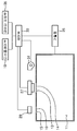
- Figure 2 is a schematic view showing a first embodiment of the present invention.
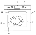
- FIG. 3 is a perspective view showing a second embodiment of a cooking appliance according to the present invention.
- Figure 4 is a block diagram showing a state in which a third embodiment of the cooking appliance according to the present invention connected to the network.
- FIG. 1 is a perspective view showing a first embodiment of a cooking appliance according to the present invention
- Figure 2 is a schematic view showing a first embodiment of the present invention.
- the cooking chamber 11 is provided inside the main body 10 of the cooking appliance.
- the cooking chamber 11 is a place where food is cooked.
- a sensing opening 13 is formed at one side of the upper surface of the cooking chamber 11. Then, the sensing opening 13 is provided with a shielding glass 14. The position of the sensing opening 13 is not limited to the upper surface of the cooking chamber 11. For example, the sensing opening 13 may be formed on any one surface or the rear surface of both sides of the cooking chamber 11. In addition, an illumination opening 15 is formed at one side of the upper surface of the cooking chamber 11.
- an illumination opening 15 is formed at one side of the upper surface of the cooking chamber 11.
- Shielding glass 16 is also installed in the lighting opening 15.
- the lighting opening 15 is formed on one side of the upper surface of the cooking chamber 11 adjacent to the sensing opening 13, but the position of the lighting opening 15 is not limited thereto.
- an input unit 17 and a display unit 19 are provided on an upper portion of the front surface of the main body 10 corresponding to the upper side of the cooking chamber 11.
- the input unit 17 receives an operation signal for the operation of the cooking appliance.
- the display unit 19 serves to display the internal state of the cooking chamber 11 sensed by the image sensor 27 to be described later to the outside.
- the input unit 17 and the display unit 19 are provided above the front surface of the main body 10, but are not necessarily limited thereto.
- the input unit 17 and the display unit 19 may be provided on the front left and right sides of the main body 10.
- the cooking chamber 11 is selectively opened and closed by the door 20.
- the front end of the door 20 is rotated forward and backward of the main body 10 about its vertical axis.
- the door 20 is provided with a see-through window 21.
- the viewing window 21 is for the user to directly identify the internal state of the cooking chamber 11 with the naked eye.
- the viewing portion 21 may be formed by forming a central portion of the door 20 into a transparent or translucent material.
- the front of the front of the door 20, the door handle 23 is held by the user to open and close the door 20 is provided.
- the heating source 25 is installed inside the main body 10.
- the heating source 25 serves to heat the food inside the cooking chamber 11.
- the image sensor 27 is installed inside the main body 10.
- the image sensor 27 scans the food housed inside the cooking chamber 11, more specifically, inside the cooking chamber 11.
- the image sensor 27 is above the cooking chamber 11, more specifically, the main body 10 corresponding to the upper side of the sensing opening 13 in which the shielding glass 14 is installed. It is installed at the top of the.
- the lamp 29 is installed inside the main body 10.
- the lamp 29 serves to illuminate the inside of the cooking chamber 11.
- the lamp 29 is located above the lighting opening 15.
- the cooling fan 31 is installed inside the main body 10 adjacent to the image sensor 27.
- the cooling fan 31 generates a flow of air for cooling the image sensor 27.
- the cooling fan 31 is provided separately for cooling the image sensor 27, but the cooling of the image sensor 27 is a cooling fan (not shown) for cooling the heating source 25. It may be made by).
- the controller 33 controls the operations of the heating source 25, the image sensor 27, and the display unit 19. More specifically, the controller 33 controls the heating source 25 to operate according to the operation signal input by the input unit 17.
- the controller 33 controls the scan of the food by the image sensor 27 and the display of an image of the food scanned by the image sensor 27 by the display unit 19. At this time, the control unit 33, the operation of the image sensor 27 is started before the operation of the heating source 25 is started, the image sensor 27 scans the food in real time, the heating source When the operation of 25 ends, the operation of the image sensor 27 is terminated.
- the controller 33 controls the display unit 19 to operate when the image sensor 27 operates.
- the control unit 33 controls the operation of the heating source 25 by determining the cooking degree of the food and whether the cooking is completed in the image of the food scanned by the image sensor 27.
- the control unit 33 reads the RGB color value of the food from the image of the food scanned by the image sensor 27, and the rate of change of the read RGB color value of the food over time. Determine the cooking degree of the food according to.
- the control unit 33 controls the output of the heating source 25 by comparing the change rate of the RGB color value of the read-out food with a preset change rate of the reference RGB color value. For example, the control unit 33 controls the output of the heating source 25 to be increased when the rate of change of the RGB color value of the read out food is less than the reference RGB color value change rate, and the read of the cooked food.
- the rate of change of the RGB color value exceeds the reference RGB color value change rate, the output of the heating source 25 is controlled to be reduced.
- the controller 33 determines that cooking of the food is completed when the RGB color value of the read-out food reaches a predetermined complete RGB color value. Accordingly, the control unit 33 controls the operation of the heating source 25 to stop when the RGB color value of the read-out food reaches the completed RGB color value.
- the reference RGB color value change rate and the complete RGB color value correspond to the rate of change of the RGB color value of the food with the passage of time in the cooking process of the food according to the type of food, and the cooking in a state where cooking of the food is completed. It means the RGB color value of water.
- the RGB color value of water For example, in the case where the food is meat, before the operation of the heating source 25 is started, that is, before cooking, the RGB source value is relatively high, but the heating source 25 is represented.
- the RGB color value of the meat will represent a RGB color value having a relatively high Y ratio. In the process of cooking by the operation of the heating source 25, the RGB color value of the meat will decrease the ratio of R value and increase the ratio of Y value.
- the controller 33 controls the operations of the lamp 29 and the cooling fan 31.
- the control section 33 starts the operation of the lamp 29 and the cooling fan 31 before the operation of the image sensor 27 is started or at the same time as the start of the operation. Control to end at the same time as the end of the operation of (27) or after the end of the operation.
- the reference RGB color value change rate and the completed RGB color value are stored in the data storage 35.
- the reference RGB color value change rate and the completed RGB color value are stored in the data storage unit 35 according to the type of food.
- the user rotates the door 20 in a state in which food is stored in the cooking chamber 11 to shield the cooking chamber 11.
- the controller 33 controls the heating source 25 to operate. Therefore, the cooking of the food in the cooking chamber 11 is performed.
- the controller 33 allows the operation of the image sensor 27 and the lamp 29 to be started before the operation of the heating source 25 is started. Accordingly, the inside of the cooking chamber 11 is scanned in real time by the image sensor 27, and the image of the food scanned by the image sensor 27 is displayed to the outside through the display unit 19. In addition, the controller 33 controls the operation of the cooling fan 31 to start the cooling of the image sensor 27.
- control unit 33 reads the RGB color value of the food from the image of the food scanned by the image sensor 27, compares the change rate over time with the reference RGB color value change rate, and The output of the heating source 25 is controlled to be maintained, increased or decreased.
- the control unit 33 determines whether the RGB color value of the read-out food has reached the completed RGB color value. If it is determined that the RGB color value of the read-out food has reached the completed RGB color value, the control unit 33 controls the operation of the heating source 25 to end. When the operation of the heating source 25 is terminated, the controller 33 controls the operation of the image sensor 27, the lamp 29, and the cooling fan 31 to end.
- the controller 33 controls the image of the food scanned by the image sensor 27 to be displayed on the display unit 19. Therefore, the user can more easily determine the cooking degree and the cooking completion of the food inside the cooking chamber 11 from the image of the food displayed on the display unit 19.
- FIGS. 1 and 2 are perspective views showing a second embodiment of a cooking appliance according to the present invention.
- the same components as those of the first embodiment of the present invention described above among the components of the present embodiment will be omitted by using the reference numerals of FIGS. 1 and 2.
- the door 20 is provided with an image display unit 37 for displaying an image of a food scanned by the image sensor 27. More specifically, the image display unit 37 is located at the center of the door 20 corresponding to the see-through window 21 (see FIG. 1) of the first embodiment described above. Therefore, the image display unit 37 of the present embodiment may be formed relatively larger than the display unit 19 (see FIG. 1) of the first embodiment described above.
- dew is formed on the viewing window 21 during the cooking process of the food in the cooking chamber 11 to substantially prevent a phenomenon in which the identification of the food through the viewing window 21 is not accurately made.
- FIGS. 4 is a configuration diagram showing a third embodiment of a cooking appliance according to the present invention connected to a network.
- the same components as those of the first embodiment of the present invention described above among the components of the present embodiment will be omitted by using the reference numerals of FIGS. 1 and 2.
- the cooking apparatus in the cooking apparatus according to the present embodiment, cooking of the food by the heating source 25 is performed inside the cooking chamber 11.
- the image sensor 27 scans the food inside the cooking chamber 11 to form an image of the food, and the display unit 19 displays the image of the food scanned by the image sensor 27.
- the control unit 33 controls the operations of the image sensor 27 and the display unit 19.
- the data storage unit 35 stores the reference RGB color value change rate and the completed RGB color value according to the type of food.
- the data storage unit 35 may store a recipe and a character image transmitted to the terminal 43 to be described later.
- the character image may change according to the cooking process of the food inside the cooking chamber 11.
- the cooking appliance according to the present embodiment further includes a communication unit 39 for communication with the terminal through the network 41.
- the communication unit 39 of the cooking appliance transmits information including the image of the food scanned by the image sensor 27 to the terminal 43 through the network 41, and from the terminal 43. Receives the information and delivers it to the controller 33.
- the network 41 connects the communication unit 39 and the terminal 43 of the cooking appliance.
- the network 41 may connect the communication unit 39 and the terminal 43 by wire or wirelessly.
- the terminal 43 transmits and receives data to and from the cooking apparatus at a remote location spaced apart from the cooking apparatus through the network 41.
- the cooking apparatus transmits an image of the food scanned by the image sensor 27 to the terminal 43.
- the terminal 43 transmits an operation signal for controlling the operation of the cooking appliance, more specifically, the operation of the heating source 25 to the cooking appliance.
- the cooking apparatus transmits data stored in the data storage unit 35, that is, a recipe and a character image, to the terminal 43.
- the controller 33 reads an RGB color value from the image of the food scanned by the image sensor 27 to determine the type of food, and the terminal 43 from the cooking appliance according to the determined food type. Recipes and character images are controlled to be sent.
- the controller 33 determines the type of food stored in the cooking chamber 11 from the RGB color value of the read-out food, and the recipe and character image corresponding to the determined food type are determined. Control to be transmitted to the terminal 43.
- the terminal 43 is provided with a communication unit 39 for communication with the cooking appliance in order to transmit and receive data between the cooking appliance and the terminal 43.
- the terminal 43 is provided with a display unit 19 for displaying an image of the food and an input unit 17 for inputting an operation signal.
- a separate terminal 19 or an input unit 17 for displaying a computer, a mobile phone, or an image of the food may be used.
Landscapes
- Engineering & Computer Science (AREA)
- Chemical & Material Sciences (AREA)
- Combustion & Propulsion (AREA)
- Mechanical Engineering (AREA)
- General Engineering & Computer Science (AREA)
- Physics & Mathematics (AREA)
- Electromagnetism (AREA)
- Electric Ovens (AREA)
- Electric Stoves And Ranges (AREA)
Abstract
본 발명은 조리기기에 관한 것이다. 본 발명에서는, 이미지센서가 스캔한 조리실의 내부의 이미지를 디스플레이부를 통하여 외부로 표시한다. 따라서 본 발명에 의하면, 사용자가 보다 정확한 조리실의 내부상태를 보다 용이하게 인식할 수 있는 이점이 있다.
Description
본 발명은 조리기기에 관한 것으로, 보다 상세하게는 조리물의 이미지를 스캔하여 표시하는 조리기기 및 그 제어방법에 관한 것이다.
조리기기란, 전기나 가스를 사용하여 조리물을 조리하는 가전기기이다. 이와 같은 조리기기에는, 조리실의 내부의 조리물을 가열하기 위한 가열원이 구비된다. 한편 상기 조리기기에는, 상기 조리실의 온도나 습도를 감지하기 위한 온도센서나 습도센서 등이 구비된다. 그리고 상기 온도센서나 습도센서가 감지한 상기 조리실의 온도 및 습도에 따라서 상기 가열원의 동작을 제어하여 상기 조리실에서의 조리물의 조리가 원활하게 이루어진다.
본 발명의 목적은, 조리실의 내부상태를 보다 정확하게 감지할 수 있는 조리기기 및 그 제어방법을 제공하는 것이다.
본 발명의 다른 목적은, 조리실의 내부상태를 사용자가 보다 용이하게 인식할 수 있는 조리기기 및 그 제어방법을 제공하는 것이다.
본 발명의 실시예에 의한 조리기기는, 조리물이 조리되는 조리실이 구비되는 본체; 상기 조리실을 선택적으로 개폐하는 도어; 상기 조리실에서의 조리물의 가열을 위한 열을 제공하는 가열원; 상기 조리실의 내부의 조리물을 스캔하는 이미지센서; 상기 이미지센서가 스캔한 상기 조리물의 이미지를 표시하는 디스플레이부; 및 상기 이미지센서가 스캔한 상기 조리물의 이미지로부터 조리물의 조리정도 및 조리완료여부를 판단하여 상기 가열원의 동작을 제어하는 제어부; 를 포함
본 발명의 다른 실시예에 의한 조리기기는, 조리물이 조리되는 조리실이 구비되는 본체; 상기 조리실을 선택적으로 개폐하는 도어; 상기 조리실에서의 조리물의 가열을 위한 열을 제공하는 가열원; 상기 조리실의 내부의 조리물을 스캔하는 이미지센서; 상기 이미지센서가 스캔한 상기 조리물의 이미지를 표시하는 디스플레이부; 외부의 단말과의 데이터의 송수신을 위한 통신부; 조리물의 종류에 따른 데이터가 저장되는 데이터저장부; 및 상기 이미지센서가 스캔한 상기 조리물의 이미지로부터 상기 조리실에서 조리되는 조리물의 종류를 판단하고, 판단된 조리물의 종류에 따라서 상기 데이터저장부에 저장된 데이터 중 조리물에 대응하는 데이터가 상기 통신부에 의하여 상기 단말로 송신되도록 제어한다.
본 발명의 실시예에 의한 조리기기 제어방법은, 이미지센서가, 조리물의 이미지를 스캔하는 단계; 가열원이, 상기 조리물의 가열을 위하여 열을 제공하는 단계; 제어부가, 상기 이미지센서가 스캔한 상기 조리물의 이미지로부터 상기 가열원에 의하여 가열되어 변화되는 상기 조리물의 RGB색상값을 독출하는 단계; 상기 제어부가, 독출된 상기 조리물의 RGB색상값의 시간의 경과에 따른 변화율에 따라서 조리물의 조리정도를 판단하는 단계; 및 상기 제어부가, 판단된 조리물의 조리정도에 따라서 상기 가열원의 동작을 제어하는 단계; 를 포함한다.
본 발명의 다른 실시예에 의한 조리기기 제어방법은, 이미지센서가, 조리실의 내부의 조리물의 이미지를 스캔하는 이미지 스캔단계; 가열원이, 상기 조리물의 가열을 위하여 열을 제공하는 가열단계; 제어부가, 상기 이미지센서가 스캔한 상기 조리물의 이미지로부터 상기 가열원에 의하여 가열되어 변화되는 상기 조리물의 RGB색상값을 독출하는 RGB색상값 독출단계; 상기 제어부가, 독출된 상기 조리물의 RGB색상값의 시간의 경과에 따른 변화율을 기설정된 기준RGB색상값변화율 및 완료RGB색상값변화율과 비교하여 조리물의 조리정도 및 조리완료 여부를 판단하는 조리정도 판단단계; 및 상기 제어부가, 판단된 조리물의 조리정도 및 조리완료 여부에 따라서 상기 가열원의 동작을 제어하는 가열원 제어단계; 를 포함한다.
이상에서 설명한 바와 같은 본 발명에 의한 조리기기 및 그 제어방법에 의하면, 다음과 같은 효과를 기대할 수 있게 된다.
먼저 본 발명에서는, 이미지센서에 의하여 스캔된 조리물의 이미지가 외부로 표시된다. 따라서 사용자가 상기 조리물의 상태를 보다 정확하게 인식할 수 있게 된다.
또한 본 발명에서는, 상기 이미지센서에 의하여 스캔된 상기 조리물의 이미지를 조리기기로부터 이격된 장소에 위치하는 사용자에게 무선 또는 유선통신으로 전송된다. 따라서 사용자가 상기 조리물의 상태를 보다 용이하게 인식할 수 있게 된다.
뿐만 아니라, 본 발명에서는, 상기 이미지센서에 의하여 스캔된 상기 조리물의 이미지를 표시하는 디스플레이부가 상기 조리실을 선택적으로 개폐하는 도어의 전면에 표시된다. 따라서 상기 디스플레이부의 위치 설계가 보다 용이하게 이루어질 수 있게 된다.
도 1은 본 발명에 의한 조리기기의 제1실시예를 보인 사시도.
도 2는 본 발명의 제1실시예를 개략적으로 보인 구성도.
도 3은 본 발명에 의한 조리기기의 제2실시예를 보인 사시도.
도 4는 본 발명에 의한 조리기기의 제3실시예가 네트워크에 연결된 상태를 보인 구성도.
이하에서는 본 발명에 의한 조리기기의 제1실시예의 구성을 첨부된 도면을 참조하여 보다 상세하게 설명한다.
도 1은 본 발명에 의한 조리기기의 제1실시예를 보인 사시도이고, 도 2는 본 발명의 제1실시예를 개략적으로 보인 구성도이다.
도 1 및 도 2를 참조하면, 조리기기의 본체(10)의 내부에는 조리실(11)이 구비된다. 상기 조리실(11)은 조리물의 조리가 이루어지는 곳이다.
상기 조리실(11)의 상면 일측에 센싱개구(13)가 형성된다. 그리고 상기 센싱개구(13)에는 차폐글래스(14)가 설치된다. 상기 센싱개구(13)의 위치는 상기 조리실(11)의 상면에 한정되지 않는다. 예를 들면, 상기 센싱개구(13)는, 상기 조리실(11)의 양측면 중 어느 일면이나 후면에 형성될 수 있다. 또한 상기 조리실(11)의 상면 일측에는 조명개구(15)가 형성된다.
또한 상기 조리실(11)의 상면 일측에는 조명개구(15)가 형성된다. 상기 조명개구(15)에도 차폐글래스(16)가 설치된다. 본 실시예에서는, 상기 조명개구(15)가 상기 센싱개구(13)에 인접하는 상기 조리실(11)의 상면 일측에 형성되지만, 상기 조명개구(15)의 위치가 이에 한정되는 것은 아니다.
그리고 상기 조리실(11)의 상방에 해당하는 상기 본체(10)의 전면 상부에는 입력부(17) 및 디스플레이부(19)가 구비된다. 상기 입력부(17)는 상기 조리기기의 동작을 위한 조작신호를 입력받는다. 상기 디스플레이부(19)는, 후술할 이미지센서(27)가 감지한 상기 조리실(11)의 내부상태를 외부로 표시하는 역할을 한다. 본 실시예에서는, 상기 입력부(17) 및 디스플레이부(19)가 상기 본체(10)의 전면 상부에 구비되지만, 반드시 이에 한정되는 것은 아니다. 예를 들면, 상기 입력부(17) 및 디스플레이부(19)는, 상기 본체(10)의 전면 좌우측에 구비될 수도 있다.
한편 상기 조리실(11)은 도어(20)에 의하여 선택적으로 개폐된다. 상기 도어(20)는 그 수직방향의 축을 중심으로 그 선단이 상기 본체(10)의 전후방으로 회전한다. 상기 도어(20)에는 투시창(21)이 구비된다. 상기 투시창(21)은, 상기 조리실(11)의 내부상태를 사용자가 육안으로 직접 식별하기 위한 것이다. 예를 들면, 상기 도어(20)의 중앙부가 투명 또는 반투명재질로 성형되어 상기 투시창(21)이 형성될 수 있다. 또한 상기 도어(20)의 전면 상단에는, 상기 도어(20)를 여닫기 위하여 사용자가 파지하는 도어핸들(23)이 구비된다.
상기 본체(10)의 내부에는 가열원(25)이 설치된다. 상기 가열원(25)은, 상기 조리실(11)의 내부의 조리물을 가열하는 역할을 한다. 예를 들면, 상기 가열원(25)으로는, 상기 조리실(11)의 내부로 마이크로웨이브를 조사하는 고주파가열원이나 상기 조리실(11)의 내부로 복사열이나 대류열을 공급하는 복사가열원 또는 대류가열원 중 어느 하나 이상이 사용될 수 있다.
또한 상기 본체(10)의 내부에는 이미지센서(27)가 설치된다. 상기 이미지센서(27)는, 상기 조리실(11)의 내부, 보다 상세하게는, 상기 조리실(11)의 내부에 수납된 조리물을 스캔한다. 본 실시예에서는, 상기 이미지센서(27)가 상기 조리실(11)의 상방, 보다 상세하게는, 상기 차폐글래스(14)가 설치되는 상기 센싱개구(13)의 상방에 해당하는 상기 본체(10)의 상부에 설치된다.
또한 상기 본체(10)의 내부에는 램프(29)가 설치된다. 상기 램프(29)는 상기 조리실(11)의 내부를 조명하는 역할을 한다. 상기 램프(29)는 상기 조명개구(15)의 상방에 위치된다.
그리고 상기 이미지센서(27)에 인접하는 상기 본체(10)의 내부에는 냉각팬(31)이 설치된다. 상기 냉각팬(31)은 상기 이미지센서(27)의 냉각을 위한 공기의 흐름을 발생시킨다. 본 실시예에서는, 상기 냉각팬(31)이 상기 이미지센서(27)의 냉각을 위하여 별도로 구비되지만, 상기 이미지센서(27)의 냉각은 상기 가열원(25)의 냉각을 위한 냉각팬(미도시)에 의하여 이루어질 수도 있다.
상기 가열원(25), 이미지센서(27) 및 디스플레이부(19)의 동작을 제어부(33)가 제어한다. 보다 상세하게는, 상기 제어부(33)는, 상기 입력부(17)가 입력받은 조작신호에 따라서 상기 가열원(25)이 동작되도록 제어한다. 그리고 상기 제어부(33)는 상기 이미지센서(27)에 의한 상기 조리물의 스캔 및 상기 디스플레이부(19)에 의한 상기 이미지센서(27)가 스캔한 상기 조리물의 이미지의 표시를 제어하는 역할을 한다. 이때 상기 제어부(33)는, 상기 가열원(25)의 동작이 개시되기 전 상기 이미지센서(27)의 동작이 개시되어 상기 이미지센서(27)가 상기 조리물을 실시간으로 스캔하고, 상기 가열원(25)의 동작이 종료되면 상기 이미지센서(27)의 동작이 종료되도록 제어한다. 또한 상기 제어부(33)는 상기 이미지센서(27)의 동작하면 상기 디스플레이부(19)도 동작되도록 제어한다. 따라서 상기 디스플레이부(19)의 동작은, 상기 이미지센서(27)의 동작의 개시와 동시에 개시되고, 상기 이미지센서(27)의 동작의 종료와 동시에 종료될 것이다. 그리고 상기 제어부(33)는, 상기 이미지센서(27)가 스캔한 상기 조리물의 이미지에서 조리물의 조리정도 및 조리의 완료여부를 판단하여 상기 가열원(25)의 동작의 동작을 제어한다.
본 실시예에서는, 상기 제어부(33)는, 상기 이미지센서(27)가 스캔한 상기 조리물의 이미지로부터 조리물의 RGB색상값을 독출하고, 독출된 상기 조리물의 RGB색상값의 시간의 경과에 따른 변화율에 따라서 조리물의 조리정도를 판단한다. 이때 상기 제어부(33)는, 독출된 상기 조리물의 RGB색상값의 변화율과 기설정된 기준RGB색상값변화율을 비교하여 상기 가열원(25)의 출력을 제어한다. 예를 들면, 상기 제어부(33)는, 독출된 상기 조리물의 RGB색상값의 변화율이 상기 기준RGB색상값변화율 미만인 경우에는 상기 가열원(25)의 출력이 증가되도록 제어하고, 독출된 상기 조리물의 RGB색상값의 변화율이 상기 기준RGB색상값변화율 초과인 경우에는 상기 가열원(25)의 출력이 감소되도록 제어한다.
또한 상기 제어부(33)는, 독출된 상기 조리물의 RGB색상값이 기설정된 완료RGB색상값에 도달하면, 조리물의 조리가 완료된 것으로 판단한다. 따라서 상기 제어부(33)는 독출된 상기 조리물의 RGB색상값이 상기 완료RGB색상값에 도달하면, 상기 가열원(25)의 동작이 정지되도록 제어한다.
*여기서 상기 기준RGB색상값변화율 및 완료RGB색상값은, 조리물의 종류에 따라서 조리물의 조리과정에서의 시간의 경과에 따른 상기 조리물의 RGB색상값의 변화율 및 조리물의 조리가 완료된 상태에서의 상기 조리물의 RGB색상값을 의미한다. 예를 들면, 조리물이 육류의 경우에는, 상기 가열원(25)의 동작이 개시되기 전, 즉 조리되기 전에는, 상대적으로 R의 비율이 높은 RGB색상값을 나타내지만, 상기 가열원(25)의 동작에 의하여 육류가 조리되어 익기 시작하면, 육류의 RGB색상값은 상대적으로 Y의 비율이 높은 RGB색상값을 나타낼 것이다. 그리고 상기 가열원(25)의 동작에 의하여 조리되는 과정에서는, 육류의 RGB색상값은 R값이 비율은 저하되고 Y값의 비율은 증가될 것이다.
상기 제어부(33)는, 상기 램프(29) 및 냉각팬(31)의 동작을 제어한다. 본 실시예에서는, 상기 제어부(33)가, 상기 이미지센서(27)의 동작이 개시되기 전 또는 동작의 개시와 동시에 상기 램프(29) 및 냉각팬(31)의 동작이 개시되고, 상기 이미지센서(27)의 동작의 종료와 동시 또는 동작의 종료 후에 종료되도록 제어한다.
그리고 상기 기준RGB색상값변화율 및 완료RGB색상값 등은 데이터저장부(35)에 저장된다. 이때 상기 데이터저장부(35)에는, 조리물의 종류에 따라서 상기 기준RGB색상값변화율 및 완료RGB색상값이 저장된다.
이하에서는 본 발명에 의한 조리기기의 제1실시예의 작용을 보다 상세하게 설명한다.
먼저 사용자가 상기 조리실(11)의 내부에 조리물을 수납한 상태에서 상기 도어(20)를 회동시켜서 상기 조리실(11)을 차폐한다. 그리고 사용자가 상기 입력부(17)를 조작하여 조리물의 조리를 위한 조작신호를 입력하면, 상기 제어부(33)는 상기 가열원(25)이 동작되도록 제어한다. 따라서 상기 조리실(11)에서의 조리물의 조리가 이루어진다.
한편 상기 제어부(33)는, 상기 가열원(25)의 동작이 개시되기 전에 상기 이미지센서(27) 및 램프(29)의 동작이 개시되도록 한다. 따라서 상기 이미지센서(27)에 의하여 상기 조리실(11)의 내부가 실시간으로 스캔되고, 상기 이미지센서(27)에 의하여 스캔된 상기 조리물의 이미지는 상기 디스플레이부(19)를 통하여 외부로 표시된다. 또한 상기 제어부(33)는, 상기 이미지센서(27)의 냉각을 위하여 상기 냉각팬(31)의 동작이 개시되도록 제어한다.
이때 상기 제어부(33)는, 상기 이미지센서(27)가 스캔한 상기 조리물의 이미지로부터 조리물의 RGB색상값을 독출하여, 그 시간의 경과에 따른 변화율과 상기 기준RGB색상값변화율을 비교하여, 상기 가열원(25)의 출력이 유지, 증가 또는 감소되도록 제어한다.
그리고 상기 제어부(33)는, 독출된 상기 조리물의 RGB색상값이 상기 완료RGB색상값에 도달하였는지 여부를 판단한다. 그리고 상기 제어부(33)는, 독출된 상기 조리물의 RGB색상값이 상기 완료RGB색상값에 도달한 것으로 판단되면, 상기 가열원(25)의 동작이 종료되도록 제어한다. 상기 제어부(33)는 상기 가열원(25)의 동작이 종료되면, 상기 이미지센서(27), 램프(29) 및 냉각팬(31)의 동작이 종료되도록 제어한다.
한편 상기 제어부(33)는 상기 이미지센서(27)가 스캔한 상기 조리물의 이미지가 상기 디스플레이부(19)를 통하여 표시되도록 제어한다. 따라서 사용자는, 상기 디스플레이부(19)에 표시된 상기 조리물의 이미지로부터 상기 조리실(11)의 내부에서의 조리물의 조리정도 및 조리완료여부를 보다 용이하게 판단할 수 있게 된다.
이하에서는 본 발명에 의한 조리기기의 제2실시예의 구성을 첨부된 도면을 참조하여 보다 상세하게 설명한다.
도 3은 본 발명에 의한 조리기기의 제2실시예를 보인 사시도이다. 본 실시예의 구성요소 중 상술한 본 발명의 제1실시예의 구성요소와 동일한 구성요소에 대해서는 도 1 및 도 2의 도면부호를 원용하여 상세한 설명을 생략하기로 한다.
도 3을 참조하면, 본 실시예에서는, 이미지센서(27)가 스캔한 조리물의 이미지를 표시하기 위한 이미지디스플레이부(37)가 도어(20)에 구비된다. 보다 상세하게는, 상기 이미지디스플레이부(37)는, 상술한 제1실시예의 투시창(21)(도 1참조)에 대응하는 상기 도어(20)의 중앙부에 위치된다. 따라서 본 실시예의 이미지디스플레이부(37)는, 상술한 제1실시예의 디스플레이부(19)(도 1참조)에 비하여 상대적으로 크게 형성될 수 있다.
이는 사용자가, 상기 이미지센서(27)(도 2참조)에 의하여 스캔된 조리물의 이미지를 보다 크게 볼 수 있도록 하기 위함이다. 또한 상기 조리실(11)에서의 조리물의 조리과정에서 상기 투시창(21)에 이슬이 맺힘으로써, 실질적으로 상기 투시창(21)을 통한 조리물의 식별이 정확하게 이루어지지 않는 현상을 방지하기 위함이다.
이하에서는 본 발명에 의한 조리기기의 제4실시예의 구성을 첨부된 도면을 참조하여 보다 상세하게 설명한다.
도 4는 본 발명에 의한 조리기기의 제3실시예가 네트워크에 연결된 상태를 보인 구성도이다. 본 실시예의 구성요소 중 상술한 본 발명의 제1실시예의 구성요소와 동일한 구성요소에 대해서는 도 1 및 도 2의 도면부호를 원용하여 상세한 설명을 생략하기로 한다.
도 4를 참조하면, 본 실시예에 의한 조리기기에서는, 조리실(11)의 내부에서 가열원(25)에 의한 조리물의 조리가 이루어진다. 그리고 이미지센서(27)가 조리실(11)의 내부의 조리물을 스캔하여 조리물의 이미지를 형성하고, 디스플레이부(19)가 상기 이미지센서(27)가 스캔한 상기 조리물의 이미지를 표시한다. 그리고 제어부(33)는, 상기 이미지센서(27) 및 디스플레이부(19)의 동작을 제어한다.
또한 데이터저장부(35)에는 조리물의 종류에 따라서 기준RGB색상값변화율 및 완료RGB색상값이 저장된다. 또한 본 실시예에서는, 상기 데이터저장부(35)에는, 후술할 단말(43)로 전송되는 요리법 및 캐릭터이미지가 저장될 수 있다. 이때 상기 캐릭터이미지는, 상기 조리실(11)의 내부에서의 조리물의 조리과정에 따라서 변할 수 있다.
한편 본 실시예에 의한 조리기기는, 네트워크(41)를 통한 단말과의 통신을 위한 통신부(39)를 더 포함한다. 상기 조리기기의 통신부(39)는, 상기 네트워크(41)를 통하여 상기 단말(43)로 상기 이미지센서(27)가 스캔한 상기 조리물의 이미지를 포함하는 정보를 송신하고, 상기 단말(43)로부터 정보를 수신하여 상기 제어부(33)에 전달한다.
상기 네트워크(41)는, 상기 조리기기의 통신부(39) 및 단말(43)을 연결한다. 상기 네트워크(41)는 유선 또는 무선으로 상기 통신부(39) 및 단말(43)을 연결할 수 있다. 상기 단말(43)은, 상기 네트워크(41)를 통하여 조리기기로부터 이격된 원격지에서 상기 조리기기와 데이터를 송수신한다.
예를 들면, 상기 조리기기는, 상기 이미지센서(27)가 스캔한 상기 조리물의 이미지를 상기 단말(43)로 송신한다. 또한 상기 단말(43)는, 상기 조리기기의 동작, 보다 상세하게는, 상기 가열원(25)의 동작을 제어하기 위한 조작신호를 상기 조리기기로 송신한다. 또한 상기 조리기기는, 상기 데이터저장부(35)에 저장된 데이터, 즉 요리법 및 캐릭터이미지를 상기 단말(43)로 송신한다. 이때 상기 제어부(33)는, 상기 이미지센서(27)가 스캔한 상기 조리물의 이미지로부터 RGB색상값을 독출하여 조리물의 종류를 판단하고, 판단한 조리물의 종류에 따라서 상기 조리기기로부터 상기 단말(43)로 요리법 및 캐릭터이미지가 송신되도록 제어한다. 다시 말하면, 상기 제어부(33)는, 독출된 상기 조리물의 RGB색상값으로부터 상기 조리실(11)의 내부에 수납된 조리물을 종류를 판단하고, 판단된 조리물의 종류에 대응하는 요리법 및 캐릭터이미지가 상기 단말(43)로 송신되도록 제어하는 것이다.
한편 상기 조리기기와 단말(43)의 데이터의 송수신을 위하여 상기 단말(43)에는 상기 조리기기와의 통신을 위한 통신부(39)가 구비된다. 또한 상기 단말(43)에는, 상기 조리물의 이미지를 표시하기 위한 디스플레이부(19) 및 조작신호를 입력하기 위한 입력부(17)가 구비된다. 상기 단말(43)로는, 컴퓨터나 휴대폰, 또는 상기 조리물의 이미지를 표시하기 위한 별도의 디스플레이부(19)나 입력부(17)가 별개의 단말이 사용될 수 있다.
이와 같은 본 발명의 기본적인 기술적 사상의 범주 내에서, 당업계의 통상의 지식을 가진 자에게 있어서는 다른 많은 변형이 가능함은 물론이고, 본 발명의 권리범위는 첨부한 특허청구범위에 기초하여 해석되어야 할 것이다.
Claims (19)
- 조리물이 조리되는 조리실이 구비되는 본체;상기 조리실을 선택적으로 개폐하는 도어;상기 조리실에서의 조리물의 가열을 위한 열을 제공하는 가열원;상기 조리실의 내부의 조리물을 스캔하는 이미지센서;상기 이미지센서가 스캔한 상기 조리물의 이미지를 표시하는 디스플레이부; 및상기 이미지센서가 스캔한 상기 조리물의 이미지로부터 조리물의 조리정도 및 조리완료여부를 판단하여 상기 가열원의 동작을 제어하는 제어부; 를 포함하는 조리기기.
- 제 1 항에 있어서,상기 제어부는, 상기 이미지센서가 스캔한 상기 조리물의 이미지로부터 조리물의 RGB색상값을 독출하고, 독출된 상기 조리물의 RGB색상값의 시간의 경과에 따른 변화율에 따라서 조리물의 조리정도를 판단하는 조리기기.
- 제 2 항에 있어서,상기 제어부는, 독출된 상기 조리물의 RGB색상값의 변화율이 기설정된 기준RGB색상값변화율 미만인 경우에는, 상기 가열원에 의하여 상기 조리실의 내부로 제공되는 열이 증가되도록 제어하고, 독출된 상기 조리물의 RGB색상값의 변화율이 상기 기준RGB색상값변화율 초과인 경우에는 상기 가열원에 의하여 상기 조리실의 내부로 제공되는 열이 감소되도록 제어하는 조리기기.
- 제 2 항에 있어서,상기 제어부는, 독출된 상기 조리물의 RGB색상값이 기설정된 완료RGB색상값에 도달하면, 상기 가열원의 동작이 정지되도록 제어하는 조리기기.
- 제 1 항에 있어서,외부의 단말과의 데이터의 송수신을 위한 통신부를 더 포함하는 조리기기.
- 제 5 항에 있어서,상기 통신부에 의하여 상기 단말로 송신하는 데이터는, 적어도 상기 이미지센서가 스캔한 상기 조리물의 이미지를 포함하는 조리기기.
- 제 5 항에 있어서,상기 통신부에 의하여 상기 단말로부터 수신되는 데이터는, 적어도 상기 가열원의 동작을 제어하는 조작신호를 포함하는 조리기기.
- 조리물이 조리되는 조리실이 구비되는 본체;상기 조리실을 선택적으로 개폐하는 도어;상기 조리실에서의 조리물의 가열을 위한 열을 제공하는 가열원;상기 조리실의 내부의 조리물을 스캔하는 이미지센서;상기 이미지센서가 스캔한 상기 조리물의 이미지를 표시하는 디스플레이부;외부의 단말과의 데이터의 송수신을 위한 통신부;조리물의 종류에 따른 데이터가 저장되는 데이터저장부; 및상기 이미지센서가 스캔한 상기 조리물의 이미지로부터 상기 조리실에서 조리되는 조리물의 종류를 판단하고, 판단된 조리물의 종류에 따라서 상기 데이터저장부에 저장된 데이터 중 조리물에 대응하는 데이터가 상기 통신부에 의하여 상기 단말로 송신되도록 제어하는 제어부; 를 포함하는 조리기기.
- 제 8 항에 있어서,상기 제어부는, 상기 이미지센서가 스캔한 상기 조리물의 이미지로부터 조리물의 RGB색상값을 독출하고, 독출된 상기 조리물의 RGB색상값에 따라서 조리물의 종류를 판단하는 조리기기.
- 제 8 항에 있어서,상기 데이터저장부에 저장되는 데이터는, 적어도 조리물의 요리법 및 조리물의 조리과정에 따라서 변하는 캐릭터이미지를 포함하는 조리기기.
- 제 8 항에 있어서,상기 통신부는, 유선 또는 무선네트워크에 의하여 상기 단말에 연결되는 조리기기.
- 이미지센서가, 조리물의 이미지를 스캔하는 단계;가열원이, 상기 조리물의 가열을 위하여 열을 제공하는 단계;제어부가, 상기 이미지센서가 스캔한 상기 조리물의 이미지로부터 상기 가열원에 의하여 가열되어 변화되는 상기 조리물의 RGB색상값을 독출하는 단계;상기 제어부가, 독출된 상기 조리물의 RGB색상값의 시간의 경과에 따른 변화율에 따라서 조리물의 조리정도를 판단하는 단계; 및상기 제어부가, 판단된 조리물의 조리정도에 따라서 상기 가열원의 동작을 제어하는 단계; 를 포함하는 조리기기 제어방법.
- 제 12 항에 있어서,상기 제어부는, 독출된 상기 조리물의 RGB색상값의 변화율이 기설정된 기준RGB색상값변화율 미만인 경우에는, 상기 가열원에 의하여 상기 조리실의 내부로 제공되는 열이 증가되도록 제어하고, 독출된 상기 조리물의 RGB색상값의 변화율이 상기 기준RGB색상값변화율 초과인 경우에는 상기 가열원에 의하여 상기 조리실의 내부로 제공되는 열이 감소되도록 제어하는 조리기기 제어방법.
- 제 12 항에 있어서,상기 제어부는, 독출된 상기 조리물의 RGB색상값이 기설정된 완료RGB색상값에 도달하면, 상기 가열원의 동작이 정지되도록 제어하는 조리기기 제어방법.
- 제 12 항에 있어서,통신부가, 적어도 상기 이미지센서가 스캔한 상기 조리물의 이미지를 포함하는 데이터를 외부의 단말에 송신하는 단계를 더 포함하는 조리기기 제어방법.
- 이미지센서가, 조리실의 내부의 조리물의 이미지를 스캔하는 이미지 스캔단계;가열원이, 상기 조리물의 가열을 위하여 열을 제공하는 가열단계;제어부가, 상기 이미지센서가 스캔한 상기 조리물의 이미지로부터 상기 가열원에 의하여 가열되어 변화되는 상기 조리물의 RGB색상값을 독출하는 RGB색상값 독출단계;상기 제어부가, 독출된 상기 조리물의 RGB색상값의 시간의 경과에 따른 변화율을 기설정된 기준RGB색상값변화율 및 완료RGB색상값변화율과 비교하여 조리물의 조리정도 및 조리완료 여부를 판단하는 조리정도 판단단계; 및상기 제어부가, 판단된 조리물의 조리정도 및 조리완료 여부에 따라서 상기 가열원의 동작을 제어하는 가열원 제어단계; 를 포함하는 조리기기 제어방법.
- 제 16 항에 있어서,상기 제어부는,상기 조리정도 판단단계에서, 독출된 상기 조리물의 RGB색상값의 변화율이 기설정된 기준RGB색상값변화율 미만인 경우에는, 상기 가열원 제어단계에서, 상기 가열원에 의하여 상기 조리실의 내부로 제공되는 열이 증가되도록 제어하고,상기 조리정도 판단단계에서, 독출된 상기 조리물의 RGB색상값의 변화율이 상기 기준RGB색상값변화율 초과인 경우에는, 상기 가열원 제어단계에서, 상기 가열원에 의하여 상기 조리실의 내부로 제공되는 열이 감소되도록 제어하는 조리기기 제어방법.
- 제 16 항에 있어서,상기 제어부는, 상기 조리정도 판단단계에서, 독출된 상기 조리물의 RGB색상값이 기설정된 완료RGB색상값에 도달하면, 상기 가열원 제어단계에서, 상기 가열원의 동작이 정지되도록 제어하는 조리기기 제어방법.
- 제 16 항에 있어서,통신부가, 적어도 상기 이미지센서가 스캔한 상기 조리물의 이미지를 포함하는 데이터를 외부의 단말에 송신하는 데이터 송신단계를 더 포함하는 조리기기 제어방법.
Priority Applications (3)
| Application Number | Priority Date | Filing Date | Title |
|---|---|---|---|
| EP18152931.4A EP3346191B1 (en) | 2009-06-15 | 2010-06-15 | Cooker |
| US13/376,792 US20120076351A1 (en) | 2009-06-15 | 2010-06-15 | Cooker and control method thereof |
| EP10789697.9A EP2444735B1 (en) | 2009-06-15 | 2010-06-15 | Cooker and control method thereof |
Applications Claiming Priority (2)
| Application Number | Priority Date | Filing Date | Title |
|---|---|---|---|
| KR10-2009-0053050 | 2009-06-15 | ||
| KR1020090053050A KR101044143B1 (ko) | 2009-06-15 | 2009-06-15 | 조리기기 |
Publications (2)
| Publication Number | Publication Date |
|---|---|
| WO2010147370A2 true WO2010147370A2 (ko) | 2010-12-23 |
| WO2010147370A3 WO2010147370A3 (ko) | 2011-03-17 |
Family
ID=43356896
Family Applications (1)
| Application Number | Title | Priority Date | Filing Date |
|---|---|---|---|
| PCT/KR2010/003844 WO2010147370A2 (ko) | 2009-06-15 | 2010-06-15 | 조리기기 및 그 제어방법 |
Country Status (4)
| Country | Link |
|---|---|
| US (1) | US20120076351A1 (ko) |
| EP (2) | EP2444735B1 (ko) |
| KR (1) | KR101044143B1 (ko) |
| WO (1) | WO2010147370A2 (ko) |
Families Citing this family (41)
| Publication number | Priority date | Publication date | Assignee | Title |
|---|---|---|---|---|
| KR101909027B1 (ko) * | 2011-08-22 | 2018-10-17 | 엘지전자 주식회사 | 전기제품 정보 관리 시스템 |
| WO2013098004A1 (en) * | 2011-12-26 | 2013-07-04 | Arcelik Anonim Sirketi | Oven with optical detection means |
| EP2662628B1 (en) * | 2012-05-08 | 2019-11-27 | Electrolux Home Products Corporation N.V. | Appliance for processing food and method of operating the same |
| US20140104385A1 (en) * | 2012-10-16 | 2014-04-17 | Sony Network Entertainment International Llc | Method and apparatus for determining information associated with a food product |
| DE102013102295A1 (de) * | 2013-03-07 | 2014-09-11 | Rational Ag | Verfahren zur Anpassung eines Lebensmittel-Garprozesses |
| WO2015185211A2 (en) * | 2014-06-05 | 2015-12-10 | Ingo Stork Genannt Wersborg | Heat treatment monitoring system |
| WO2016128372A1 (en) * | 2015-02-10 | 2016-08-18 | Electrolux Appliances Aktiebolag | Oven door and oven comprising an oven door |
| EP3292738B1 (en) | 2015-05-05 | 2020-12-30 | June Life, Inc. | A connected oven |
| US10739013B2 (en) | 2015-05-05 | 2020-08-11 | June Life, Inc. | Tailored food preparation with an oven |
| WO2016196669A1 (en) * | 2015-06-01 | 2016-12-08 | June Life, Inc. | Thermal management system and method for a connected oven |
| USD787041S1 (en) | 2015-09-17 | 2017-05-16 | Whirlpool Corporation | Gas burner |
| US10837651B2 (en) | 2015-09-24 | 2020-11-17 | Whirlpool Corporation | Oven cavity connector for operating power accessory trays for cooking appliance |
| US20170134652A1 (en) * | 2015-11-06 | 2017-05-11 | L-3 Communications Corporation | Viewport for imaging in an rf/microwave environment |
| US11777190B2 (en) | 2015-12-29 | 2023-10-03 | Whirlpool Corporation | Appliance including an antenna using a portion of appliance as a ground plane |
| US10145568B2 (en) | 2016-06-27 | 2018-12-04 | Whirlpool Corporation | High efficiency high power inner flame burner |
| WO2018044067A1 (en) | 2016-09-01 | 2018-03-08 | Samsung Electronics Co., Ltd. | Oven |
| CN106419498A (zh) * | 2016-10-27 | 2017-02-22 | 广东格兰仕集团有限公司 | 基于图像识别控制火力和时间的烹饪设备及其控制方法 |
| US10551056B2 (en) | 2017-02-23 | 2020-02-04 | Whirlpool Corporation | Burner base |
| US10451290B2 (en) | 2017-03-07 | 2019-10-22 | Whirlpool Corporation | Forced convection steam assembly |
| US10660162B2 (en) | 2017-03-16 | 2020-05-19 | Whirlpool Corporation | Power delivery system for an induction cooktop with multi-output inverters |
| KR102366006B1 (ko) * | 2017-06-20 | 2022-02-23 | 삼성전자주식회사 | 오븐 |
| KR101955876B1 (ko) * | 2017-07-28 | 2019-05-30 | 엘지전자 주식회사 | 오븐 및 그의 제어방법 |
| WO2019075610A1 (en) * | 2017-10-16 | 2019-04-25 | Midea Group Co., Ltd. | CONTROL BY AUTOMATIC LEARNING OF COOKING APPARATUS |
| TR201717330A2 (tr) | 2017-11-06 | 2019-05-21 | Arcelik As | Bi̇r firin ve hari̇ci̇ ci̇haz |
| TR201717412A2 (tr) | 2017-11-07 | 2019-05-21 | Arcelik As | Bi̇r firin |
| CN107908144B (zh) * | 2017-11-24 | 2020-09-18 | 北京小米移动软件有限公司 | 一种控制抽烟机的方法、装置及存储介质 |
| US11116050B1 (en) | 2018-02-08 | 2021-09-07 | June Life, Inc. | High heat in-situ camera systems and operation methods |
| WO2019183342A1 (en) * | 2018-03-21 | 2019-09-26 | Prince Castle LLC | Heat transfer system |
| US10627116B2 (en) | 2018-06-26 | 2020-04-21 | Whirlpool Corporation | Ventilation system for cooking appliance |
| US10619862B2 (en) | 2018-06-28 | 2020-04-14 | Whirlpool Corporation | Frontal cooling towers for a ventilation system of a cooking appliance |
| US10837652B2 (en) | 2018-07-18 | 2020-11-17 | Whirlpool Corporation | Appliance secondary door |
| US20200154943A1 (en) * | 2018-11-16 | 2020-05-21 | GMG Products LLC | Imaging system for cooking device |
| CN109730520B (zh) * | 2018-11-30 | 2021-08-17 | 深圳和而泰智能控制股份有限公司 | 食物加热的控制方法、装置、计算机设备及可读存储介质 |
| US11287140B2 (en) * | 2019-01-04 | 2022-03-29 | Whirlpool Corporation | Cooking appliance with an imaging device |
| US11022322B2 (en) * | 2019-01-04 | 2021-06-01 | Whirlpool Corporation | Cooking appliance with an imaging device |
| WO2021195622A1 (en) | 2020-03-27 | 2021-09-30 | June Life, Inc. | System and method for classification of ambiguous objects |
| BE1028761B1 (de) | 2020-10-29 | 2022-05-31 | Miele & Cie | Verfahren zum Betreiben eines Gargerätes und Gargerät |
| US11940153B2 (en) | 2020-12-01 | 2024-03-26 | GMG Products, LLC | Fuel conditioner for grill |
| DE102020132420A1 (de) | 2020-12-07 | 2022-06-09 | Miele & Cie. Kg | Verfahren zum Betreiben eines Gargeräts und Gargerät |
| US11747087B2 (en) * | 2021-01-06 | 2023-09-05 | Bsh Home Appliances Corporation | Household appliance including reflective door |
| CN113015278A (zh) * | 2021-02-01 | 2021-06-22 | 惠而浦公司 | 用于微波炉中相机窗格玻璃的透明金属涂层 |
Family Cites Families (10)
| Publication number | Priority date | Publication date | Assignee | Title |
|---|---|---|---|---|
| IT1258067B (it) * | 1992-04-02 | 1996-02-20 | Zeltron Spa | Sistema di cottura a controllo automatico |
| JPH0821631A (ja) * | 1994-07-05 | 1996-01-23 | Hitachi Home Tec Ltd | 高周波加熱装置 |
| US6559882B1 (en) * | 1999-09-02 | 2003-05-06 | Ncr Corporation | Domestic appliance |
| JP2001272045A (ja) * | 2000-03-27 | 2001-10-05 | Sanyo Electric Co Ltd | オーブン調理器 |
| EP1382912A1 (en) * | 2001-03-22 | 2004-01-21 | Matsushita Electric Industrial Co., Ltd. | Cooking-related information providing system, cooking-related information providing apparatus, cooking apparatus, cooking-related information providing method, cooking-related information fetch method, cooking-related information providing program, and cooking-related information fetch program |
| KR100605841B1 (ko) * | 2004-06-03 | 2006-08-01 | 삼성전자주식회사 | 엘시디의 회색 준위 상관 색온도 보정장치 및 방법 |
| US20060081135A1 (en) * | 2004-08-16 | 2006-04-20 | Britton Douglas F | Industrial overline imaging system and method |
| US7913615B2 (en) * | 2006-04-28 | 2011-03-29 | Restaurant Technology, Inc. | Automated dual cooking surface grill and method |
| DE102007048834A1 (de) * | 2006-10-17 | 2008-04-24 | BSH Bosch und Siemens Hausgeräte GmbH | Hausgerätevorrichtung mit wenigstens einer Kamera |
| DE102008042804B4 (de) * | 2007-10-16 | 2013-07-04 | BSH Bosch und Siemens Hausgeräte GmbH | Gargerät mit Kamera sowie Verfahren zum Betreiben eines Gargeräts mit Kamera |
-
2009
- 2009-06-15 KR KR1020090053050A patent/KR101044143B1/ko active IP Right Grant
-
2010
- 2010-06-15 EP EP10789697.9A patent/EP2444735B1/en active Active
- 2010-06-15 WO PCT/KR2010/003844 patent/WO2010147370A2/ko active Application Filing
- 2010-06-15 EP EP18152931.4A patent/EP3346191B1/en active Active
- 2010-06-15 US US13/376,792 patent/US20120076351A1/en not_active Abandoned
Non-Patent Citations (1)
| Title |
|---|
| None |
Also Published As
| Publication number | Publication date |
|---|---|
| EP2444735A4 (en) | 2012-11-21 |
| KR101044143B1 (ko) | 2011-06-24 |
| EP3346191B1 (en) | 2020-10-07 |
| KR20100134430A (ko) | 2010-12-23 |
| EP3346191A1 (en) | 2018-07-11 |
| EP2444735B1 (en) | 2018-02-28 |
| EP2444735A2 (en) | 2012-04-25 |
| WO2010147370A3 (ko) | 2011-03-17 |
| US20120076351A1 (en) | 2012-03-29 |
Similar Documents
| Publication | Publication Date | Title |
|---|---|---|
| WO2010147370A2 (ko) | 조리기기 및 그 제어방법 | |
| WO2010147369A2 (ko) | 조리기기 및 그 제어방법 | |
| WO2010147368A2 (ko) | 조리기기 및 그 제어방법 | |
| WO2010147367A2 (ko) | 조리기기 및 그 제어방법 | |
| US7696454B2 (en) | Cooking apparatus and control method of the same | |
| EP3194853B1 (en) | Domestic appliance, in particular cooking oven, with a camera | |
| EP3677841B1 (en) | Cooking appliance with an imaging device | |
| WO2021040095A1 (ko) | 카메라를 구비한 조리기기 | |
| WO2010147366A2 (ko) | 조리기기 및 그 제어방법 | |
| US20220170644A1 (en) | Cooking appliance with an imaging device | |
| WO2022059900A1 (ko) | 영상 표시 장치 및 그 제어 방법 | |
| KR101044137B1 (ko) | 조리기기 및 그 제어방법 | |
| CN209512116U (zh) | 一种加工食品的器具 | |
| KR20100134421A (ko) | 조리기기 및 그 제어방법 | |
| RU2005122417A (ru) | Микроволновая печь |
Legal Events
| Date | Code | Title | Description |
|---|---|---|---|
| 121 | Ep: the epo has been informed by wipo that ep was designated in this application |
Ref document number: 10789697 Country of ref document: EP Kind code of ref document: A2 |
|
| WWE | Wipo information: entry into national phase |
Ref document number: 2010789697 Country of ref document: EP |
|
| WWE | Wipo information: entry into national phase |
Ref document number: 13376792 Country of ref document: US |
|
| NENP | Non-entry into the national phase |
Ref country code: DE |